HOLIDAY DONATION DRIVE - SUPPORT MSW - DO YOUR PART TO KEEP THIS GREAT FORUM GOING! (Only 36 donations so far out of 49,000 members - C'mon guys!)
×


Fam
-
Posts
185 -
Joined
-
Last visited
Content Type
Profiles
Forums
Gallery
Events
Everything posted by Fam
-
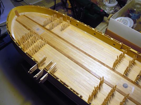
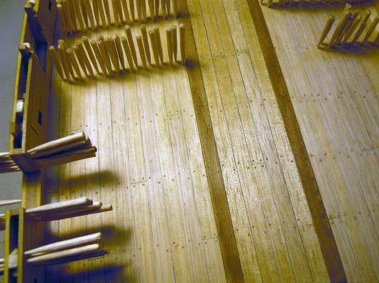
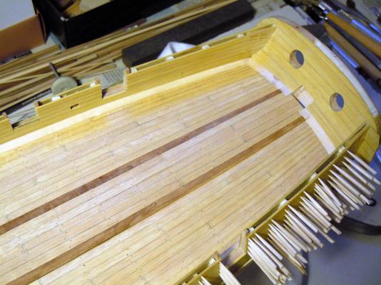
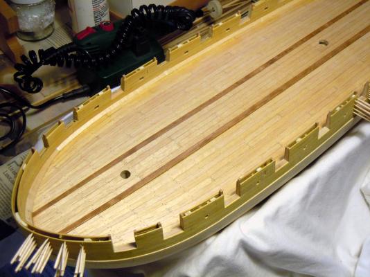
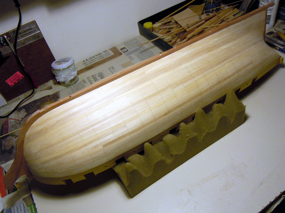
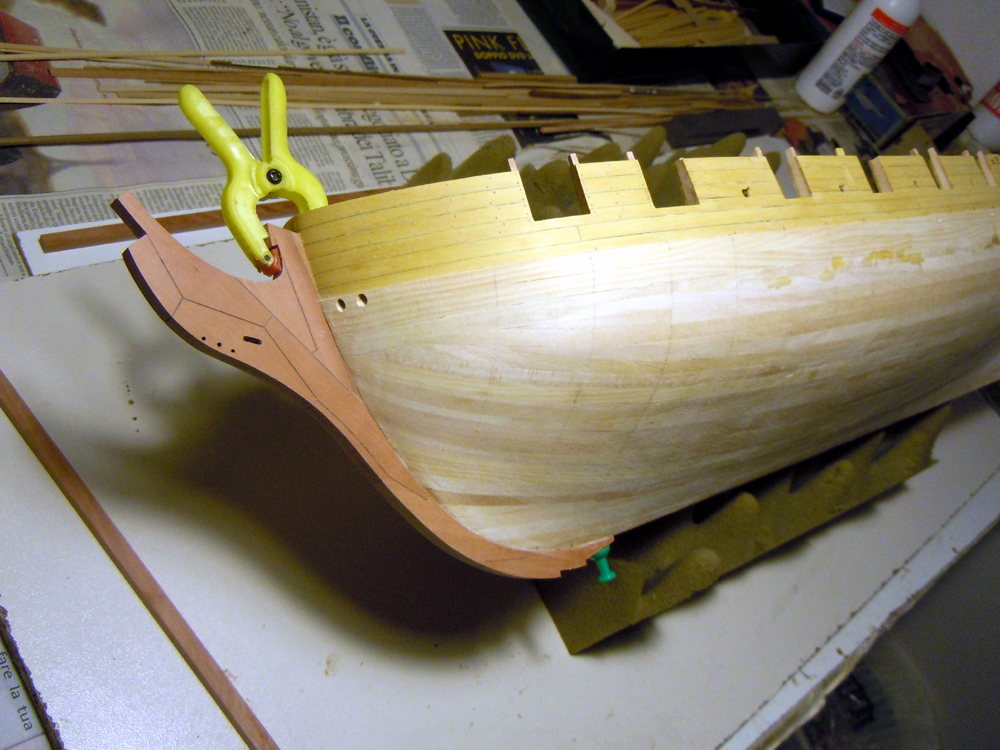
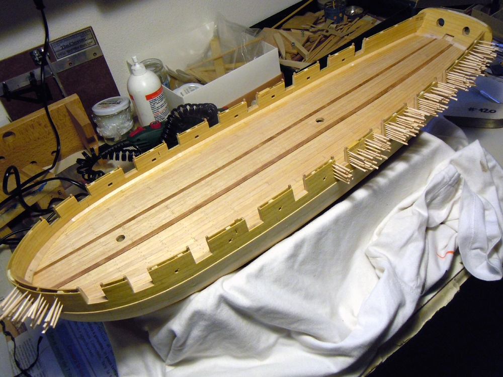
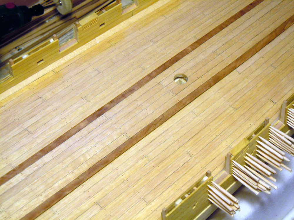
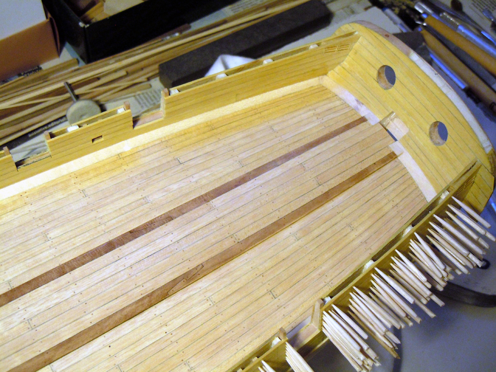
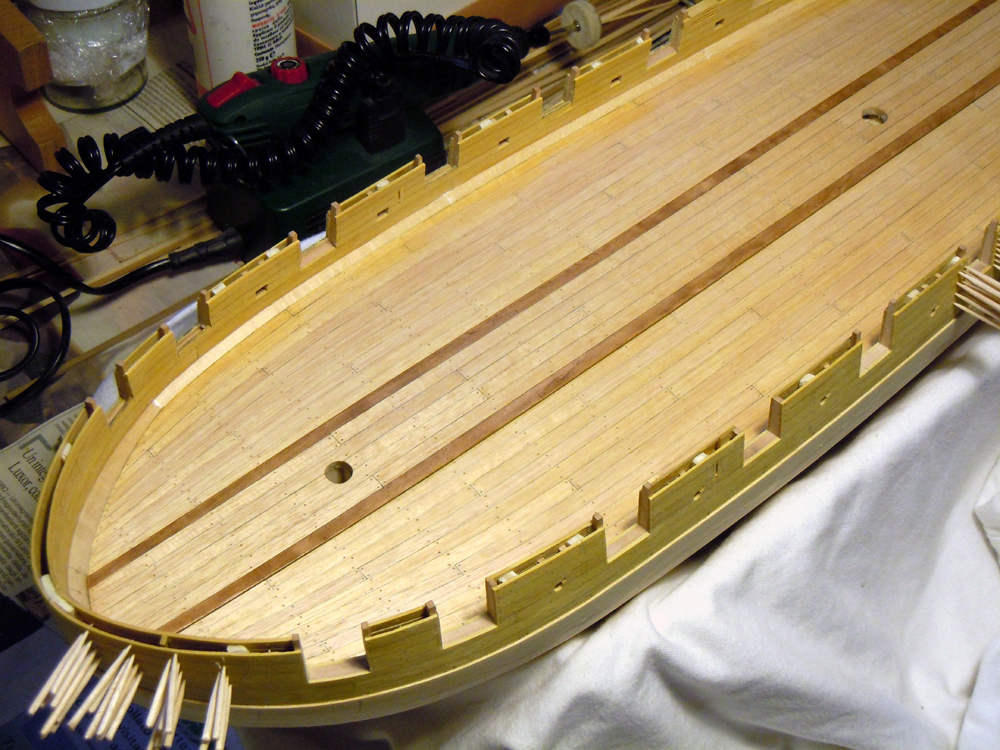
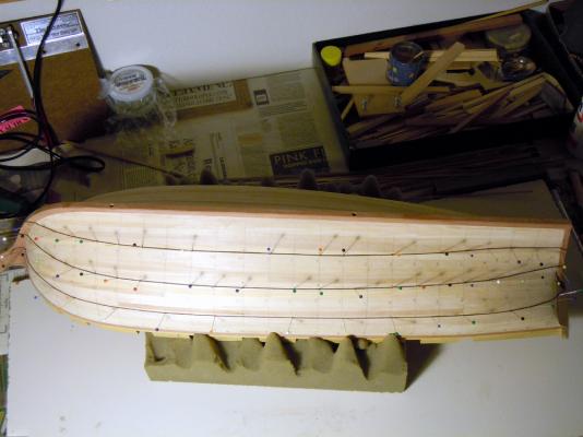
 August 3rd, 2015 Hi all just a brief update from my dockyard of the Brik de 24... its time of holidays here in Italy! I’ve been measuring and planking during all July, at a very low pace because I’m testing a new technique and my first priority is to make a good job with the spiling. Have to admit it is not easy, every planks strake has its own width that is varying from bulkhead to bulkhead. Additionally the Tanganyika veneer I’m using often splits broken just when a plank is almost finished, so have to start again...and again...and again At the beginning I was able to lay no more than 3 planks per working session, then I started planking also from the wale downward and so the speed increased a bit... nonetheless it remains a slow job. Results? I’m quite pleased by the run of the planks, even though they still need some sanding. I’m not highlighting the borders with any simulated caulking, because later I’ll cover all this areas with copper sheeting or black paint. I hope the pictures are clear enough, because I’ve used my phone instead of the usual camera: Consider that so far I didn’t have the need to use any drop plank or stealer, I’m just increasing or decreasing the nominal 5.6mm width of the planks but never more than 10-15% !! Regardless of the result, my opinion is that the method is too time-consuming (or I’m not skilled enough, yet, more probable!) if this entire job will be later covered, the effort is not worth unless the planking remain visible. So I will complete this side of the hull and then switch to my standard and quicker method for the starboard side, with the exception of 3-4 strakes of the wale that will not be coppered but just painted black. Now I’m enjoying my holidays with the family, so see you on September with new updates. Cheers Fam
-
JA I'm astonished too: I think that either that answer was another way to tell you they don't want to do the job or ... it was the wrong company for what you need. Regards Fam
-
Jack, the website seems promising, unfortunately google translator is needed to understand every single word... apparently they don't have an English version of the site, only German language... but as far as I know usually German people know English language pretty well, so it's just a matter of finding the contact address! Maybe Anobium/Christian can help with this ;-)Ciao Fam
-
Hi Jack it depends on the price... I mean, I already have a reliable method with the sticky copper tape and honestly I am more concerned about finding the carronade barrels than about the copper sheating. Just let me know, I will consider and give you an answer any way. BTW I've got three guns barrels from TheLumberyard, they are quite good quality and correct size, but I'm not sure about blackening, will see how it works or what I can do as an alternative. Cheers Fam
-
Hi JA how are you going with this terrible heat? Have you some A/C? As far as I know, Eduard is a commercial brand producing lot of after-market photoeached sheets for most kit model companies, mainly plastic. I don't think they are available for customized production in small quantities. Probably you will be more lucky with Dafi's producer, that I don't know if it is a homemade maker or industrial Have a nice evening Fam
-
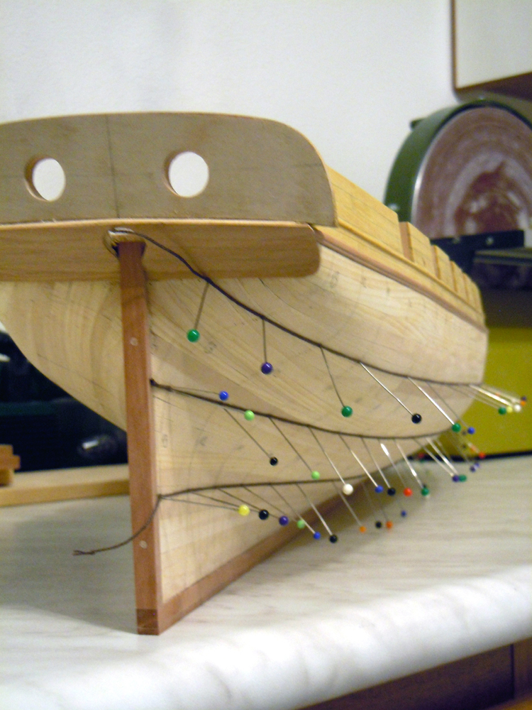
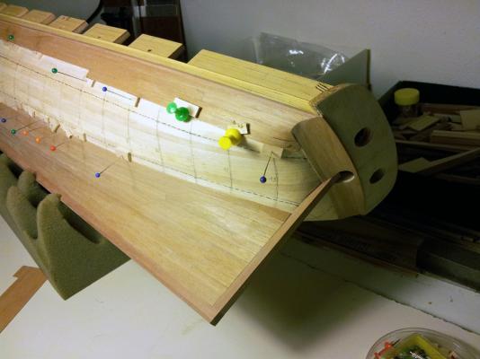
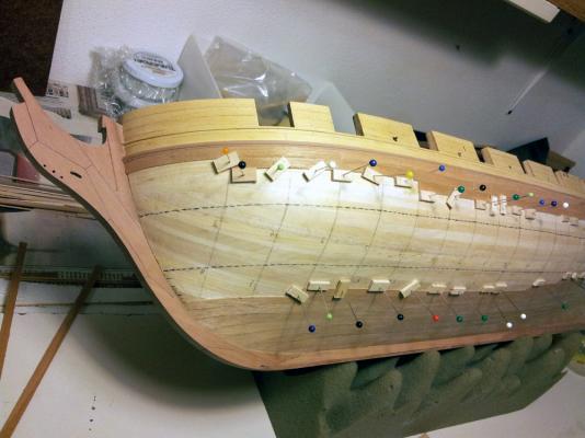
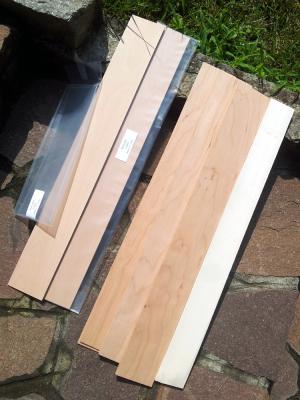
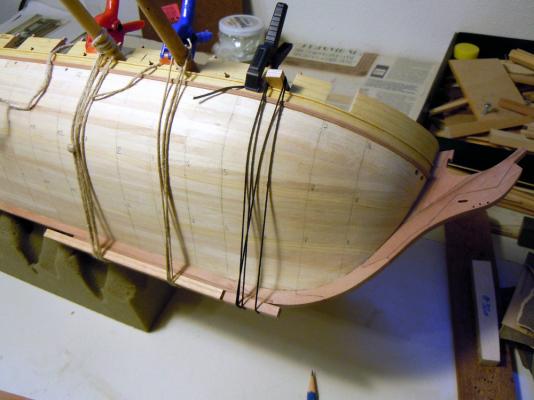
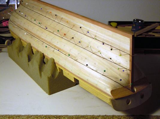
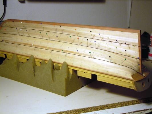
Hi all I've finally started laying the second planking, after several other adjustments to the 3 thread lines dividing the hull into 4 belts. Then I've copied-pasted to the opposite side of the hull, each thread for each bulkhead line. Finally I've traced the lines to the hull with a soft pencil and removed the threads/pins. Now the hull is divided into 4 belts that, per my intention, show the run of the planking and the tapering-enlarging of the belts. Next was to calculate the width of the planks and thus the number of planks required. I measured from the Ancre plans, for each plank strake and at every bulkhead line, and got an average width between 5.5 and 6mm. So decided to go with 5.5mm width plus a 7.2mm wide Garboard plank - measurements taken at bulkheads M1 and M2. There will be a total of 23 strakes 5.5mm wide plus the Garboard, total 24 strakes at M1-M2. Ancre plans show only one drop-plank at the bow and one stealer at the stern, both located in proximity of the keel... will see if I manage to maintain this layout or need to do some adjustment. Yesterday night started laying the Garboard, which is tapered to zero at bulkhead "IIa" and widens to 7.6mm at the stern post. In the meanwhile I'd like to show what I've received while I was in Philly: Left are Pearwood sheets from TheCrownTimberyard, right is Cherrywood and Holly from TheLumberyard. Quality of wood is very good, or even excellent, sizes are precise (in mm for C.T., in imperial units for T.L.) but surface finish is different: sheets from C.T. are as smooth as a peach skin , those from T.L. are a bit more coarse even if I chose the finest finishing. Luckily a friend of mine is so kind (thankyou Cesare!) to get them through an industrial thickness sander that greatly improves the finish and adjust the thickness to the closest mm size. Additionally, Eve from T.L. added a spare piece of Cherry (just roughly sawn to a variable thickness), I think to increase the stiffness of the package for shipping: it's good quality wood, so I got it finished to 6mm thickness: thank you very much Eve! About the prices and the shipping: prices are not cheap, but still in line with the prices of modelling material I find here in Italy. Shipping costs are definitely high: I would have not ordered anything for shipping to Italy... too expensive. Stay tuned Fam
-
Need help with rigging on the French Chebec Indiscreet.
Fam replied to DougM's topic in Masting, rigging and sails
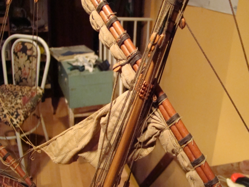
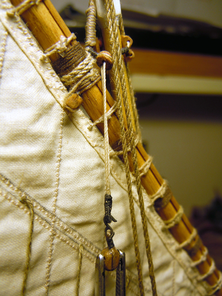
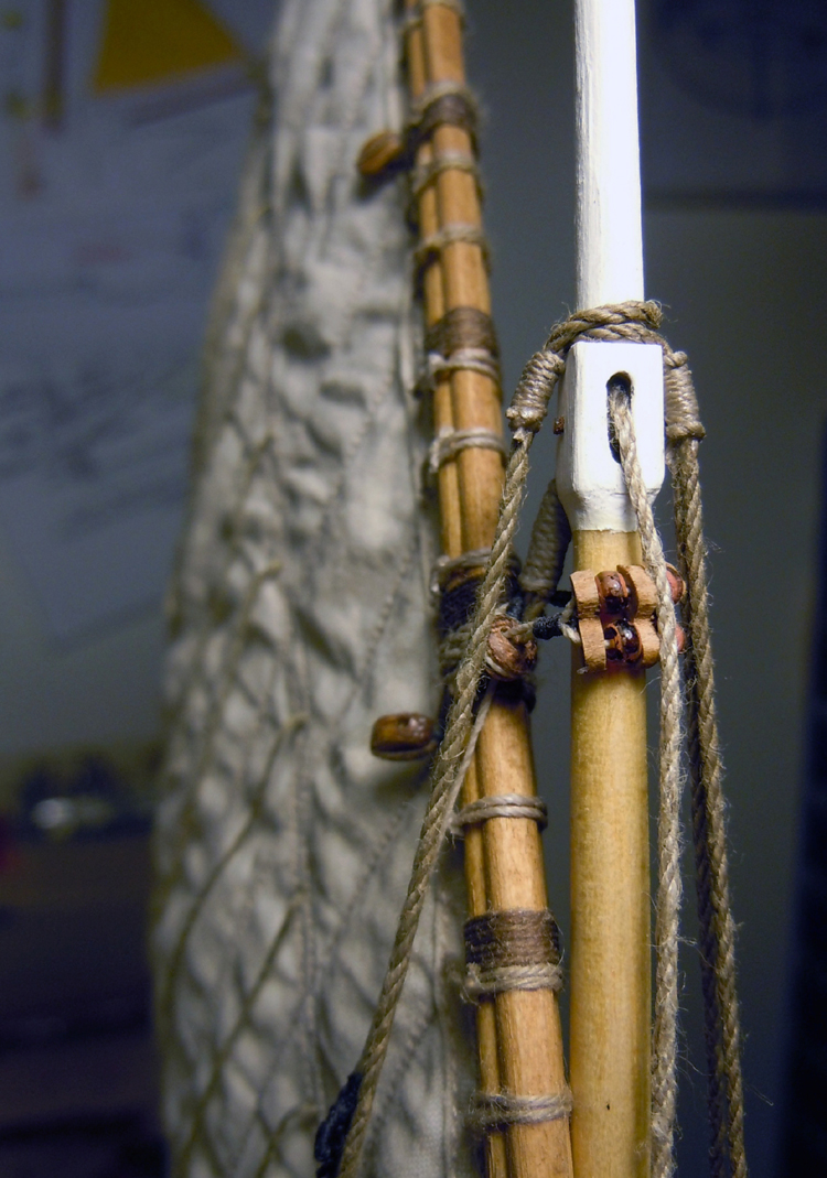
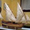
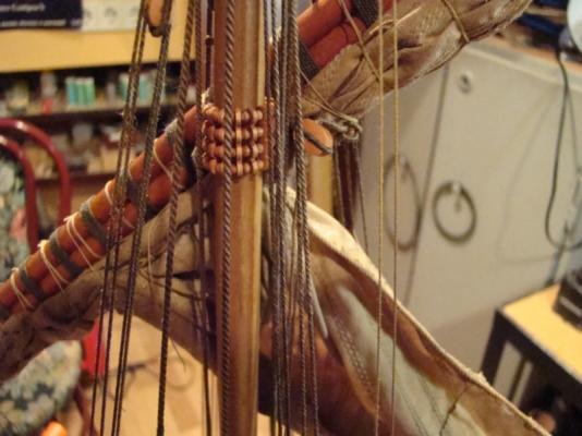
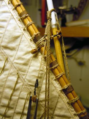
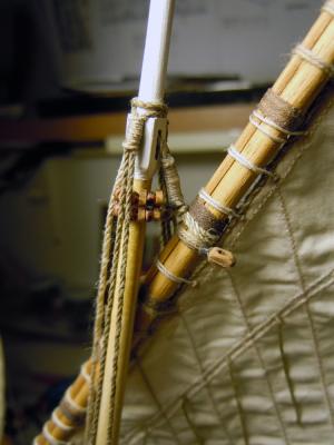
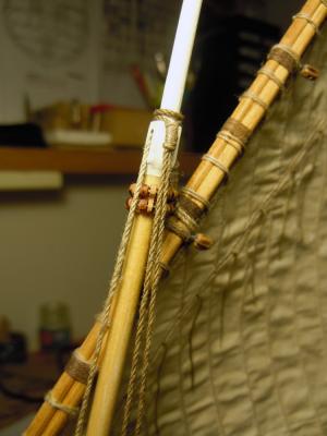
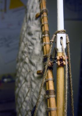
Hi hope these picture give some indication, they are examples based on: - first three is the French xebec Le Requin (models by Frolic and Roma) - last five is my Genoan Pinco (my personal interpretation based on Le Requin rigging adapted to the Pinco rigging) On my Pinco I tried to encircle the yard and the mast with the parral, but it didn't work. Much better if the parral encircles the halyard where it is tied to the yard (the one showed is the mizzen, main and fore have double halyards but he concept is the same). The xebec is slightly different as there is no single halyard tied to the yard at its middle point, but two lines made fast to the yard ends and passing through the sheaves in the mast head. Bye Fam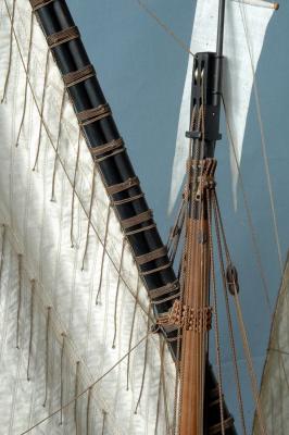


-
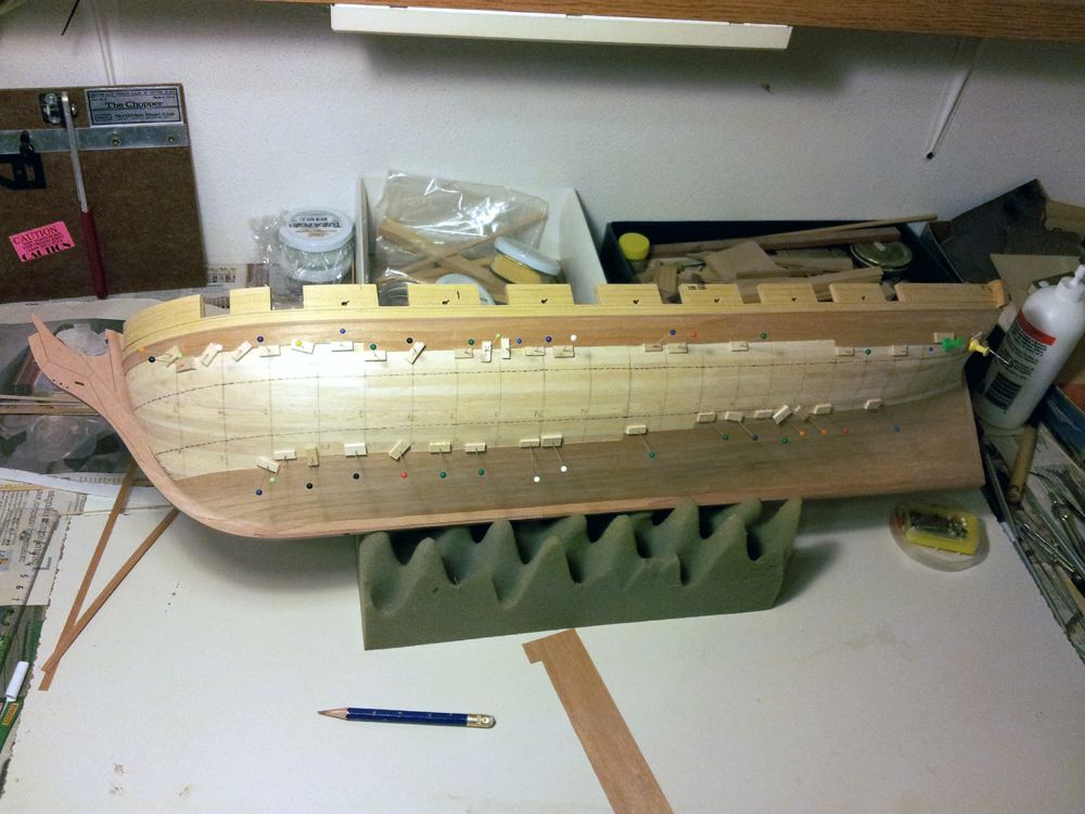
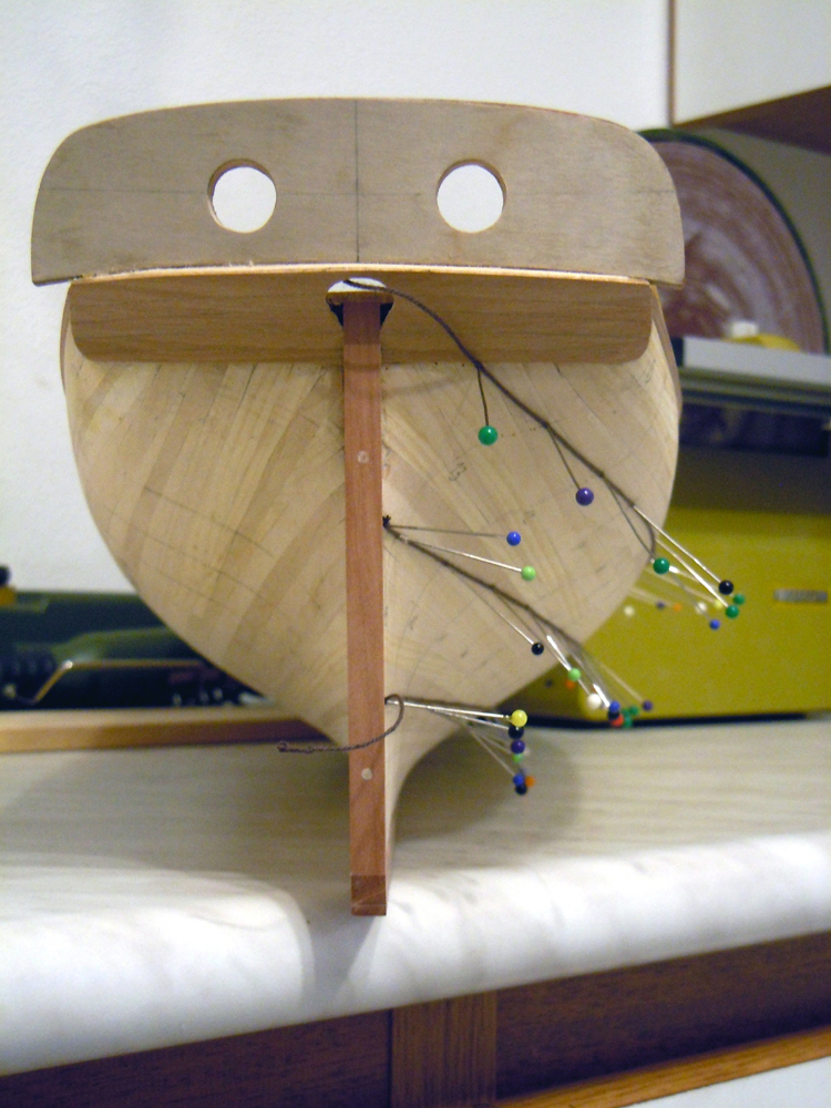
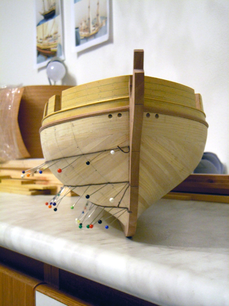
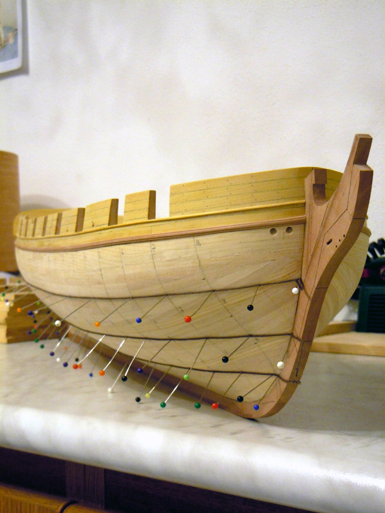
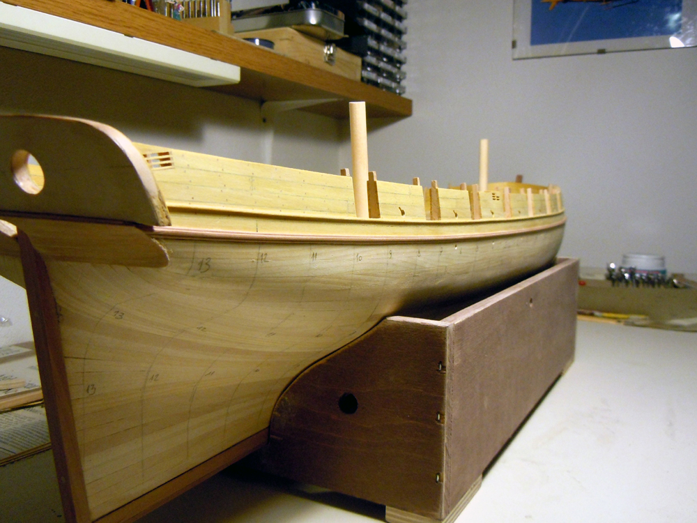
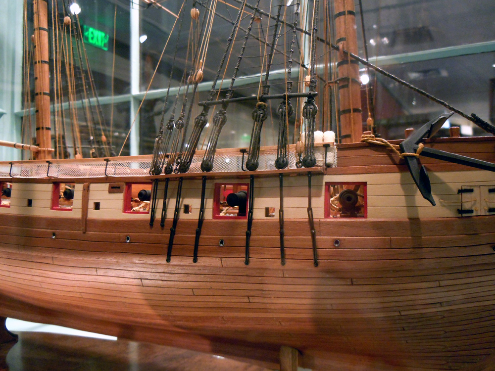
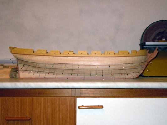
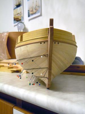
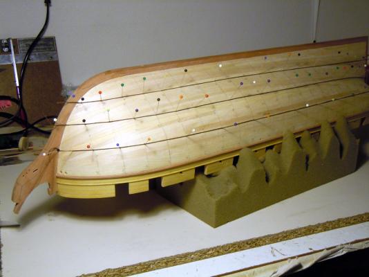
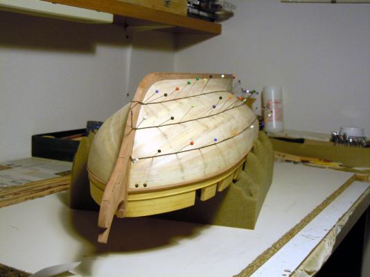
Hi all I'm finally back at the shipyard. As kindly requested to permit a better evaluation, I post 5 other pictures of the upright hull. Any indication will be appreciated and more than welcome Thank you very much Fam PS: the fourth picture show what seems an upward bend of the wale molding and gunport sills molding, but is is an optical effect


-
Congratulations Cristiano she is so beautiful and the flags really give her the touch of color that attracts the attention even more! Fam
-
OK I've got it now... I'm sorry but my knowledge of English language does not get to these levels ;-) I've plenty of them in my tools box, probably one of the most useful and flexible tool in my entire inventory!! In the meanwhile I've got a PM even from Chuck, also suggesting to take pictures of the upright hull, directly from the side, from the bow and from the stern. I will, as soon as I go back home (one entire month... how can I resist so far from my toy??! :P ). Thank you very much and bye Fam
-
Thank you Druxey, I didn't thought about this when I took my series of pictures for posting here on MSW: I checked my archive and have no pictures at all of her upright Unfortunately I'm in Philly right now, so I have to wait until the first week of July to shot them! I will, anyway, and post them here. And yes, the shape of the water scuppers will be definitely oval on the hull exterior, I imagine something like in the picture I posted previously. Cog thank you for the appreciation but the different laying of the two layers is only due to the different planking technique I'm going to use. Anyway I agree with you that the strips crossing to each other in several areas will give extra strenght to the hull I don't understand what you mean about the sewing basket... maybe is a joke but please explain Bye Fam
-
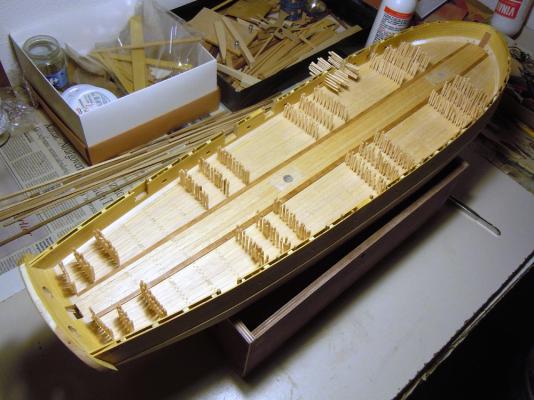
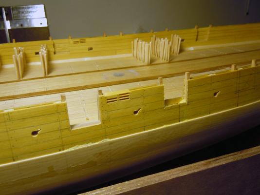
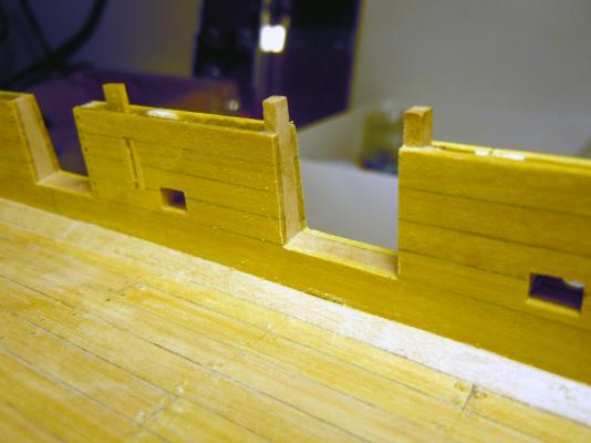
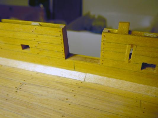
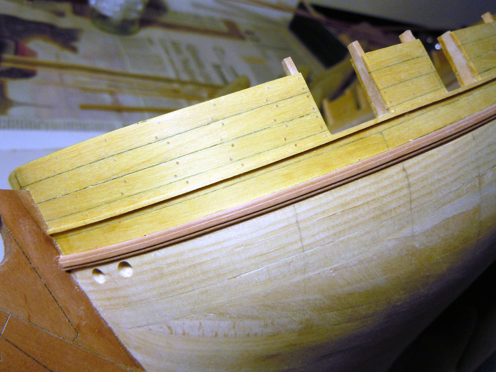
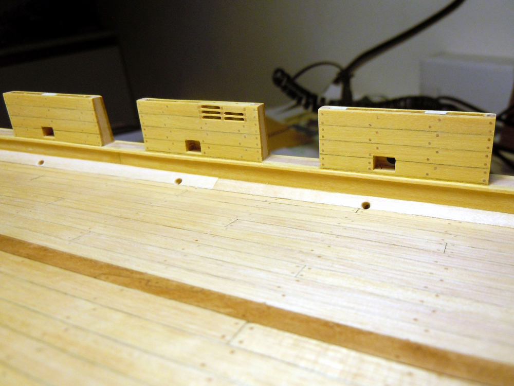
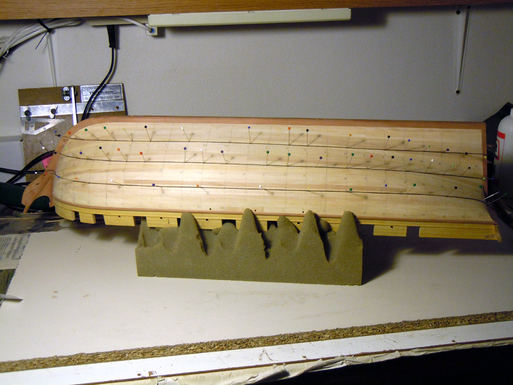
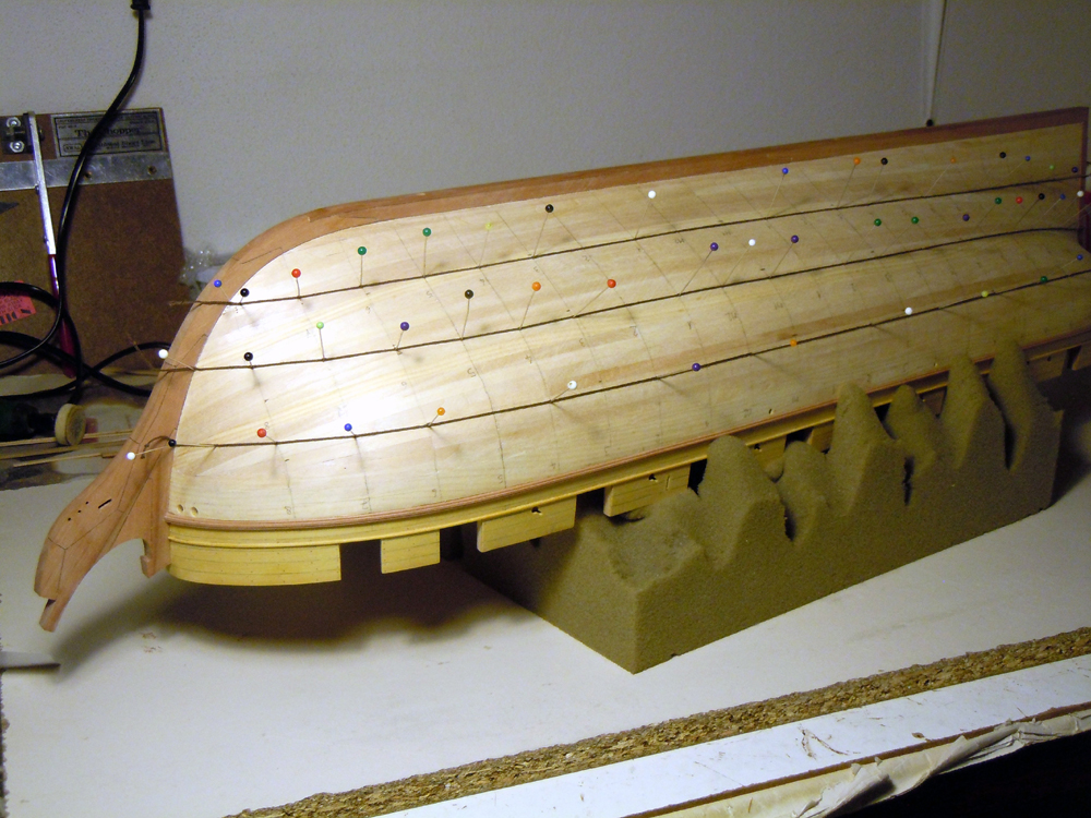
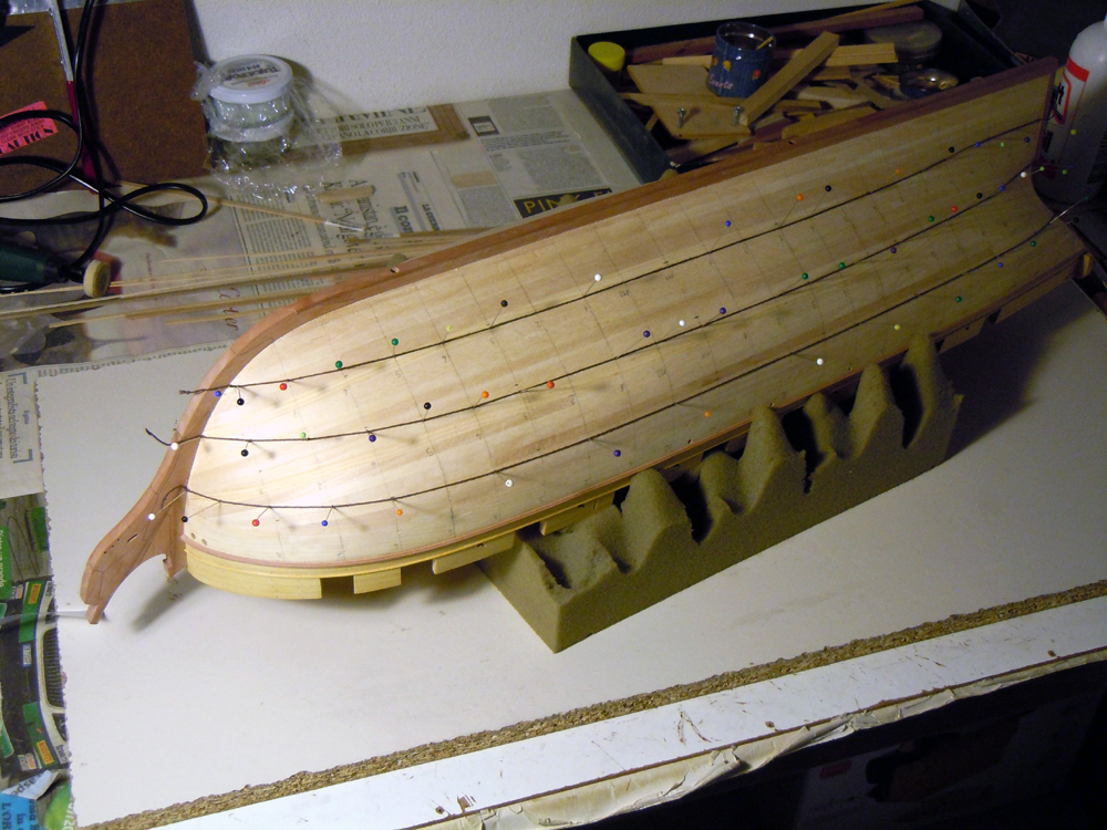
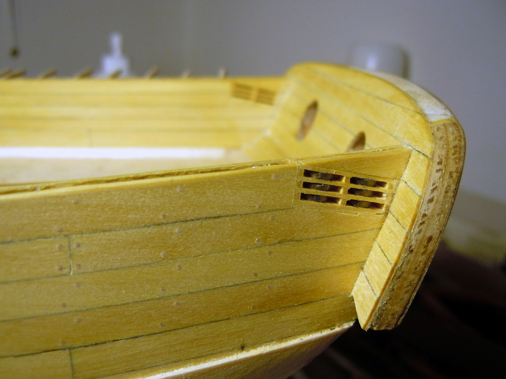
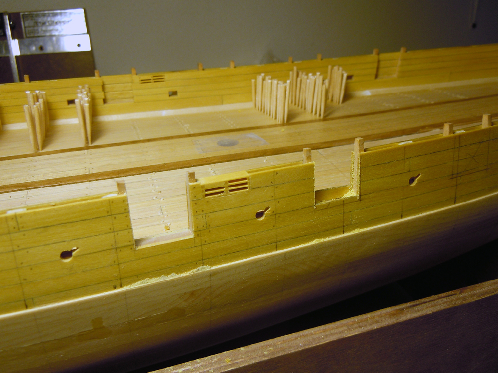
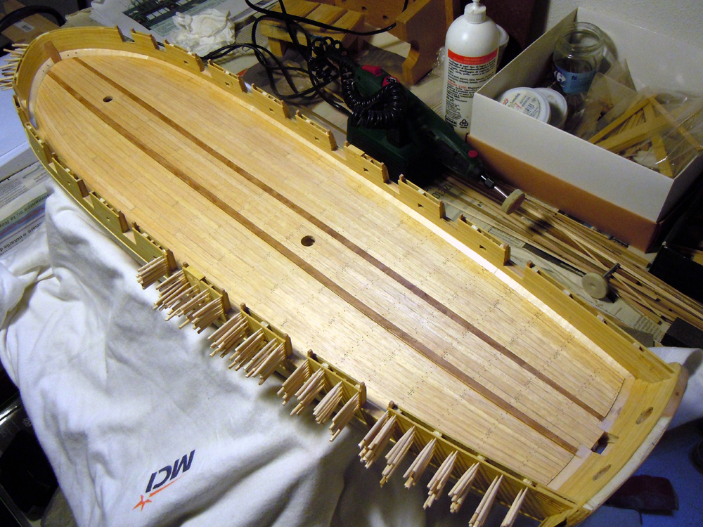
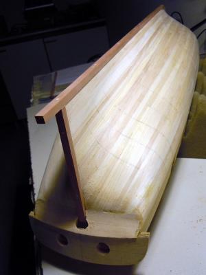
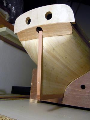
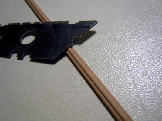
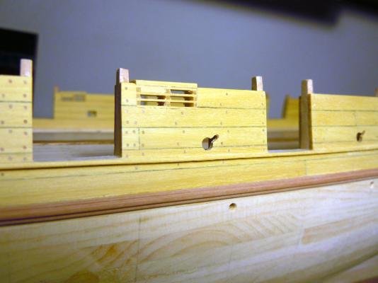
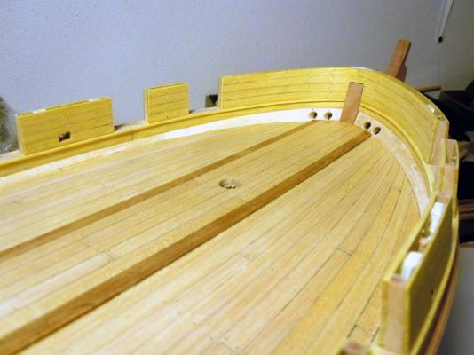
June 8th, 2015 Hi all this will be the last update from my “Brik de 24” shipyard for a while, since I’m going to close it for one month due to another business trip for the Company I work in. In these two weeks I completed several long lasting works and started preparation for the hull second planking. Keel, stern post and “shoe” Before doing this job I had to refine the hull shape at the junction with the keel parts. These are 7mm wide, so I had to measure and sand the hull in the junction area until its thickness was 6mm, to take into account for the 0.5mm thick 2nd planking layer. After this, I glued the stern post, the two keel pieces (joined with horizontal scarph joints) and finally the piece that I call “shoe”, the one protecting the keel in case of contact with the undersea floor. All junctions were strengthened by wooden pegs (the usual 2mm toothpicks). Of course the holes for the supporting screws were drilled before adding the keel parts. Here are three views: Obviously addition of the stern-post required refining of the rudder tiller hole, which I later completed by adding the 2nd planking to the counter in order to have the correct and final shape for the rudder hole: Second planking strips are obtained from Tanganika wood veneer, 0.5mm thick. Wale and bulwarks mouldings Next in the sequence, so to complete the preparation for laying the 2nd planking, was the addition of several mouldings that are needed to better define the upper boundary of the wale. Additionally, I prepared and installed also the mouldings for the gunport sills, inboard and outboard of the bulwarks. The first moulding is obtained from 3.5x2.5mm Pearwood strips that are shaped, as three-lobes, using a scraper. I was really pleased to see how simple is this method... several light passes and the moulding slowly takes shape under my eyes The important is to stick the wood strip to the work surface and hold the scraper at right angle to the wood. The gunports mouldings are obtained by cutting 1x1mm strips from Yellowheart wood: not an easy task, because this wood is extremely hard but also fragile and tends to split apart under the table saw blade, when cut in very small strips. The next pictures show the results: I really like this other picture because shows the beautiful curvature of the hull, as it is highlighted by these mouldings: The lines defining the bulkheads positions are also traced on the 1st planking and will be used to calculate the shapes of the second planking strips using the method described in C.Passaro tutorial. Bulwarks treenailing Very few to say about this boring work. I didn’t want to leave it behind, as it is another milestone to be passed for the preparation of the deck. The interested area was the interior of the bulwarks and the interior of the transom. Technique has been thoroughly described before, so the only detail worth noting is the total amount of nails I installed... 2860, plus or minus ten! It’s not the biggest number I’ve seen here on MSW, but gives an idea of what anyone has to be prepared to when the decision is taken! After having completed the job I have to admit I’m very pleased by the result, the treenails add a beautiful texture to the look of both deck and bulwarks... just wondering how much of it will remain visible after installation of all deck fittings and guns... Here are a couple of pictures: As I had the hull in the upright position, I also finished the top of the bulwarks by removing the tips of the gunport framings and sanding the bulwarks top flat: now they are ready to receive the gunwale. Also visible in above pictures are the hawse holes and the water scupper holes. Hull lining for planking Just before temporarily closing my shipyard, this was the last task I did. It needed an entire work-session of measurements and comparison with Ancre plans of planking, but I think I’m pretty close to an acceptable result. I ask all of the readers to write their opinions, and also ask Chuck to drop by here and give his judgment, so that when I’ll go back home in a month I can copy-paste to the opposite side and start planking. I will really appreciate any suggestion and apologize for posting maybe too many similar pictures! Bye Fam


-
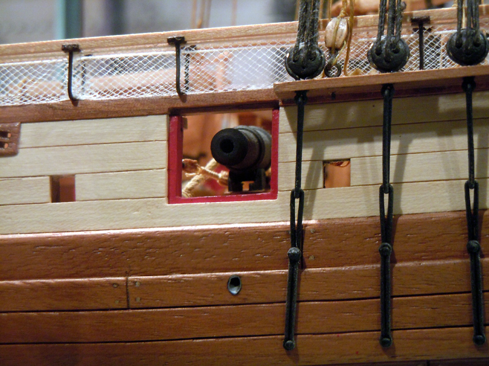
In the meanwhile your beauty is still missing a couple of sheave blocks, vertically oriented in between gunports 4 and 5 (or 5 and 6, see my Brik)...;-) Ciao Fam
-
Mmmmh... you are making me curious!! Ciao Fam
-
You have done lot of interesting researches, have to admit that symbology laying beind any part of these flags is very complex! Chapeau for the interesting lesson of italian history, it's always interesting to learn something new Ciao Fam
-
Hi Cristiano is your Polacre a merchant or a military vessel? Because I remember from my last visit to Venice that on military ship flags the S.Marco lion helds a sword in its fore right paw. Maybe this is not your case, just a warning Ciao Fam
-
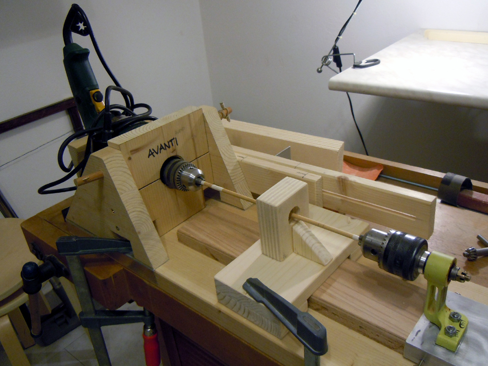
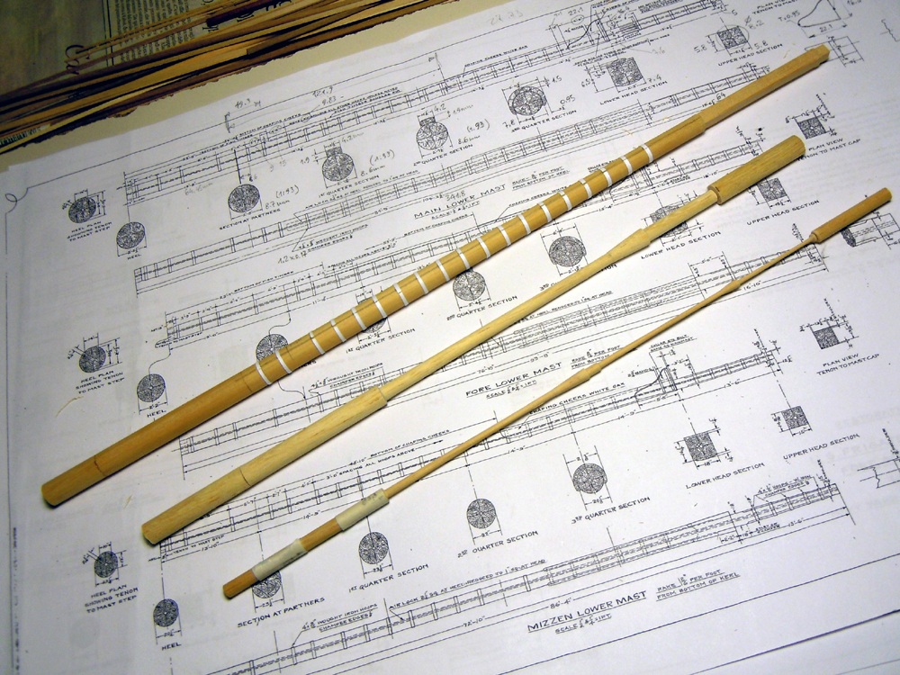
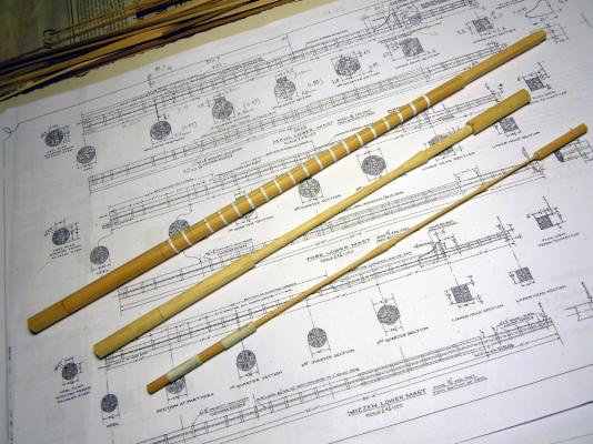
Thank you Mark unfortunately I've no skill at all, nor the tools, to turn anything, apart from some very limited capability with a power drill that I transformed into a homemade lathe. I use it for shaping the masts and yards: No possibility with any metal, it's too imprecise! And this is a big problem for me, because I don't know how/where to get the guns and carronades barrels: the optimum would be to turn them in brass, this is the obvious solution. In fact, I've contacted Johann (archjofo) who is building Le Créole french corvette of 1827: I cross-checked his carronades with Ancre plans and apparently the design is the same. Unfortunately he got his barrels from a friend, so this is not a viable solution... sobh Now I've a half-committment with a friend of mine, but he's going to have a babyboy and so I see very few possibilities... double sobh :( Cheers Fam

-
Thank you Carl, I appreciate!
-
Confirm, for me as well! Fam
-
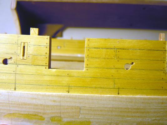
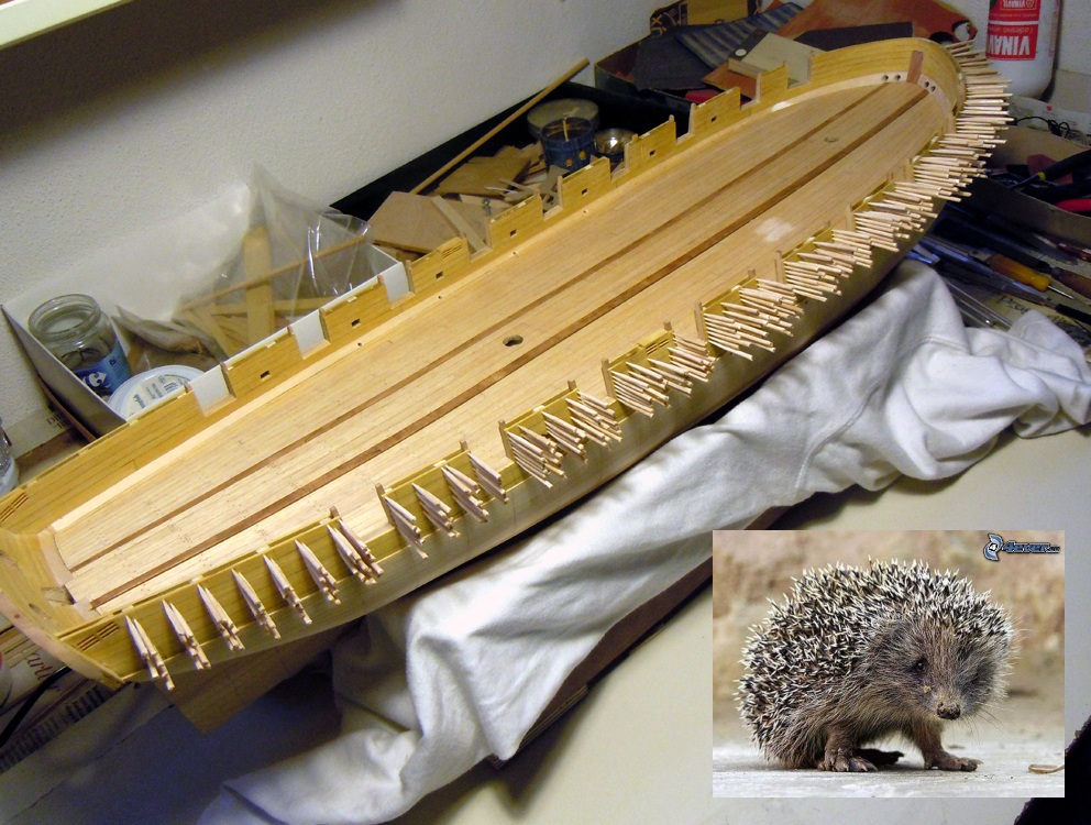
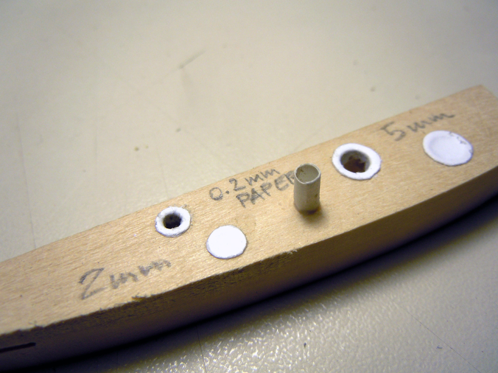
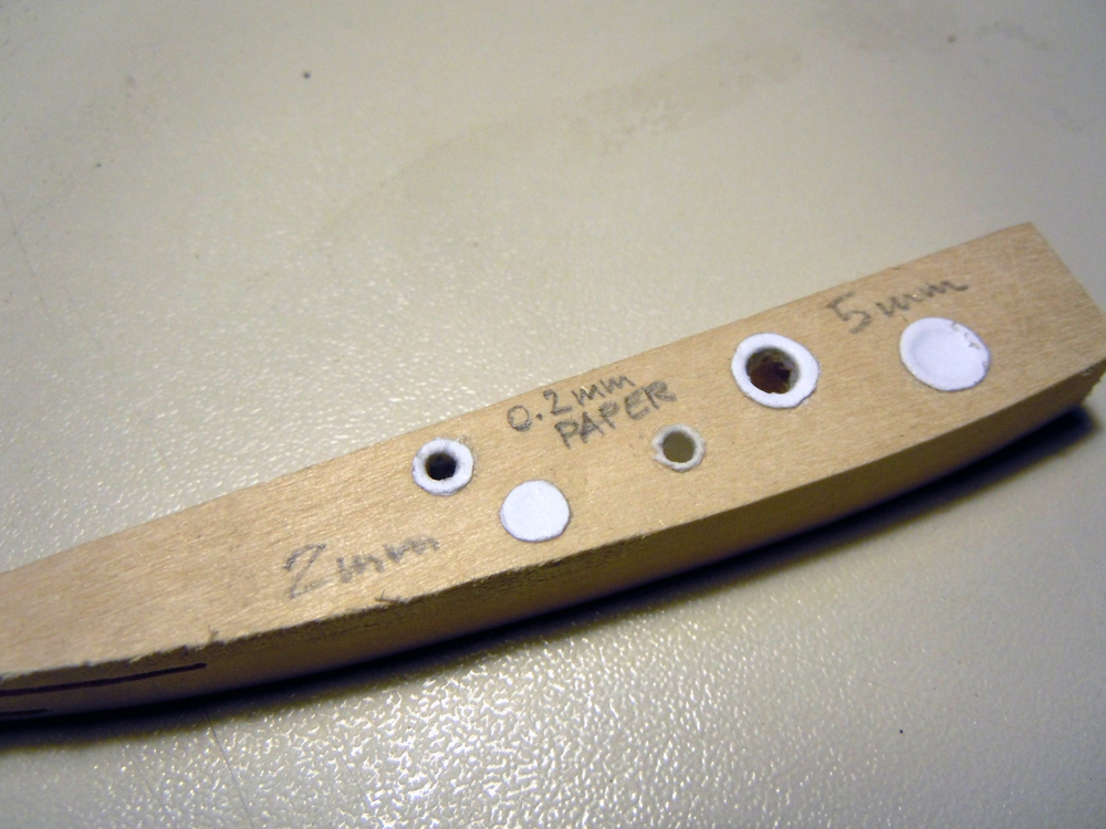
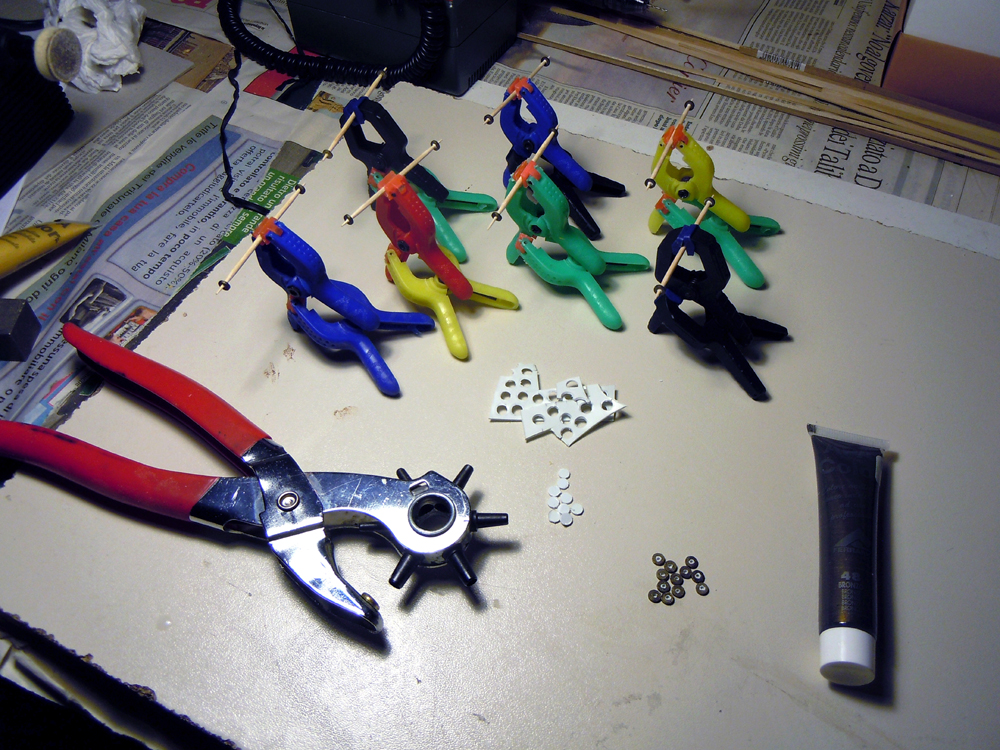
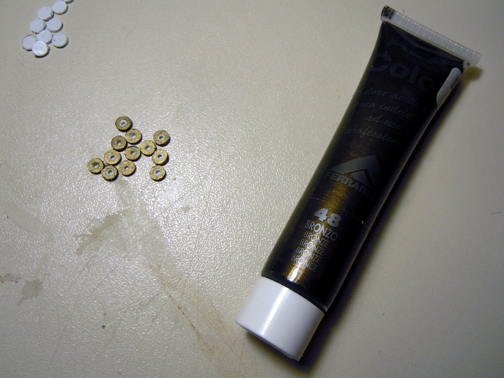
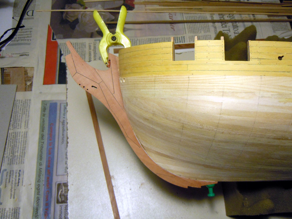
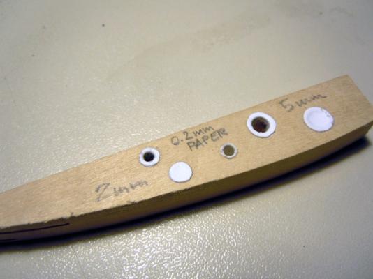
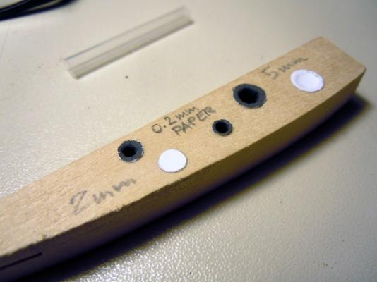
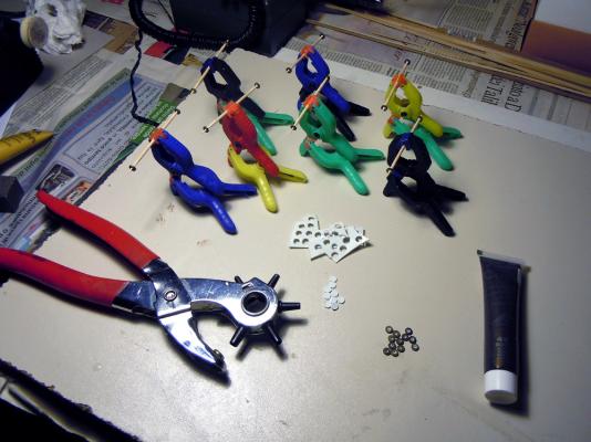
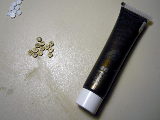
May 20th, 2015 Hi all here I am to satisfy someone’s curiosity... Firstly, my own personal porcupine! LOL The lighter spot on the deck, in front of stbd gunport #3, is where I had to sand off the sealer to correct a defect, still to be fixed with another coat of sealer. And now the tests for the water scuppers lining. I drilled 3 holes 2mm diameter (left, for the scuppers) and 2 holes 5mm diameter (right, for the hawse holes) in a scrap wood piece. Then cut 2 disks from a piece of thick paper, about 4mm diameter, and 2 other disks of 7mm diameter. The problem with this method is to give the paper a sufficient lip surface to let the glue hold down the paper on the border of the holes when the paper is pressed into the hole... I tried with 1mm wide lip, but maybe 0.5mm is feasible if a thinner paper is used. The last 2mm hole is used for the second method, using a paper roll (standard printer paper) to be inserted in the hole. The roll is then cut with scissors as close as possible to the wood surface, then the paper is soaked with glue and pressed to the hole border using a conic tool that creates the lip. This is similar to the technique plumbers use to prepare the ends of metal pipes for leak-proof connections. And this is the final effect after a coat of dark gray acrylic paint... I didn’t even try to be precise with the brush tip, and the lining lips are far from perfect, but considering the size I think the result it’s not bad! Maybe a slightly lighter shade of gray... Just one consideration about the technique: gluing a paper disk above the hole borders, then pressing the tip of a tool trough the disk center to create the hole, is easier where accessibility for scissors is poor. Conversely, the pipe method seems to give a better result (well, to me), but free space for the scissors is needed. So I think I’m going to use the first method on the inside, which will be also partially hidden by guns and various deck fittings, and the second method outside, where the lining will be perfectly visible. Finally, all these holes were at 90deg to the wood surface, things may be slightly different when the hole is angled... Next test: the sheave block pulleys. The scope was to simulate the pulleys with something that gives the ‘idea’ of a pulley, even if the grove is not visible. Also consider that most pulleys will have a rope passing through, so will be only partially visible. The method I used is the one I’ve already described, and you can see in the picture below the tool I used to punch the styrene disk out from the 1mm sheet. The sequence is straight-forward, no need for further explanation I think. I painted the disks with bronze acrylic paint, but the result is maybe a bit too dark... The look is not a shining brass as I’ve seen in many models, but I prefer not seeing any shine in my model, I think it’s too evident and not realistic... well maybe with the exclusion of the ship’s bell! Don’t know, what do you think?? Any comment is really appreciated. And finally yesterday evening I added the stem pieces/cut-water to the bow: the piece is made of three main parts, the other joints lines are just simulated... well, it will be partially painted and partially copper sheeted, so simulating the joint is a non-sense, but I wanted to see how it looks! I had to cut a slot in the bulwark external layer of Yellowheart planks, because this layer is glued externally to the extension of the false keel, while the internal profile of the stem timber exactly follows the false keel profile. Ideally, the hook of the stem timbers (the upper appendix for the main stay that is hold by the clamp in the above picture) has an extension internally to the bulwark that I added as a separate piece before planking the bulwarks: you can see it in the first picture of today, same color of the stem pieces. If you compare this detail to the same in JackAubrey’s build-log, he cut all the way through the bulwark and the extension is integral with the stem timbers... definitely a better approach, but I was too late ! I also had to cut a slot in the forward side of hull basswood planking, to 2/3 of the height down from the wale (about where a darker strake is laying), to let the cut-water reach the false keel profile. Apart from this, the matching is quite good and there is a little slot left free for the second planking layer. I’m now preparing the keel pieces; they will be two, and will be joined to the cut-water and to each other by scarph joints (where the green headed pin is visible). Cut-water and keel pieces will be fixed more strongly to the false keel by means of 2mm wooden pins. On top of the keel, the ‘shoe’ will be added covering the fixing pins. The second step in front of the green pin is just the housing for this piece. Two holes will have to be drilled in the keel and shoe pieces for the bolts of the model supports. And this is the end for today Cheers Fam


-
Thank you Ulises Victoria, my credits to you as well, because I got the idea from you and used in my Pinco back in 2009-2010! And confirm it works very well! Bye Fam
- 593 replies
-
- 2
-

-
- royal william
- euromodels
- (and 1 more)
-
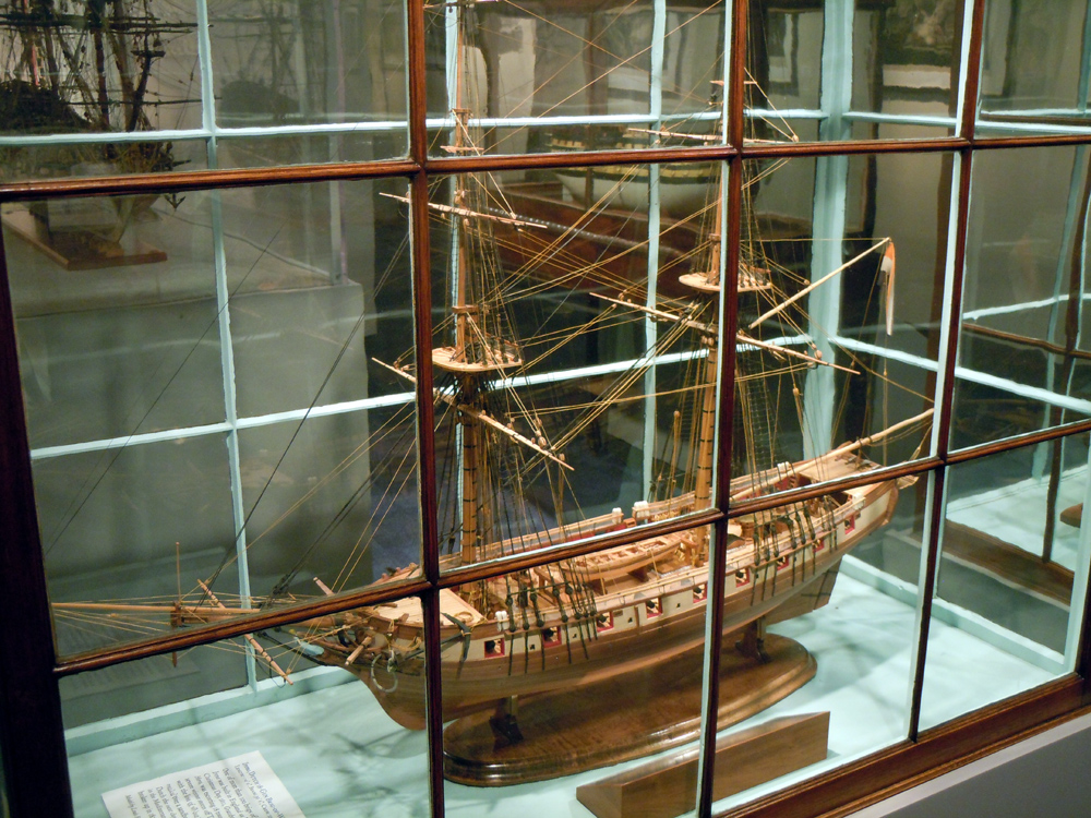
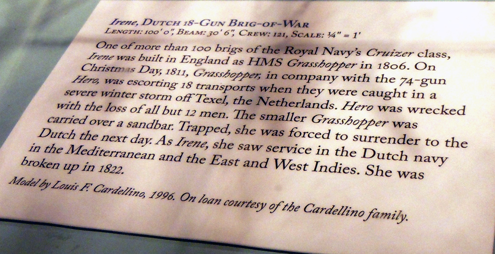
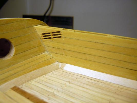
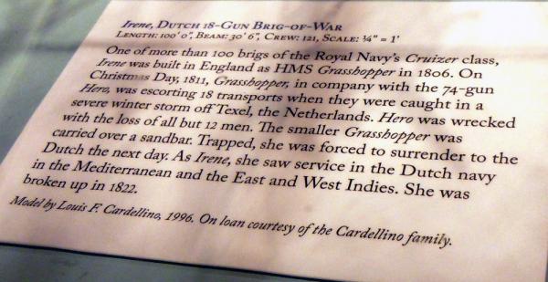
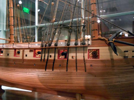
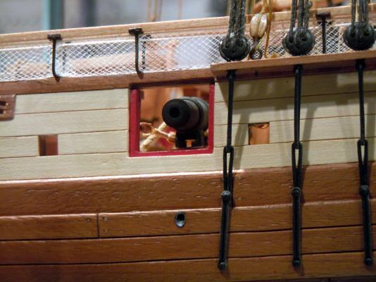
Hi all yesterday I tried a variation to Tlevine method for scuppers lead lining, that I’m hoping to use on the bulwark outside (Tlevine’s method on the inside end). I got inspiration from the model of the Dutch brig Irene (formerly HMS Grasshopper), a British built brig of 1806, which I’ve seen in Annapolis US Navy Academy museum... On the outside of the hull the scuppers look like a pipe cut at an angle, flush with the hull surface... Unfortunately the inboard ends of the scuppers are totally missing (!), an evident error of the model. So my idea was to roll a strip of thin paper around a drill bit, let’s say 1.5-1.75mm diameter bit for a 2mm scupper hole. The paper is glued to itself, creating a small pipe. The pipe is then slipped and glued into the scupper from outside, and cut flush when glue is set. Finally painted medium gray. I did another test on the same scrap piece of wood where i'm doing the other tests: this evening will cut it and see how it looks like. Tomorrow hope I have something new to show you. Cheers Fam

-
Thank you Carl had a look at DanVadas's method and will give it a chance if the other is not working, because use of styrene tubes is a bit harder. Yesterday did a test with heavy paper (0.15-0.2mm thickness) and Tlevine's method: the result is not bad at all, have to say! In the meanwhile the porcupine look is increasing: treenailing of the starboard bulwark is completed on the outside, only need to sand. And also prepared a set of pulleys for the bulwark multiple sheave blocks. As I don't have any tool, or even skill, for lathing brass pulleys I decided to simulate them using styrene sheets from Evergreen, 1mm thickness. Will show you the result asap, so you can give me a go-nogo! I'm also looking forward for the next job, which will be addition of the stem timbers (cutwater), keel and stern post. In anticipation to this, yesterday evening started sanding again the basswood planking strips in order to have a 6mm total thickness of the false keel at the stern, suitable to match the 7mm thick keel and stern post. Then will have to cut a suitable slot in the 1st planking strakes at the bow, to house the stem timber and cutwater I've already built. Ciao and.... stay tuned Fam
-
May 15th, 2015 Hi all lot of work but so little to show...! I’ve completed the weather deck treenailing, sanded and sealed with matt sanding sealer. Then I’ve cut the gunports and started treenailing the bulwarks. Finally I’ve drilled the water scuppers, but unfortunately don’t have images of this last job. So, some pictures of the various phases: Treenailing... well, deck and bulwark and gunports were not done in subsequent steps because treenailing is so boring that I couldn’t resist the temptation of jumping to other tasks here and there... This is a small area of the deck that I’ve already sanded to see the final effect... The holes are marked by pencil, then punched with a needle point and drilled at 0.6mm. Then the tip of the nail is inserted with some white glue, let dry, cut as close as possible to the deck surface and sanded flush (which also helps cleaning from any residual glue). And this is an overall shot of the entire deck, just to give an idea. I left some alternate free areas for better accessibility, then cut the wooden pegs flush with the deck and treenailed the remaining areas. I couldn’t resist the temptation to cut the gunports because wanted to see the result of my building method for their framing... Here you see the Pearwood framing exposed, and contrasting with the Yellowheart wood of the bulwarks planking. Also evident is the upward tapering of the bulwark, as per Ancre plans. And the following pictures show the treenailing test for the bulwarks (inboard-outboard). Treenails are Birchwood toothpicks, the same material as for the deck. Treenailing extends only to the area that will not be painted, so only to the first 4 strakes down from the bulwark top. A shot of the completed deck, after sanding. Treenailing of the port bulwark is completed on the outside only: it requires about 500 nails for each side, because the vertical rows of nails are more closely spaced w.r.t. those of the deck... so still other 1500 nails to go! Finally these pictures are taken after application of one coat of matt sanding sealer to the entire deck: difference is subtle but evident, the color of Ramin planks is warmer and the treenails are more contrasted. The yellowish deck area close to the starboard bulwark is just a reflection from the bulwark planks, not a color defect. Finally, I drilled the water scuppers: they are 4 per side just in front of gunports 5-6-7-8, 2mm diameter, drilled in the waterways at the same level of the deck. I used the method of progressively drilling from outside and from inside, until the two drill bits met in the middle. This way I had no problems with the linearity of the holes. I finished the inside of the scuppers, in the waterways side, with spherical diamond grinders. Could not do the same to the outside because the outward holes are in the area still to be covered by the 2nd planking. These holes were lined with leather or lead: I’ll use the method suggested by Tlevine, in his buildlog of the HMS Atalanta... will see how it works. My best regards and stay tuned! Fam