HOLIDAY DONATION DRIVE - SUPPORT MSW - DO YOUR PART TO KEEP THIS GREAT FORUM GOING! (Only 36 donations so far out of 49,000 members - C'mon guys!)
×


Fam
-
Posts
185 -
Joined
-
Last visited
Content Type
Profiles
Forums
Gallery
Events
Everything posted by Fam
-
 My personal experience, if this can help, starts here and continues in the following posts: http://modelshipworld.com/index.php/topic/8675-le-colibri-by-fam-french-brick-de-24-scale-148-1808-pob/page-5#entry365548 Cheers Fam
 -
Hi Michael are the parts laser cut? I'll follow your built with lot of interest Fam
-
Johann I only wish to say you that your pictures are so fantastic that I've just downloaded the entire sequence you have posted, both for the Pinnace and the Cutters, as a tutorial: when the time will come for me, I will try your method and hope I manage obtaining a final result at least close to what you got!!! My admiration and respect!! Fam
-
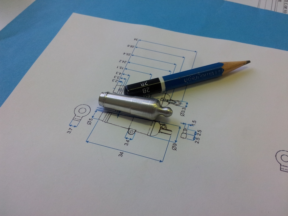
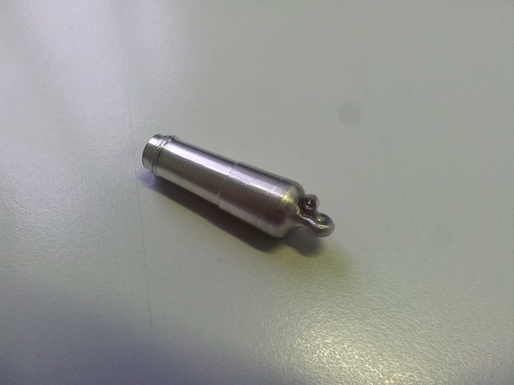
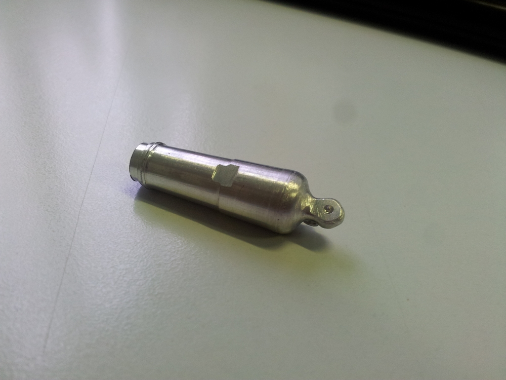
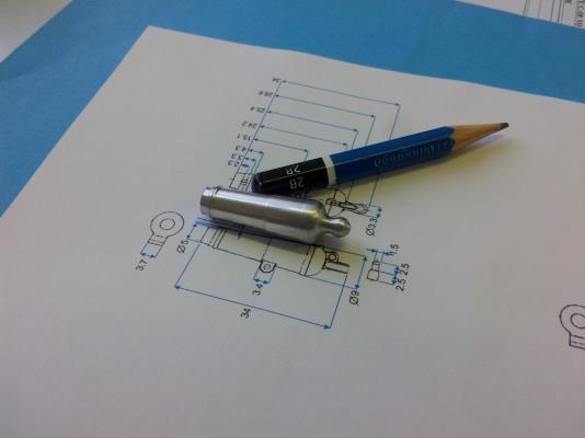
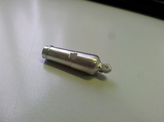
February 17th, 2016 Just a quick update on the works in progress... Decoration of the stern galleries and transom is ongoing, taking lot of time ... in the meanwhile I'm preparing something different, with the precious help of a friend of mine who owns a lathe and, more important, the skill to use it : This is a master in alluminium, to be used for casting the 14 carronades barrels in pewter. Cheers Fam

-
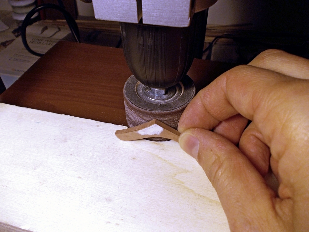
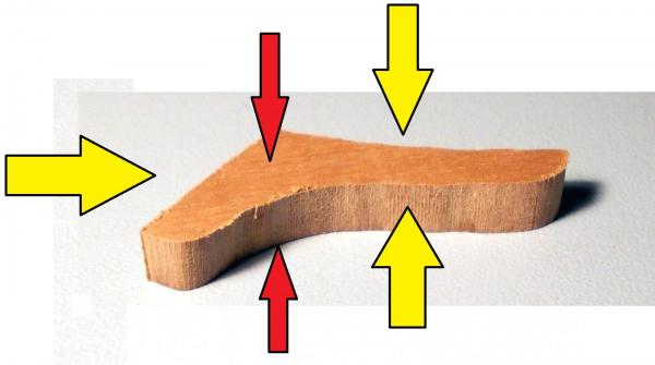
Sean given the type of frames you have, I suggest you this high-tech tool that I built for my model: just cut away the area shown by red lines, using a grinding disk in your Dremel. Position the plank in the gap you cut out and clamp to the bulkhead. There are various sizes of clamps, just chose the most suitable for your frames. Some are really strong and keep hard spring-back push, but of course it is better you pre-bend the planks before gluing. Cheers Fam
-
Very nice gratings Johann! I still have to test this method. Just to be sure for my correct understanding: you start firstly cutting in cross-grain direction with the deeper cuts, then cut along-grain with the shallow cuts, then fill the along-grain cuts with battens as wide as the shallow cut depth, then sand the opposite side until the grating emerges? Is this the correct sequence? And the saw blade thickness must be the same as the battens thickness and the cuts spacing (=steps)? and how thick is the blank you start from, and how deep are the cuts (deep ones and shallow ones)? Thank you so much for your patience Fam
-
Thank you alla for the nice comments and likes! Druxey, I suspected the joint between the two beams would have been a weak point... So, considering to rebuild the piece and considering that I don't have any wood with the angled grain that would be needed (like for knees), how do you suggest to keep the wood grain? In line with the horizontal beam, or with the vertical, or something in between? Thank you in advance for any tip Cheers Fam
-
Thanks Dirk when I look at my brig from, say, 5m distance I almost don't see the results of 2 weeks work so it must be necessarily very small Fam
-
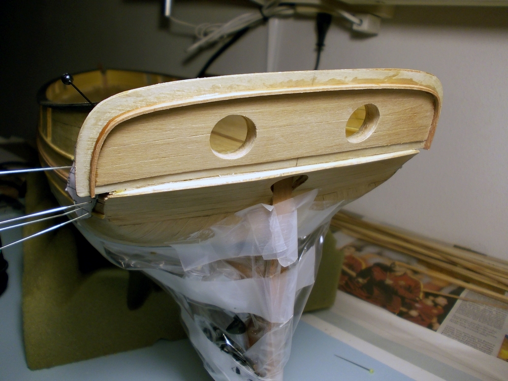
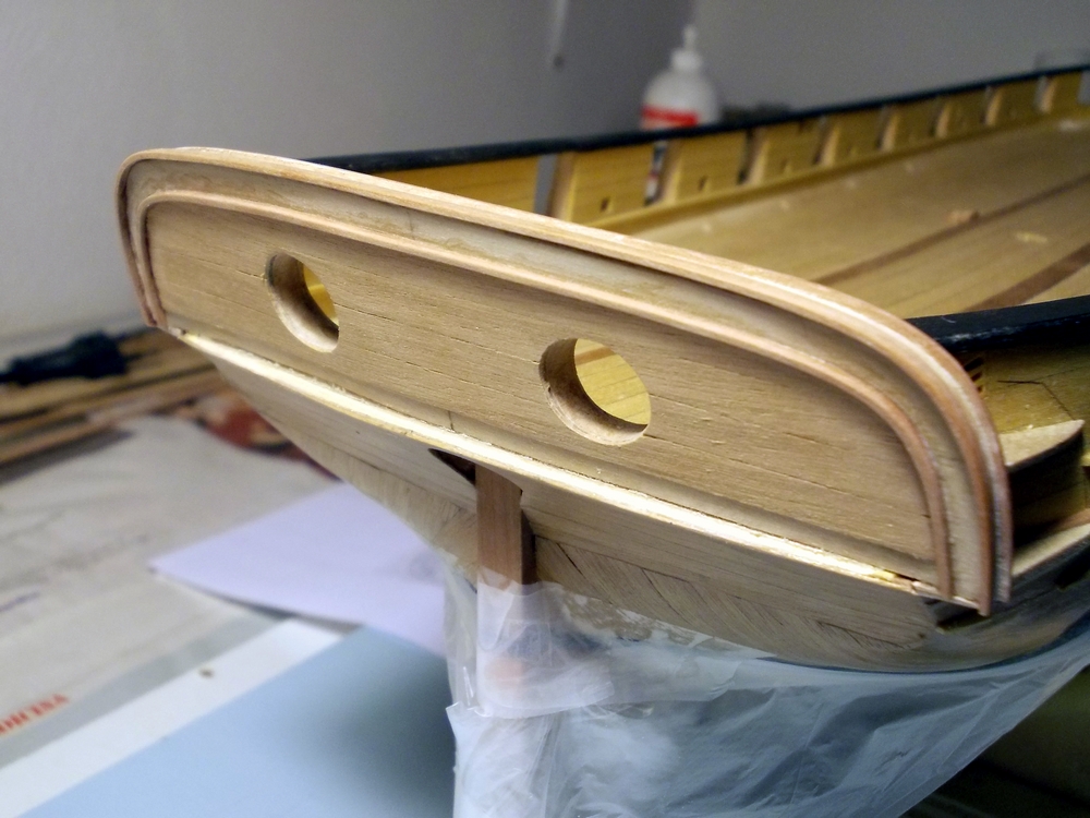
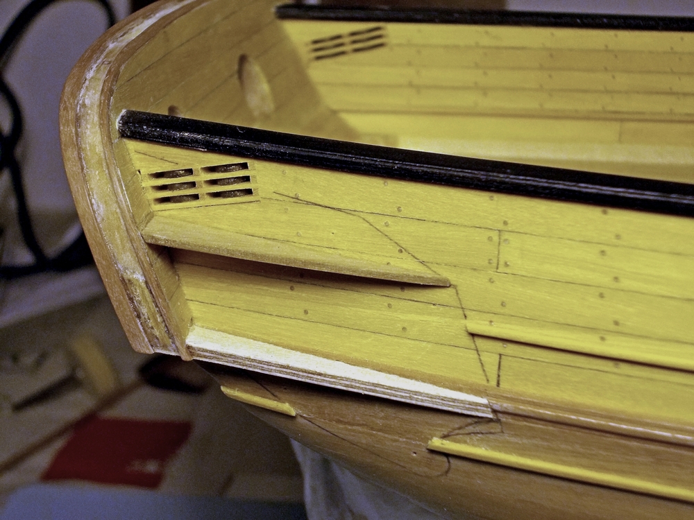
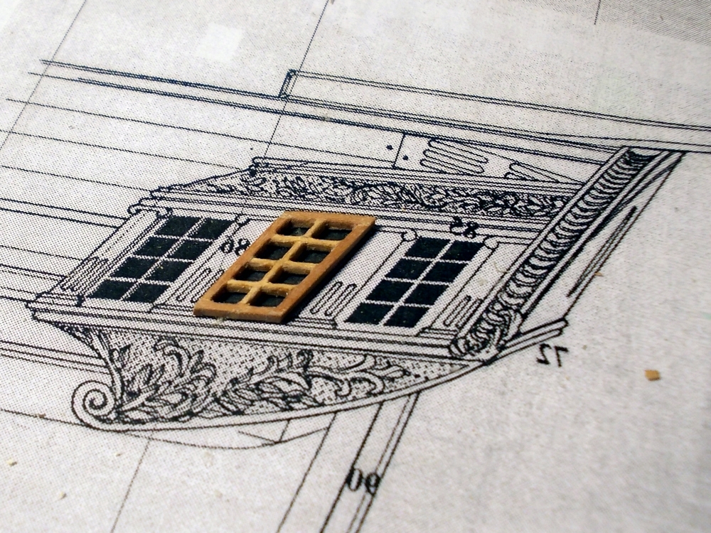
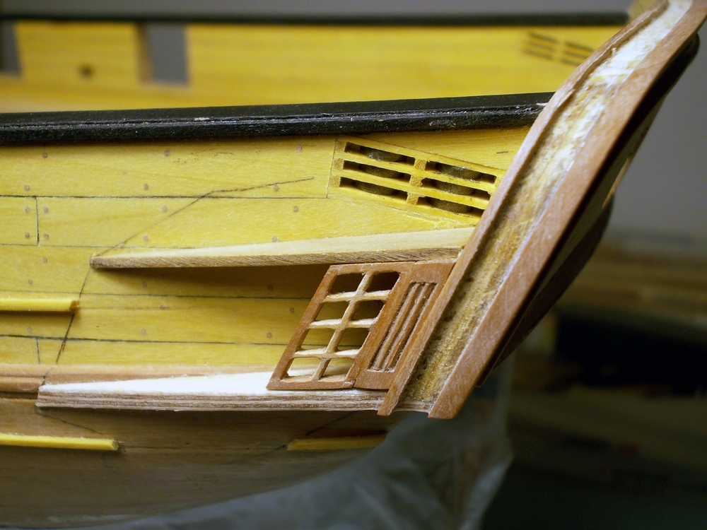
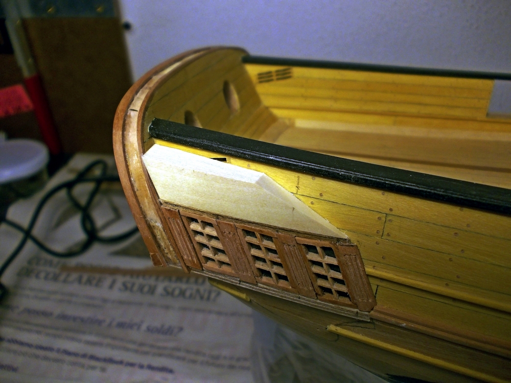
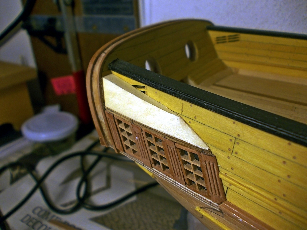
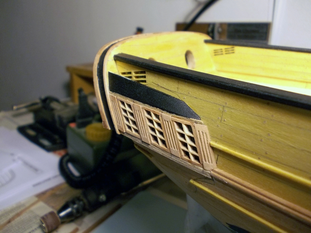
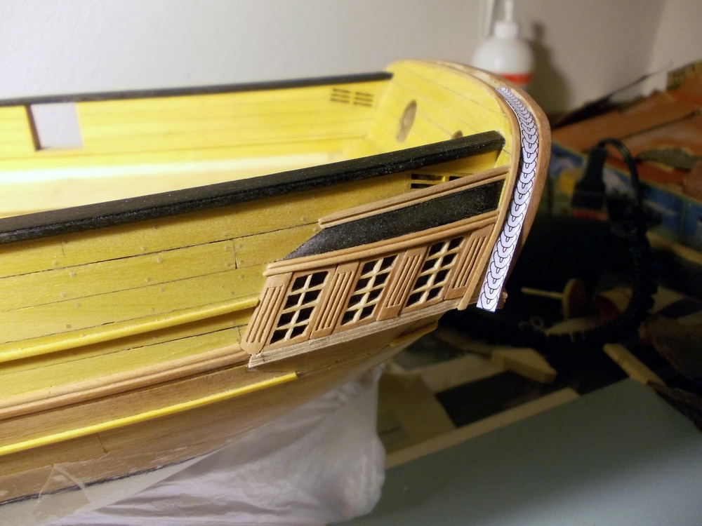
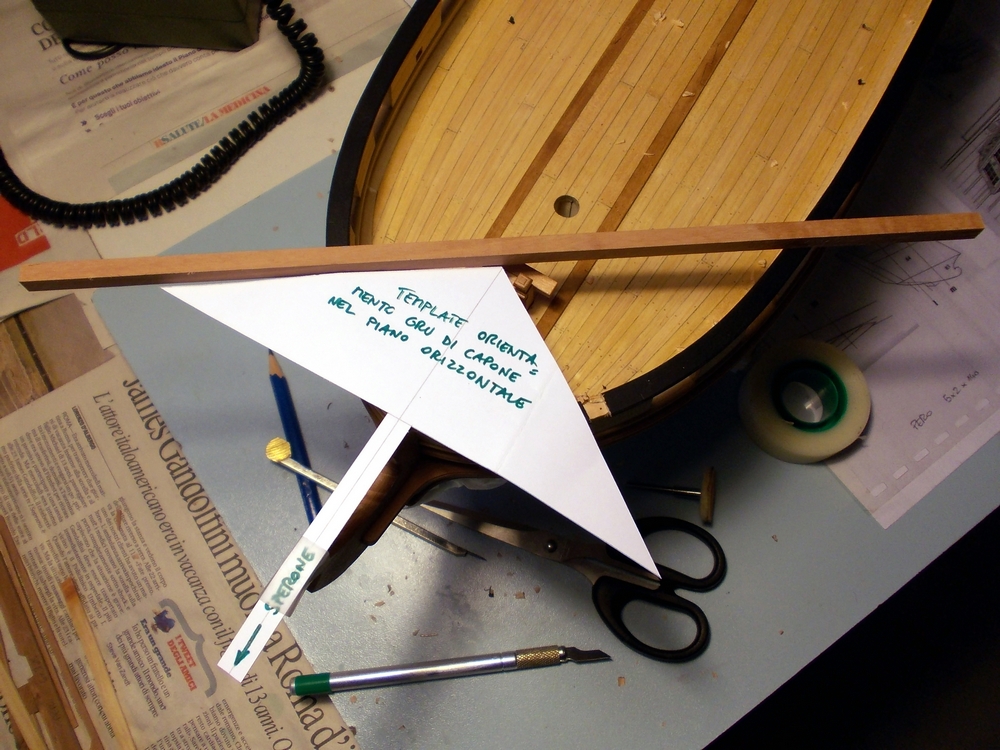
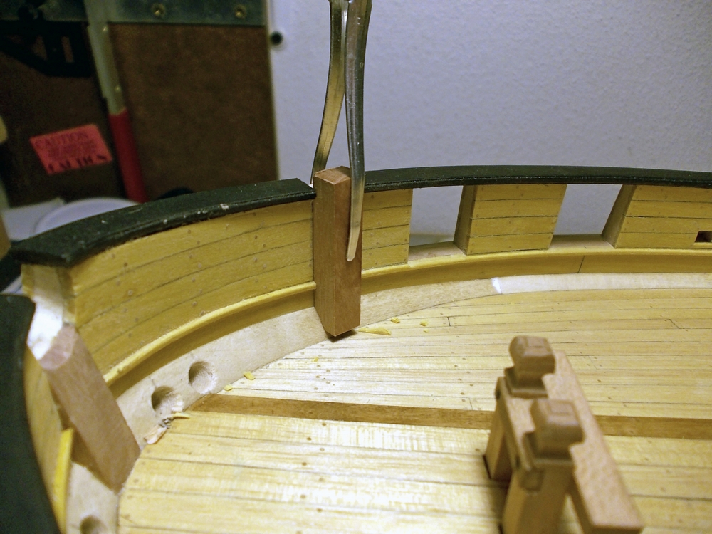
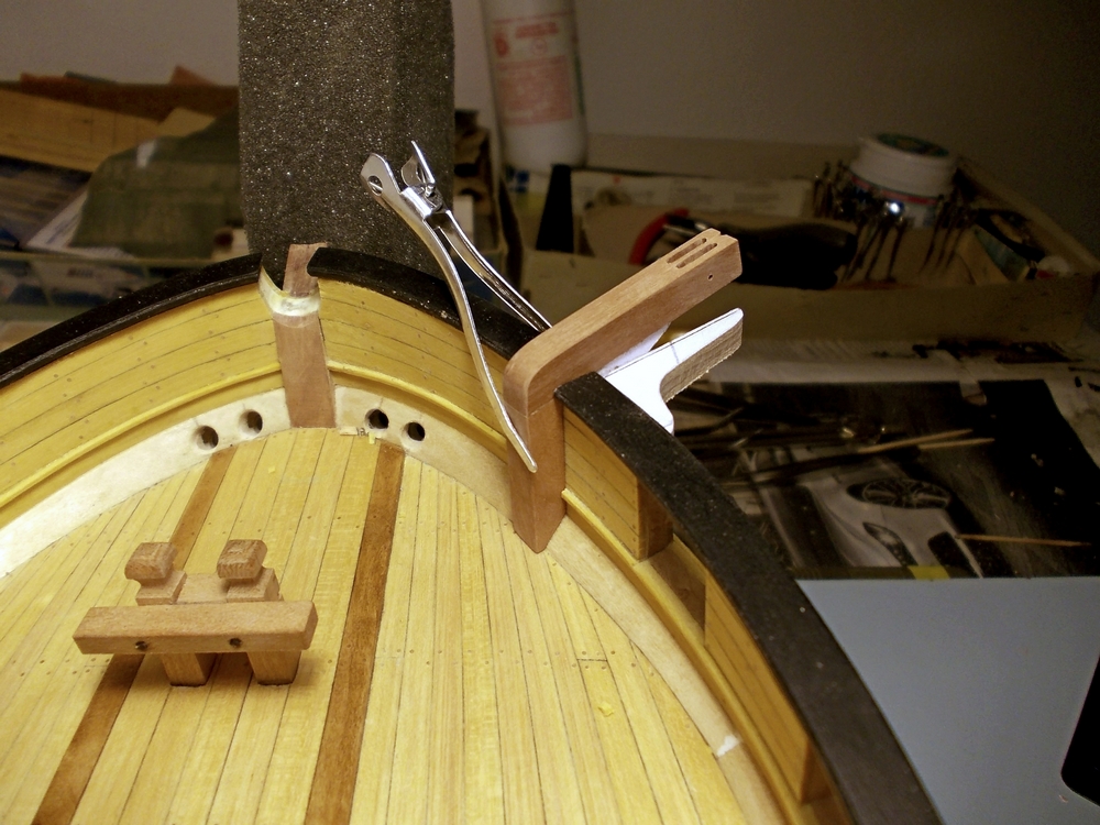
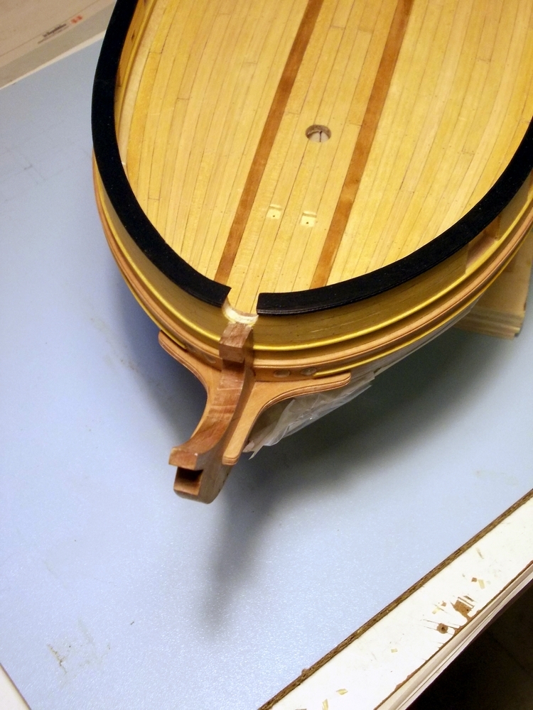
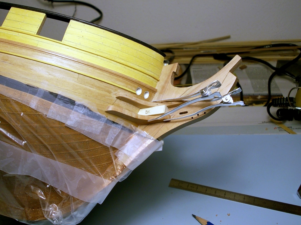
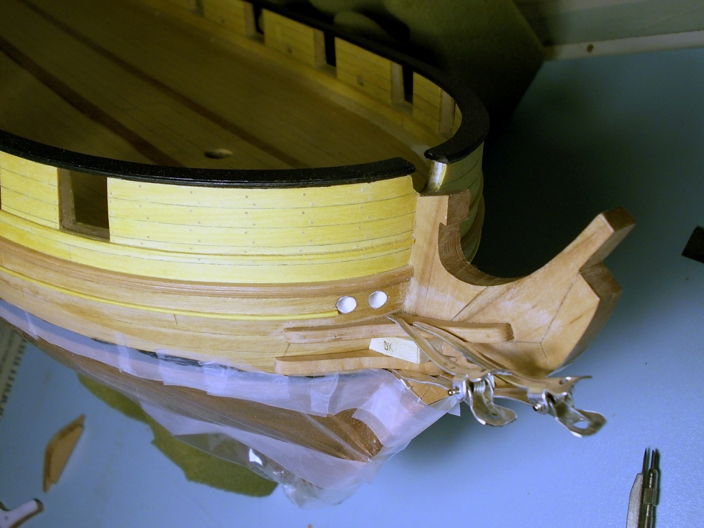
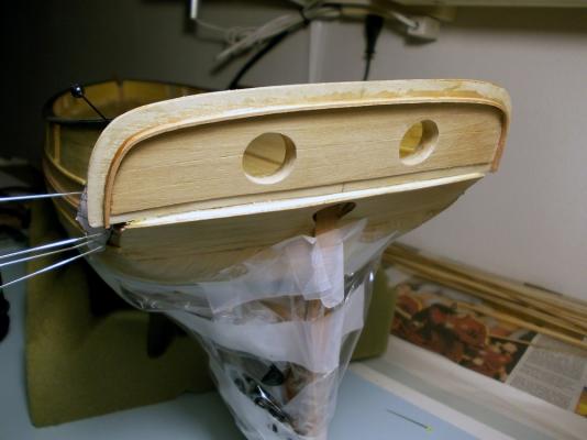
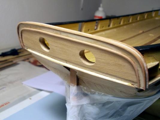
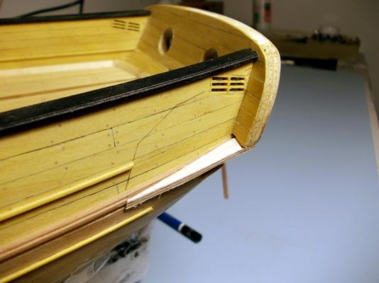
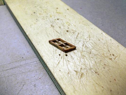
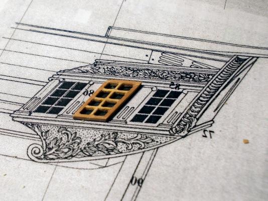
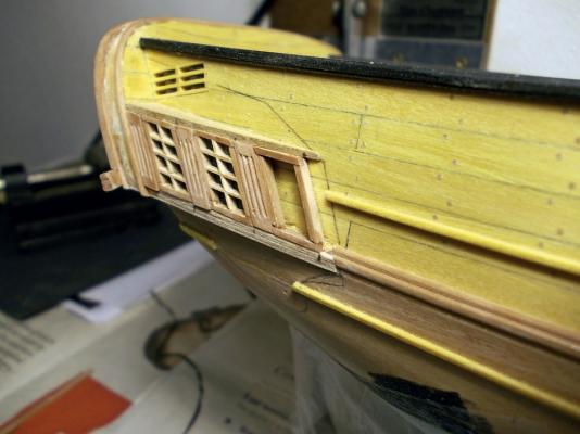
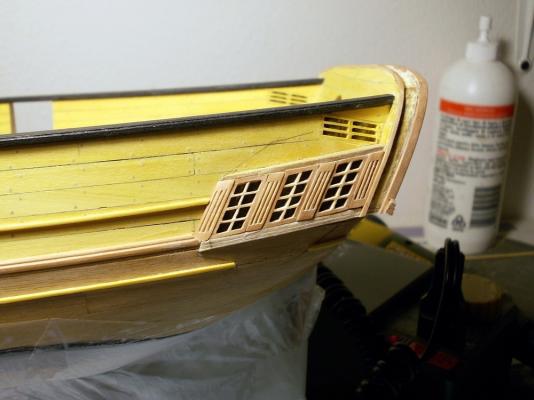
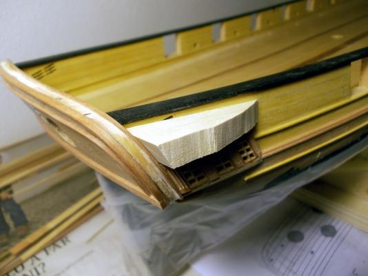
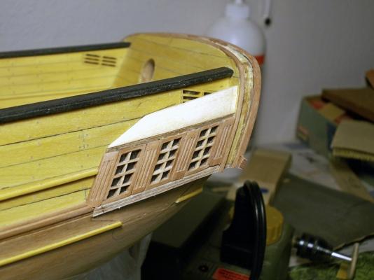
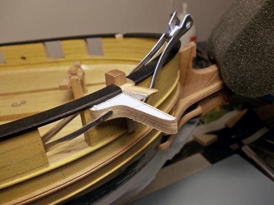
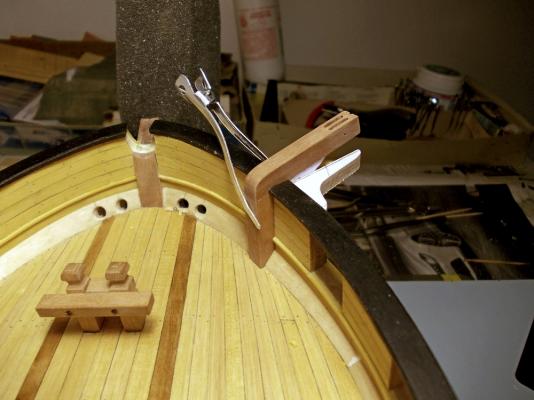
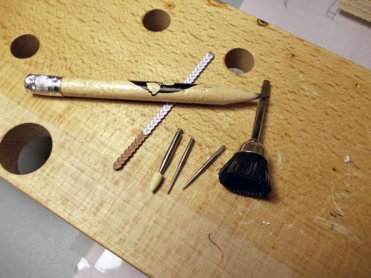
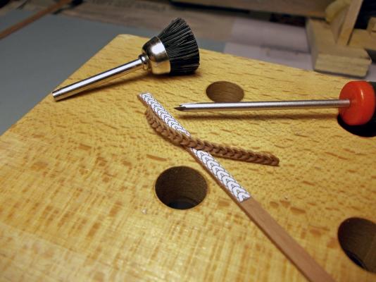
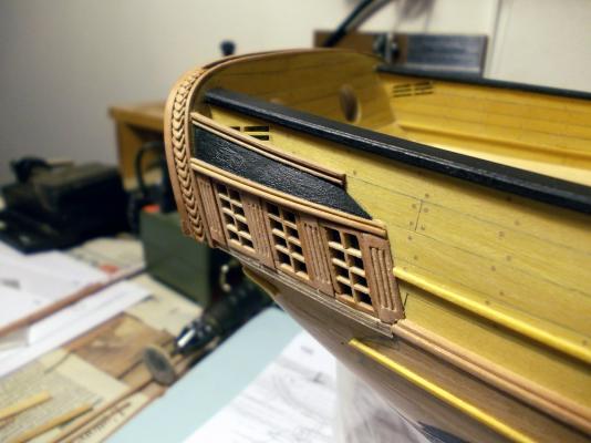
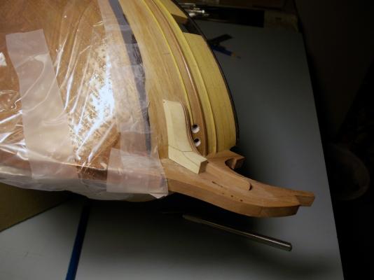
February 1st, 2016 Hi all here I am with a new small update for my French Brig “Le Colibri”. It was a busy 2 weeks period, as the stern windows are very time consuming due to their very small size... but let’s start with order. The first job I started with was the finishing of the transom. It consisted of two phases, the planking and the application of 4 moldings. For the planking I used the same 0.5mm Tanganika veneer as for the main hull. In this case the planks layout is clearly depicted in the Ancre monography, so I quickly copied the plans and pasted the templates to the veneer. Before gluing the planks I had to draw the horseshoe profile in the uppermost part of the transom face, and the profile for the large molding in its lower part. Then the planks application started. After planking, the two round gunports where cut out and filed flush to their lining. I then installed the first of the two moldings delimiting the area where some decorations are scheduled: this is built with a 2x1mm Pearwood strip bent with water and heat. The strip is sitting on the planks thickness, which greatly helps both shaping and gluing. 2mm width is much more than the amount required, as the molding only needs to be raised less than 1mm from the planked surface of the transom: it will be trimmed later. Second phase, I added another Pearwood strip to the rearmost upper edge of the transom. This is 3mm wide, as the extra 1mm is needed to glue the molding above the transom: this way, this will also be the aft molding for the transom upper border that will contain some other decorations. And finally a third 1x1mm strip is glued to the forward-most edge of the transom upper border, thus enclosing the second recessed area for the stern decorations. As already said all these strips have excess of material: after glue was set, they were sanded with a rotating abrasive disk down to the required width and thickness. BTW, I will never stop being amazed by the ease of bending this wood with just some heat, it’s unbelievable! Consider that I had to bend them in horseshoe shape and then edgewise to match the transom profile when seen from above, all in a single piece!! Second task: the galleries. Well, some of their parts are already visible in the above pictures, because I worked in parallel on multiple items while waiting for the glue to set. This was the sequence: The profile of the side galleries, or fake windows as you prefer, is given in the plans. So again I just copied, mirrored and pasted it to both sides to draw the involved profiles. With them defined, I could remove with a scalpel the portions of the three side moldings affected by the galleries: Next I draw from the plans the floor and ceiling profiles for the windows area and transferred them to a thin plywood sheet: 2mm thick for the floor where a wide decorative molding is scheduled, 1mm thick for the ceiling where the molding is narrower. Vertical positioning of the two profiles was quite tricky, as I had to match their slope (when seen from the side), the matcing surface of the transom wings, the large side molding of the hull and the multiple sheaves block. In the end I realized that the only way to get the correct orientation was to fit the floor profile below the transom wings, and not just forward of them. So in the above picture the port floor profile is correctly shown in its final position, while the following picture shows the starboard side with the incorrect positioning. The starboard profiles were only temporarily glued, so I easily managed to remove both of them, rebuild a longer floor profile and reinstall them. As far as the ceiling profile, its rear side is too high and touches the sheaves block with its internal corner: I had to lower it about 1mm at the rear to get the correct slope (seen from the side) and to clear the block with the required distance. Windows then: a real pain in the ...! They are so small and tiny that I found no alternative other than building them one by one by hands: no automatization was possible, nor it was worth, because they are not equal to each other and they are just six. So I cut very thin strips for the contour and the internal frame, using two qualities of Pearwood: 0.8mm thick darker Pearwood for the borders, 0.5mm light Pearwood for the frame pieces. Width (i.e. the window thickness) is 2mm for both and is reduced to 1mm after mounting is completed. This is the first prototype almost completed: it took a whole building session of three hours to get at this stage!! And this is the completed prototype, thinned and sanded, compared to the plans: measures are something about 12x7mm, with backward sloping tenon junctions at all corners. I was satisfied with the result, so started with ‘mass’ production. The pillars are 2.7mm wide, and I chose a slightly different decoration with respect to the plans that, I remind, deal with the Le Cygne brig. Another consideration about the general layout of the stern galleries: in all the plans of the Le Cygne class brigs we managed to find (with ‘we’ I’m meaning JA and myself), there are apparently only two layouts that only differ in the shape of the upper roof. The brig Le Cyclope, which pictures were posted by JA in his buildlog here (http://modelshipworld.com/index.php/topic/7795-hms-guadeloupe-ex-french-le-nisus-brick-de-24-by-jackaubrey-148-scale/?p=242287), shows the second possible layout. Given the total absence of any drawing (so far) for Le Colibri, I decided to stick with the plans. The following is another picture of the starboard gallery at a later stage: the glass, or blind, of the fake windows is simulated by gluing a piece of clear plastic sheet to the back of the window structure. I sanded the front surface of the plastic with very fine (1000 grade) sanding paper to diminish its glossy look, ant then painted black its back side. The port windows and pillars completed: a simple capital is still missing from both ends of the pillars, but the basic shape is complete. Now the upper roof: I took advantage of the skill learned while making the bow cheeks, because even in this case it was just a matter of matching multiple surfaces. This is the starting point, with a block of Basswood cut and sanded to match the hull (on the internal side) and the front face of the transom wing (on the back face). Then the external profile is vertically cut just matching the border of the windows ceiling profile. Also the forward slope is roughly cut, using the profile line draught on the hull side: Next the forward slope is refined, until getting the correct shape, and the upper face is cut following the line draught on the hull: Finally the inside part is cut, removing the material blocking the sheaves block: And this is the roof piece sanded smooth, sealed, sanded again and painted matt black: Note that also the recessed area for the transom border decoration has been painted, in preparation for the next stage. The final look of the port gallery, with the required decorative moldings applied to the roof. A floral decoration is still needed on the roof surface; I have to figure out how to build one sufficiently thin and delicate for my taste. A paper template for the transom border decoration is also evident. As all these jobs were quite demanding, I needed something alternative to relax. So switched back to the bow area and started preparing the pieces for the catheads. First step was to cut the recesses in the gunwales that are needed to house the cathead beam. I prepared a template showing the beams angle as seen from above, and positioned it on the hull centerline and, in the longitudinal axis, using the only reference body that I have already available: the bitt for the bowsprit foot. After cutting the two recesses in the gunwales, I could start with the inner beam: Cherrywood was the choice this time, to match the color I’ve decided for all the deck fittings. I started removing a portion of molding and then shaped the face matching the inside bulwark and the waterway. My scope was to get a tight fit without cutting the waterway, so took my time and adapted the lower surface with continuous test fits and modifications. For the outward side, I had to build a simple jib permitting to obtain the correct cathead angle in the horizontal and vertical plane. The vertical knee is just a dummy for the final knee, whose shape is available in the Ancre plans. The horizontal knee is just a piece of wood cut to the correct angle, with respect to the outboard surface of the bulwark, and resting under the protruding gunwale. To obtain the correct horizontal angle, i.e. with the cathead slightly backward of the perpendicular to the bulwark, I used again the template above shown. Also visible is the upper portion of the inner vertical beam, that I left longer than needed. Last picture related to the cathead shows the completed starboard item. To reach this stage I deepened and sloped the gunwale recess and cut the internal beam flush with the recess, so that the athwart beam could be positioned with the correct angles. Then glued the two beams together, strengthening the joint with a brass pin that will remain invisible. Then completed the job with filing and sanding until getting the final shape. Were the catheads of this type built in a single piece, or by joining two beams the way I did? And in the latter case, was any metalwork visible for the junction of the two pieces? I don’t know, I’ve seen examples of both types... any suggestion? Last job I did, again to ‘relax’ among more demanding works, was to start carving the transom decorations. I evaluated different types of decoration suitable to fill the narrow strip on the transom border, and even considering that the same decoration would have to be used for the slightly larger area on the back face of the transom. I considered simple disks, shells, leaves, had a look in my photographic database of shipmodels...then decided for a sequence of overlapping stylized leaves: leaves and flowers should match the typical environment where hummingbirds (= colibri) live, it looked like a good and logic choice. This is the start of the task, from a 3.2x1mm strip of dark Pearwood. The pencil gives an idea of proportions. The shown rotary tools are my best friends for this type of carvings: I got them from my dentist, as a present after hours of pain and thousands of Euros The two missing tools in above picture are a very sharp cutter blade and a chisel I build from a screwdriver... less than 1mm wide, good handle, very hard steel that keeps quite well the cutting edge. The next picture shows the first strip completed and the next ready to start. The completed decoration has been already bent in two directions and twisted to conform the composite shape of the transom border: the carving makes its easier, together with water soak and heat, but Pearwood is just... And this final picture shows the starboard gallery as it was yesterday evening Regards Fam


-
I would say this is jewelry craftmaship, as these wheels are real jewels! Fam
- 3,618 replies
-
- 6
-

-
- young america
- clipper
- (and 1 more)
-
Wonderful results JA! Have you considered pre-staining the strakes before installation? Fam
- 170 replies
-
- 2
-
-
- gokstad
- dusek ship kits
- (and 1 more)
-
Thwarts = seats for the rowing sailors You might also consider alternating the oar blades and packing the oars in tight bundles seized with ropes Cheers Fam
-
Hi JA may I suggest you not to bevel all the teeth in the frames? The teeth have been designe to house the precut planks, of course they MUST be beveled but as you already understood the frames are very fragile. Nonetheless the amount of bevel is not large and, mainly, it is very confined in a small space...the height of the tooth itself. So you cannot use your usual sanding sticks the way you are accostumed to. I suggest you this aproach, which I already successfully tested in my Knarr (also by Dusek): - bevel just the first tooth, the one close to the keel - glue the first plank (the "garboard" in the later ships) on port and starboard - with the first plank glued, the frames are already a little bit stiffer and able to sustain the tools pressure for beveling the second tooth from the keel - and so on This way you are strenghtening the frames at the same time as you work your way down from the keel. Another warning for you...just in case: the planks are already precut with the required shape, in theory the should be just removed from the sheet, sanded and immediatly glued. Well, this is just theory! Don't know if it was a defect of my kit, but the fit of the planks was very poor, with errors up to a couple of millimeters, sometimes the curvature was incorrect, some other time the amount of planks overlap was unsufficient . I only could use them as templates to cut new ones out from a 1mm thick sheet of wallnut...had to re-build 3/4 of the planks! Nonetheless it was a very good excercise for planking, and a beautiful experience for the klinker type planks. As I've seen that Dusek is going on in this philosophy, I hope they have improved their design or the appreciation for their kits will sunk in very short time!! Cheers Fam
- 170 replies
-
- 6
-
-
- gokstad
- dusek ship kits
- (and 1 more)
-
I don't know why, but after my signature there is still another picture (a copy of one I've posted) that I've not added in the Editor, neither in the Full Editor... the system is doing this by itself Anyway, many thanks to everybody for the likes and the appreciating words Fam
-
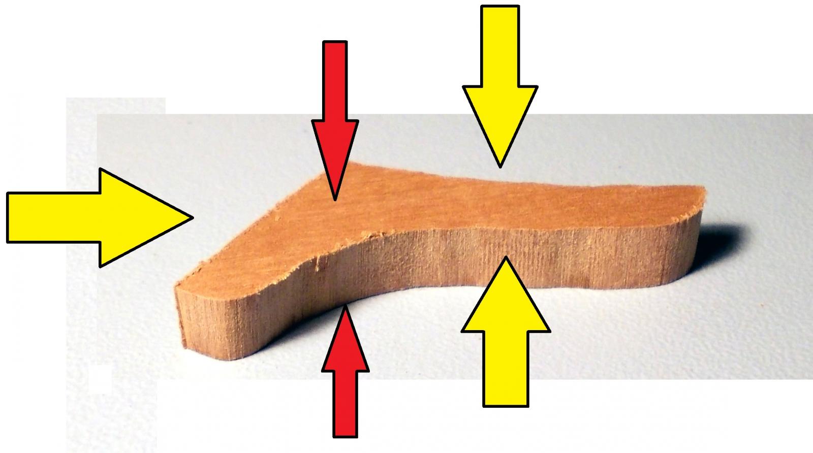
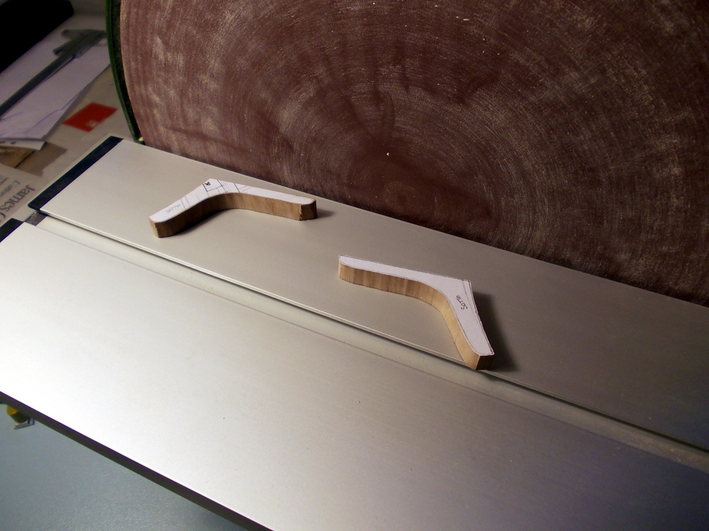
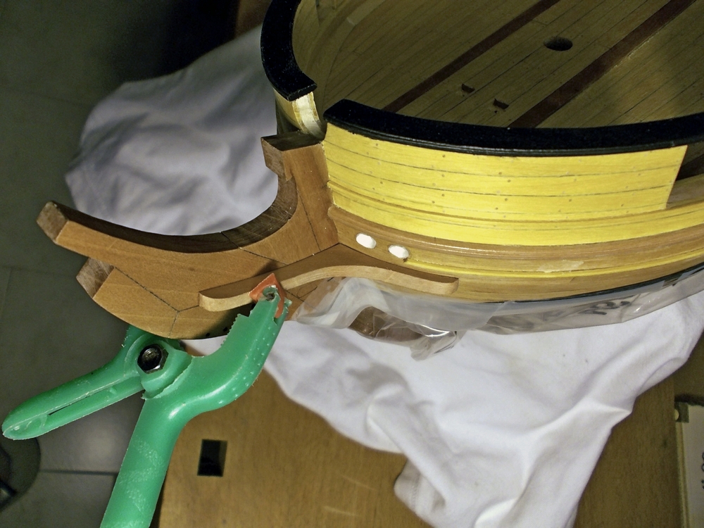
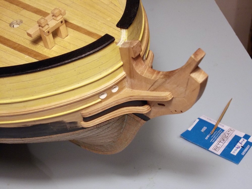
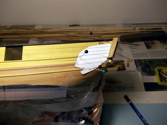
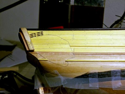
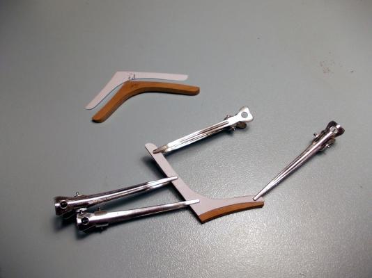
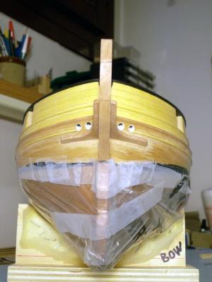
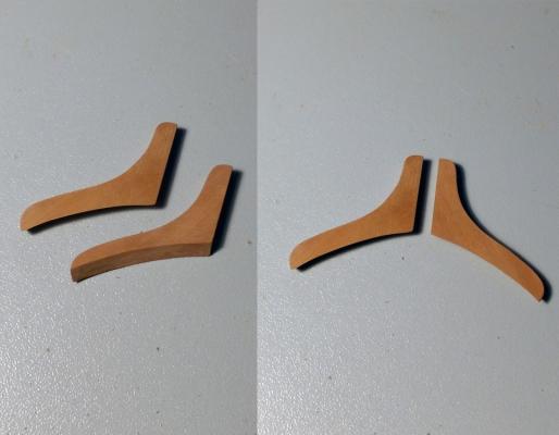
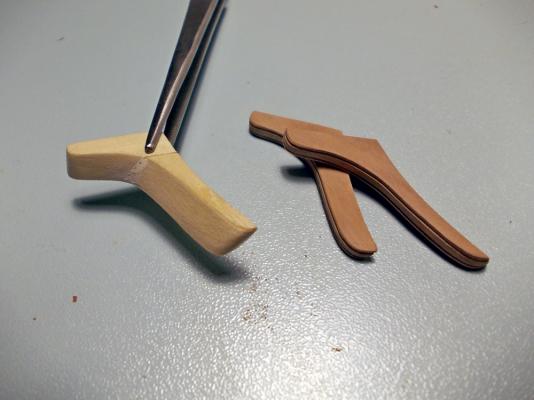
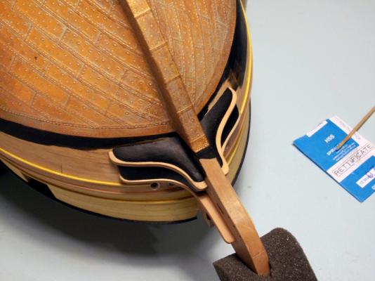
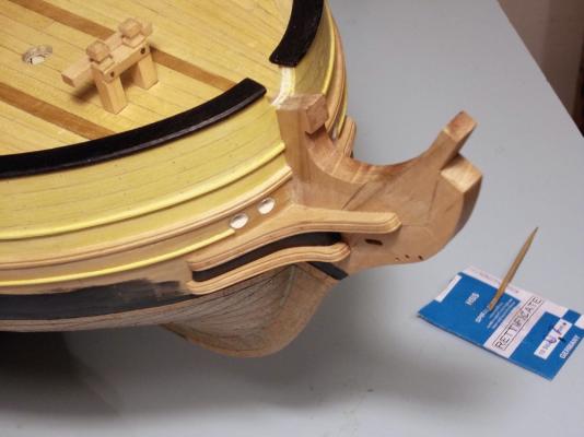
January 15th, 2016 Hi all update about building the cheeks. This may appear a bit too detailed, but I’m also writing to give some guidelines to my good friend JA, who is now behind me in the building ... so please forgive me if I’m tedious. The starting point is a piece, roughly cut from a 6mm or 8mm thick piece of Cherry wood. The picture shows one of the lower cheeks, whose total thickness (including its upward curvature) I calculated to be 4,1mm. I approximated it to 4.5mm, to leave some safety margin, and started from a 6mm thick piece. For the upper cheek, which is longer and with a deeper curvature requiring a 6.6mm thickness, I started from 8mm thickness. It is a complex shape, with 5 surfaces to cut in order to match the hull curves: the inner face, matching the knee-of-the-head: this is flat the aft face, matching the hull curvature the front face, with a curve to be cut according to the plans And then, as the cheek is bent upward: the upper face, that is concave the lower face, that is convex The first three faces are those pointed by the yellow arrows, the latter by red arrows. I had to find a method, a sequence, to get these five curved surfaces. I started gluing the paper templates of the lower face, that is larger due to the slope of the hull. Then I roughly cut the along the template lines with the scroll-saw. The inner face was the simplest to obtain, thanks to its flatness, so I got it with the disk-sander. Next I decided to reduce the thickness to the required value, and used a mill mounted in the press-drill. This way the thicknesses were reduced to 4.5 and 6.8mm, respectively. Then I went with the upper and lower curved faces: I marked on the three lateral faces the material to be removed, and then used a sanding drum like shown in the following pic: The next picture shows one upper cheek with 4 completed surfaces: the only still missing is the one matching the hull surface. On this side, I left a 3mm abundance of material, and also left the longer arm 5mm longer than required, to permit further adjustments. This is not evident in the picture, which shows the first attempt that resulted too short, and sadly flew to the scrap pieces box! Again, I used a template with the cheeks profile cut out to define their correct upward curvature. Matching the aft face was really a pain: it must be done very slowly, tenth by tenth of millimeter, with continuous fit-tests and adjustments. The two following pictures show the first, port, upper cheek almost completed (the long arm is still too long) seen from below and above. Completion of the first cheek, including the wrong discarded piece, required about 3 hours. After the first piece was completed, I drew two new templates for its upper and lower faces. Then mirrored them and glued to the rough piece for the starboard cheek. Using this trick, I built the second cheek in not more than 15 minutes! Final touch was the decoration of the front faces: I used a scraper and will not describe again the method, widely discussed and used here on MSW. So, here they are: the upper cheeks completed and permanently glued: Before starting with the lower cheeks I had to find their correct position, i.e. distance from the upper ones and slope angle both in the side and front views. So I built a chock the same size of the filler piece using Basswood that is much more easily carved than Cherry wood. These chocks lay against the flat knee-of-the-head surface, match the curved underside of the completed cheeks and the hull surface, and are as long as the short arm of the filler pieces. With these pieces fit and temporarily glued (3-4 spots of stick glue), the procedure was repeated for the lower cheeks. A bit quicker, thanks to the first experience, but still a time consuming process. The following pictures show the two pieces completed and permit to appreciate their complex 3D curves and bevels. But before fitting the lower cheeks I needed to complete the building of the filling pieces: as written above the chocks shape was already very close to the forward half of the fillers. Considering that they had to be painted, I decided to try the simple addition of the missing arm instead of re-building them from zero. This is the first attempt, only roughly shaped: The pencil marks are obtained using lower cheeks as templates, which helped a lot in getting the final shape. Similar lines were drawn on the fillers upper face, using the upper cheeks as guiding template. And finally here is the first fille piece completed, with the joint between the two halves quite evident but smoothed using wood putty: No need to continue with the wash-cant pieces, the method was again the same. So I’m posting the final result seen from different points of view: The last 4 pictures above were taken after the problem I had with copper weathering (described in the previous post), that caused the starboard lower cheek to be discarded and re-built. Job completed! The next will be the base structure of the stern galleries and transom decoration... stay tuned Cheers Fam


-
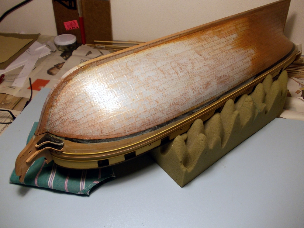
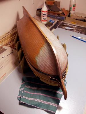
January 11th, 2016 Hi all before going on, I’d like to add some more details about weathering the copper plates. The reason comes from the need I had to repeat the chemical treatment, because I destroyed several plates while building the cheeks ... so I’ve taken a couple more pictures. The following shots show clearly what anyone has to expect after a while of application of the vinegar-salt solution: The white patina is very evident here, but nothing to be worried about: it is a standard phase of the copper oxidation with vinegar-salt. I’ve prepared the solution with about 50ml of white vinegar (standard cooking product), 1cm deep into a 15cm diameter pot. Then started heating it, while at the same time adding full spoons of normal cooking salt. After each spoon added, I continued mixing well until the entire amount of added salt was melted. Then added another shot. When I noticed that melting was becoming more and more difficult and the vinegar was almost boiling, I added one more teaspoon of salt, mixed again and removed the pot from the fire. I recommend using an inox steel pot, to avoid any side effect from solution-metal reaction (and also any concern from the admiral!!) and to activate the aspirator fan because the vinegar vapors are quite irritating for inhalation (if not dangerous, I’m not sure). Of course the new copper was prepared in advance, with steel wools sanding and acetone degreasing (same as for the old plates). Scratching is needed because some copper producers use to apply a coat of protection material to keep the copper shine, for decorative reasons. After preparation, I started immediately applying the solution to the copper. I noticed that the solution tended to remove the old weathered patina, which I didn’t expect. So I tried to blend the new treatment area into the old area... well it ended with almost the full port side re-treated and the bow portion of the starboard side, as clearly visible in the pictures. Nothing happened to the new plates, which was quite weird because on the first time I used this method I had immediately noticed a change in the copper shine. So continued application of the solution, more and more and more... but still nothing! I was in despair, so decided to stop for a while and let it work while having dinner. When I went back to the workshop, the effect was as shown above. So attentively started to neutralize the acid solution with tap water applied with a rag, that removed 99% of the white patina and left only the weathered copper plates I was expecting!!! Only a slight amount of patina remained in the recesses of the copper plates, the joints and the nails, with an effect that I like very much. Four other notes: to apply the solution I used an old rag, initially used as a brush with long stokes and then just tapping it, wet of solution, on the copper surface. A sort of foam was left on the copper surface while tapping. while the solution was initially removing the old patina, the trickling down excess liquid became green with the same color of copper oxide: be careful with it, protect the wood because this liquid can stain the wood (which incidentally occurred to my just completed cheecks ... disaster!!! ) while the solution was cooling down in the pot, some more salt sinked to the bottom. This confirms that the solution is 100% saturated of salt, as it’s concentration depends from temperature (as far as I recall from my studies of chemistry and technical physics) the weathering layer, or copper oxide, is quite stable and strong after a few days have passed: removing just by scratching with the fingers is not possible And finally: I have no clear if oxidation is continuing even after neutralization of the solution or if the oxide layer is already a self-protection for the metal, like for Aluminum. I suggest neutralizing the acid solution as much as possible, and then I will wait to see what happens in... a minimum 6 months’ timeframe. That’s all for today (cheeks reconstruction time ), I just tried to report all my observations in case they might be useful for anyone else. Cheers Fam

-
Hi JA you might be interested in this, if you don't know yet: http://home.online.no/~joeolavl/viking/borgundknarren.htm Regards FAM
- 170 replies
-
- 2
-
-
- gokstad
- dusek ship kits
- (and 1 more)
-
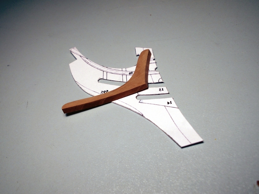
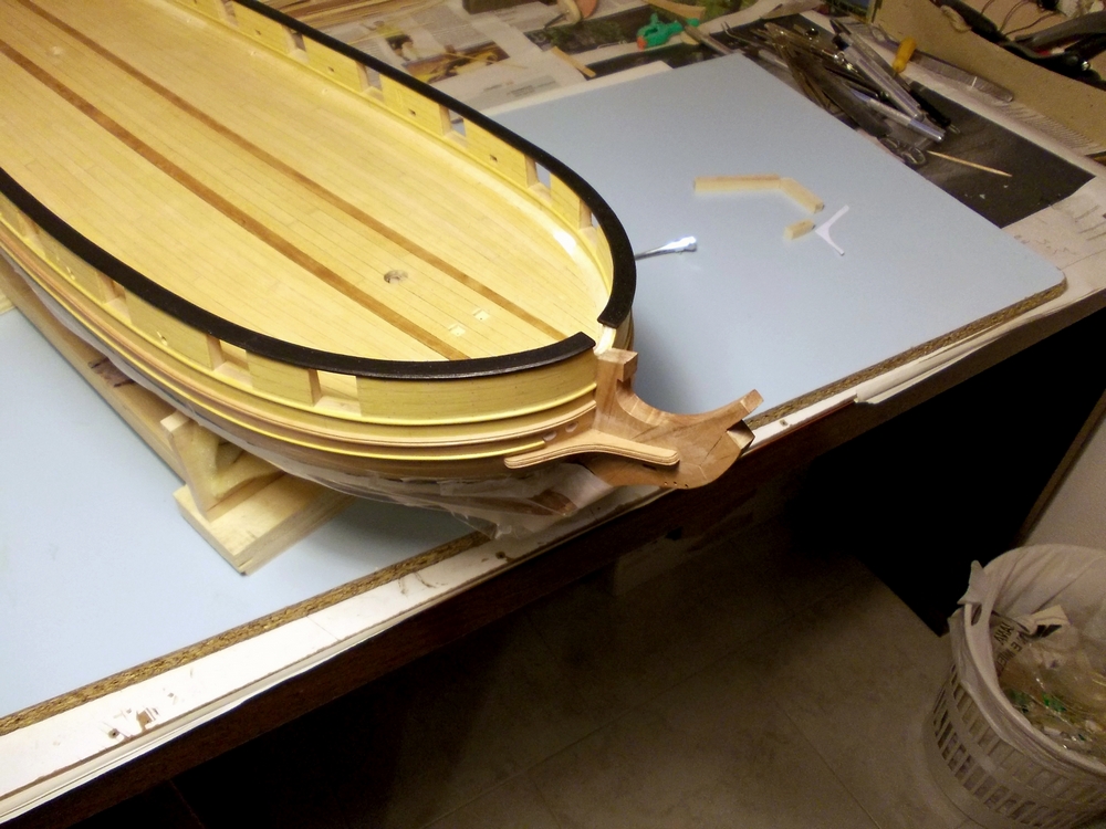
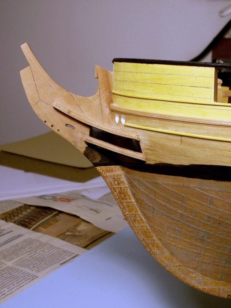
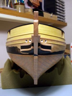
As many can image, there was an email exchange between my good friend JA and me. I am at a point, in the building sequence, where a decision is needed about several items: - type and size of the figure-head - type and shape of quarter galleries These two issues had several variations within the so called "Brick de 24 lbs" class of ships in the French Navy. The size and shape of the figure-head, if any, would affect the shape and size of the cheeks laterally supporting the knee-of-the-head, mainly the lower one. So I decided to choose the ship I am building within the array described by JA in one of his first posts. All of them were bricks captured by the Royal Navy and re-commissioned under the Union Jack flag. This fact permits making some other important decision, affecting the layout of the ship, such the technology of masts and rigging. The HMS Colibri (hummingbird), ex-Le Colibrì, had an interesting history in RN service (source Wikipedia): "HMS Colibri was the French naval Curieux-class brig Colibrì, launched in 1808 at Le Havre. On her way to San Domingo in 1809, with a load of flour and gunpowder, she captured and sunk two British brigs, the Hannibal and the Priscilla. Then she met, off Barbuda, the British HMS Melampus: in the engagement had 3 men killed and 11 wounded. She was then took into the Royal Navy under her existing name. Her time in British service was spent on the North American station based in Halifax, Nova Scotia, still in company of the HMS Melampus. During the War of 1812, Colibri served mostly in blockading the American coast and capturing privateers and merchant ships: - the american Fortuna, on 9 Oct 1810 - the american slaver Carolina - alias spanish Atrevido -, on 15 March 1811 - the spanish Empressa, co-captured with HMS Little Belt on 25 Mar 1811 - the american privateer Gleaner, on 23 Jul 1812 - two american vessels, Bream and Catherine, and a bark their prize, on 24 Jul 1812 - the american Emulous, after she was inadvertently grounded by her crew, on 2 Aug 1812 - the american privateers Polly and Buckshin, on 11 Aug 1812 - the schooners Regulator and Dolphin, on 12 Aug 1812 - the american vessel John, co-captured on 13 Aug 1812 - the american ship Monk, on 23 Aug 1812 - three more vessels on the beginning of 1813 (co-captured), the american schooners Scyron (16 Jan) and American Eagle (18 Jan) and the swedish brig Hanosand (13 Feb) - not less tha 10 merchant ships (brig Commerce, schooners Female, Minerva, Portsmouth, Eliza, Nancy, Sampit, Wingaw and Gustava, ships Minerva and El de Patado in Cortes) between March and June1813 She foundered in 1813 after grounding on a sand bank in Port Royal Sound, South Carolina, but without loss of life." I have decided to build it with French type masts and rigging because ... well (1) because I've already built two 8pdg long guns, which were part of her weapons during service in the French Navy (the RN changed them into 2x 6pdr long guns), and the (2) because JA has decided to show the type of vessel with British masts and rigging. The Hummingbird is a small bird, with a small body, long pointed wings and a long beak... all in all I think it will be sufficiently easy to carve the figure-head from a block of wood, as my carving capabilities are very limited. More, it can be shown with a layout not too different from the cygne of the Le Cygne ship, and I expect this to ease my carving work in some way. About the quarter galleries, the brick de 24 class had two significantly different shapes: one with backward sloped roof and another with pointed roof. As this issue affects the position of the multiple sheave-blocks in the aft bulwarks, that I've already built, my choice will be obliged. On the historical side, we have not found paints, nor drawings, nor plans showing this ship: so I feel quite free to decide how to build these two details which have a heavy impact on the final look of the hull. Stay tuned Fam

-
Quick and efficient, as always!! Thx Dirk
-
Hi all may anyone explain me how to change the title of the BuildLog? Thanks Fam
-
Now you have no more excuses, you must start making wood dust :D
- 170 replies
-
- 3
-
-
- gokstad
- dusek ship kits
- (and 1 more)
-
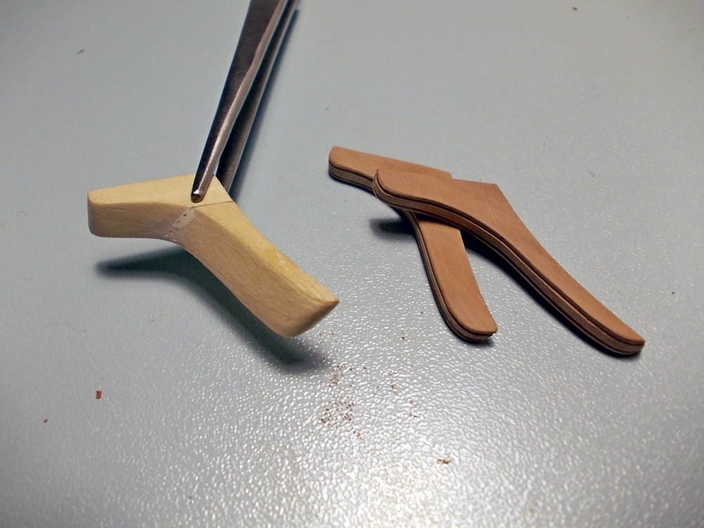
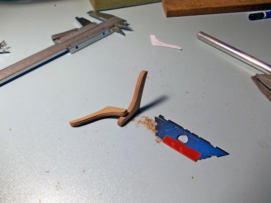
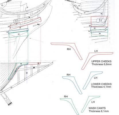
December 29th, 2015 Before starting making wood dust for the cheeks, I had to find the size of the wood blanks to start from for every piece. This below is a sketch from the plans: the parts I’m dealing with are those numbered 11 and 12 (the cheeks), 14 (the wash cants) and 15 (the filler piece between the cheeks, the knee-of-the-head and the bow). The plans provide a side view (from starboard), a front view and a plain view (from below) of the entire assembly: as the pieces are sloping upward to the front and are shown all together, finding their size and shape is not easy. In the sketch, three rectangles (red, green and blue) are visible in the side view: they are the side view, i.e. along the thickness, of the three blanks I will start from. The length of each rectangle is also the real length of the pieces, which is slightly longer than the length shown in the plain view due to the slope of the pieces themselves. In the plain view from below, the shapes of the pieces are more or less apparent: nonetheless they are all overlaying, so it is difficult to find the detailed shape of each part... it must be deduced with some guessing and using the width of each piece as shown in the front view. So in the plain view I’ve draught the three overlaid parts in different colors, using the existing lines from the view and the width (in the vertical direction) measured from the front view. Then I’ve separated the three lines and copied to the right: their length is not yet correct, so I stretched each profile in the horizontal direction to match the correct length as measured in the side view... just a matter of 2%, but still visible. Of course this operation is also partially changing the shepe of each piece on the edge that matches the bow curvature, but I’ll take care of this leaving some abundance of material on this side when cutting the parts from the blanks. This abundance is also needed to adapt each piece, on this edge, to the slope of the hull at the bow. I will tell more about this later, with the parts in my hands. Finally, I just mirrored horizontally the three lines to get the three profiles for the port side. In the sketch I also noted the thickness of the wood blanks. I’ve not talked about parts n.15 yet: they are simply too difficult to deduce from the plans, so I’ve decided to carve them directly on the model after fixing the upper cheeks. With these measurements done, I’m now ready to make saw dust! The sequence will be: upper cheeks, fillers, lower cheeks and wash cants. Cheers Fam
-
Ah ok, now I've got it! I'll think about it, but I really like the color of oxysized copper...it depends at what level of brown to stop it ;-) Cheers Fam
-
Thank you Dirk I've found maybe some similar products but they are all in the category "anti-oxydant protections" for copper, brass, alluminium and other metals...all promising to definitely stop the natural build-up of oxide which is the opposite of what I want. I also found a wax, that is giving the same effects with semi-matt finish... I'm not sure if the scope is to protect the copper plates from the effects of manipulation, or to stop further oxidation Fam