Fam
-
Posts
185 -
Joined
-
Last visited
Content Type
Profiles
Forums
Gallery
Events
Everything posted by Fam
-
 Hi all, and ciao Sergio my friend! Yes I'm still alive, but unfortunately I had to stop the works on my Brig being too busy with another family project... I hope I will manage to resume my shipyard in short time, I'm missing it so much... In the meanwhile I send all the members my best wishes for a happy and prosperous New Year Cheers Fam
 -
Thank you Dirk! I'm missin but still progressing at a low pace
-
April 29th, 2016 No words ... just emotions to share Fam
-
Johann you have done this so many times now that it seems a Ford or VW factory, not a modeller workshop! I have three boats for my Colibri Brig, if you volunteer ... Fam
-
Super carving Igor!! I also like very much the weathered effect! Fam
-
Pewter painting
Fam replied to S.Coleman's topic in Painting, finishing and weathering products and techniques
I used Humbrol enamels for my 9pdr guns, then polished with pencil graphite and a rotating brush ... good looking in my opinion, but depends on personal taste Fam -
I think it's correct, RMC: you should start from the bowsprit laying the collar against the stop cleats, then go down and pass the rope through the gammoning hole, keepeng it as much forward as possible. Then up for another loop, with the rope laid forward of the previous loop. Then down through the hole, with the rope laid aft of the previous loop, and so on.... The loops around the bowsprit should be eight to eleven, depending on the period and class of ship. In the end, the rope coming down from the bowsprit is lashed with several loops at the middle of the gammoning, where the ropes cross to each-other, and seized. The loops of lashing should be eight to ten, depending on the period and class of ship. Good job indeed! Fam
-
This is really excellence!! My compliments Fam
-
Thank you all for the kind words and the likes, I appreciate! A
-
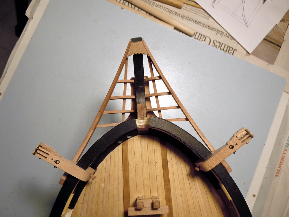
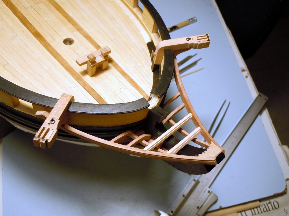
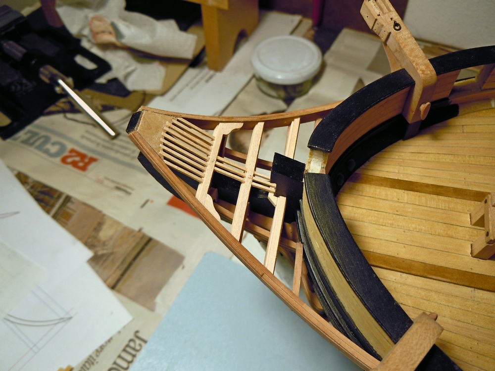
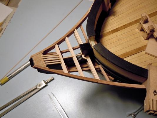
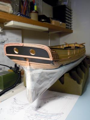
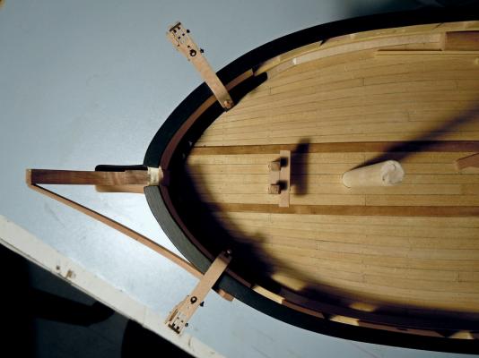
April 8th, 2016 Hi all another quick update about the head-timber works. The third couple of timbers is installed and the lower rail is being test-fitted in the next picture. Note that I had to complete the finish of the three head-timbers in their outer face, for the portion between the upper cheek and the rail, because the latter will obstruct the accessibility to this area for finishing. Therefore I glued a narrow strip of paper, blackened with a felt pen, inside the scraped molding and then re-touched with black acrylic paint to match the bow finish. Here, in the two following shots, the two lower rails are completed and definitely installed. They are monolithic, i.e. built in a single piece, because their size and curvature are smaller and I thought they could be obtained from a single piece of wood. Matching the rail with the three existing head-timbers, with the bow (between the hawse holes) and with the main rail was another “pleasant” task And finally the fourth head-timber is completed and installed: it sits on top of the lower rail (where it touches the bow surface) and is connected to the main rail. All timbers are finished with the black strip on their outer face. Forward platform After completing the lower part of the ship’s head, I have switched to its upper side ... what I call “bowsprit deck” or “forward platform” (pretty sure the name is another, but I don’t know the correct English term). Several cross timbers are laid in athwart direction connecting the two main head-rails. They are longitudinally positioned close to the head-timbers above described, but not precisely overlaid: there is a small shift forward and aft of the two forward-most timbers, to leave space for the bowsprit gammoning. The timbers are intended to support a series of fore-and-aft smaller timbers (or “ledges”?), thus creating a sort of grating, or something that reproduces the carlings-ledges structure of the decks but with the scope of a grating. Connection among the “ledges” parts and the athwart supports should be done with a series of recesses (notches) 1mm wide and 0.9mm spaced apart to each other, like visible on the wedge piece at the head-of-the-knee that I’ve already fixed. The more proper way of doing this job is probably drawing reference longitudinal lines across the athwart beams and then cutting the teeth, with a sharp chisel or cutter, on their fore and aft upper edges. I thought that this method leaves large space for alignment imprecisions, any error in cutting the recesses would reflect in a deviation of the ledges from the F&A direction and from their parallelism. So decided for simulating this method by using instead the method shown here on MSW by Alexandru (Guraus’s buildlog of HMS Victory). I built a step on the fore and aft upper edges of the athwart beams by overlaying two pieces: the lower is 3mm wide by 2mm thick, the upper batten is 2mm wide by 1mm thick: the resulting beam is a 3x3mm timber with two continuous 0.5x1mm steps along the upper edges, which will house the ledges timbers. In this way I will be able to take care of their correct alignment and spacing to each other. The following picture shows the first two cross-beams installed: the steps are visible on the fore edges. Choice of material for the entire forward platform is a lighter shade of Pearwood (Swiss pearwood from CrownTimberyard company, great stuff!!), contrasting with the darker shade of the lower structures. Once again, I couldn’t be happier of my decision to buy a disk sander (Proxxon TSG250/E in my case): once the proper angles needed to match the rails with the beams are found, with some trials, then obtaining the correct fitting for all the cross-beam timbers with the disk-sander is easy and fast, just a matter of few seconds! No need to say I strongly recommend this tool. Here below the third, and last, cross-beam is positioned: it is longitudinally positioned so that it interferes with the stem, that seemed a bit weird to me. But after checking and measuring on the plans and verifying on the model, and then double-checking and measuring again, I got to the conclusion that its position is correct … or better it is compliant with the plans (supposing they are correct). The problem with this position is that the beam, apart from crossing the stem, is not able to support the longitudinal grating. So I added another small piece just forward of the stem and connecting the two parts of the beam: probably not the correct solution, but I could not imagine another way out from this impasse. The building method for this cross-beam was the same, simply divided in two parts. The first 5 longitudinal parts of the gratings (ledges) are also installed, to demonstrate the concept. They seem to be slightly not parallel, but it is just an impression from the picture: I ensure they are parallel! And here again the forward platform at a later stage, with more ledges installed and two of the knees connecting the beams to the rails installed: The knees are notched to match the beam step, then I will cut the recesses for the ledges in the after edge of each knee. Finally a shot from the opposite side of the ship: the stern transom is finished in matt black and the moldings and decorations pop-out much more evident. I like very much the way light reflects on the Pearwood leaf decorations, giving them different shades of color that are only due to different orientation of the leaves. Painting of the counter down to the second molding is not yet complete. That’s all for today. Best regards Fam


-
Cutter Cheerful 1:48 by rafine - Finished
Fam replied to rafine's topic in - Build logs for subjects built 1801 - 1850
Hi Bob I just caught up with your build log, after having read you first posts some time ago I forgot to mark it as 'follow this topic' so missed all your more recent updates. I wasn't aware you have almost completed the beautiful Cheerful, it's really awesome: I like everything of this little boat and the crispy way you have built it! So instead of hitting the 'like' buttons I prefer telling you directly: you did a great job! Thank you for sharing Fam- 525 replies
-
- 3
-

-
- cheerful
- syren ship model
- (and 1 more)
-
Thank you so much Johann, I really appreciate! You already know, you are my reference for learning so many how-to-do items and I consider you my teacher I just watched at your videos on youtube... they are astonishing! A liked a lot the choice for the side music...it is the original from which the violin-cello duet between Jack Aubrey and Stephen Maturin is derived, isn't it? The last shots of 'Master and Commander'..one of my preferred movies Fam
-
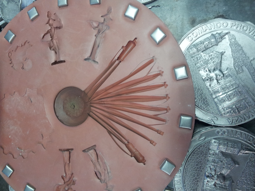
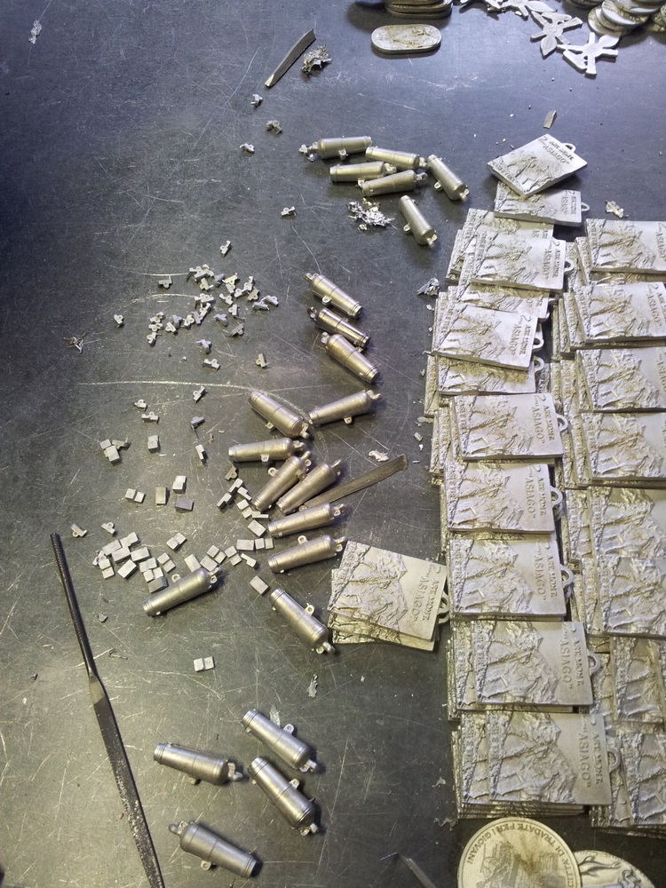
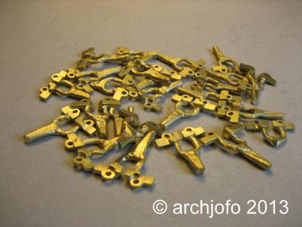
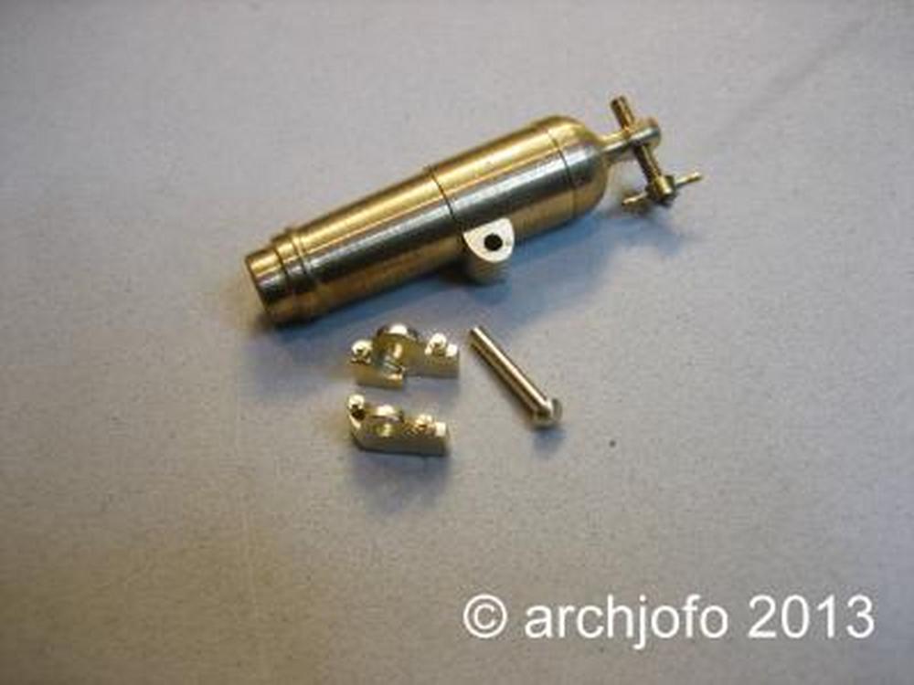
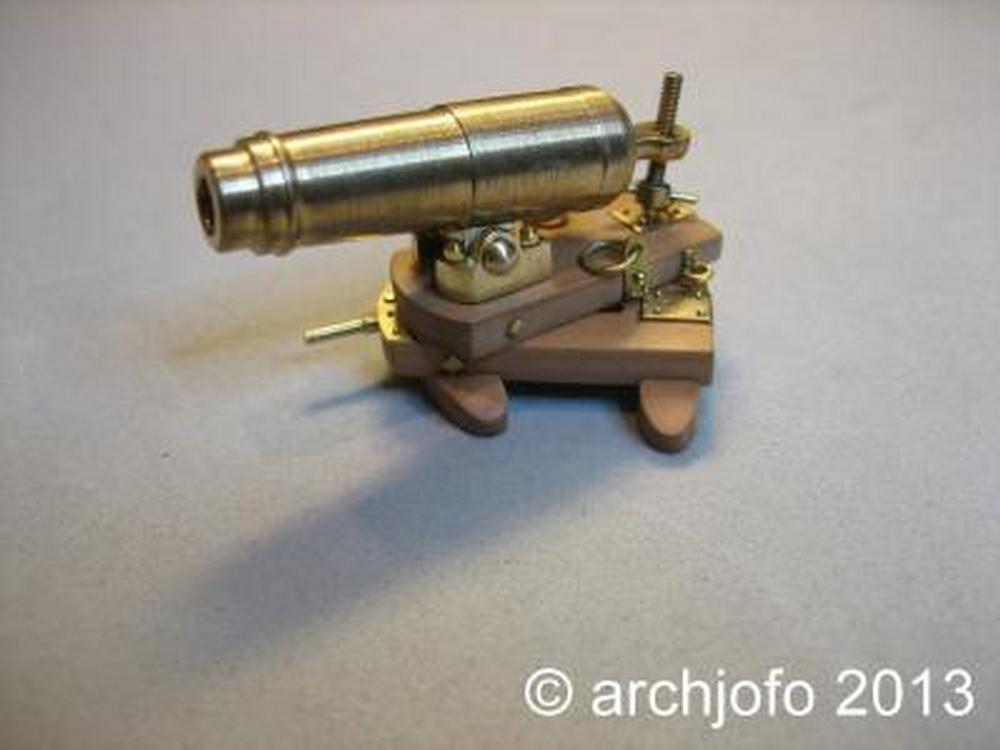
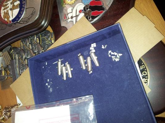
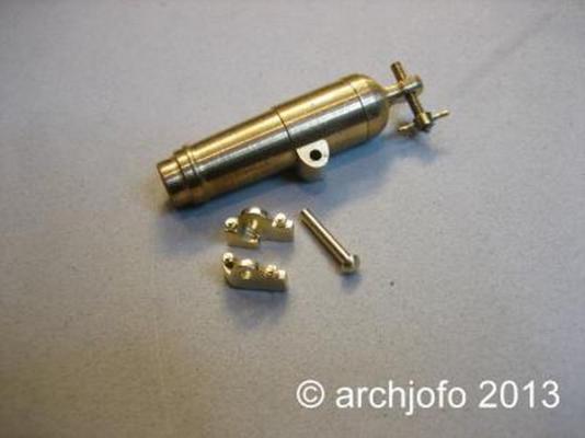
For those who don't have access to the German forum where Johann is posting his work, I show here three steps describing what I'm trying to obtain (Johann if this is disturbing just let me know and I'll remove the images immediately): - cast support parts for carronade barrel - unassembled parts - the completed carronade All his pieces are brass, either lathed or cast. I was not so lucky, so all my parts will be cast in pewter. The final finish will be in gun-metal paint, polished with some lead pencil dust to improve the metallic look. The 9pdr long gun pictures I posted some time ago show what I mean. I'd like to highlight that the design of my barrels seem to be exactly the same of Johann's, but I only referred to Ancre plans: probably the weapon was the same type for both ships, regardless of the different years of building. Also note how the lower part of the carriage has no wheels, and carronade training is done by rotating the upper sledge ... this seems to be a little bit weird, but I don't have the knowledge to contest this layout. Cheers Fam

-
Yes Johannes, I did the same: 3 couples (LH+RH side) of supports, one for the French carronade, the other for the British carronade and the third as a spare. I hope I'll manage to get all the parts (two barrels plus 3 supports couples) casted in one shot, to be repeated 15 times. Unfortunately yet didn't get any contact with the artisan who will manufacture the casting, probably because of Easter holiday period. I will try again next week at the end of the short holiday Happy Easter to everybody Fam
-
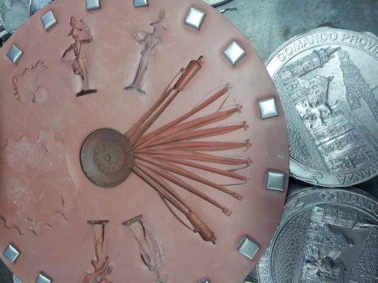
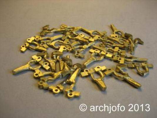
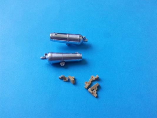
March 22nd, 2016 Hi all, just a very quick update about the 24prd carronades: the masters for casting in pewter are finally ready. The design is exactly taken from the Ancre plans, giving the first master (below in the picture). Then my good friend JA asked me to have something slightly different, because his HMS Guadeloupe will be shown after recommissioning with the British Royal Navy. So, using as examples a couple of drawings he sent me, I've got a second master modified in several details to represent a carronade more in the British fashion. The total size and general layout are about the same, but diameter is larger, there are additional and more evident reinforcement rings, the support is shorter, the rear part is different (where the elevation screw is located), and something more. Not all the final details have been included, to avoid problems with the casting technique whose limits I don't know. The 6 small wooden parts will be the supports joining the barrel to the sledge, hoping they will resist the polymerization temperature of the mold silicon resin . Stay tuned... Cheers Fam
-
Alexandru I don't like looking as a parasite, but I'm all the time waiting for your updates for sucking the sap of shipbuilding from a master builder! And once again my vampire-like thirst has been satisfied I've just learned an easy and effective method to install the bowsprit-deck gratings: thank you so much!!! Fam
-
Thank you again, I appreciate! @ mtaylor: I can barely believe at your statement, I think it's just the opposite as last week I've downloaded your instructions to build the rudder from here ... http://modelshipworld.com/index.php/topic/5339-licorne-by-mtaylor-pof-316-french-frigate-hahn-version-20/page-83#entry394269 @ druxey: This is just the conclusion I arrived yesterday evening while writing my answer to Dirk :D Fam
-
Thank you all for the nice comments and likes! You know Dirk, these are all 2D pieces ... I'm really worried worried about 3D figures, to be carved all around like the Figurehead. My real problem is visualization of the shapes, I'm a technician not an artist: my artistic soul is always very poor ;-) But I will keep trying and practicing ... so will see what happens when the time of the Colibri bird will come Ciao Fam
-
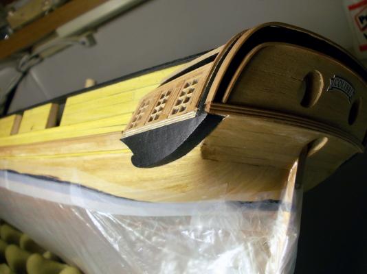
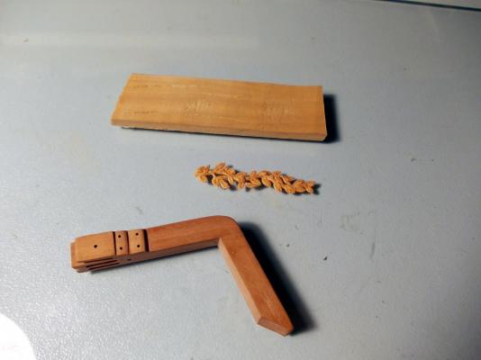
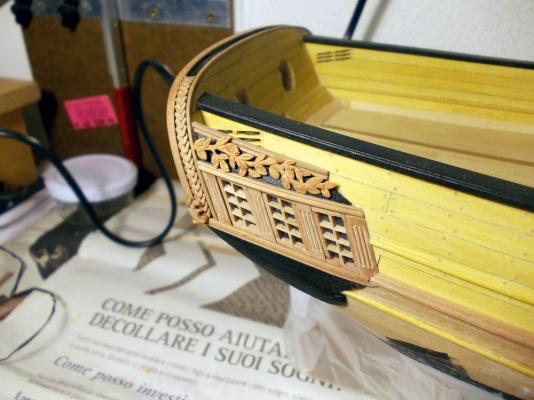
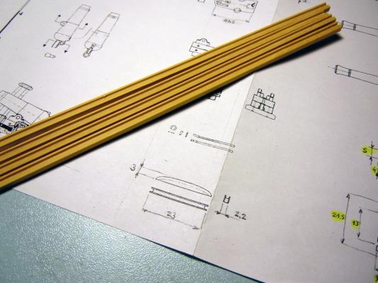
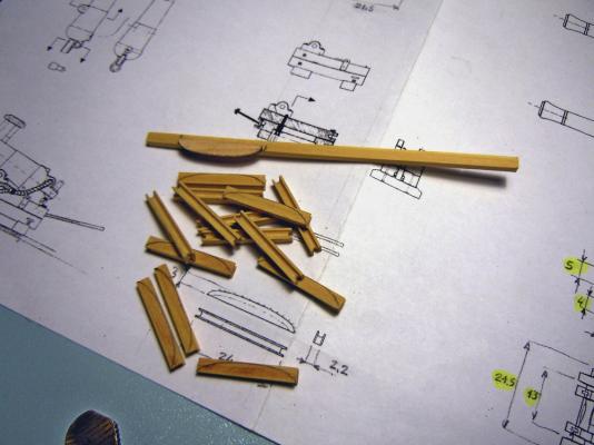
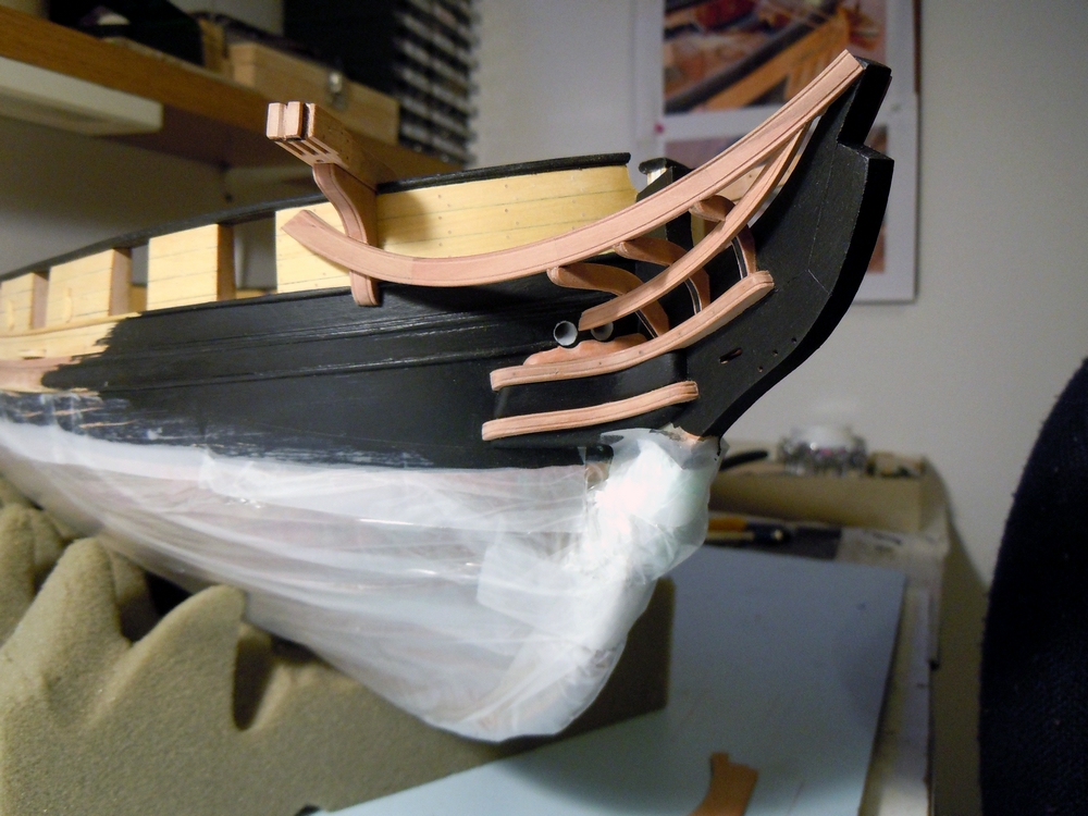
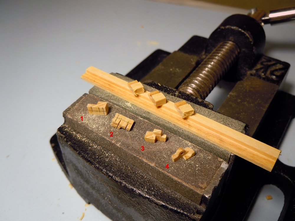
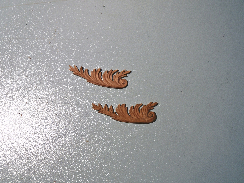
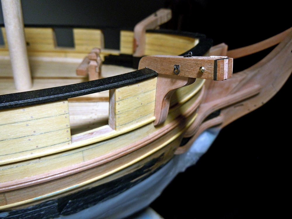
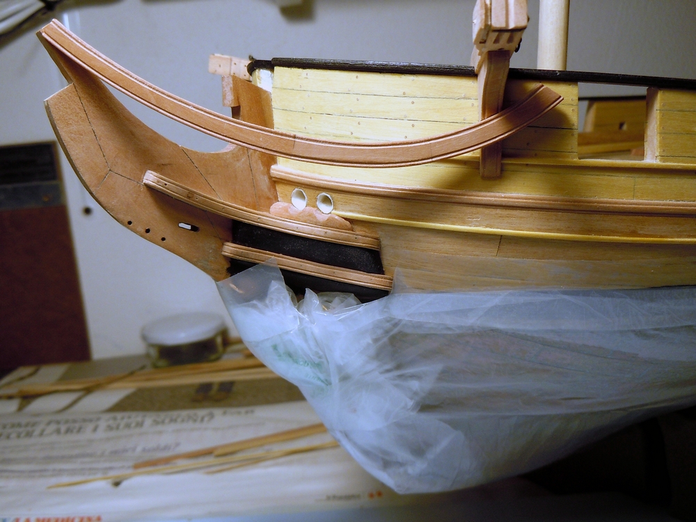
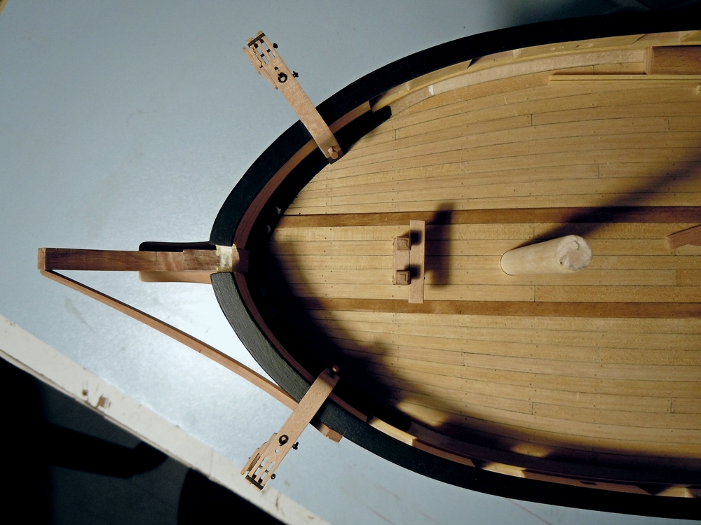
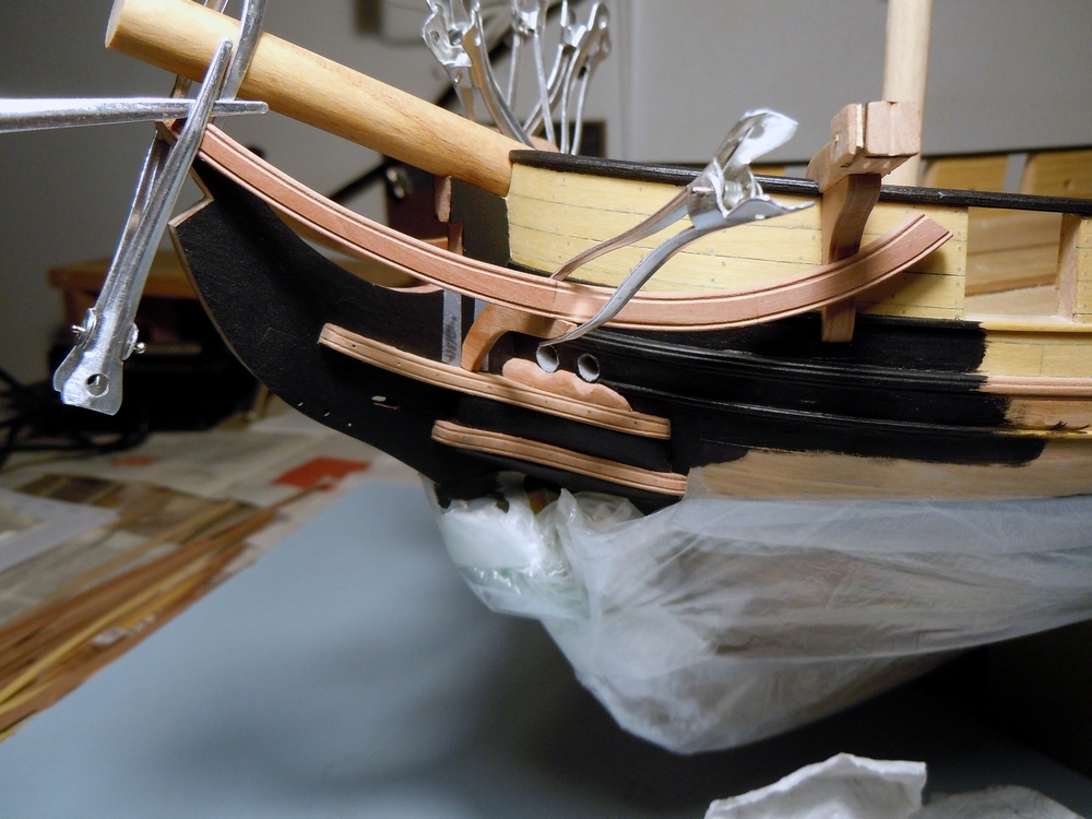
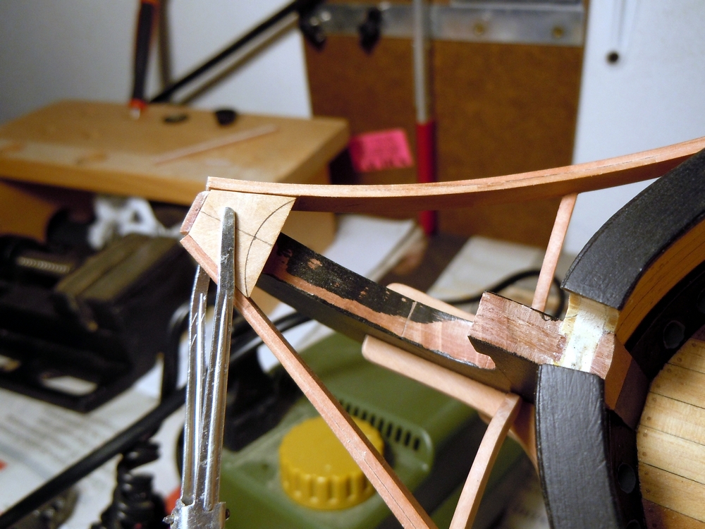
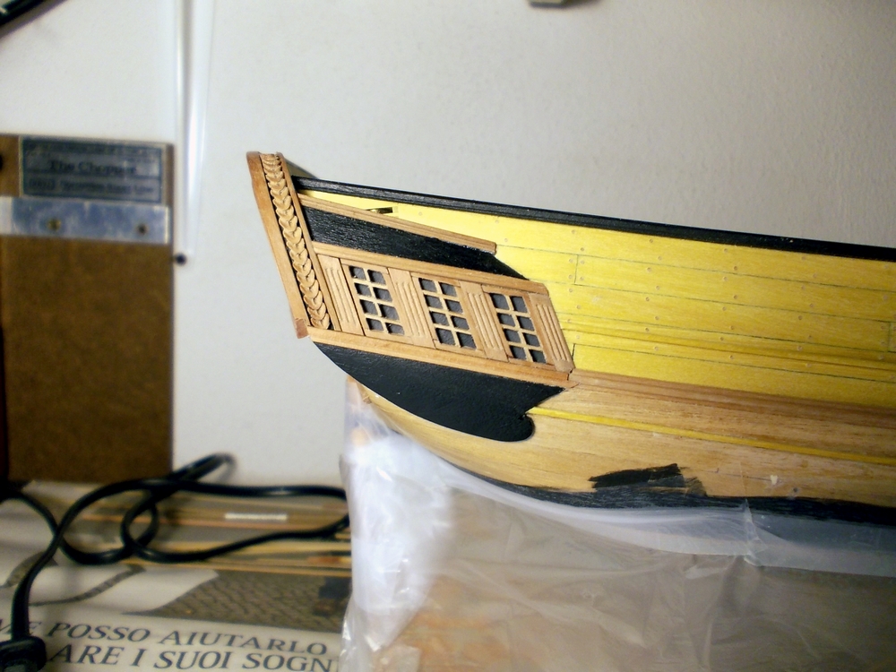
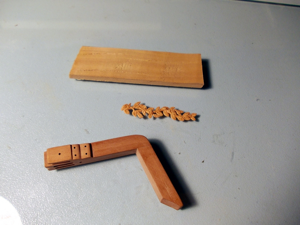
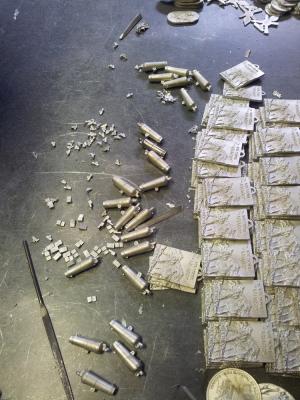
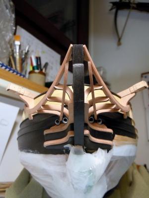
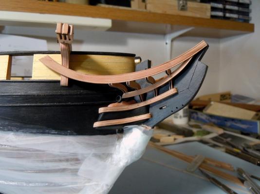
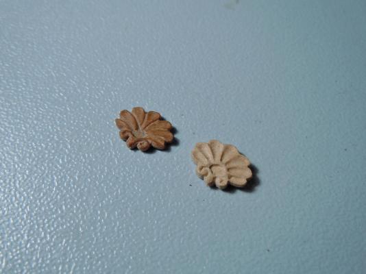
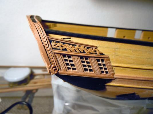
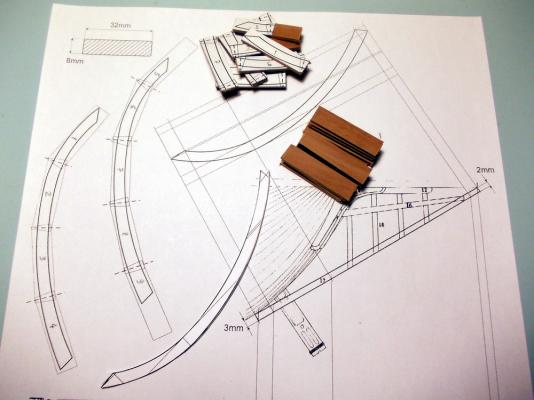
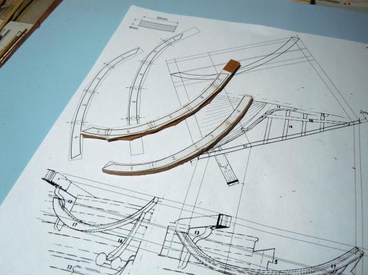
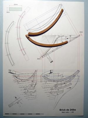
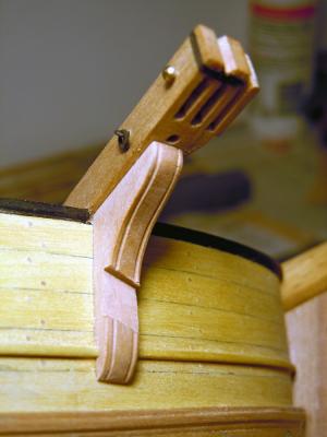
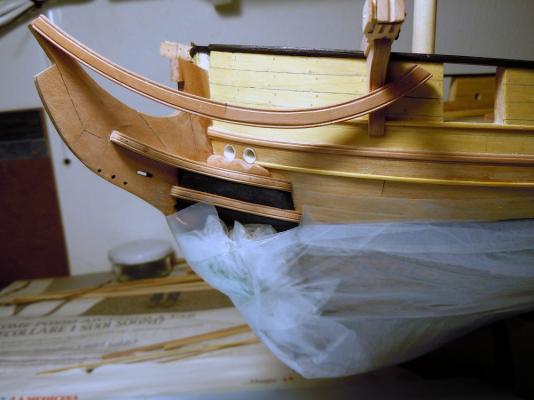
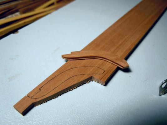
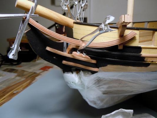
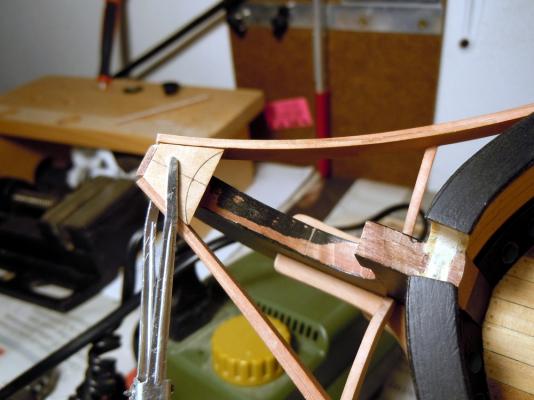
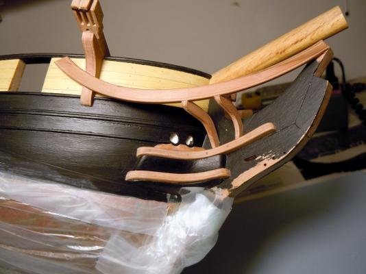
March 16th, 2016 Hi all a new update from the dockyard of the French brig “Colibri”. It has been a busy period, with many tasks started at the same time to interrupt the challenging carving activity...that I absolutely hate!! First task: Continuing preparation of carronades parts masters for pewter casting. While my friend was still lathing the second carronade barrel, I have prepared the barrel supports masters: they are built with hard Yellowheart wood as I’ve been assured that the curing temperature of the silicon resin to be used for the mold will not destroy them. In contrary case, they will be re-carved in lead alloy before creating the mold. The numbered sequence is self-explaining: I started from a milled batten and the pieces are singularly created by hand with a scroll saw, files and dental burrs loaded into my Proxxon rotary tool. They are 3 LH side parts and 3 symmetrical RH side parts. The measures of the completed pieces are 3x4x7 mm. Next task: Completing the carved stern decorations. The first picture shows a palm-tree leaf to be installed on the center-top of the transom. I carved it erroneously with light color Pearwood, with bas-relief method, and the re-carved from darker Pearwood using the high-relief method. The size is 8,5x5x1 mm. The following were the leaves decorations for the roofs of the stern (fake) side-galleries. For this very delicate and thin detail I used the FIMO© as previously described, and the following are the resuts: The color shade, slightly yellowish, is not exactly the same as for the other wood decorations but I think it is acceptable. Also better visible are the small Acanthus leaves carvings at the corner of the gallery and transom moldings. And finally a shot of the almost completed stern decorations: Still missing are the decorations for the parts below the galleries windows (I don’t know the name for this). I wanted to try again with the FIMO©, so drew a curl with a fan of Acanthus leaves curved upward and rearward and tried to reproduce it with this material. The result was not completely satisfactory, because after cooking in the oven the material still remains a bit soft (a bit harder than a pen eraser, but still too soft) and I could not get an acceptable smooth finish. So decided to try again with wood carving: below is shown the results comparison (consider that total thickness of the carved Pearwood is 1mm in the thicker areas). Obviously my final choice was for wood, and the following picture shows the completed stern-galleries. Next task: Completing the catheads. As described earlier, I rebuilt them from a single piece of Cherywood, ‘L’ shaped and beveled to match the bulwark internal surface and the waterway and to protrude outboard with an angle slightly more than 90 degrees (toward poop) w.r.t. the bulwark itself. Then cut two slots for the anchor tackle pulleys, and added a cleat on the forward side of the beam to house a third pulley, whose scope is still a mystery to me. I’ve ordered several 5mm diameter brass pulleys from RB-Model-Fittings at The Model Dockyard on-line shop. A knee is supporting the cathead outboard, and then the last details can be then added: a ‘V’ shaped groove on the horizontal beam head, an iron band, two ring-bolts and an internal cleat. I added a filling piece of scrap wood in lieu of the third pulley, hold in position by a brass nail, to protect the thin cleat wall from possible breakage. Next task: Building the bow rails joining the catheads to the knee-of-the-head. There are two rails whose shapes can be deduce from the Ancre plans with several geometric projections. I started with the main one: decided to build it in two layers of multiple pieces, in order to keep the wood grain as much as possible along the curved arch direction. The pieces are staggered by half their length, using the sketches shown here below. Here are the two rails’ pieces assembled, with the rail ready for finishing: the upper in the picture is the LH side rail, showing its internal side And here are the two rails completed, with two scraped grooves as decorations on the outboard face. Another carved decoration is scheduled on the aft end and will be built later. The small block piece on the inside end of the lower rail is intended to fix this end against the bulwark. The drawing on the background explains the projection method I used to find the correct shape of the rails from the 3-view plans. To install the rails, a cut-out must be created in the cathead's knee face. The following pictures show the modified knee and the port rail temporarily fit for installation checks. The rails are supported from below by a series of four head-timbers that lay above the cheeks and against the head-of-the-knee. The rough shape of these pieces is included in the plans, but they must be adapted with lot of dry-fit tests and modification to get the correct shape. A squared 'U' groove is scraped in the external face and my intention is to paint matt-black the bottom of this groove. The bolsters are also visible after their definitive installation. Quoting and in total agreement with Dan Vadas's buildlog "...Their function is to prevent the Hawse Cable from chafing on the upper cheek and planking around the holes.... Making one of these was enough of a mission - it took me 3,5 hours to shape..." The bow has been partially painted with a first coat of black, to avoid the need of reaching hidden areas after all the headwork is completed. The next picture shows the first head-timbers couple definitely fitted and the building of the trapeze piece joining the two main rails to the tip of the head-of-the-knee. I used the detailed step-by-step description posted by Dan Vadas for his HMS Vulture as a tutorial, but decided to reverse the sequence by installing firstly the head-timbers and then the beams joining the rails in athwart direction. This will be shown in a next post. The last picture of today shows the second couple of head-timbers installed below the rails. That’s all for today. Cheers FAM


-
Shaz sorry but I forgot a small but significant detail: French and British/US navies had different techniques to lay the copper tiles rows ... be careful to use the correct one! Bye Fam
-
Thank you all for the many likes and kind words! Carl, I know my limits and try to overcome them as I can ... I'm quite open-minded on tricks, provided I get the result I want Fam
-
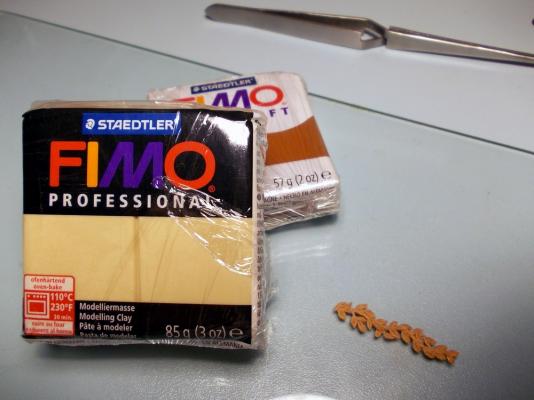
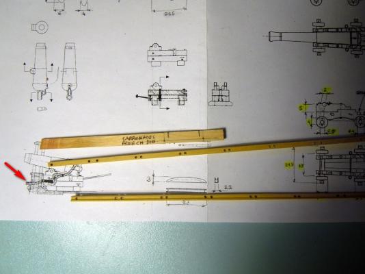
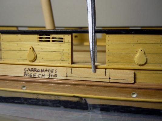
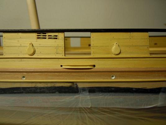
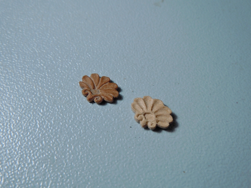
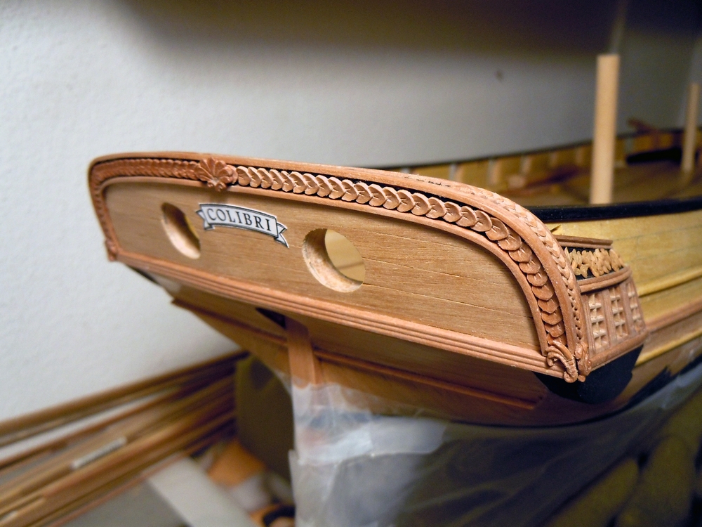
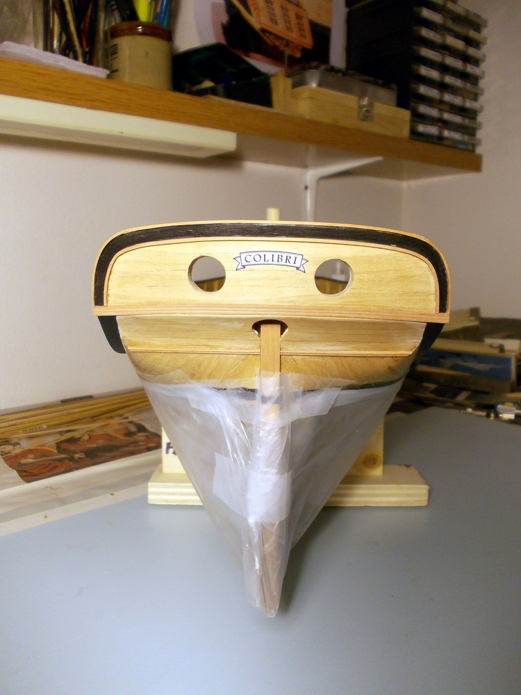
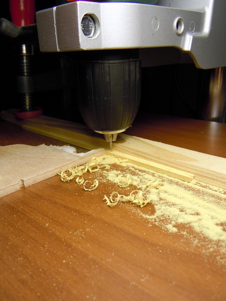
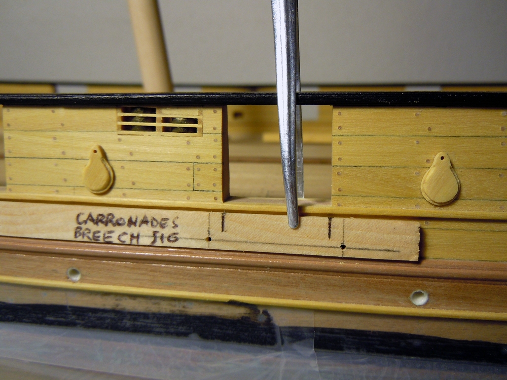
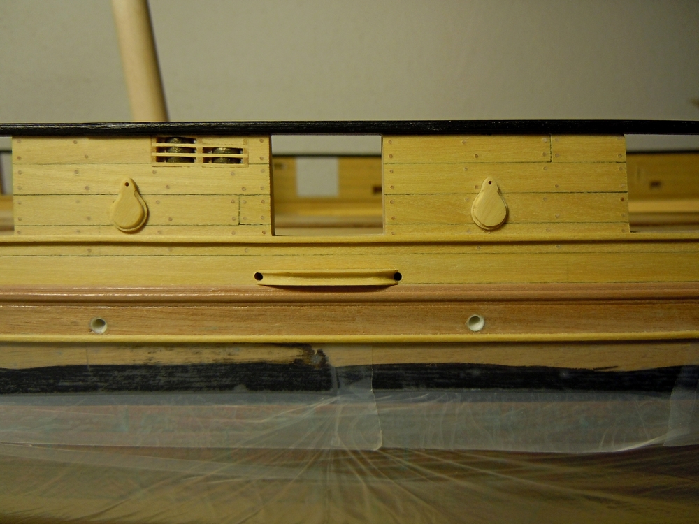
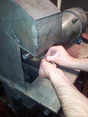
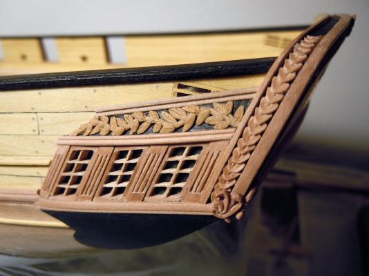
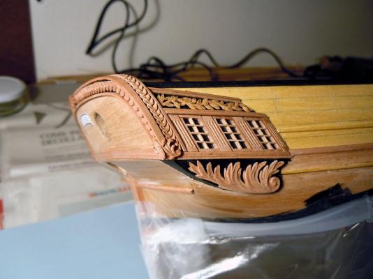
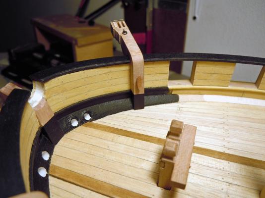
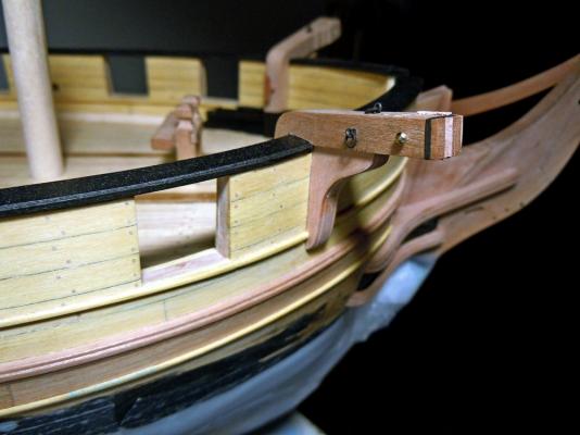
February 23rd, 2016 Hi all as I’m working on multiple items, I’ll post several small updates in the next weeks. Firstly I’d like to show the pieces that complete the stern galleries in their bottom part: they were carved from solid blocks of Basswood, using a technique similar to the cheeks for matching the curved surface of the hull. Of course I started from the flat upper surface, then slowly carved the internal surface until getting a good fit with the curved hull. With these two joints completed, I traced the lateral and vertical profiles of the piece (as seen from above and from the side) and cut them with the scroll saw. Then I had to find a good match with the counter, adapting a little bit the shape of the back face so that the counter is flush with it. Finally I could carve the external surface so that, when seen from behind the poop, it is a continuation of the transom profile (third picture). The above picture also shows a little molding added to the lower edge of the counter, where it joins the hull planking. Another molding covers, and completes, the structure (floor) below the fake windows. Its junction with the lower transom molding will be later covered by a small carving (see below). A little touch of personalization is the ribbon with the ship’s name, that I’ve scheduled to carve from dark Pearwood (as for all the transom decorations). Of course I’ve no historical reference at all about this detail, so decided for something sufficiently simple and not intrusive but at the same time clearly identifying the ship. Speaking of decorations ... I was inspired by Ed Tosti buildlog of the Young America clipper, where he describes the stern friezes ... so decided to give it a try when I saw some FIMO© packages in a fine arts store. I chose two colors because wanted to try obtaining a tone as much similar as possible to the shade of Pearwood I’m using for the stern decorations. To the right of the FIMO© is a test decoration (branch with leaves) that I obtained with 8 parts of light-tan color and two parts of cherry color ... here below is how the 8:2 mix is matching the two shades of Pearwood I’m currently using (the lower is the discarded cathead piece) ... ... and here is how the same sample looks like on the starboard galleries: After sculpting the sample on a flat pane of glass, I cooked it (still on the glass) for 30 minutes in the kitchen oven pre-heated at 110°C: no change in color to report, but the material is still a bit flexible. This is ok for me, considering that the decoration will be applied to curved surfaces. I’ve to admit I’m quite surprised by how easily I got it and pleased by the result. Next will be to mold the floral decorations for the upper and lower pieces of the galleries, because that little carving you can see at the rear-lower corner of the galleries (above picture, at the junction between two moldings I mentioned above) took three hours of total concentration and sweet and stress... I cannot really imagine carving all the remaining decorations! My total admiration and respect for those who have this skill, but it is not my job ... definitely! Jumping to another matter: there are several little details on the exterior of the bulwarks that I’m keeping to relax from the stress of carving : - the oar ports shutters - the rails for the carronades breeching ropes - the external ladder steps The shutters have no history: they are those simple flat pieces, with rain-drop shape, that I’ve already showed when I was deciding which shape to use for the oar ports. I just copied and pasted their paper drawings on a 8mm strip of Yellowheart wood, 1.5mm thick, then cut them out with the scroll-saw, sanded, hand-milled the step in their edge and glued to the hull. The brass pivot nail will come later. They are visible in the latter pictures of today’s post. Two out of seven on each side are left opened, so the oar port shape is partially visible; the others are closed. About the breeching ropes rails, they are basically 2.2x3mm battens with a U channel milled in the narrower side. I’ll show their scope in a while... The problem with these pieces is that I don’t own a mill, even if that beautiful Proxxon MF70 machine has been in my wish list for so long time that I’m starting to think I will never give this present to myself! So I had to try a setup of my column drill to make it work as a mill, using a 1mm diameter spherical mill bitt. I spent an entire Saturday afternoon trying to get a good and stable setup, with no result (well, I don’t consider 6 milled pieces thrown in the trash bin as a usable result!). The following Sunday I tried again with a different setup, and finally succeeded! The following picture shows my less than amateurial setup while milling one Yellowheart strip, the next picture shows the completed job. This is how this detail works: the carronade breeching rope of Le Cygne is not attached with hooks, or ringbolts, to the inside of the bulwark. It is made by a continuous rope loop, which starts inboard on one side of the carronade, passes outboard through a hole in the bulwark, around the external rail, back inboard through another bulwark hole on the opposite side, around the carronade, through the breech rope ring in the back of the barrel and then back to the starting point where it is fastened with a double seizing (see red arrow in the next shot). The external rail piece is obtained, after the U channel is milled, by drilling two holes in the channel at 23mm distance and then cutting the batten at the far side of these holes. Then the rail profile is drawn on the batten wider side and the rounded shape is sanded with the disk sander. The rail is glued to the bulwark, below the gunport sills, after having drilled the two pass-through holes in the bulwark itself (drilling jig in the next picture). Well ... only partially drilled, because these holes are sloping upward to exit above the waterway, so their remaining portion will be drilled from inside to outside. Final look of the rail (also the oar-ports shutters are visible): This is just the first test piece; the next 13 will come in the following days. Nothing to say about the ladder steps, will be done in the next days. Stay tuned... Cheers Fam