


Beef Wellington
-
Posts
2,249 -
Joined
-
Last visited
Reputation Activity
-

 Beef Wellington reacted to robdurant in HMS Ethalion 1797 by robdurant - FINISHED - Caldercraft - 1:64 - Modified from HMS Diana 1794 kit
Hi all,
Well, it's been almost two months since I posted, so here's a little post to show I haven't given up on Ethalion or simply disappeared. That said, I haven't been posting all the time firstly because I haven't got a huge amount done, and secondly because what I've done is a little on the repetitive side... But, here are a few pictures of progress. I've finished the futtock shrouds on the masts, and moved on to rigging the topmast shrouds and ratlines.
I have a workspace that wraps round the wall, and I've found this invaluable with all the turning round of the model - this is not a ship that can be built in a tiny space! And that's without the boom on the mizzen!
Thanks as always for the likes and encouragement, and I hope you're having a blessed advent-time!
Rob
-
 Beef Wellington got a reaction from Sjors in HM Brig-Sloop Flirt 1782 by Sjors - FINISHED - Vanguard Models - Scale 1:64
And another one completed! Well done, she's looking very nice Sjors. You really are the most prolific of builders, think you manage to complete more ships than most people manage log updates! Seriously, something again to be proud of, a beautiful model!
-
Beef Wellington reacted to Sjors in HM Brig-Sloop Flirt 1782 by Sjors - FINISHED - Vanguard Models - Scale 1:64
Last update.
She is finished!
It was a fun build and I enjoy it every minute.
Time to do some rigging at another model 🙂
The last picture is her final place where she is gonna stay.
Sjors
-
Beef Wellington reacted to Sjors in HM Brig-Sloop Flirt 1782 by Sjors - FINISHED - Vanguard Models - Scale 1:64
Wow, two updates after each other 🙂
The yards are is place and now the running rigging.....
Sjors
-
Beef Wellington reacted to Sjors in HM Brig-Sloop Flirt 1782 by Sjors - FINISHED - Vanguard Models - Scale 1:64
On a sunny day another update.
The bowsprit is done with the rigging.
Also de Jib boom and Gaf.
It's small but funny.
I'm pleased how it all comes together.
Now it is time for make the yards ready....
There all ready painted so time for the blocks.
Till another update.
Enjoy your day and keep healthy!
Sjors
-
Beef Wellington reacted to Wahka_est in HMS Cruiser by Wahka_est - Caldercraft - 1:64
Some progress.
Foremost mast ratlines done.
Main mast shrouds done, off to ratlines.
Have to finish bowsprit at some point as a lot of rigging goes those. Instructions are not so clear to understand, hope to get my answers from Thunders build.
-
Beef Wellington reacted to Mike_H in HMS Snake by Mike_H - FINISHED - Caldercraft - 1:64
I'm happy with the planking. Could have done better in a few places, but sanding and a fairly modest mount of filler should fix that. Decided to plank the stern counter as the simplest way of closing up with the hull planking. It also means I can repair a flaw in the curvature of the counter. Apart from trimming the planks at the stern to get at the counter, and the counter itself, I've not sanded anything yet. I have not fully planked the false keel as an alternative to rebating the planks. I'll see how that goes. I soaked the planks and was surprised to see how much they swelled, and then shrank on drying.
Thinking that I might pin the second planking (Horror!) as it will all be painted or be beneath the copper - would welcome views on that.
-
Beef Wellington reacted to drtrap in HMS Snake by drtrap - FINISHED - Caldercraft
Hi guys, I'm still here after so many days.
Trying now to start and establish the right steps to attach the lower yard of the fore mast.
A couple of pics trying to set according to Petterson the slin of that yard.
Thank you
-
Beef Wellington reacted to drtrap in HMS Snake by drtrap - FINISHED - Caldercraft
Next step is to maintain the right proportion for the sling and the relative attachments
-
 Beef Wellington got a reaction from ccoyle in HMS Snake by Beef Wellington - FINISHED - Caldercraft - Scale 1: 64 - First wooden ship build
Cheers everyone, grateful for the continued interest to keep some wind in the sails...
@Kevin - I think you and I have similar workstyles, the difference though is that you get a lot more done!
Rigging Update...
As previously mentioned, rigging just does not lend itself to updates as there always seems to be just one more job to complete before an update would be appropriate. Pretty much all rigging in the main and mizzen mast areas is complete. This definitely required some planning ahead to ensure room to work. The main topgallant braces were the last added as the place seriously limits access in an already tight space. Also redid a few completed rigging items in the bowsprit that have been bothering me, but before starting rigging in earnest, I felt the old girl needed a fairlead saddle. After trying, unsuccessfully to make something out of wood, I found that gluing a couple of styrene strips together and then bending around a dowel while steaming kept the styrene with the right curve. The profile could then be better approximated and the hole drilled...far from perfect but looks OK to the unaided eye (the paint was used at this point only to get some contrast on the surface). One item that continues to annoy me is the application of a single 'bee' as per the plans. I can find no other example of this and it just doesn't seem correct, and means that a fore topmast preventer stay cannot be rigged, but sadly that is just not fixable at this point...
Bowsprit rigging:
The bowsprit rigging shown on the plans has to be the least clear of any on this model, and it seems to have been significantly simplified to the point of non-utility/confusion in a couple of cases. I've decided to follow Lever and Lees (an excellent reference!) and leverage Petersson. Any mistakes in interpretation and execution are of course my own...
I also felt that Snake deserves a 'traveller' (the jib stay being completely omitted from the plans) which needed to be installed before the jib boom horses. This was made from a single brass wire ring, a spare PE rigging hook, and mutilated PE swivel mount. This was my first attempt at soldering, which let me know in no uncertain terms that I have much to learn! The hook is a little big, but looks acceptable to my eye once fully installed.
Moving on to the various rigging elements...
Spritsail sling: The sling was made of a served line and fitted according to Lever and Lees - essentially the same as for the yard slings. Spritsail stirrups and horses: These were all fitted in situ once the spritsail yard was installed to ensure the stirrups hung vertically Jib Boom Horses: (Lees P51) Secured to eyes in the bowsprit cap, and lashed around the end of the jib boom Inner/Outer Martingales: There does not seem to be single definitive reference to help, and it seemed necessary to piece together info from a variety of sources. Lees indicates the late 18th/early 19th century was period of rapid changes in dolphin striker/bowsprit rigging over a pretty condensed 20yr period. I decided to rig 2 martingales. The inner martingale was seized around the traveler, and the outer martingale seized around the jib boom end. Both were taken through blocks lashed to opposite sides of the bowsprit to lead them over the spritsail yard, and secured using a gun tackle setup to a timberhead. Jib Stay: (Petersson P19) A block was added to the fore topgallant mast to carry the jib stay, one end lashed to the traveler and the other secured via a tackle to inboard starboard pin rail. Fore Topgallant Stay: (Petersson P61) Led through an eye seized to the bowsprit end and secured to the stay using thimbles, a collar and a lashing which was frapped. Jib Outhaul: (Petersson P21 & P62) One end seized to the traveller, led through a sheave cut into the bowsprit to a tackle. Petersson indicates use of a violin block, Lever suggest use of both a violin and a double block system. For a bit of variety (and because I’ve become increasingly unhappy with the look of the supplied items), a double block system was used and this was secured to a timberhead. Jib Boom Guys: Seized around jib boom end and secured using a gun tackle to a cleat on the capping rail Spritsail Yard Halliard: (Petersson P59) Secured to a timberhead per Petersson, rather than pin rail as called out on the plans. Spritsail Braces: (Petersson P47) Plans are reasonably Spritsail lifts: (Lever Ch40, Petersson P64 and plans) Secured to timberhead per Petersson, rather than pin rail as called out on the plans. Bowsprit horses and netting: (Petersson P91, Lees 84) The location of the eyebolts seems to be shown both on the front face and top of the timberheads, and settled on the top mounted option. These were simplified a little to and simply seized to the eyes rather than using an eye and lashing. The bowsprit netting was made from two brass wire pieces fed through the line, which were secured with some fine thread. This was then suspended using a couple of clamps on the keel former offcut from "Jason", which allowed the ropes to be secured and wrapped around the wire. Each turn was secured before moving onto the next. It helped having this under slight tension throughout.
The following show how everything ended up....
And finally...the overall state of where things stand:
-
 Beef Wellington got a reaction from drtrap in HMS Snake by Beef Wellington - FINISHED - Caldercraft - Scale 1: 64 - First wooden ship build
Hi Folks, have been away from the shipyard and this site for quite some time, and I've missed the friendly interaction. Looking forward to catching up with everyone's builds soon!
@Martin - welcome to the neighborhood! We got lucky and didn't lose power in the storms, hope you stayed safe. We definitely need to connect at some point so I can pick your brains 🙂
@ Sjors - Good to hear from you old friend, its been a while! Will check out your new model soon.
@ Stergios - the yards were rigged from bottom to top. Not sure if that is the recommended way, but it made sense to me to do that way because the lower masts require quite a few items of rigging to be in place near the mast and it seemed that this would be harder if the lines from the top masts were getting in the way. Maybe personal preference?
The cutter has finally been finished and the details of the final stages of construction are posted in my 'Jason' build log. Figuring out where to place the cutter onboard Snake was a little bit of a challenge. It seems inconceivable that a ship (sloop) like Snake would not have at least one boat, but there is simply no space to place one. I could find no examples of solutions to this in practice (recognizing that other ships may well have had raised davits), and it seems somewhat logical to mount the supports on the coamings which would also be supported by the deck beams underneath. Finally in position, its clear that even a modest 24' cutter has little room to spare.
With that done, now rigging can continue, hopefully some progress possible soon...
-
 Beef Wellington got a reaction from chris watton in HMS Snake by Beef Wellington - FINISHED - Caldercraft - Scale 1: 64 - First wooden ship build
@Mike - thanks for the kind words!
@Martin - I guess I'm located in the valley just over the hills from the Litchfield Hills of Connecticut 🙂
Rope Coils...
Before any more rigging can be completed, rope coils really need to be attended to. Once the remaining braces, cluelines and sheets go on, access will be impossibly restricted. I'm not a fan of gravity defying suspended circular coils which don't quite look right to my eye. I really wasn't quite sure of the approach to take, but I knew I wanted to try to replicate the shear mass of heaps of rope often shown on period photos and try to give the rope some mass, but knew that doing so would be very difficult using the kit rope.
After many attempts, a mock up of the pin rail was made up and the rope stretched around a belaying pin and some wire. Dilute PVA was then applied to ensure it kept its shape, and some extra rope wrapped around to keep the shape. Once trimmed and the glue has dried, these can be hung over the desired location. These still require some fettling and wanted to see how I feel about them in a few days with a number on position before securing or trying an alternative approach. I'd welcome thoughts and suggestions...
-
 Beef Wellington got a reaction from DaveBaxt in HMS Diana by Vane - Caldercraft - Scale 1:64
Glad to catch up on more progress on your Diana. Good decision to do the gun ports correctly, you'll be much happier I think. That last shot really shows off the great work on your deck - one of my struggles is finding more decent maple to do the upper decks.
-
 Beef Wellington got a reaction from Vane in HMBV Granado by Vane - Caldercraft - Scale 1:64
With the waterline in place , it really shows that you nailed the line of the wale. Very nice, you've got a beautiful foundation to build on.
-
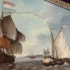
Beef Wellington reacted to Vegaskip in Ship paintings
The Skipper somewhere on the Thames late 19th Century 16.5” X 11.75”
-
Beef Wellington reacted to Vegaskip in Ship paintings
Hi guys, being retired I can paint more or less when I want (subject to domestic chore from 'she who must be obeyed). I normally paint for about 3 to 4 hrs in the afternoo, probably 2/3 times a week.
The Belfast pic started about 1.50pm, and I took the photo about 5pm, I'll probably have an other half hour fixing bits , the after funnel top is wrong, and horizon on the right needs lifting a bit. The longest painting I have done, was three afternoons and was a diptych of 'the Tail o' the Bank' on the river Clyde .
see pictures.
jim
-
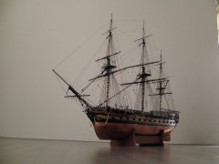
 Beef Wellington got a reaction from Jorge Diaz O in HMS Jason by Beef Wellington - Caldercraft - 1:64 - Artois-class frigate modified from HMS Diana 1794
Hi Folks,
Sadly been rather absent from both the shipyard and this site for some time. I very much hope to catch up soon on everyone else's fine builds here soon. Time to get a little more up to date, the cutter is pretty close to completion aside from a little fettling.
Frames were added to the interior using strips cut from some scrap 0.5mm pear wood. These were soaked and pre-bent in situ prior to gluing with PVA:
The frames were further reduced down to the keel former to try and get a bit more depth the boat. To my eye, applying planking to the false deck puts the board too high, especially as there is very little room to play with considering the various structural elements still to go on. A template for the footwaling was then made up to determine the shape. Once the placement was determined, the rising plank was added (again cut from some 0.5mm pear sheet)
I wanted to try and allow the footwalling to have an element of curvature which would be natural on the real boat. A relatively straightforward way to achieve this was to apply wood strip to thin card to match the template which maintains a lot of flexibility (Straight strip was used rather than the more complicated curved planking on the plan). Once dry, the assembly was easily glued on top of the keel former, the footwaling then follows the interior curve naturally.
With those element in place, it was possible to add the platform under the sternsheets. The Diana plans show these as a grating, but to my eye again the kit supplied grating is too large, so plain boards were installed instead which also appear to be used. After the main and fore mast steps, thwarts and ringbolts I assume would be used for hoisting the boat had been added, the bow was closed in using a cover as suggested on the plan - this also helped disguise the rudimentary construction at the bow. The rowlocks were cut, interestingly these are not symetrical between port and starboard, and one seems to sit rather awkwardly in the sternsheets.
The sternsheets were made up and installed, again having used a template to finalise shape, together with all the other details including mast thwarts, gunwale and knees.
The colour scheme follows a slightly simplified version of that shown below which seems suitably utilitarian. Looking at this, and comparing once the black was applied, suggests to me that I made a mistake in the tapering of the clinker planking. The black area covers both the wash strake and upper strake, and judging from these pictures it appears that these are of somewhat consistent in width, especially toward the stem. I had tapered these proportionally as well, hoping nobody else notices...
-
 Beef Wellington got a reaction from p.hoek in HMS Snake by Beef Wellington - FINISHED - Caldercraft - Scale 1: 64 - First wooden ship build
@Mike - thanks for the kind words!
@Martin - I guess I'm located in the valley just over the hills from the Litchfield Hills of Connecticut 🙂
Rope Coils...
Before any more rigging can be completed, rope coils really need to be attended to. Once the remaining braces, cluelines and sheets go on, access will be impossibly restricted. I'm not a fan of gravity defying suspended circular coils which don't quite look right to my eye. I really wasn't quite sure of the approach to take, but I knew I wanted to try to replicate the shear mass of heaps of rope often shown on period photos and try to give the rope some mass, but knew that doing so would be very difficult using the kit rope.
After many attempts, a mock up of the pin rail was made up and the rope stretched around a belaying pin and some wire. Dilute PVA was then applied to ensure it kept its shape, and some extra rope wrapped around to keep the shape. Once trimmed and the glue has dried, these can be hung over the desired location. These still require some fettling and wanted to see how I feel about them in a few days with a number on position before securing or trying an alternative approach. I'd welcome thoughts and suggestions...
-
 Beef Wellington got a reaction from md1400cs in HMS Snake by Beef Wellington - FINISHED - Caldercraft - Scale 1: 64 - First wooden ship build
@Mike - thanks for the kind words!
@Martin - I guess I'm located in the valley just over the hills from the Litchfield Hills of Connecticut 🙂
Rope Coils...
Before any more rigging can be completed, rope coils really need to be attended to. Once the remaining braces, cluelines and sheets go on, access will be impossibly restricted. I'm not a fan of gravity defying suspended circular coils which don't quite look right to my eye. I really wasn't quite sure of the approach to take, but I knew I wanted to try to replicate the shear mass of heaps of rope often shown on period photos and try to give the rope some mass, but knew that doing so would be very difficult using the kit rope.
After many attempts, a mock up of the pin rail was made up and the rope stretched around a belaying pin and some wire. Dilute PVA was then applied to ensure it kept its shape, and some extra rope wrapped around to keep the shape. Once trimmed and the glue has dried, these can be hung over the desired location. These still require some fettling and wanted to see how I feel about them in a few days with a number on position before securing or trying an alternative approach. I'd welcome thoughts and suggestions...
-
Beef Wellington reacted to Peterhudson in HMS DIANA by Peterhudson - Caldercraft - 1:64 Scale
Ahhh - tab on the keyboard activates send! A garbled partially complete message!
The routine:
a. I attach a deadeye to the line, seize and wash with dilute PVA - cut the line to an approximate length.
b. I hold the deadeye in position with the 15mm wire; and place a second deadeye on a wire spacer on to the adjacent deadeye. Loop the black line over the masthead and tension it around the second deadeye. Don't pull too hard as it easy to unlodge the lower deadeye.
c. A dab of CA is applied, just enough to hold the line in place whilst removing the wire spacer.
d. Seize the second deadeye and trim the shroud neatly.
e. Once the glue is dry, re-secure the deadeyes with the wire spacers and tie off the shroud at the masthead. This creates the tension in the shroud.
f. Insert the lanyards and tie off.
Looks okay.
-
Beef Wellington reacted to Peterhudson in HMS DIANA by Peterhudson - Caldercraft - 1:64 Scale
With the various sections of the mast complete and a number of blocks fitted, I have moved onto the shrouds. I haven't made a model this large before so it has been a bit of an adventure, however, once I settled my routine, they were comparatively straight forward. I cross checked the various details with a book called 'Rigging Period Ship Models' by Lennarth Peterson which I picked up in a second hand book shop; it shows in really straight forward diagrams all the various configurations of the masts, spars, standing and working rigging and is a good complement to the kit plans.
Blocks were attached to the 1.25 and 1mm lines in the normal way; treble seizing and then, having correctly aligned the block, washed with dilute PVA. I attached the Burton pennants - straightforward.
I then began assembling. I started with the mizzen as the kit supplied was missing the 1.25mm line which I had to reorder. Forward starboard first, then alternate with the port shrouds. I followed this routine:
a.I used the wire spacers to hold the blocks in place and to get the correct shroud length, and thus tension, I looped the
whilst I tensioned the line and tied it off at the mast head
-
Beef Wellington reacted to Barbossa in French Frigate by Barbossa - 1/64 - POB based on La Vénus (ANCRE) - semi-scratch
You're welcome, Jason.
The colors are a bit of a lucky shot.
Applying some coats of (water-)dilluted PVA-glue made painting of the windowframes redundant.
The arch above the windows = same story. This is a decorative thread which I firmed up with cyano glue and guess what's happened ? A nice looking brown which was pretty close to a warm (woodish) color.
Talking about woodish effect : for painting purposes I often use AV New Wood 311.
For the pillars, the Artesiana Latina scrapping tool is an object of necessity.
The grey paper behind the windows was the only option left because obtaining a real window effect was far beyond my skills.
Regarding to the latter I'm giving it some thought using the same technique for the sternlamp.
-
Beef Wellington reacted to mtaylor in French Frigate by Barbossa - 1/64 - POB based on La Vénus (ANCRE) - semi-scratch
Your stern looks fantastic, Christian.
-
Beef Wellington got a reaction from drtrap in HMS Snake by Beef Wellington - FINISHED - Caldercraft - Scale 1: 64 - First wooden ship build
@Mike - thanks for the kind words!
@Martin - I guess I'm located in the valley just over the hills from the Litchfield Hills of Connecticut 🙂
Rope Coils...
Before any more rigging can be completed, rope coils really need to be attended to. Once the remaining braces, cluelines and sheets go on, access will be impossibly restricted. I'm not a fan of gravity defying suspended circular coils which don't quite look right to my eye. I really wasn't quite sure of the approach to take, but I knew I wanted to try to replicate the shear mass of heaps of rope often shown on period photos and try to give the rope some mass, but knew that doing so would be very difficult using the kit rope.
After many attempts, a mock up of the pin rail was made up and the rope stretched around a belaying pin and some wire. Dilute PVA was then applied to ensure it kept its shape, and some extra rope wrapped around to keep the shape. Once trimmed and the glue has dried, these can be hung over the desired location. These still require some fettling and wanted to see how I feel about them in a few days with a number on position before securing or trying an alternative approach. I'd welcome thoughts and suggestions...
-
Beef Wellington got a reaction from drtrap in HMS Snake by Beef Wellington - FINISHED - Caldercraft - Scale 1: 64 - First wooden ship build
Cheers everyone, grateful for the continued interest to keep some wind in the sails...
@Kevin - I think you and I have similar workstyles, the difference though is that you get a lot more done!
Rigging Update...
As previously mentioned, rigging just does not lend itself to updates as there always seems to be just one more job to complete before an update would be appropriate. Pretty much all rigging in the main and mizzen mast areas is complete. This definitely required some planning ahead to ensure room to work. The main topgallant braces were the last added as the place seriously limits access in an already tight space. Also redid a few completed rigging items in the bowsprit that have been bothering me, but before starting rigging in earnest, I felt the old girl needed a fairlead saddle. After trying, unsuccessfully to make something out of wood, I found that gluing a couple of styrene strips together and then bending around a dowel while steaming kept the styrene with the right curve. The profile could then be better approximated and the hole drilled...far from perfect but looks OK to the unaided eye (the paint was used at this point only to get some contrast on the surface). One item that continues to annoy me is the application of a single 'bee' as per the plans. I can find no other example of this and it just doesn't seem correct, and means that a fore topmast preventer stay cannot be rigged, but sadly that is just not fixable at this point...
Bowsprit rigging:
The bowsprit rigging shown on the plans has to be the least clear of any on this model, and it seems to have been significantly simplified to the point of non-utility/confusion in a couple of cases. I've decided to follow Lever and Lees (an excellent reference!) and leverage Petersson. Any mistakes in interpretation and execution are of course my own...
I also felt that Snake deserves a 'traveller' (the jib stay being completely omitted from the plans) which needed to be installed before the jib boom horses. This was made from a single brass wire ring, a spare PE rigging hook, and mutilated PE swivel mount. This was my first attempt at soldering, which let me know in no uncertain terms that I have much to learn! The hook is a little big, but looks acceptable to my eye once fully installed.
Moving on to the various rigging elements...
Spritsail sling: The sling was made of a served line and fitted according to Lever and Lees - essentially the same as for the yard slings. Spritsail stirrups and horses: These were all fitted in situ once the spritsail yard was installed to ensure the stirrups hung vertically Jib Boom Horses: (Lees P51) Secured to eyes in the bowsprit cap, and lashed around the end of the jib boom Inner/Outer Martingales: There does not seem to be single definitive reference to help, and it seemed necessary to piece together info from a variety of sources. Lees indicates the late 18th/early 19th century was period of rapid changes in dolphin striker/bowsprit rigging over a pretty condensed 20yr period. I decided to rig 2 martingales. The inner martingale was seized around the traveler, and the outer martingale seized around the jib boom end. Both were taken through blocks lashed to opposite sides of the bowsprit to lead them over the spritsail yard, and secured using a gun tackle setup to a timberhead. Jib Stay: (Petersson P19) A block was added to the fore topgallant mast to carry the jib stay, one end lashed to the traveler and the other secured via a tackle to inboard starboard pin rail. Fore Topgallant Stay: (Petersson P61) Led through an eye seized to the bowsprit end and secured to the stay using thimbles, a collar and a lashing which was frapped. Jib Outhaul: (Petersson P21 & P62) One end seized to the traveller, led through a sheave cut into the bowsprit to a tackle. Petersson indicates use of a violin block, Lever suggest use of both a violin and a double block system. For a bit of variety (and because I’ve become increasingly unhappy with the look of the supplied items), a double block system was used and this was secured to a timberhead. Jib Boom Guys: Seized around jib boom end and secured using a gun tackle to a cleat on the capping rail Spritsail Yard Halliard: (Petersson P59) Secured to a timberhead per Petersson, rather than pin rail as called out on the plans. Spritsail Braces: (Petersson P47) Plans are reasonably Spritsail lifts: (Lever Ch40, Petersson P64 and plans) Secured to timberhead per Petersson, rather than pin rail as called out on the plans. Bowsprit horses and netting: (Petersson P91, Lees 84) The location of the eyebolts seems to be shown both on the front face and top of the timberheads, and settled on the top mounted option. These were simplified a little to and simply seized to the eyes rather than using an eye and lashing. The bowsprit netting was made from two brass wire pieces fed through the line, which were secured with some fine thread. This was then suspended using a couple of clamps on the keel former offcut from "Jason", which allowed the ropes to be secured and wrapped around the wire. Each turn was secured before moving onto the next. It helped having this under slight tension throughout.
The following show how everything ended up....
And finally...the overall state of where things stand: