HOLIDAY DONATION DRIVE - SUPPORT MSW - DO YOUR PART TO KEEP THIS GREAT FORUM GOING! (Only 24 donations so far out of 49,000 members - C'mon guys!)
×
Maury S
-
Posts
1,490 -
Joined
-
Last visited
Content Type
Profiles
Forums
Gallery
Events
Everything posted by Maury S
-
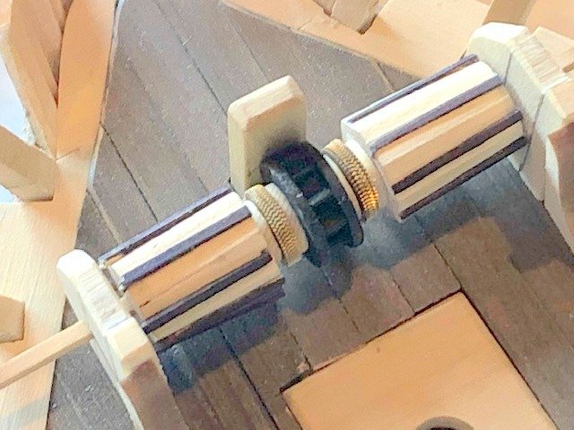
 I turned some windlass barrels. They are correct scale to the plans. Whelps will be tough. Maury Maury
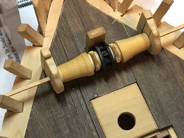
-
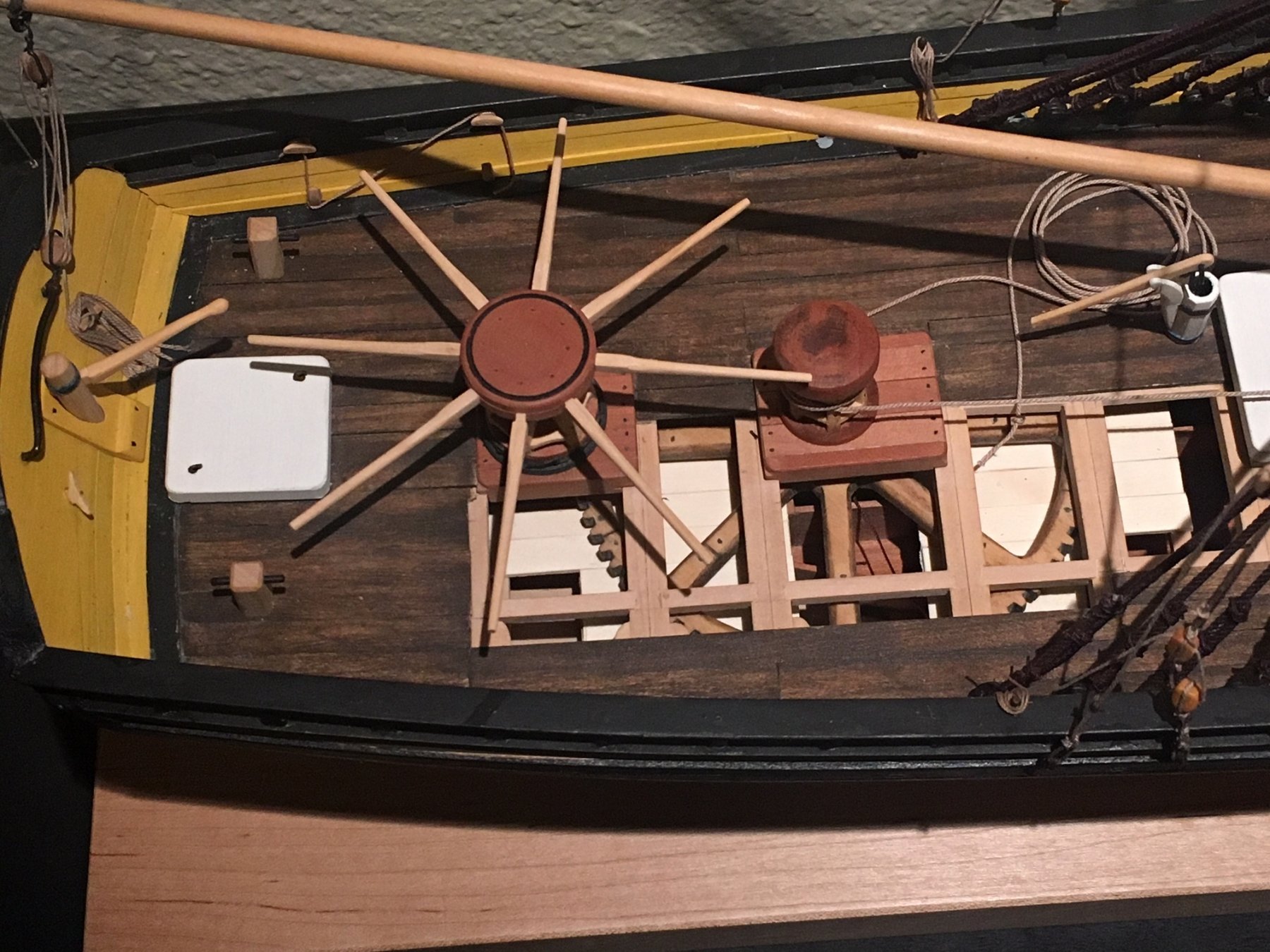
I spent a day "kit bashing" Syren Ship Model's Windlass kit. It came out OK but the scale is too large for this boat. Boats of 85 - 105' had windlasses of 18 - 24" max. diameter. The original plans show a max diameter of about 15". These come out somewhere above 20" and there is no room to maneuver around it on deck. I'm using some stacked watch gears for the purchase rim. The barrels are bashed from the kit and the construction system is great. I'm not a fan of AYC since it doesn't sand as well as box. The real windlasses of the era were built from a solid log so I'll try that for the barrels. This boat was built in 1846, right about the time that the pump-brake windlass was developed and it's not clear from Chapelle's plan that this was of the pump-brake type. Maury
-
Regarding raising and lowering the centerboard...There are a couple of methods. 1] The board itself is usually weighted and will drop as much as allowed from this weight. There is a pendant attached to the mainmast with a guntackle arrangement to raise it. 2] Sometimes, instead of a chain or line, there was a 1" (+ / -) rod attached to the CB so downward pressure can be applied via the rod. At this stage, that's how this model is rigged. With a chain attachment, a pin was inserted in a link at the deck to prevent it from dropping too far. Maury
-
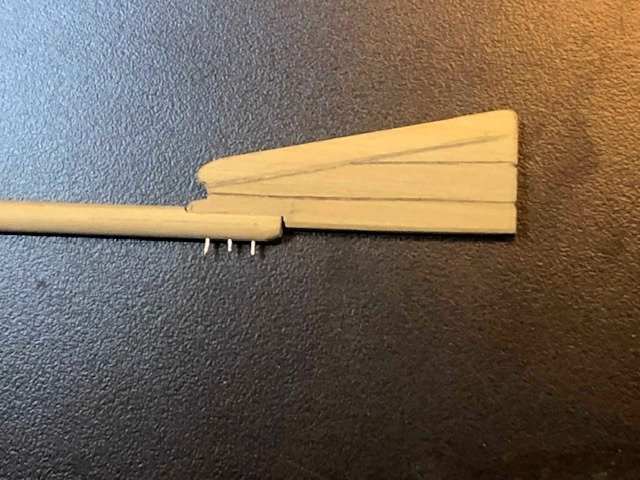
Lots of minor things being done. Here is the plug-stock rudder. It is round from its head down to the upper pintle. The key is the center of the round stock has to correspond to the fore side of the blade. The stock starts as a 4-sided piece, marked 7-10-7 and made 8-sided, then rounded with sandpaper. Before the rounding, I routed out a flat face on the aft edge of the stock and an off-setting notch on the fore side of the blade. They were then aligned on the mill and holes for the reinforcing bolts were drilled. The blade was assembled and tapered. Pins will be cut off flush before installation. As always, the pintles and gudgeons will be a challenge for me. Maury
-
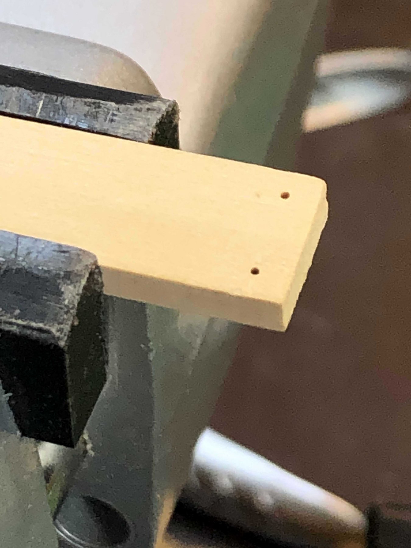
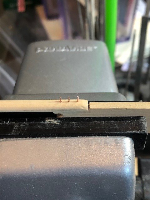
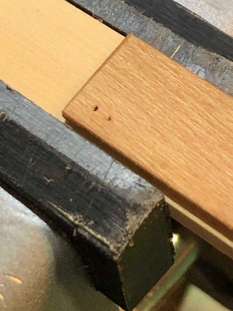
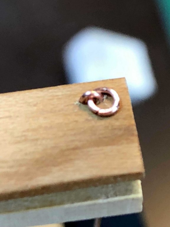
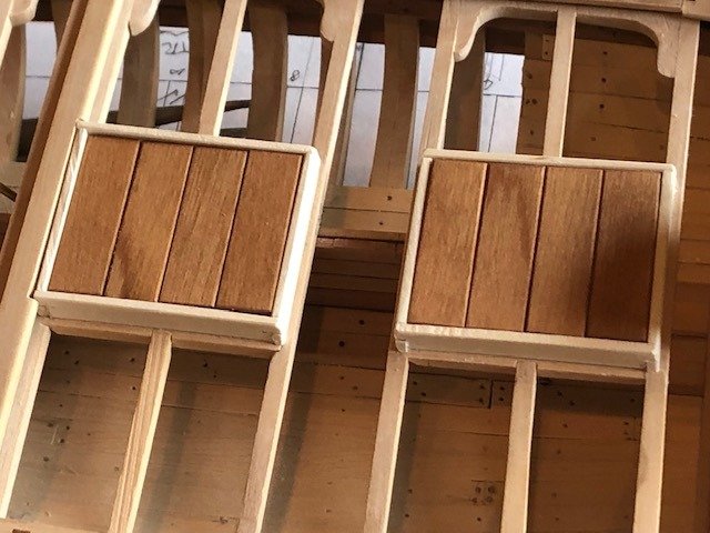
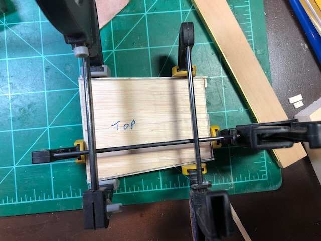
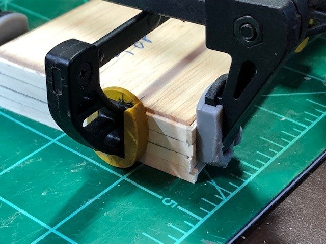
A little work on the hatch covers. They each have a staple and ring in opposing corners. This is a simple jig I use for holding the cover and staple. Just the same sized holes as the hatch cover, Rather than one hole for an eyebolt, I use two closely spaced holes for a staple (U-shaped wire.). The ring is held closer to the board rather than burying the heel of the eyebolt. The wire is hardened (stretched), wrapped around a 1/16" drill bit (3" internal dia. at scale) the cut off, pieces flattened a bit and squeezed together. they will be blackened later in a batch with other metal work. \ Another advantage is I only have to solder the rings, not an eye. Maury

-
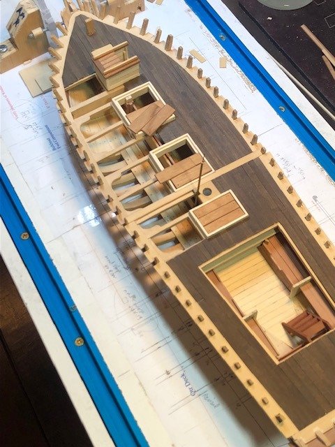
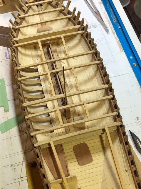
The planking is done. Everything from the companionway back to the aft hatch on the port side is left open (unplanked). From the bow back to the mainmast partners in the center of the boat (width of the hatches) is a "kingplank" about 1.5" thicker than the remaining planking. Back to fitting all those little pieces in the covering board. Maury
-
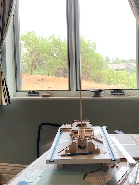
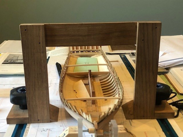
Before planking any further, I need to make sure the partners are correctly aligned (port to starboard) so the mast is plumb. With my digital level, I made sure the window frame (in the background) is plumb. I shimmed up the building board to level and then aligned the temporary mast pole with the window frame. Maury
-
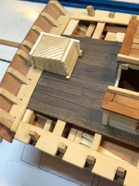
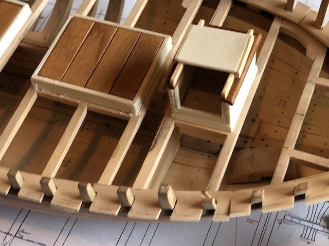
The tedious process of filling the notches in the covering board continues. Once sanded they will be almost invisible. Wheelbox done. Axle is set in but the wheel will be a challenge. "American Fishing Schooners" (Chapelle) says the wheels were wooden until the middle 1860's.
-
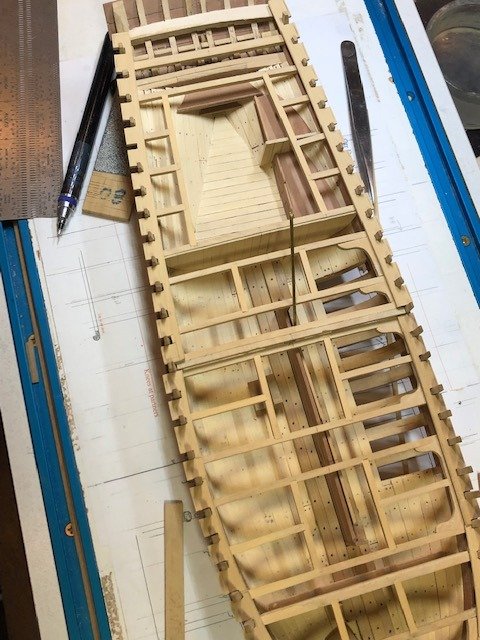
The mast steps are in so I can start on the deck planking. Gluing in the covering boards comes first. Weighted down with cross beams for the glue to set. The main deck planks are parallel to the center line. The quarterdeck planks are parallel to the sides of the cabin trunk. With one plank in on the starboard side abutting the cabin, I worked across the section behind the cabin. The wheelbox is being built up around a plug cut to shape. Edges will be sanded and the starboard side will be put on next, followed by the roof. Maury Maury
-
The mast steps are in so I can start on the deck planking. Gluing in the covering boards comes first. Weighted down with cross beams for the glue to set. The main deck planks are parallel to the center line. The quarterdeck planks are parallel to the sides of the cabin trunk. With one plank in on the starboard side abutting the cabin, I worked across the section behind the cabin. The wheelbox is being built up around a plug cut to shape. Edges will be sanded and the starboard side will be put on next, followed by the roof. Maury Mary
-
Before I can proceed to the deck planking, I need to get the mast steps in place. That means temporary masts to get the 4% rake (taken from the plans). Since there are no records of the masting, I've got to make some estimates. In all of my sources, I have not found any specific mast measurements. From drawings and photos of similar boats built around the same time (1845-50) I've arrived at average mast heights (they are lofty, indeed). Foremasts seem to average 84 - 87% of length between perpendiculars and mainmasts 86 - 88% of length. Similar relationships to moulded beam confirms these mast lengths. The original plans from Chapelle show the diameters at the deck level between 10.5" and 11". Chapelle's American Fishing Schooners has a discussion on diameters and tapers that line up closely with the above comments. Interesting point says the tapers were not the same on all sides (after side of masts should be straight from boom to the trestletrees) but this rule was often not adhered to. The most clear illustration I've found is from the cover of Chesapeake Bay Schooners, by Snediker and Jensen. It shows a taper from deck to top of about one-third (from 11" to 7.34"). Does anyone have any better information or source? Maury
-
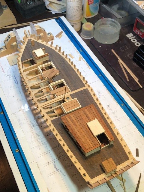
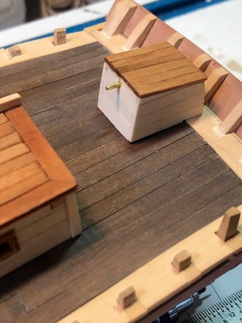
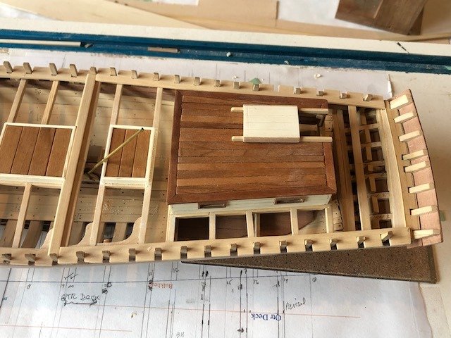
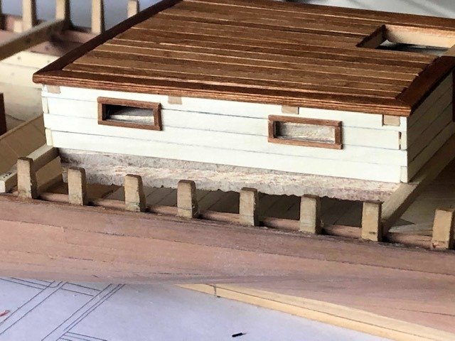
With the 2nd mate away at a reunion, I had a ot of time to work on some details. Cabin has been finished except for the doors for some time. Just set on the frames. The covering boards are done except for gluing them in place and inserting the LITTLE pieces outside of each frame. The hatch coamings are in holly and are two parts: Inner that goes inside the frames and provides the ledges for the covers and outer that sits on top of the frames. The pieces are lap-jointed. The companionway sits on top of coamings. Not glued in yet and the doors are not yet made. The hatch covers are cherry (scrap left over from a prior build) and finished with some walnut Howard Restor-a-Finish to provide some contrast. Some finishing left to do on the hatch coamings. And a lot of dust removal to be done. Maury
- 308 replies
-
- 11
-

-
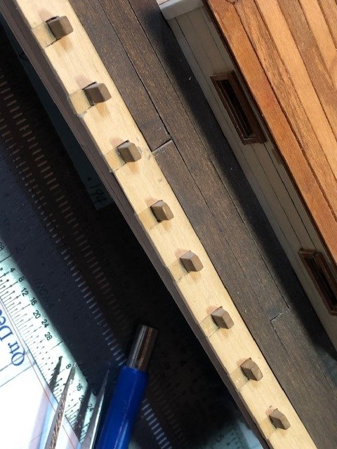
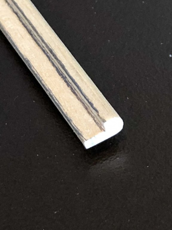
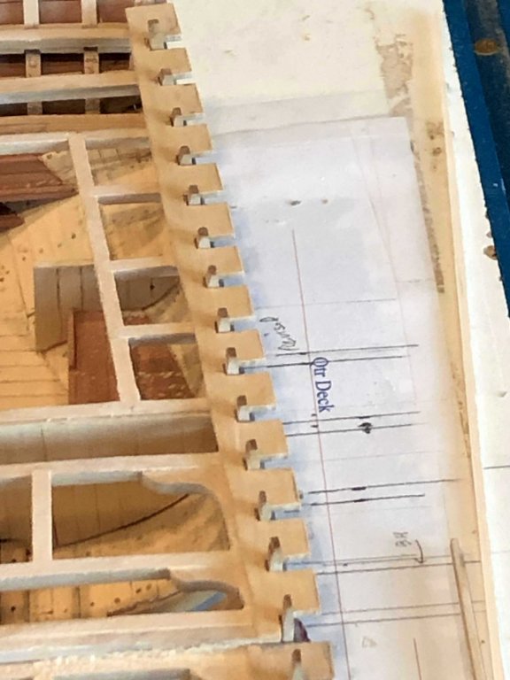
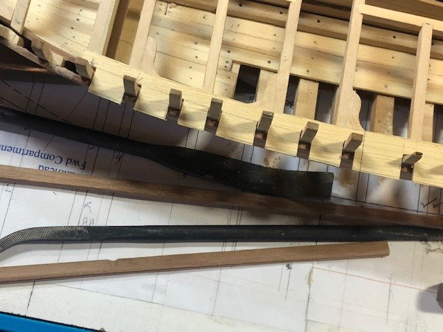
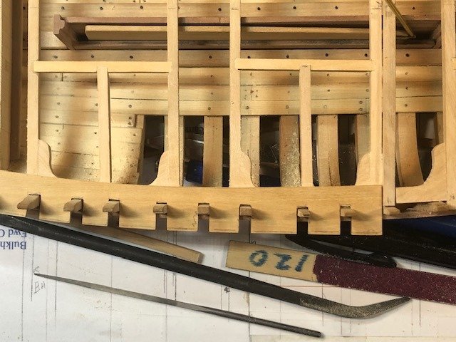
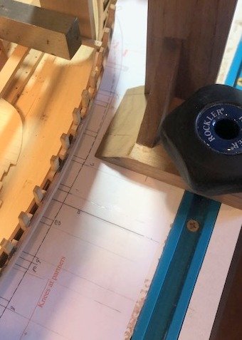
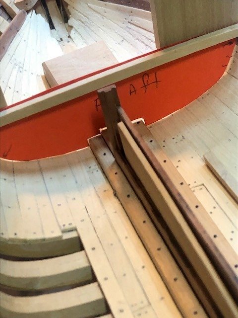
Covering board segments roughly trimmed to shape (net glued in yet). Inboard about 6" wide from frames, outboard just proud of planking. The bull nose was scraped to shape and the underside routed out on the mill. Pencil lines are drawn just for the photo...will not be visible once installed.
-
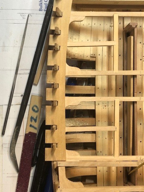
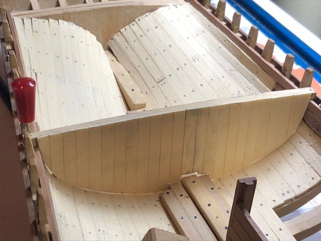
Two full days of cutting and filing and the port side covering boards are ready for final trimming. It took three pieces for the forward board because of the bend in the deck at frame E through frame K. They will fit a little bit more snugly against the frames when glued in. Biggest gap is about 1/64th". Inboard width from frame to edge will be 6" (1/8" at scale). Outboard side will be a hair proud of the adjacent planking. Maury

- 308 replies
-
- 11
-
-
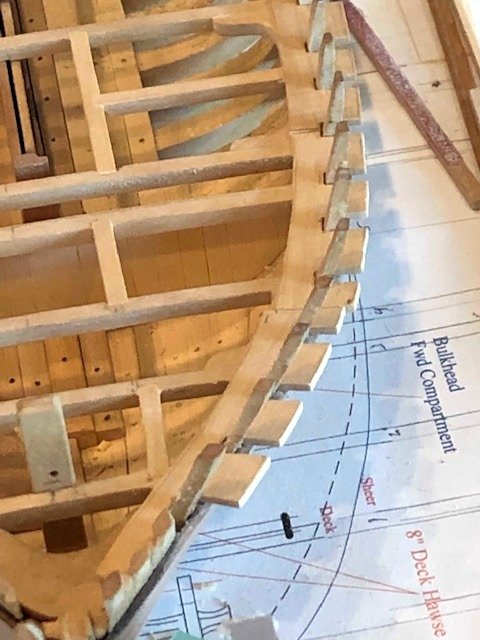
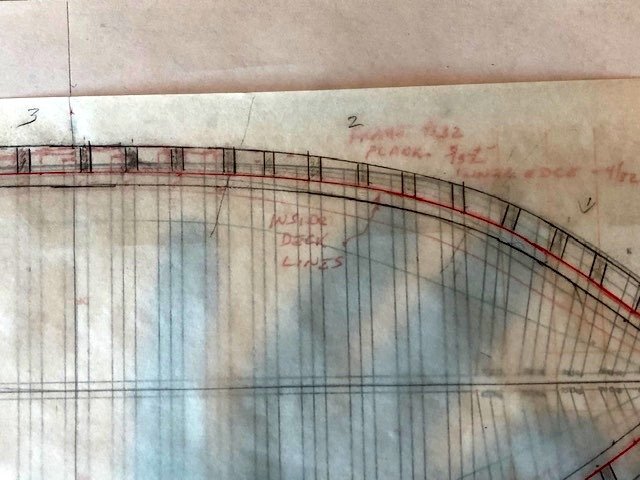
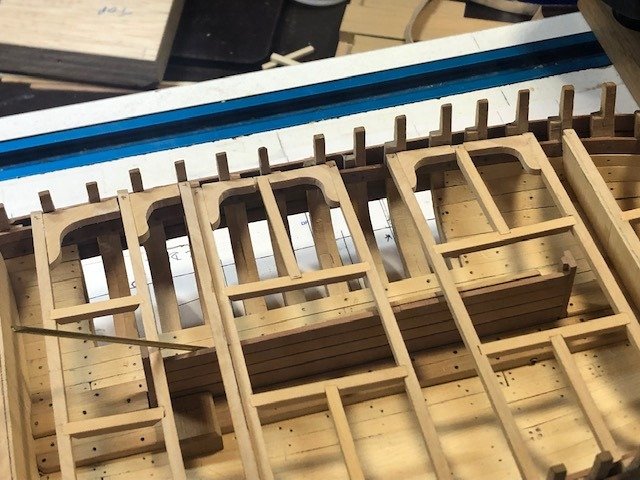
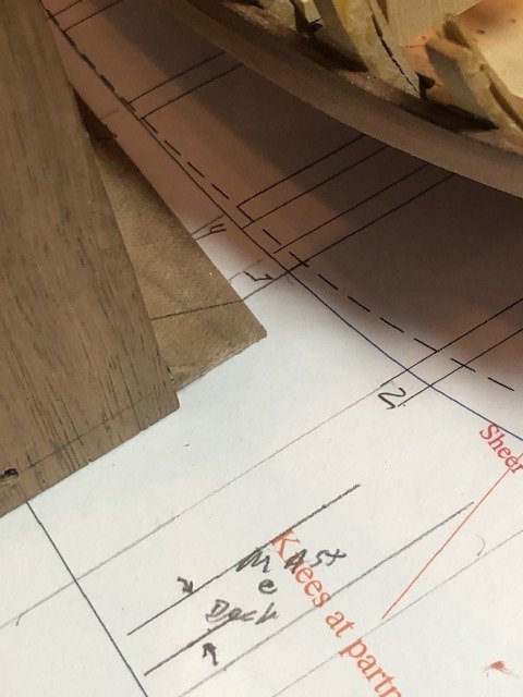
I started on the covering board. First I created an internal deck pattern from my original drawing and adjusted it to "as built". After laying it on the deck, I then laid a steel rule up against both edges of each frame and marked the pattern. The covering board will be 6" (1/8" at scale) wide inboard from the frames, 6" for the frames and another 6" outboard of the frames. This allows it to cover the edge of the plank with a little to spare. I can now make a template for the board. I used some 1/32" scrap material and transferred the frame locations onto it. After a lot of filing for fine adjustments, I have a good pattern for making the piece from box wood. So much sanding/ filing, card stock would have never worked. Transferred to box wood. Still some minor adjustments to mate the slots to the frames. This is about 15% of the total I'll need, and I have the technique down now. Maury
- 308 replies
-
- 12
-
-
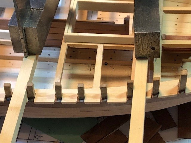
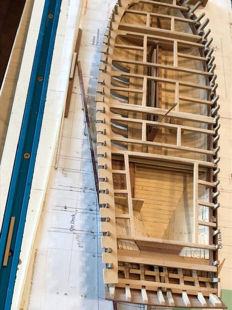
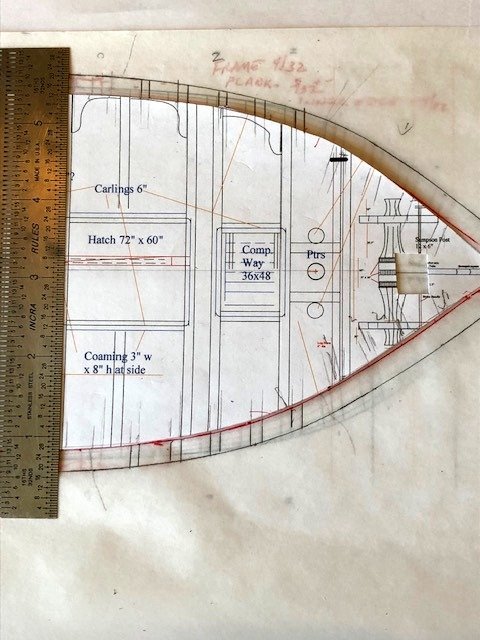
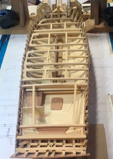
Some more progress. Lodging knees are in place. Carlings need to be added on the quarterdeck. Then on to the covering board. It goes from outboard of the waterways out to the outer edges of the planking. Complicated because it has to be notched for every frame top. I'll work from the inside-out, put fillers outside at the frames and finish the outer edge below the scupper strake. It will be box wood so will provide a pleasing stripe above the Swiss pear wales. Maury
-
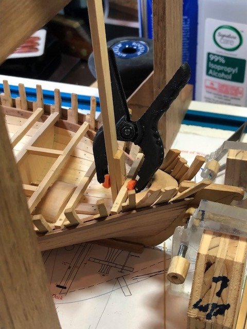
Sampson post being installed. Gantry is used to keep the post perpendicular and plumb. Maury
-
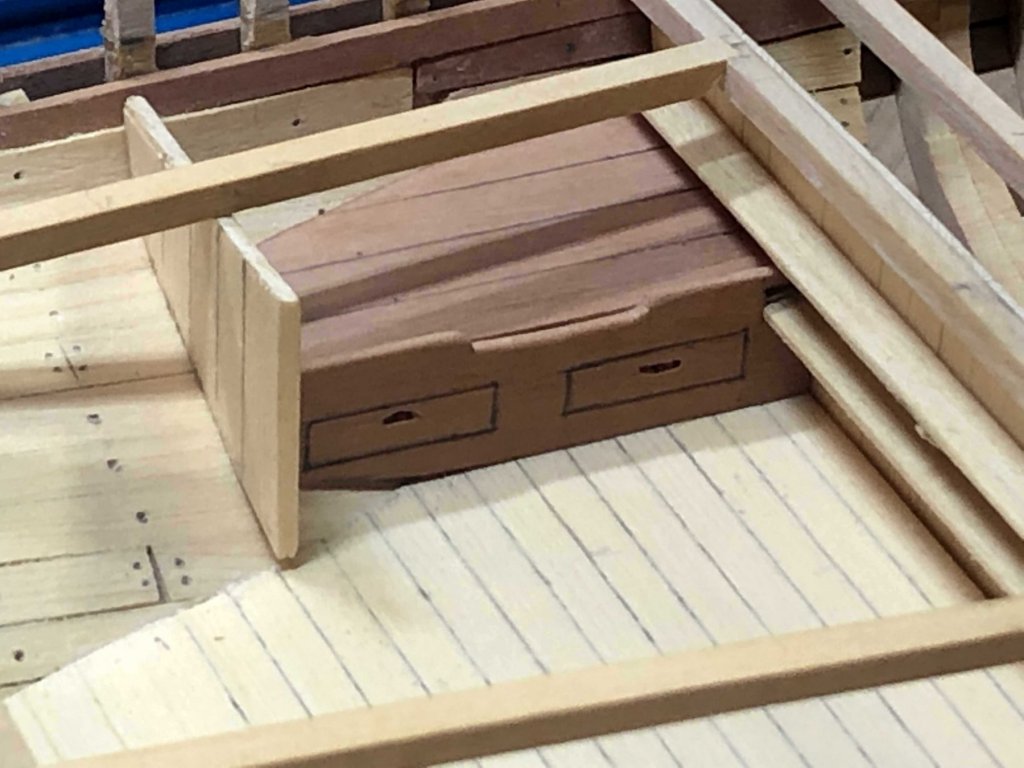
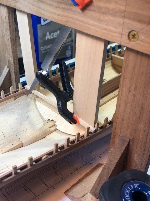
The carlings on the sides of the hatches are in. The vertical brass tube near the end of the centerboard trunk is protecting the lifting / lowering rod for the centerboard. Maury
-
I did some interior work on the cabin: After putting the top of the cabin in place, nothing can be seen inside. I don't think I'm going to build any more furniture. Maury
-
I'm looking for a cabin layout or floor plan for a bay schooner circa 1845. I've searched my collection of Chesapeake Bay schooner sources, etc. and have found such plans only for much larger boats. Anyone have photos, sketches, or plans for a boat like this (cabin size: 12 -13' long x 12' + / - width with 6' of headroom for maybe 60% of the area.. Thanks in advance, Maury
-
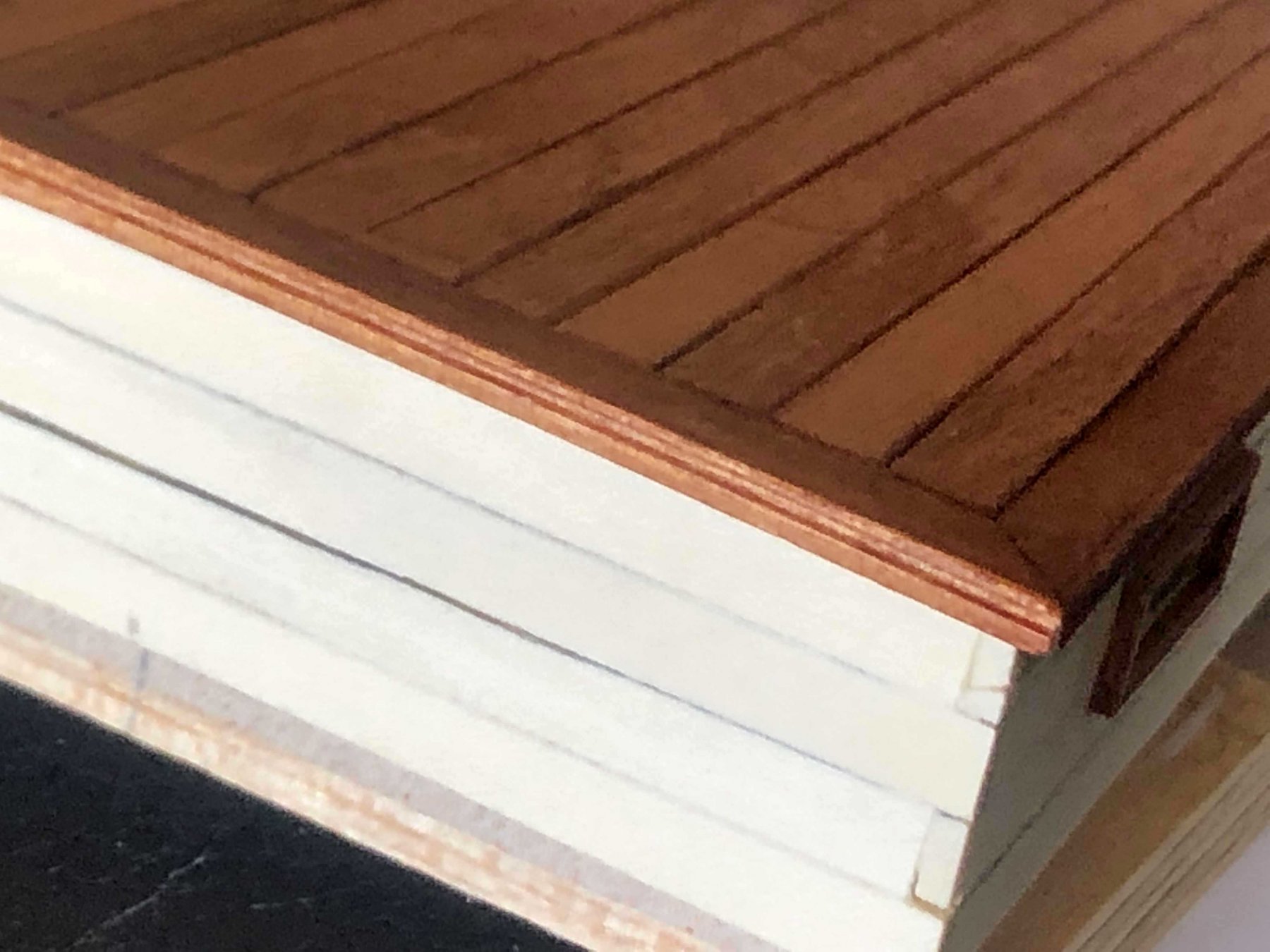
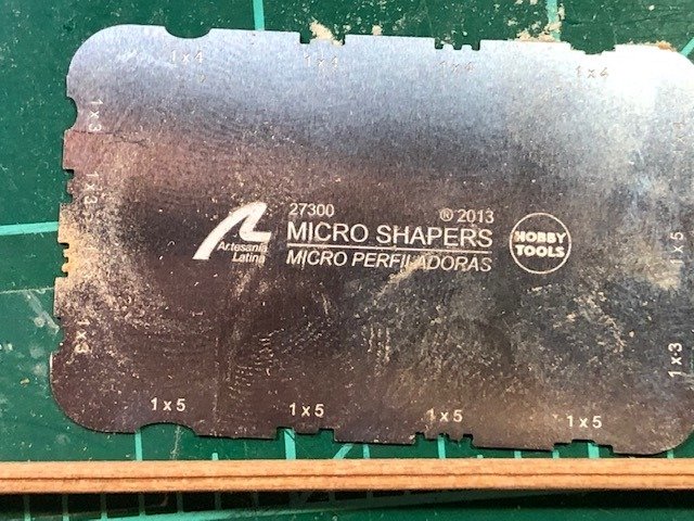
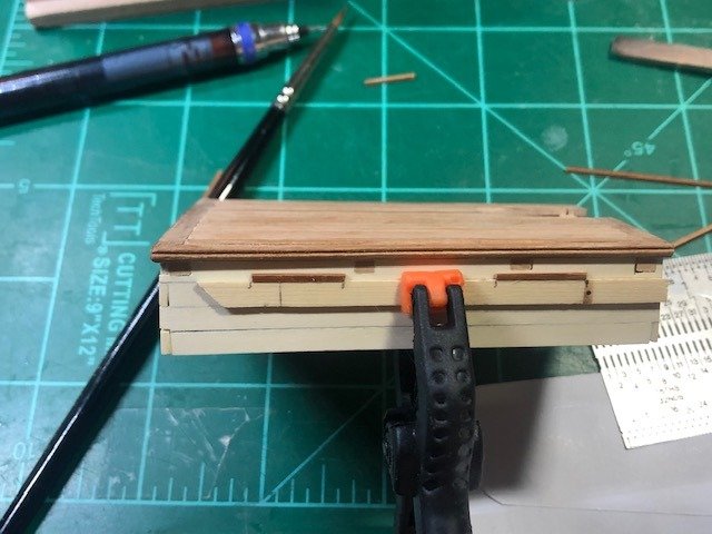
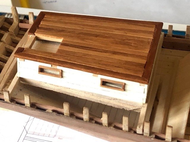
More work on the cabin. The roof has a molded edge. I used some scrap left over from my Fair American build of many years ago. The molding was scraped with a handy little tool from Micro Scrapers (set of three various patterns for a few dollars). Roof edges and planks installed(above). I used a straight-edge to align the moldings around the windows. A coat of Watco Teak applied. The corners, the companionway and doors still need to be built. Maury


-
Small diversion... I worked on the main cabin. According to reliable sources, the planking was "log cabin" style, sides and ends overlapping alternately. I cut a pattern block to the inside measurements and started planks from the bottom-up. The planking will rest on beams and carlings. Corners touched up on the circular sander. There will be a 1 x 3" lap at each corner to protect the end-grain of planks. Work on the roof to follow. Maury
-
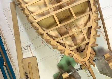
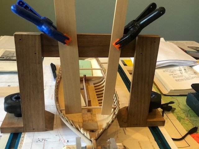
For Bruce and those sending PMs, following is more detail on the gantry. Credit to Ed Tosti [EdT]. Admin may wish to re-locate this to another place (Tips?). The basic gantry has two base plates that attach to the building board with T-bolts and knobs. The base plates are tapered to a point on the inside (more about this later). Attached to the base plates with a lap joint are vertical pieces (tall enough to accommodate your model(s) and a cross beam at the top (on the back edge of the verticals) that is perfectly parallel with the baseboard. This allows accurate measurement from the top of gantry to any point inside the model. The verticals must be plumb on both faces (side and end). A triangular reinforcing block connects the verticals with the base (2nd photo). Two screws on each end of the cross beam insures that the entire gantry remains square. (Reinforcing block) This photo shows braces clamped to the front edge of the cross beam. The front edge of the cross beam mates with the back side of the verticals. The guides clamped to the cross beam are helping to place the deck beams at the same place shown on the plan. A thin pencil line on the tapered edge of the base marks the back edge of the verticals and front edge of the cross beam. This allows perfect alignment from the plan on the board to a guide clamped to the back of the cross beam. Braces clamped to the cross beam also permit pressure from above for gluing when you can't use a (regular) clamp. Pencil line on tapered part of the base plate is parallel to the vertical and appears at an angle due to distortion from the lens and the angle of the photo. Maury
-
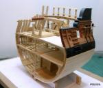
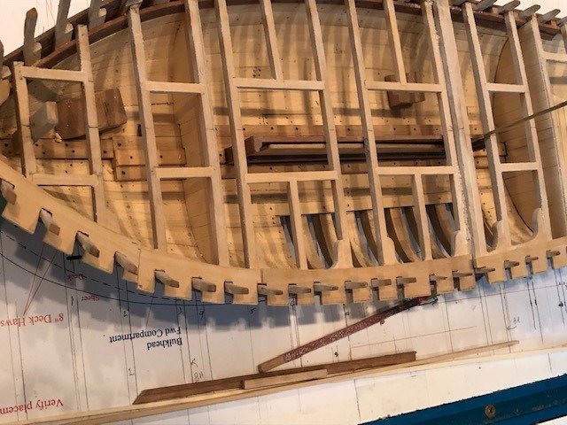
With the ceilings complete, I can start laying out the beams. The boat was taken off the building board and the deck layout plan replaced the frame plan. The deck beams are conjectural (nothing from Chapelle). Key beams surround the mast partners and all the deck openings (companionway, holds and cabin). There is a bulkhead just aft the companionway and just forward of the cabin. The card pattern was taken off the closest frame and adjusted for fit. I made the bulkheads before I glued a beam in place. Next comes the beams. First is most forward (key) beam, then the forward edge of the cabin. Test fitted before gluing. The gantry is critical in lining up locations from the deck plan. More details on this on request. Maury
-
Walnut Wood
Maury S replied to scottpollack's topic in Building, Framing, Planking and plating a ships hull and deck
If you are trying to avoid the box and pear, look into cherry. The grain is tighter than walnut and it ages beautifully. M