HOLIDAY DONATION DRIVE - SUPPORT MSW - DO YOUR PART TO KEEP THIS GREAT FORUM GOING! (Only 24 donations so far out of 49,000 members - C'mon guys!)
×
Maury S
-
Posts
1,490 -
Joined
-
Last visited
Content Type
Profiles
Forums
Gallery
Events
Everything posted by Maury S
-
I think you will find the tall strips will take on a bend if stored vertically. (been there, done that.) The wood should be stored flat (use tubes or boxes if you like to keep pieces sorted by size.) Maury
-
 Transferring top of beam measurements from plan to the boat. The camera angle distorts where the line lands. I now have to measure down to the top of the clamp. Maury
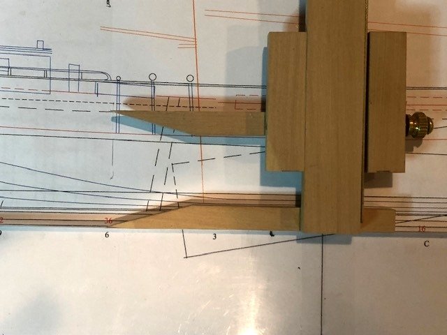
-
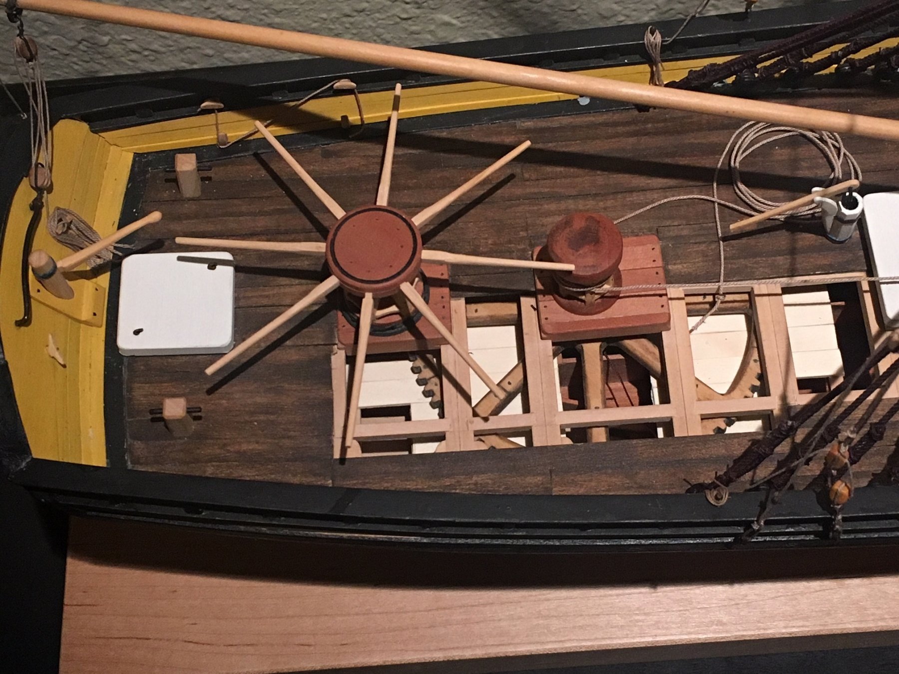
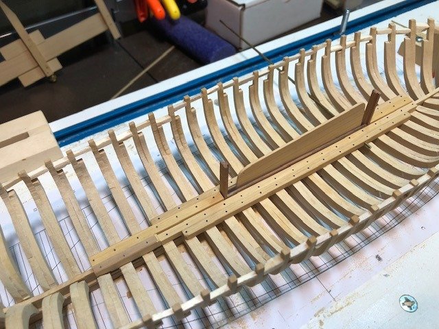
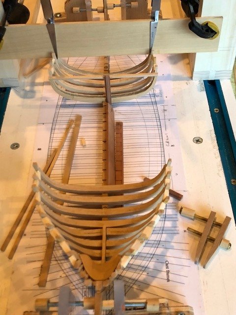
All the keelsons are in. There are several pieces holding things together since the frames set into the side of the well. The cross section design was shown in an earlier post. A note about the simulated bolts. The use of the monofilament line came from Ed Tosti (EdT). I have developed a technique with the line after several models. If I can pre-insert them I do so. This involves slicing a taper in the line to aid in insertion in the drilled holes. I push the line through the hole from the finished side of the plank or beam, dip it in CA and pull it back through the hole until flush on the under side. Then it is clipped off with flat nippers. This way, there is no CA residue that needs to be wiped off (with acetone...nasty stuff). I also run a soldering iron over the exposed ends of the line, which finishes it off more like a bolt head. Maury

- 308 replies
-
- 13
-

-
Ed, I did use a spacer in the CB well when I was gluing up the frames. I think it's an illusion in that pic. The next post will show all the keelsons glued in place with the centerboard in the well. One side of the well will be fully planked. The other not so much. The challenge has been to keep the pivot pin aligned as it must go through all the keelsons, the CB well planking and the centerboard. Thanks for your comments...always appreciated. Maury
-
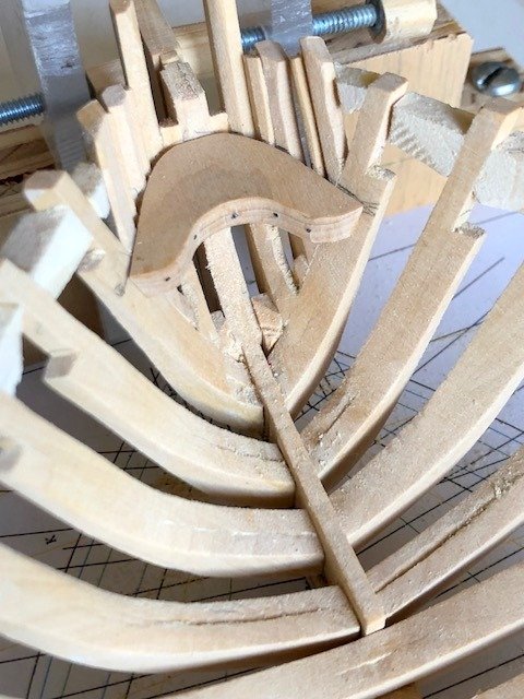
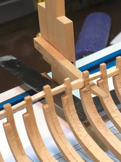
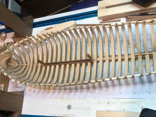
The last (half) frame going in. A beam held from the gantry puts pressure on the frame at the keel/rising wood while the glue dries. A square lines up the outer edge of the frame to the waterline on the building board. The temporary cross member supporting the CB log has been removed. I don't know how I would have held parts in place without the gantry / building board setup. All the frames are in. While the spacers between the frames distort the fair line of the tops of the frames in the photo there is still a lot of fairing to do . Right now I'm smoothing the tops of the frames at the keel for the keelsons. The keelsons will add a lot of support. Sanding block, straight on one edge, curved on the other can be seen on the right. Maury
-
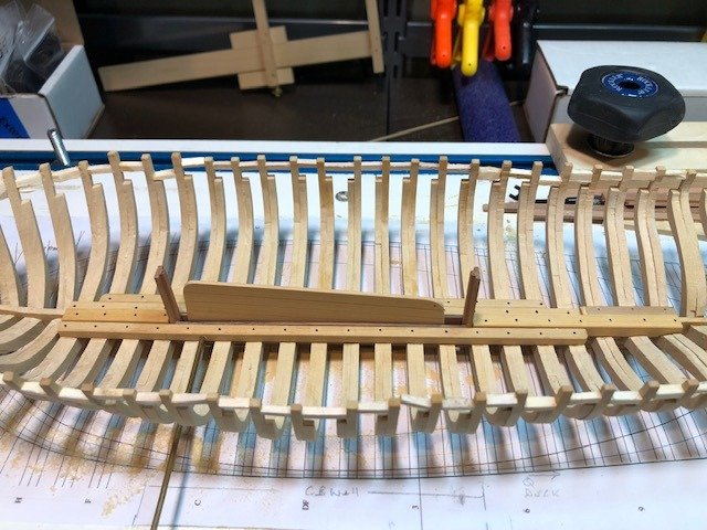
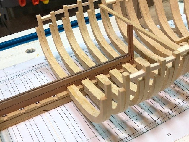
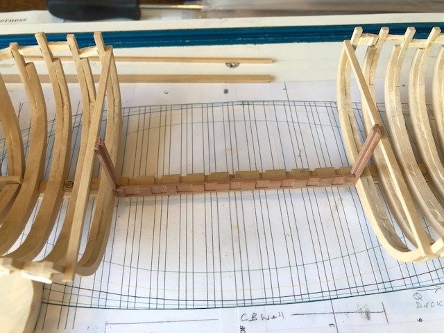
It's been a while...Lofting and installation of frames continues. The final frames are those that occur at the centerboard well. That makes them all half-frames and the jig for those is the same as the half frames fore and aft. On the port side, the frames fit into the lowest plank of the centerboard well. On the starboard side, the frames notch into the keel / rising wood and butt up against the CB well planking. Multiple keelsons will go over the frames on both sides. The hole for the CB pivot pin can be seen in the planking (right side). Since the keelsons will cover it, they (the keelsons) will have to be bored out to allow for potential replacement. The horizontal piece supporting the top of the CB well log is temporary. Maury
- 308 replies
-
- 13
-
-
The first two planks of the centerboard well are in and the hole for the pivot pin aligned. While I'm talking about the centerboard, let me throw out a question about the controlling (raising and lowering) the board. It's rather large (5 - 6 feet by 15 - 16 feet) and would have been weighted. I've found no drawings or photos showing this detail. Some research has indicated that chain would have been used. Might it have been cranked up on a drum or connected to a simple pendant / gun tackle strung from the mast (which is just aft the aft part of the well)? Any thoughts will be appreciated. Maury
-
Echo by davec - FINISHED - cross-section
Maury S replied to davec's topic in - Build logs for subjects built 1751 - 1800
Dave, Nice job. I ran into a similar issue with the pumps intersecting the walls of the well. You seem to have made a reasonable adjustment (and maybe not the last). Maury -
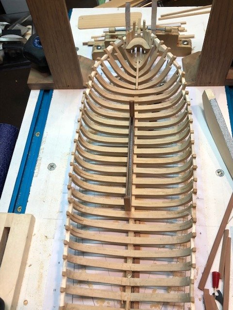
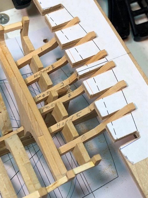
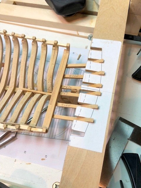
Frame 16 is now installed and the post and horn timbers are temporarily in place to make sure everything glues up properly. The outer two timbers butt against the aft side of the frame so the joint is inherently weak. I'll put in some cross-framing to stabilize everything before removing the jig. All pieces fit nicely...no major trimming necessary. By the way, the jig has a crown (bend) in it to match the eventual tops of the timbers. All I have to do is chisel / sand down to the top of the jig. After that's done, I'm on to the remaining frames in the area of the centerboard well. They are a series of half frames butting onto the lowest well plank (see photo) on one side and the keel / rising wood on the other. I have to put in another CB plank pair and set the centerboard in place first so I can drill for the pivot pin. Maury
- 308 replies
-
- 12
-
-
Very nicely done. Maury
-
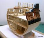
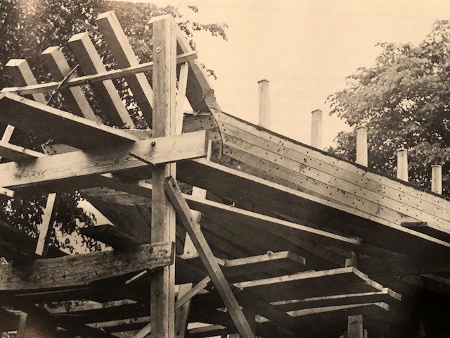
A lot of time since the last post...traveling, other commitments, etc. I finished frame #15 (second to most aft), which includes mortises for the post and horn timbers that support the transom. Post timbers abut the stern post, the horn timbers are the ones further out. A John Clayton photo from Dana Story's "Building the Blackfish" provides some insight: To support the ends of the timbers, I built a jig to position them. It clamps to the square frames on the building board. Now that they are temporarily in place, I can better fashion frame #16, as the timbers rest on it. Maury
- 308 replies
-
- 14
-
-
I had to go over Admiralty Models' Drafting Workshop materials to understand how to use diagonals (complicated). I expanded the stations to five since three will always result in a smooth line and ran checks. The original lines are smooth. Waterlines projected to the half breadth. I then took care to determine exactly where the original station lines fell in relation to final frames and re-drew the waterlines on the half breadth. From there I projected the center of the frames back to the body plan and the variations are as expected due to the width of the frames. A whole afternoon of modifications to the plans. I'll start removing the errant frames tomorrow. Maury
-
The four half frames at the stern are installed and I've made some serious errors along the way. They are not fair. Not even close. I went back to the original Chapelle drawing and compared the body plan with my framing plans and they do not line up. Going back over the lofting instructions from Wayne Kempson's tutorial which I followed completely, I have determined that I probably chose the incorrect spline tool in projecting my body lines and the waterlines on the half-breadth. I probably used the "spline by control points" tool rather than the "Spline by fit points" tool. The difference shows up where there are sharper curves (like near the stern). I've copied the body plans for the aft-most frames from the original plan (they correspond very closely to frames 11, 13 and 15) onto my body plan and I'm re-lofting the water lines aft of frame 9. I'll have to replace the frames from 10 or 11 aft to 15.🙁 Maury
-
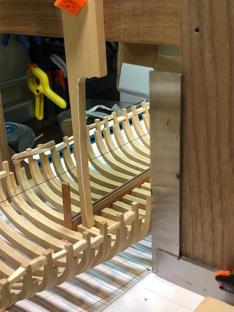
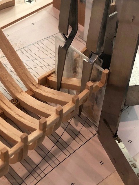
Installing Frame 12 against deadwood. The jig described earlier...frame is clamped to the Plexiglas sheet glued to machinist square aligned with plan on building board and other square lining up top of frame. Slowly proceeding. Maury
-
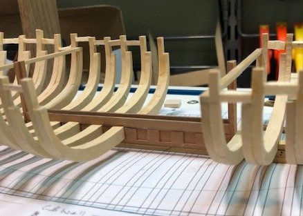
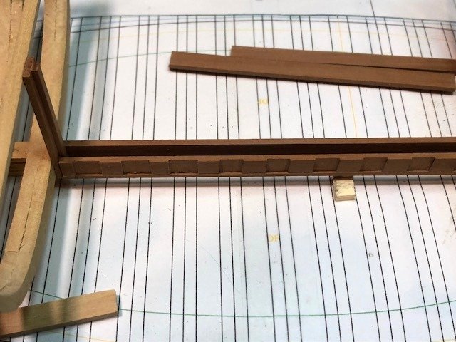
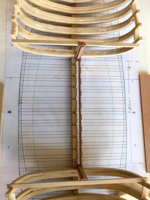
While lofting and building the remaining frames at the stern, I've diverted to lining up the frames at the centerboard well. Before the frames can be properly lofted, I need to know exactly how the CB well lines up. The port side of the lowest plank of the well (where the ends of the frames seat) has been installed. The well sits at the outer edge of the rising wood and has a slot 1" wider than the thickness of the centerboard. There are rabetted logs at each end of the well that tie into the frames at the bottom and a deck beam at the top. The tops of those logs are held in place with temporary spanners rather than the final beam. I can now determine the difference from the centerline for the port-side frames. Maury
- 308 replies
-
- 12
-
-
Hull filler.
Maury S replied to bluenose2's topic in Building, Framing, Planking and plating a ships hull and deck
If you must use filler, try Bondo (auto body filler). It comes in a squeeze tube which is easier to store and preserve. Maury -
An extraordinary story. Well worth the read. Maury
-
One reason for pumps to be in pairs (one to each side) is that the ship is often heeling to one side or the other so the effectiveness of the pump on the leeward side is greater. Maury
- 12 replies
-
- 4
-
-
- chain pumps
- dromons
- (and 2 more)
-
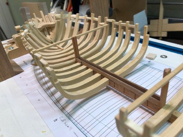
Back from vacation. Framing continues. Frame 10 is being held level as the glue dries. The section from Frame E to Frame 5 is where the centerboard case goes. The frames in that area require special handling. Basically the same treatment as the square frames seated in the deadwood, one side at a time. The frames on the port side butt into the centerboard case so will be sized to account for the case. Maury
- 308 replies
-
- 12
-
-
Thank you, I thought as much. A card profile was cut, transferred to some 9" stock and sanded to fit. Simulated bolts added. The height was carefully measured from the profile and transferred to the inside of the forward-most cant frame and stem. That bow area is now very solid. Maury