HOLIDAY DONATION DRIVE - SUPPORT MSW - DO YOUR PART TO KEEP THIS GREAT FORUM GOING! (Only 24 donations so far out of 49,000 members - C'mon guys!)
×
Maury S
-
Posts
1,490 -
Joined
-
Last visited
Content Type
Profiles
Forums
Gallery
Events
Everything posted by Maury S
-
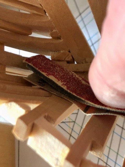
 There is a lot of sanding / fairing to do around the cants and hawse pieces. It's a tight fit. I wrapped a piece of 80 grit paper around the end of a riffler file and it gave me plenty of pressure to sand in the restricted space. A lot of sanding ... I've looked at dozens of photos and drawings of similar boats under construction and have not seen a deck hook or breast hook in any of them. I'm thinking a deck hook might stabilize and simplify things for later. Maury Maury
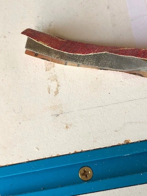
-
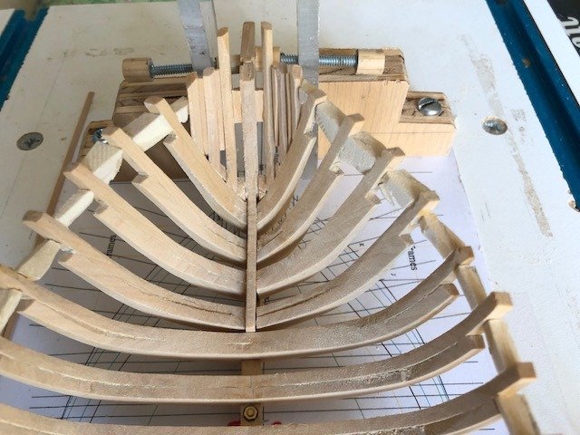
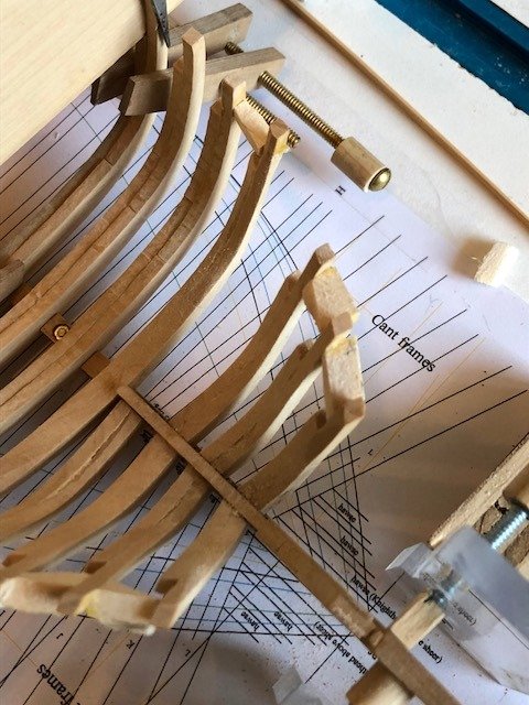
Hawse Pieces going in. Translating Wayne's practum on lofting these pieces took a couple of iterations to get right. Once done correctly, an "Ah ha". They look pretty ragged because of the filler spacers between the hawse timbers, but they line up with the plan on the building board. Once the glue has dried, I'll fair them and put in some additional support. Maury
-
The offending cant frame is replaced and the first eight frames are roughly faired on the inside. Do I put the Hawse pieces in now or later??? Maury
-
Druxey, Thanks for your comments. It's odd to see a mast off-set, but it seemed to work for them. Most of the other centerboarders I looked at before deciding on this one had the board going through the center of the keel, requiring beefing up the keel along the mid-section. I'm not sure that having 9 frames end on the CB well structure would be all that strong, but take a look at the keelsons in the drawing I posted a few days ago. A lot of meat there. Maury
-
One of the cant frames didn't line up properly, so it's removed for replacement. Maury
-
Wayne, While we're on it, in the lofting process you've described in your practum, should we be using splines by "Control Points" or "Fit Points"? It seems to me that if we have to go back and adjust waterlines and body plans that do not appear to be fair, we need to use Fit Points. Am I correct here? Maury
-
Chuck, You certainly are bringing kit making to a new level! Maury
- 421 replies
-
- 4
-

-
- medway longboat
- Syren Ship Model Company
- (and 1 more)
-
And to add to Druxey's comment, while the centerboard is off-set (to port), the main mast is set off-center (to starboard) to counter the effects on the ship's handling. While the setup is unusual, it is not unique. Maury
-
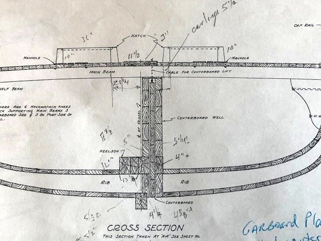
Peter, The Centerboard setup was one of the reasons I chose the boat. The well is integral to the design of the boat. The keelsons are built up in the area as can be seen on the drawing below. This is a cross section of the Smith K. Martin from the HAMMS Collection at the Smithsonian. It shows the details as well as anything else I've found. The frames attach to the bottom plank of the well and not the keel, so everything is tied together. I plan on leaving several well planks off to show off the centerboard and its operation. Maury
-
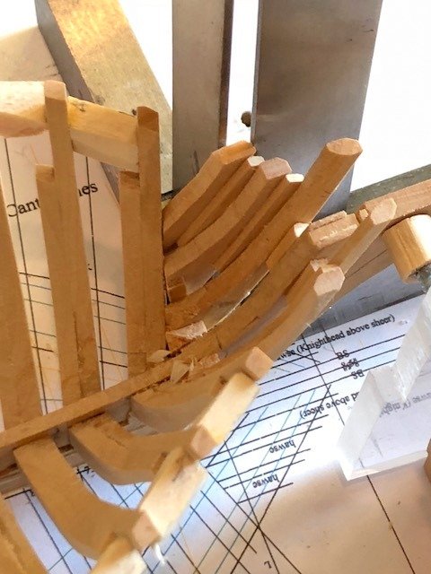
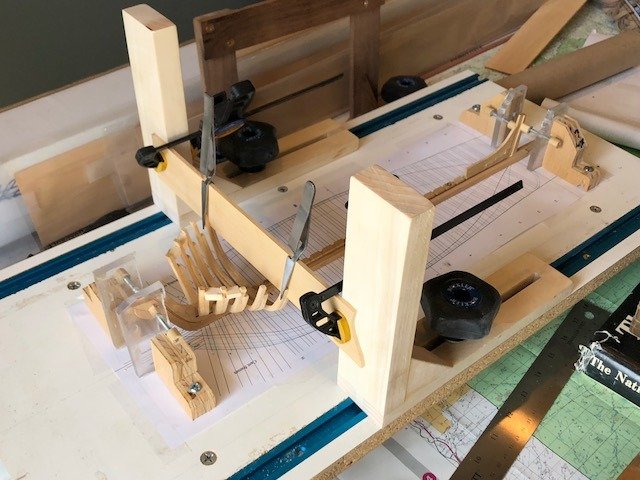
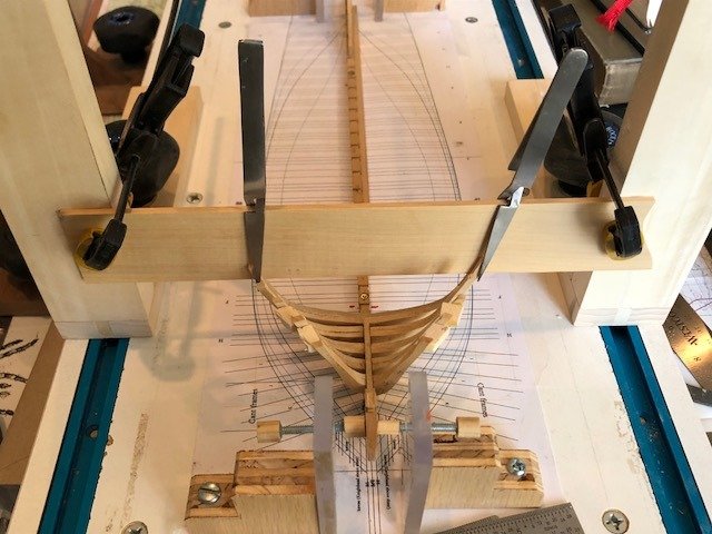
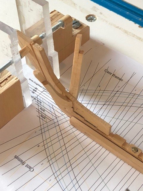
Installation of square frames: This (Fr. H) will be the only square frame I install at this stage so I can fair the inner faces of the cant frames. The process is precise and relatively simple given the building board and its accessories. The building board had the full-breadth plan pasted-on. There are two Building board square frames [BBSQFR]. Their faces are square to the board. The BBSQFR faces are lined up with the aft lines of the frame on the plan using a machinist square. A long 1/8" (thickness of the frame half) beam is set on top of the futtocks #3. The tops of Fut. #3 were cut precisely to length and the top timbers were cut proud. Since the beam is the same thickness as the frame, the face of the beam, clamped to the face of the BBSQFR aligns the aft edge of the frame pair with the plan on the board. Holding the Micro Mark digital level on top of the beam, I can make sure the frame is level side-to-side. The beam is clamped to the BBSQFR and the timber tops are clamped to the face of the beam. Ready for glue. Maury
-
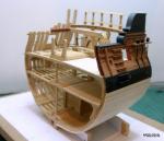
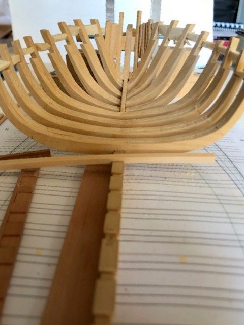
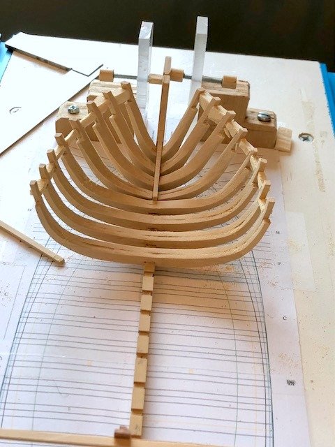
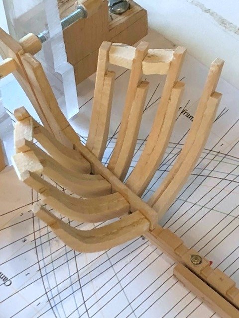
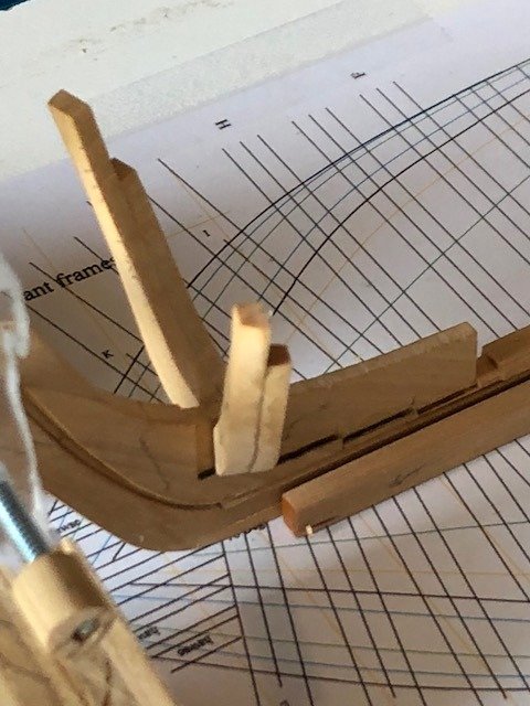
All 4 cant frames are installed. By the time I get the spacers put in, I think it will be quite stable. I built up the first square frame (H) to check on fit, process, etc. Aligning the fit over the rising wood is critical. A jig was built...just cutting the slots in a dummy piece of rising wood to accept the frame pair. The frame pairs are glued together and held with clamps (more clamps than shown in pic.) while the glue dries. I will bevel the frames while paired but before installation since the floor and futtock pieces are fragile. Maury
-
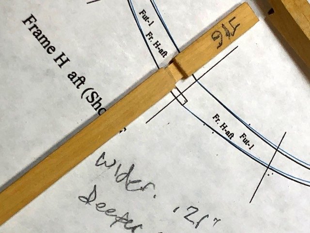
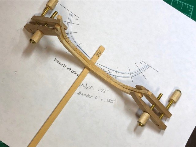
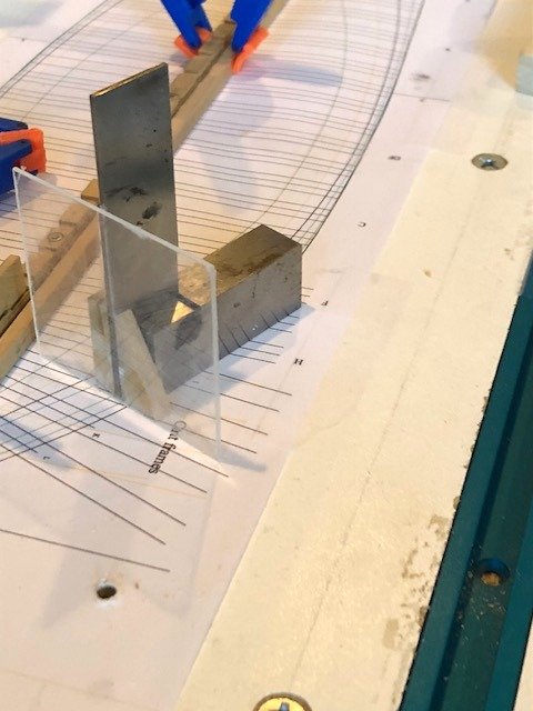
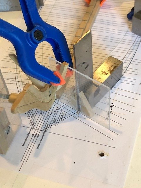
This is my first attempt with cant frames. Lofting them was only a minor challenge but could not have been accomplished without Wayne Kempson's "Drafting Ship Plans in CAD" posted on this site. I pasted the patterns on 1/8" (6" at 1:48 scale) box wood, cut them to the outside lines and trimmed them back for the bevels. The first set of cants lie at 70 degrees so careful sanding was required for a good seat. Holding them in place while glue sets is another challenge. I assembled a jig using one of my small machinist squares and a piece of clear acrylic. This allows me to keep the frame plumb at the same time as it is lined up on the building board. The frame piece is clamped to the acrylic plate and everything is lined up with the plan on the board. (The front braces for the stem had to be removed to allow room to maneuver.). End result of the first set shown below. They were allowed to dry over night before removing the jig. The next set will be done in a similar manner. I think some scrap spacers need to be applied at the tops between the frames. Maury
- 308 replies
-
- 12
-
-
Stern timbers and deadwood being glued to the keel. Once the false keel is on, I can put it on the building board. Maury
-
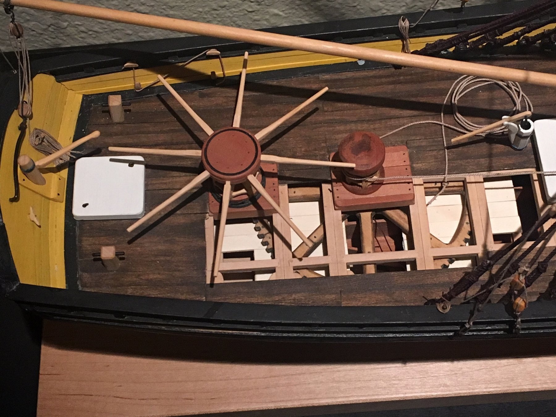
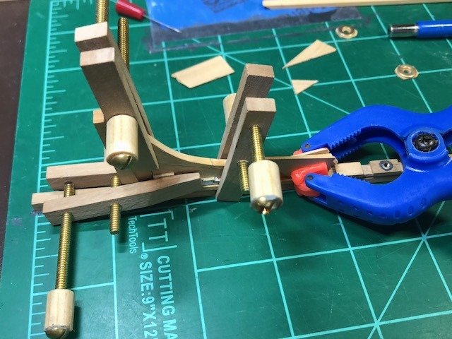
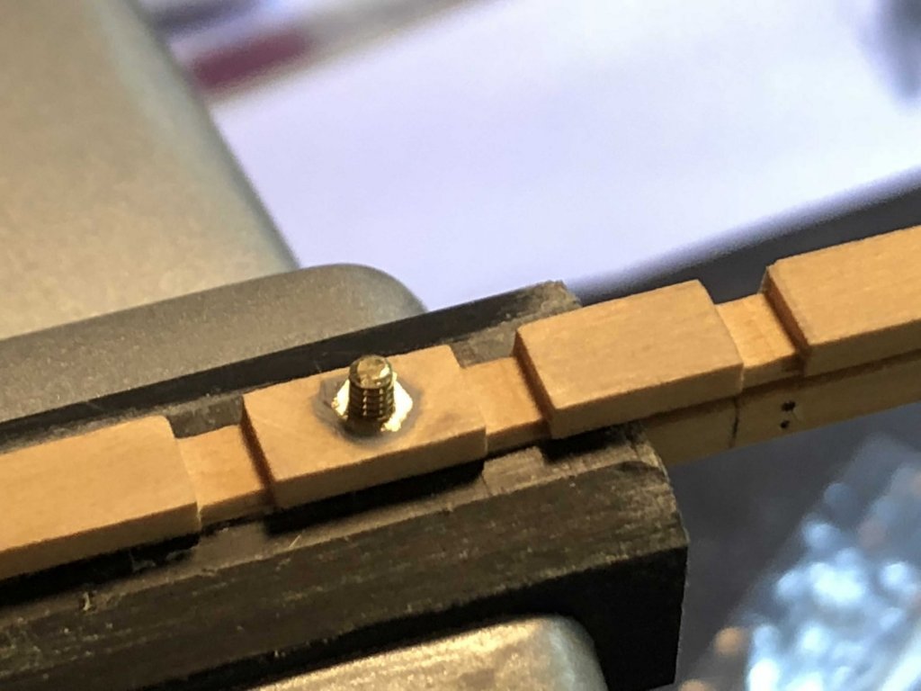
I received the 2-56 threaded rod and nuts. The nuts are buried in the rising wood and cemented with epxoy. There are two retaining bolts, each far enough away from the centerboard location so that the mounts will not interfere view of the partially dropped centerboard.
-
To darken glue, try mixing a little red and green food coloring to make a nice dark brown. Experiment with results. Not sure how this might affect strength. Maury
- 3,618 replies
-
- 2
-
-
- young america
- clipper
- (and 1 more)
-
Working on the deadwood at the stern. I'm king of limited without some of my tools so, ...more lofting to do. Maury
-
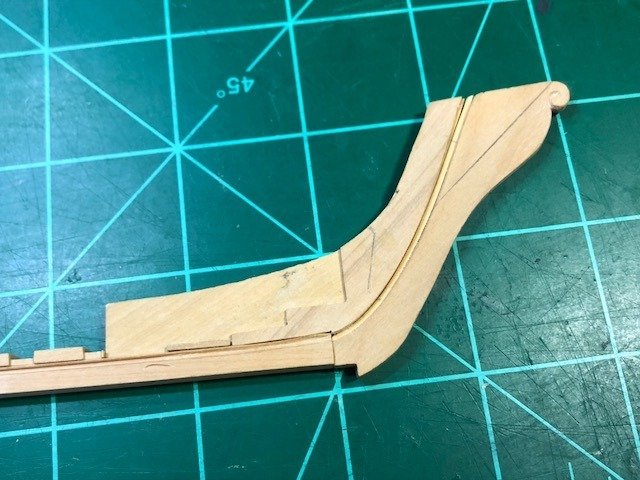
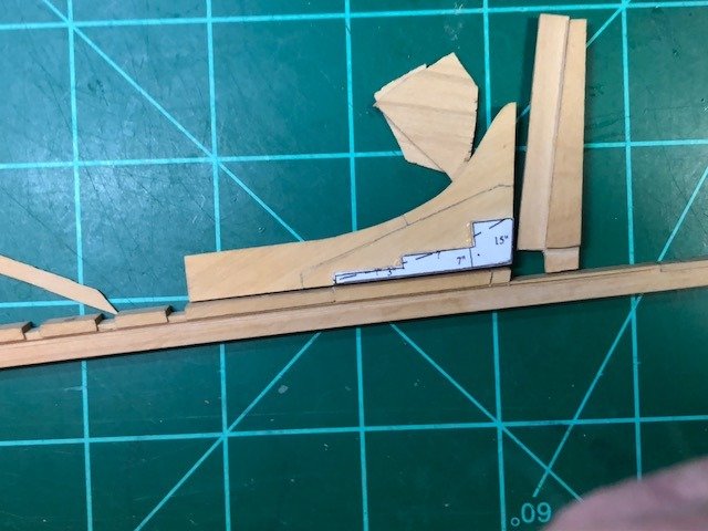
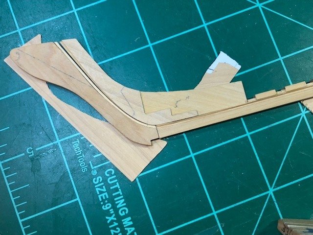
Stem wood in progress. The pieces are propped up with some scrap and the joints are tighter than they appear. The 4-40 brass bolts I was going to use to hold the keel down to the building board are too large (diameter) to safely go through the keel so I've ordered some 2-56 threaded rod with a .086" diameter. A 3/32" hole will leave enough meat on the keel which is 8" (.1668" at scale). The steps for the cant frames are 1/32" patterned wood added to the stem stock. It's easier for me than to uniformly chisel out the steps. Now that those thicknesses are established, I'm going back to re-loft the cant frames. I had originally drawn them butting up against an 8" stem but the new stem means I have to add 1-1/2' (1/32") to the frames. Maury
- 308 replies
-
- 13
-
-
I cut the sternpost. 93 degrees on the aft side, fore is 98.5 degrees. The tenon will fit into the keel but I don't have access to my mill for a while so I'll do the mortise later. Maury
-
More work on the keel. The rabbet measures about 2 1/2" wide. I started with a line and a scalpel and gave up after about an hour.. Back to the table saw and a .032 slitting blade set at about 1/32" deep. I started aft of the section where the keel starts to rise (about an inch aft of the end) and ended where the stern post intersects. The cut was brought to a sharp edge at the top of the keel with Swiss files. The section of the keel where it rises from 9" to 10 1/2" was cut and filed by hand. The lower edge of the cut will be most visible and I wanted it as perfect as I could get it. Enough for today. Maury
- 308 replies
-
- 10
-
-
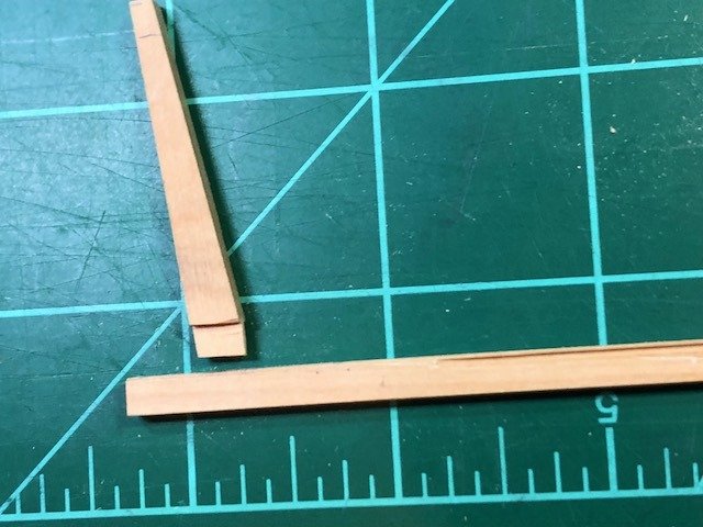
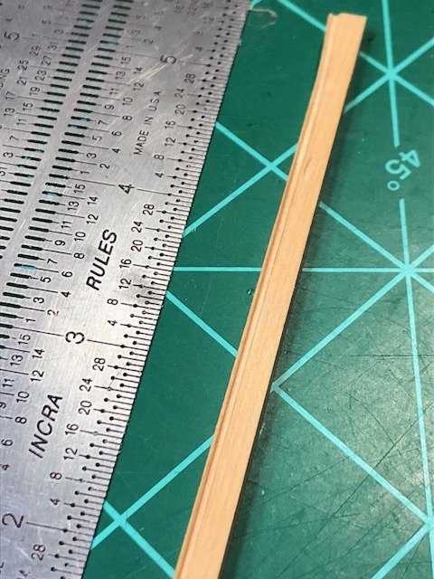
Taking a break from lofting in TurboCAD, I will start with the keel components. First done was the rising wood. The rising wood is 4" x 10", the notches are 2" deep and 8" wide after cutting out 1" on each side. All work done on the Byrnes table saw with a sled. The piece tends to bend with so much meat cut out so it's being held to a piece of 1/4" slab until it's glued in place. Maury
-
Roger, I think you can get much more aggressive on the paper grit...like maybe down to 120. As you said, experiment. Maury
-
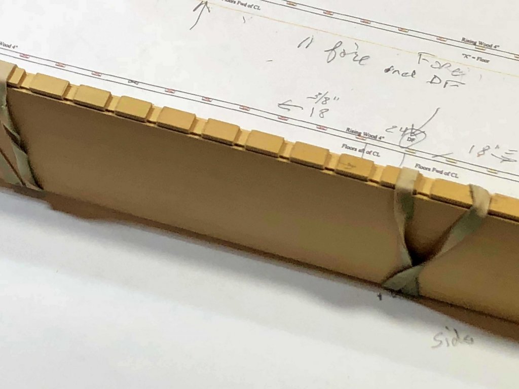
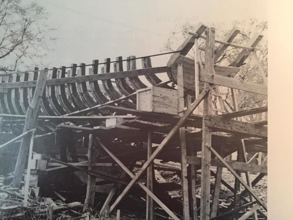
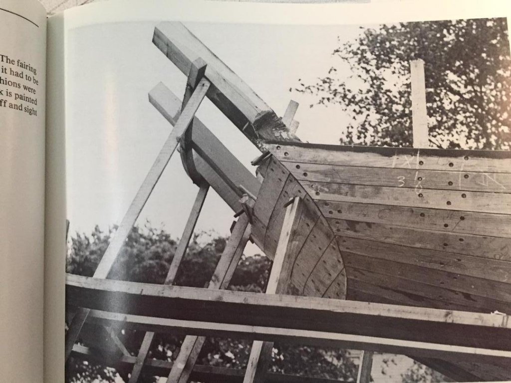
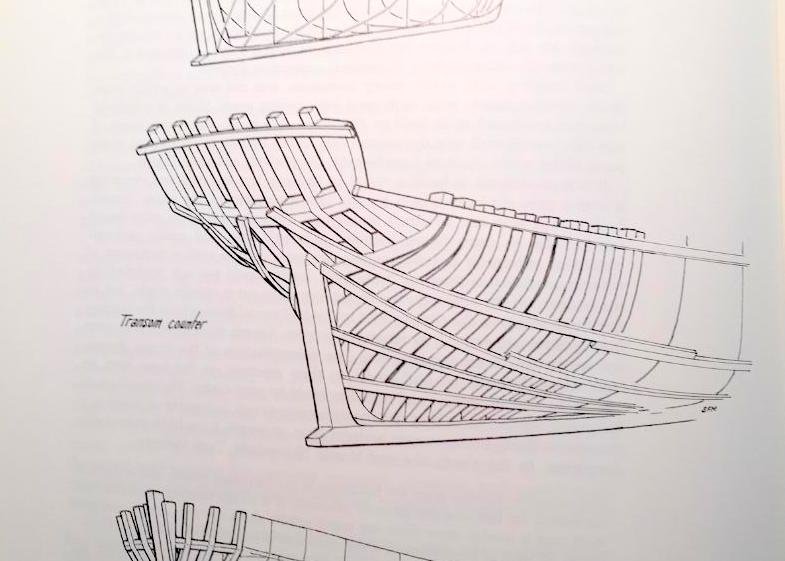
While lofting (and re-lofting) I've run into a few questions. Latest ones regard the framing of the transom area. Randy Biddle (Windship Studios) has provided me with a lot of photos and drawings from the region that are proving quite helpful. Three of the many are shown below. Back to lofting. Maury
-
Looking really good. The stern timbers came out very nice. Maury
- 607 replies
-
- 5
-
-
- winchelsea
- Syren Ship Model Company
- (and 1 more)