Jond
-
Posts
874 -
Joined
-
Last visited
Content Type
Profiles
Forums
Gallery
Events
Everything posted by Jond
-
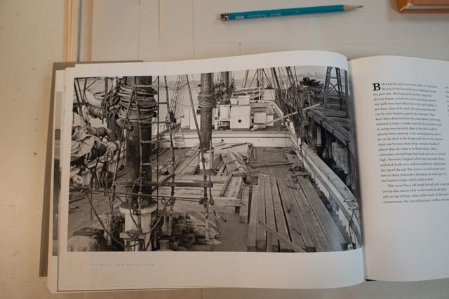
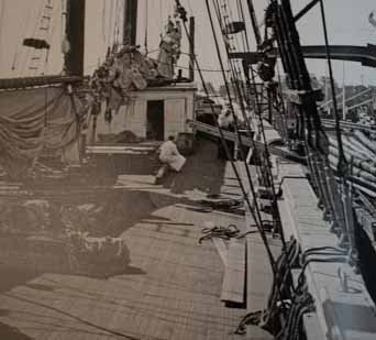
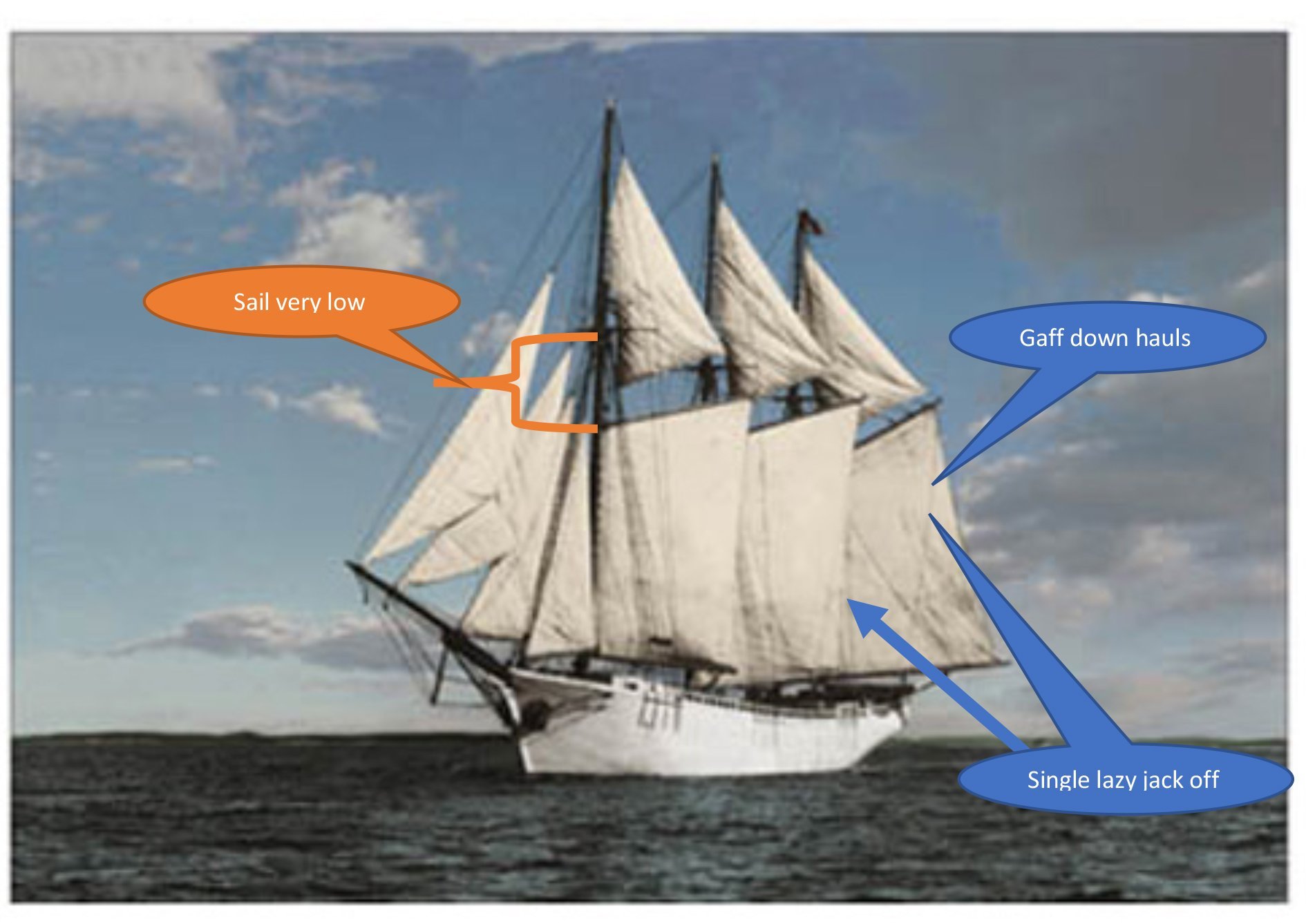
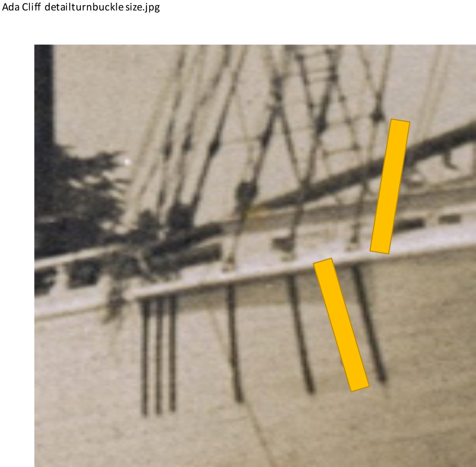
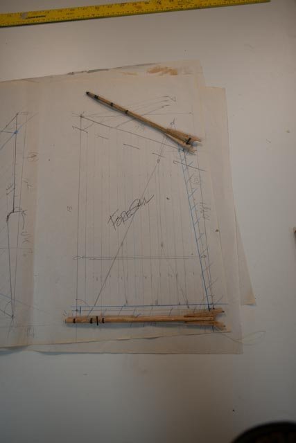
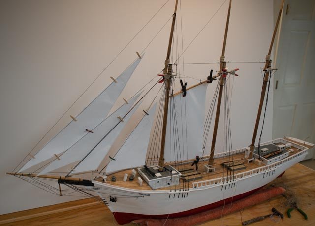
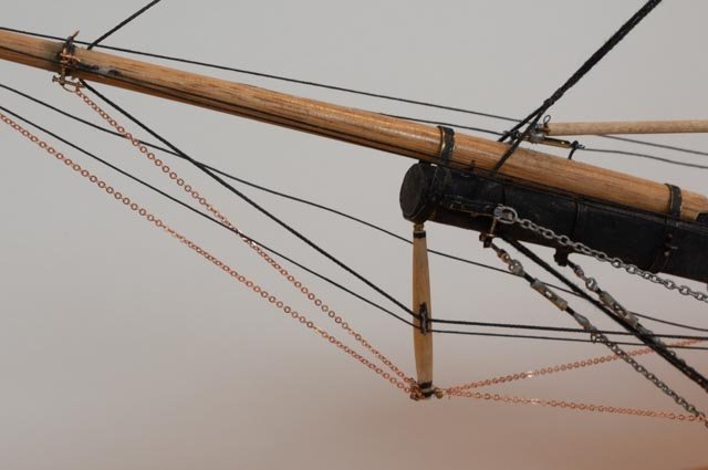
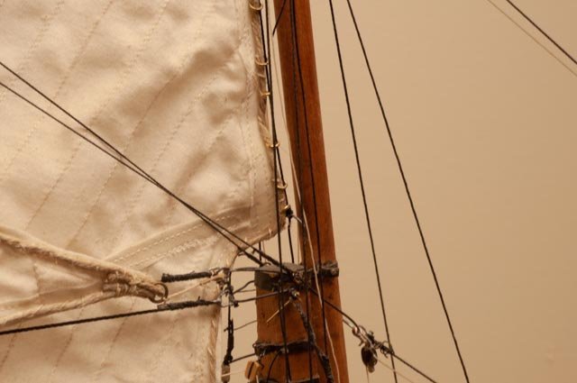
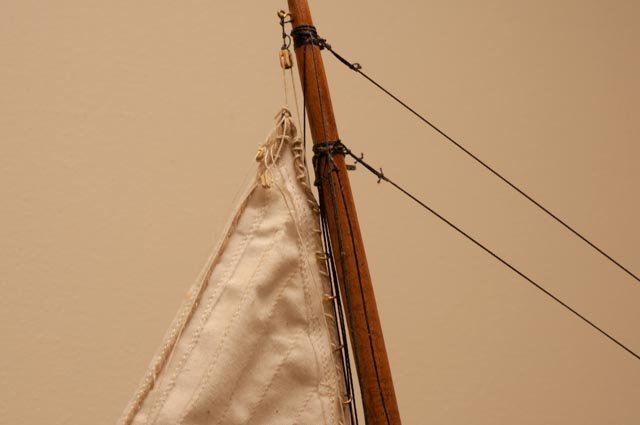
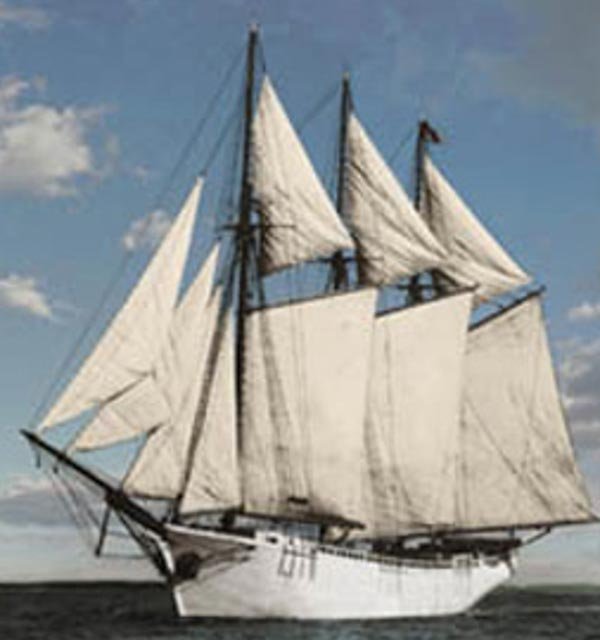
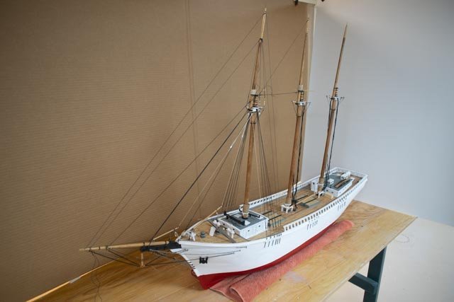
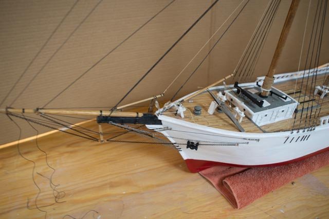
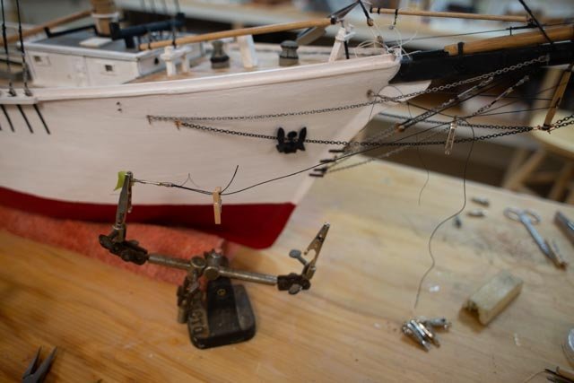
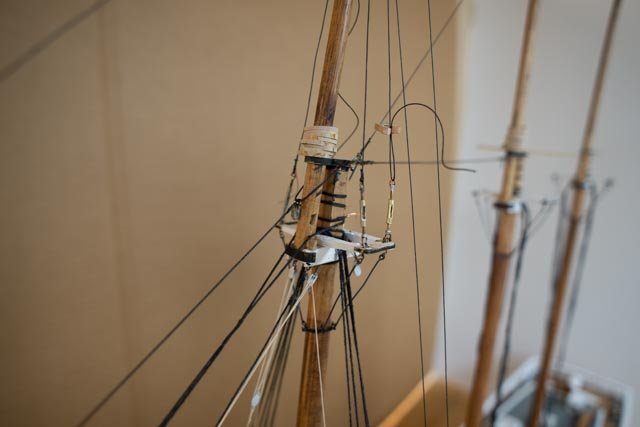
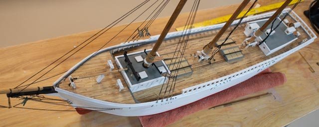
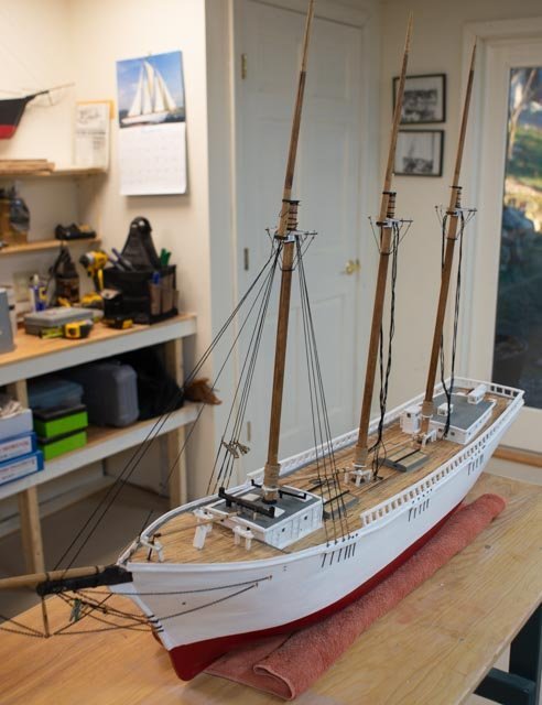
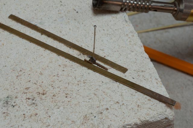
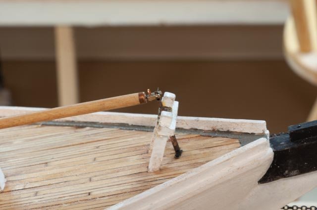
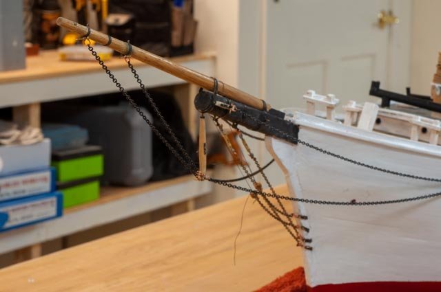
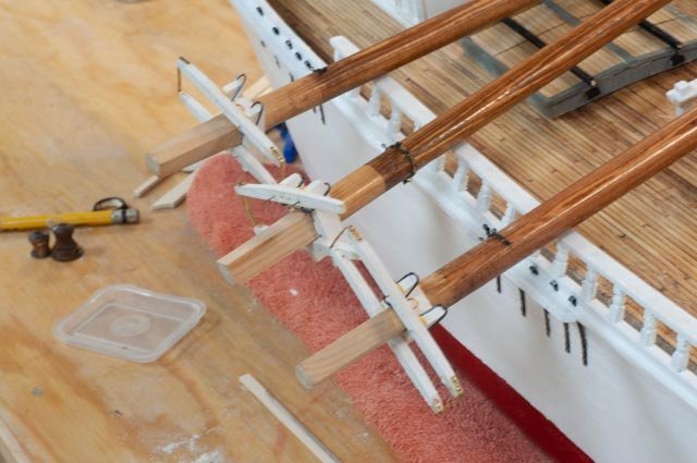
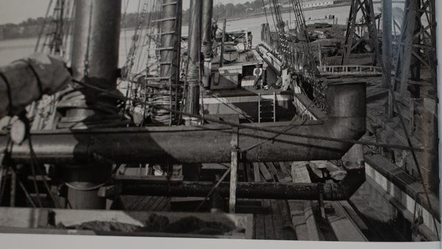
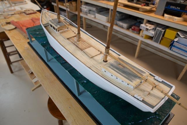
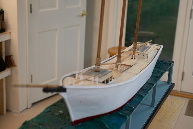
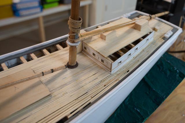
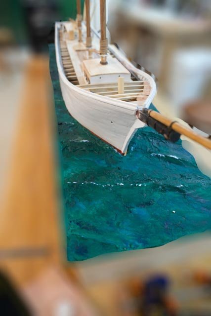
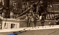
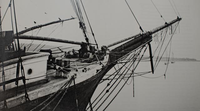
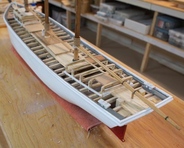
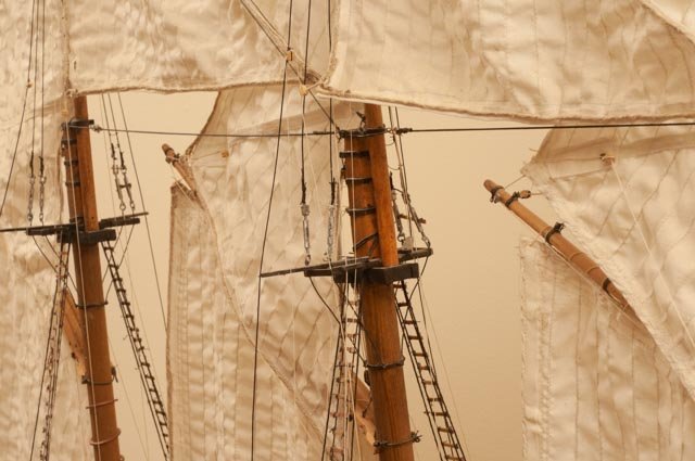
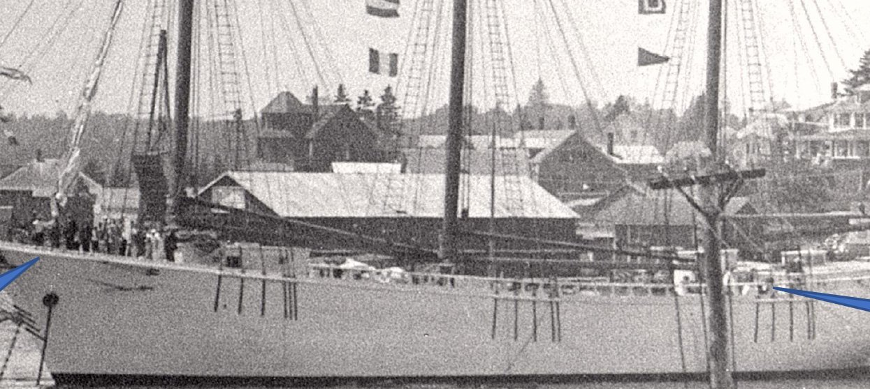
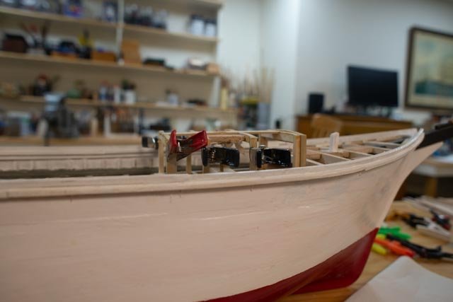
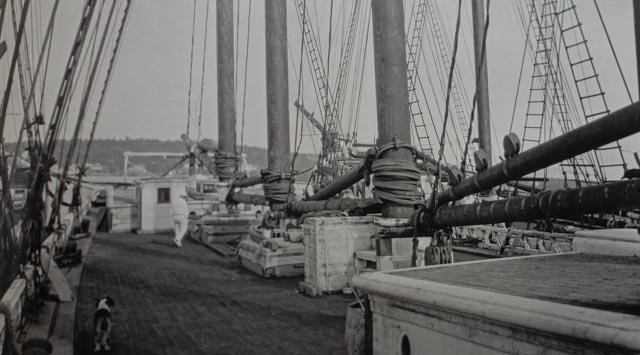
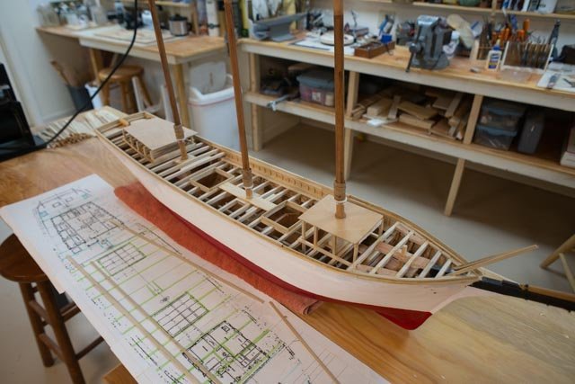
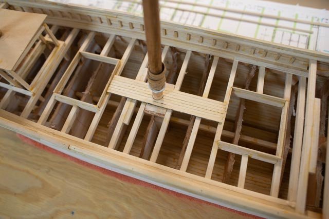
 post 33 Planning the first sails, work on deck I have said my plan is to learn the silk span process as I move forward. As to sail design, my initial plan is to replicate the photo I have shared before and annotate here 288 here we see a few details for rigging. I note items that are different from the reference drawings on Bertha and the Bath schooners. The foresail gaff seems to fly a little lower than the plans indicate. The gaff downhauls are clear, and the lazy jacks seem to be simplified to one drop from the lifts. Most importantly the top sails seen to fly fully above the gaff and thus easier to handle when tacking. Most plans show them hanging below the gaff. 289 this working markup was taken from the cad scaled rigging plans. they seem to compare nicely between the three sources discussed before. Looking then to the actual sizes in the model I have adjusted them down a bit. Finally, I have scaled off the photo and reduced this sail’s height by one inch or about 4 feet. 290. here are the first patterns cut out and fit onto the model. The fore staysail is a bit smaller than the plans as is the jib since there is a self-tacking jib boom that showed in the launch photo. The flying and outer jibs are just the same as the drawings and seem to look ok. I may shorten them just a bit to conform with the others. This is also the view to see that different sizing of standing rigging make sense as to where the big loads lie. Next up here for me is to make the other patterns and then gain some practice with silk span. There is much mystery to this process. I see videos that vary significantly. Some are recommending laminating layers over copy paper with all the markings. Others just use the silkspan itself, paint and mark it. I have no idea where I will end up. I bought the recommended booklet and read it. Now that I need it, I can’t find it…..sound familiar? Related standing rig ac-291 I said earlier I needed to buy some more chain sizes and do a better job with the martingale supports. Here we are in a better size. Ac-292 I feel backing away that this view makes better sense as to where the load is. I have learned through some of my reading that the issue with these schooners that became a limiting factor was the undue loading down to the bob stays. The New England 3,4,5 and 6 masted schooners all shared a common main support system. It started at the aft most mast head and travelled forward through the spring stays. In four masted the spring stay from the main to the foremast were doubled. In all these schooners the jib stay is doubled and runs down and around the bowsprit, which is then grabbed by the chain bob stays. When many of these schooners failed and lost masts, it was the domino effect of the bobstay going and then all masts failing. There are written discussions on the efforts to challenge the design, but all that took place too near the end of sail over steam. I believe today some of the multi masted cruise schooners all have forward stays and stay sails on the multiple masts making the gigantic 30–40-foot boom and gaff fore and aft sails of these beauties not possible. The idea that kept them going as I have read it, was the following. With the spring stays over the large fore and aft sails, that could be raised and lowered with a donkey engine, it was a very small crew that could sail the vessel loaded down with coal, lumber etc. The usual calculation I have read is 2 men per mast plus captain and cook. Thus, Ada Cliff would have had only 8 crew. Merry Christmas
-
Roger thank you for your helpful comments. as to the items you mentioned, I have the liquid flux that is sold with the tix soft solder. I hope that is right. For small pieces I know you are right as to process. My constant problem has been when I use the electric solder gun to get heat into the pieces, I have to touch them with the hot tip. It seems whatever I have done to secure the pieces, even those nice tungsten arms, the small pieces move and the joint fails. Sometimes the tip gets all black and does not seem to transfer heat. i clean and then it works for a few times. I have been told by others I am nuts to use the torch, especially when I am doing such small work. the only advantage for me, the beginner, is with the torch, it is a very quick flash from say three inches away and nothing moves. I agree that the copper shackles clearly get too hot. I believe I am supposed to heat the copper to pull the solder from the brass screw head into itself. I am sure annealed copper 22 gauge vs. a brass machine screw heat up differently. I will carry on and complete I believe about two dozen more. With your inspiration, I will go back to the liquid flux with the tix solder and electric tip. If I can figure out how to avoid movement maybe I can be OK. thanks again for looking in. Merry Christmas too
-
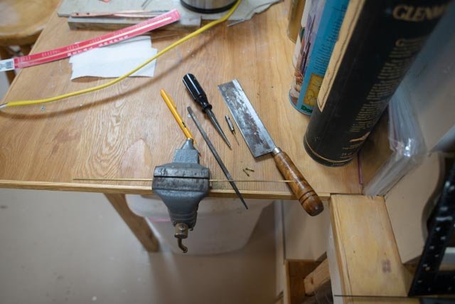
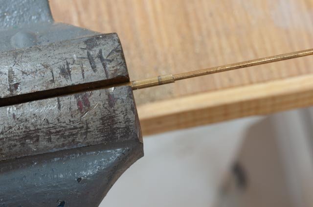
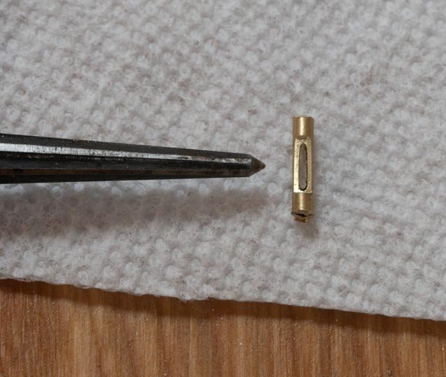
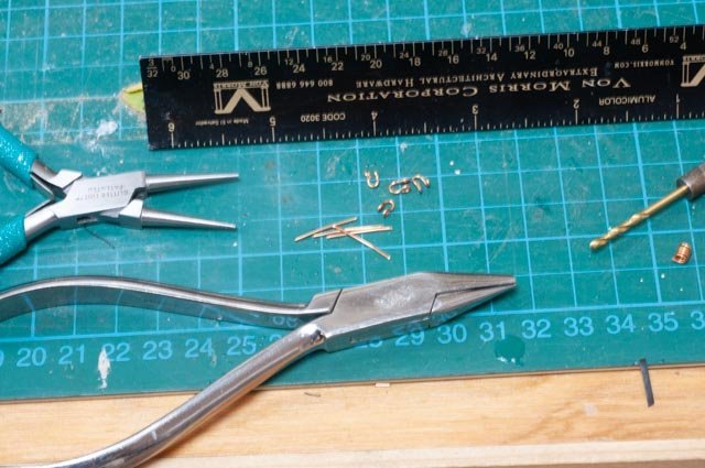
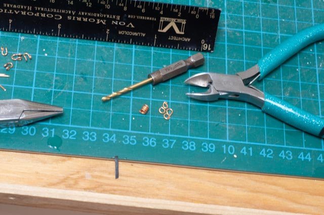
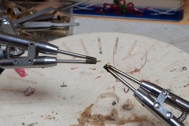
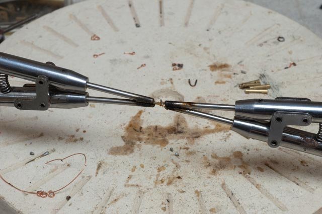
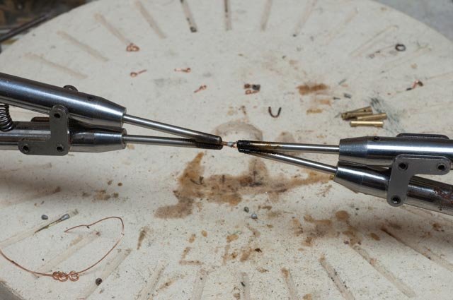
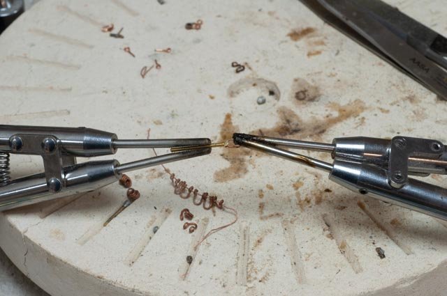
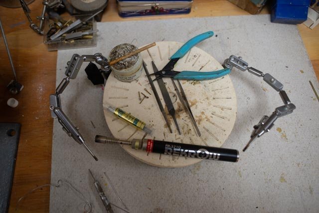
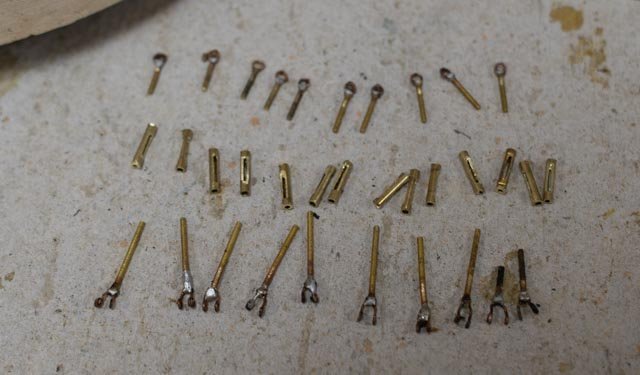
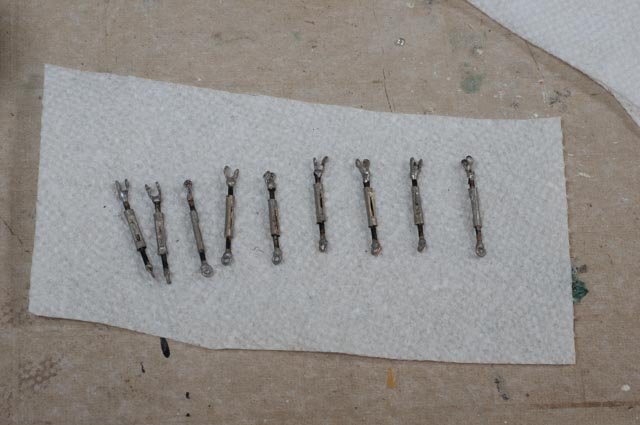
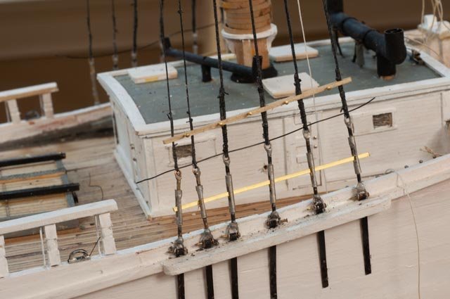
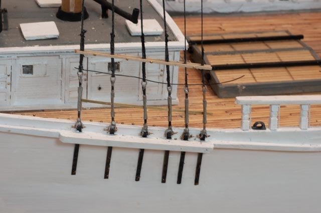
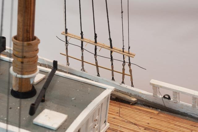
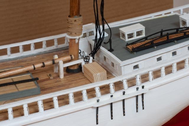
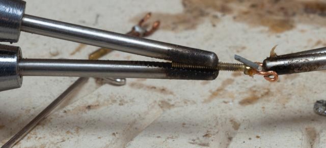
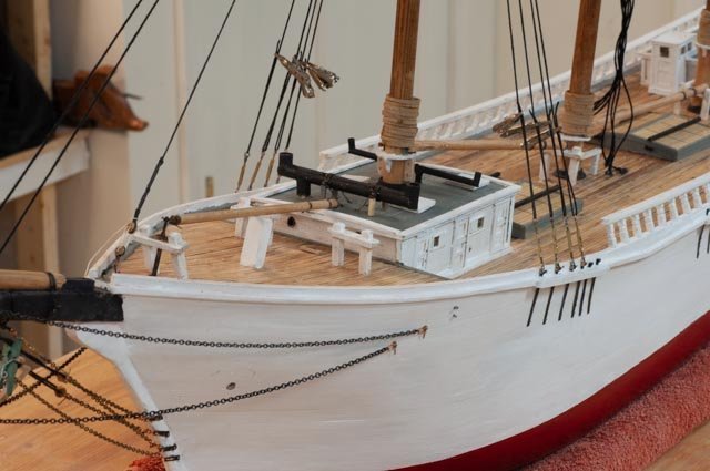
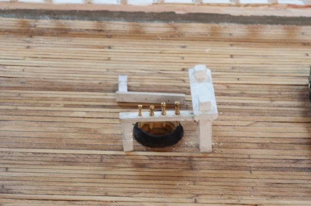
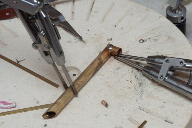
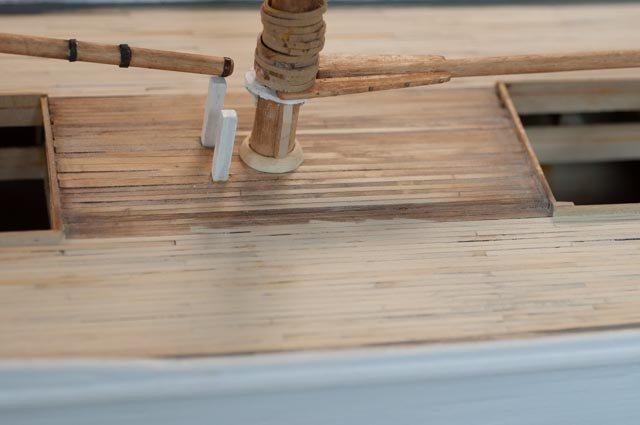
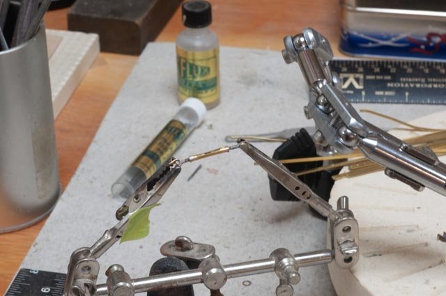
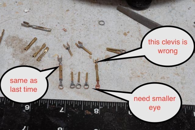
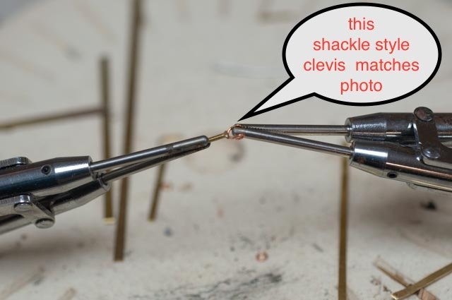
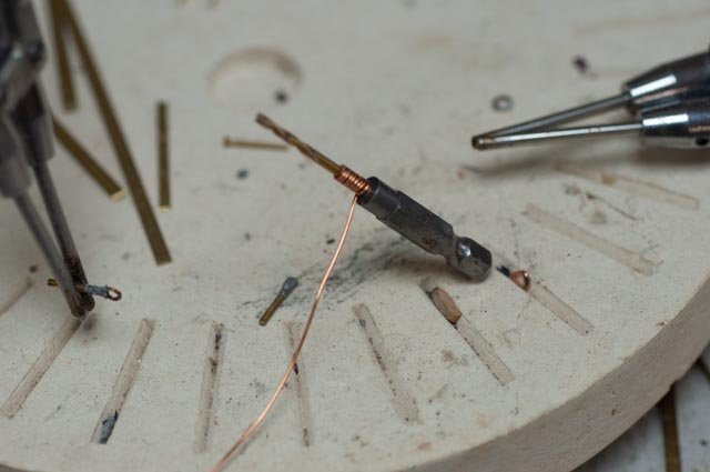
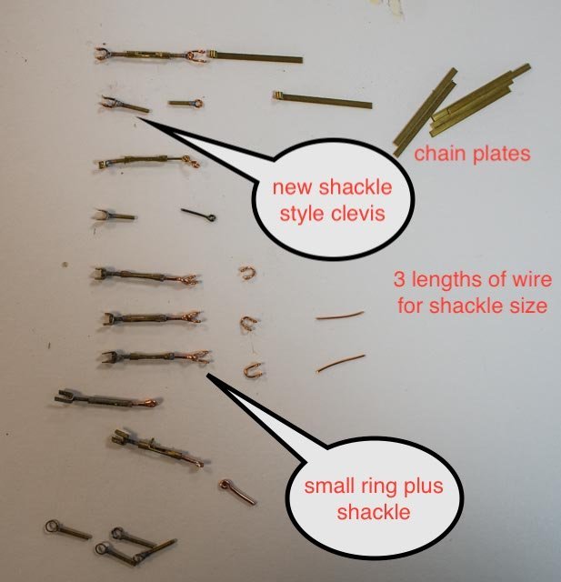
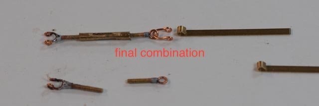
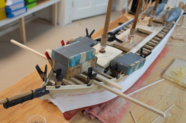
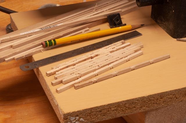
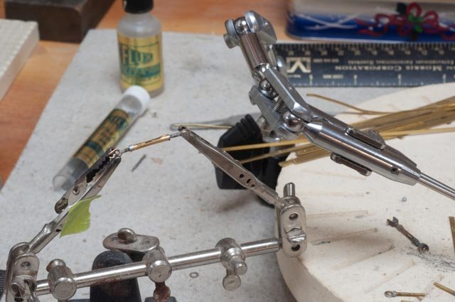
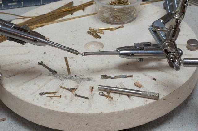
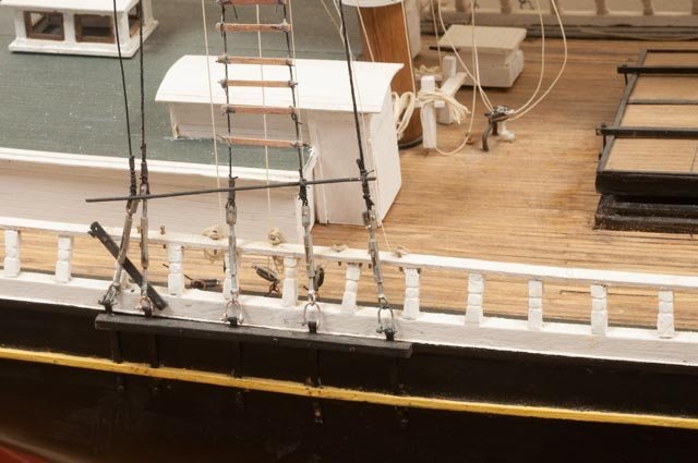
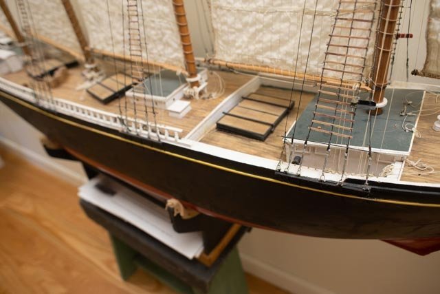
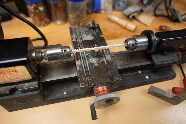
Post 32 Turnbuckles I offer here here is a series of photos showing the sequence of production I used to make several dozen turnbuckles. This process ends with an obvious handmade product. I am not a metal worker, nor am I able to use my inherited lathe/mill to make more of these pieces. In a machine one can reproduce identical elements. Enough of that…. Following views from many schooners , I found a common element. On the bottom there is a clevis or shackle that connects to the chain plate. On those with a ring and shackle ,the ring is too small for me to model. Therefore, I chose to make the shackle attach to the “shaft”. I chuckle because after several searches I have never found neither good nor consistent names for the parts of a turnbuckle. In an earlier post I showed the evolution from my turnbuckles on Charles Notman to my turnbuckles here. There are three pieces, sub-assemblies, to make up the turnbuckle, the center barrel [ also called sleave or body], the bottom ring/clevis and the top ring [ eye] . The barrel : 273 This process is straight forward. In this photo one can see all the tools set up. I take a 5/32nd” brass tube [ 1/16TH” ID] and mark it off with a pencil the center section to be filed. I then fill it with a 1/16th” rod for support and place it on the edge of a small vise to help guide a square file. I file down one side then turn it over and repeat the other side. I then use the center punch to scrape out the slots. 274. Here we are set in a small vise for filing. 275. Here we are after scraping out the slot. The clevis and ring ends For the clevis end, I settled on using 22 gauge annealed copper, cut into 5/8th” lengths for bending the shackle. I then use number 80 brass hex head machine screws for the shaft. For the ring [top] end, used the 22 gauge copper wrapped around a 5/64th” drill bit and then cut off rings. I then used 80 brass flat head machine screws for the shaft. 276 first we need to make the shackles. I measure the 5/8th“ length and then hand make them. 277 second we make the rings. Wrapping around the drill then cutting off the rings. 278 third we take the machine screws, here are flat head, put them in the vise and with a triangle file, enlarge the groove and use a small flat file to trim the sides. For the shackle end, I used hex head screws and filed them the same way. Soldering 279 Forth we need to solder the shackle or ring to the machine screw shafts. Note the copper wire with loose rings as they have first been pickled. I find pickling the easy way to prepare them, since they are too tiny to clean effectively. In the photo, the solder is in place on a ring end. 280 the ring end after solder. The next rings are sitting after the pickling. 281 here a shackle has been soldered and the next batch are waiting. 282 here is the combination of tools used in the process. Note I use normal flux and for these tiny connections the TIX soft solder. The pencil torch works well. I tried and tried with an electric gun and the liquid flux but found this process for me works best. This is the first project where I have forced myself to try and try again and get to where, ugly as it maybe, it is soldered. 283 after a while I have a batch of about 8. All units need filing to clean up the over solder. The soft shackle will move around, so until these are being set up against the chain plates it is better not to work them too much. Similarly, the top rings get buried in a splice so not too many worries there. Finishing Next up they are cleaned up, trimmed, and assembled. The ends are crimped into the tubes. Then we go for paint. They are three different materials, and we are trying to get galvanized and black grease on the threads. 284 these have been assembled and painted. They are running 1 1/8th in length. What I found running through pictures is the newer schooners seemed to get smaller turnbuckles. I also found closed bodies show up on areas like cap shrouds on the foremast. I can see in the Ada Cliff launch photos clearly enough to gauge the length and to note the open body design. I use aluminum paint to replicate galvanized metal and black for the greased threads. 285 here is the first batch installed starboard on the foremast. Crimped as they are, I can turn them and insert the small brass bar. I need to snip off the brass nails, retouch them with paint as they too would have been galvanized. The black rod is soft copper, and I need to either find a stiffer alternative or get it as straight as I can. Hopefully each batch gets better. We’ll see. 286 here is the batch on the port side. 287 here is the view looking across the deck at the inside of the shrouds. Since my goal is to replicate how things fit together and where appropriate how they work, I am OK with the hand made approach to things like shackles and turnbuckles. For any RC vessels, I have and will again resort to the store bought version . Threading rod and then thinking about left hand threads is way over my head. Also the load on the sailing version requires more strength that this static model. all for now
-
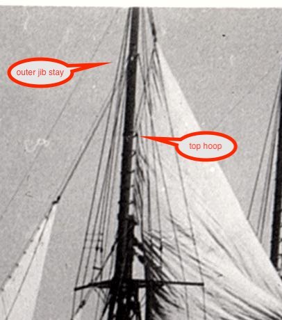
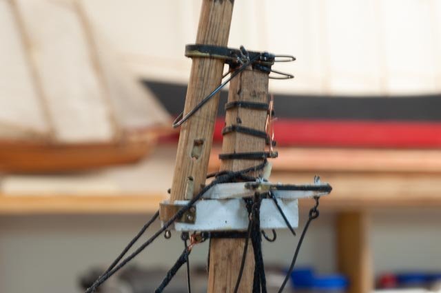
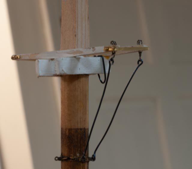
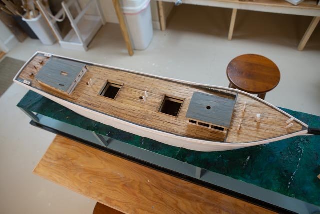
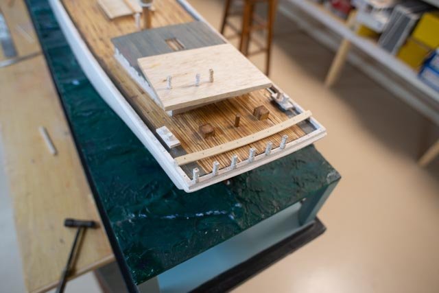
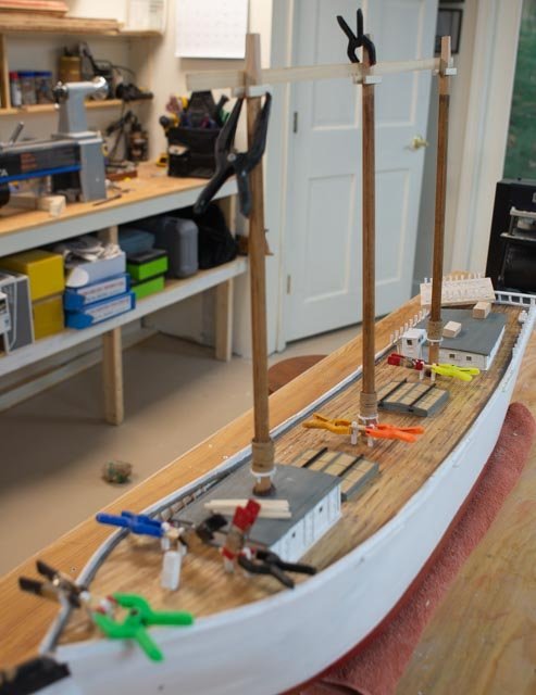
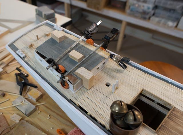
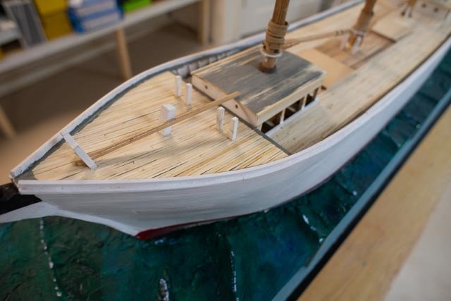
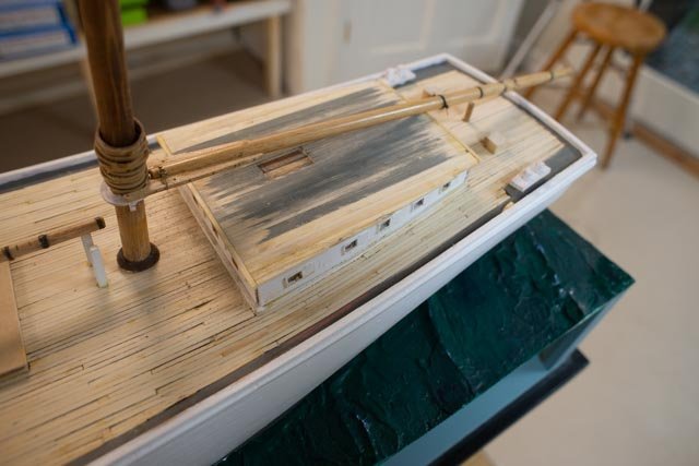
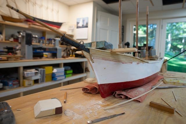
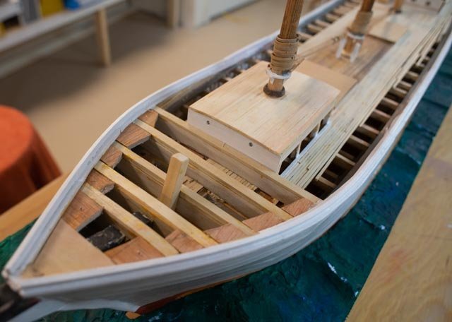
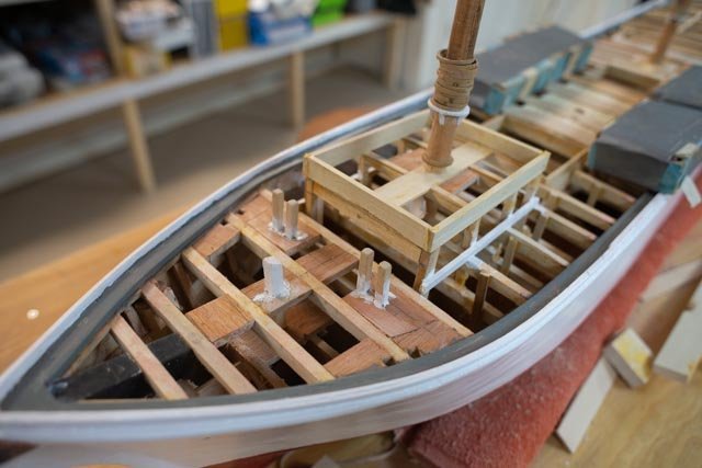
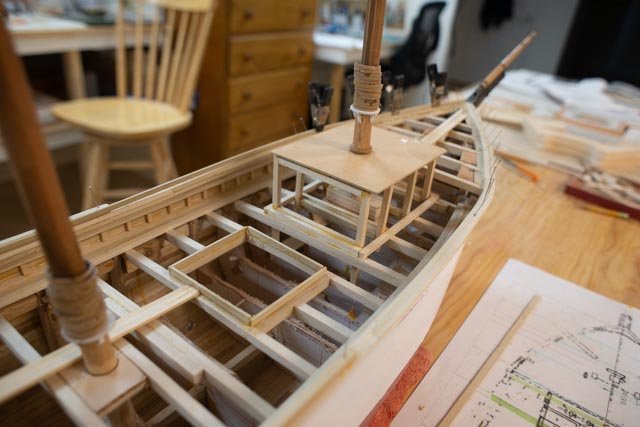
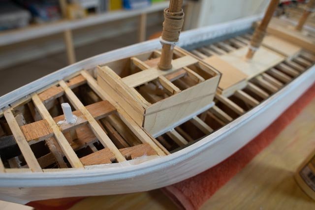
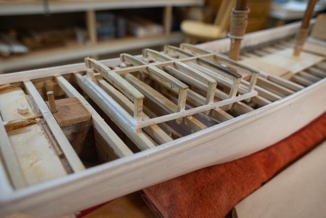
post 31 My first rigging questions. I find that each time I start to rig a schooner that I have much more to learn. Some of it is just adjusting details between vessels, some is relative to all schooners, and some is just how does one model it. My priority is to understand how to sail the vessel and try to model that. This priority overrides other goals. So first up is how to correctly represent the fore top mast. When I studied the designs from Bath, including Charles Notman and the Bertha Downs, I found a few details that made sense. My first issue is the outer jib stay hits the fore topmast about 2/3 the way up. That was no issue on the Bath schooners based on Douglas Lee research, as they used jack stays for the top sails 264 a and B show bottom and top of the jack stay on my model of Charles Notman. the sloppy sails were because she was a true RC schooner. 265 a and b repeat of photo ac 24 to review what we are looking to achieve overall, and b is the blow up that highlights the hoops are used and they stop below the outer jib stay. The sail “flys” above that and drifts several feet away from the top mast. 266 here I have hung some cardboard to see if that helps in studying and photographing the rigging. I obviously need to get more white cardboard. 267. the foremast …My goal is a to complete all rigging on the foremast as I continue with work on deck. The topping lifts and sheets for the jib and foresail are the first running rigging in place. 268 shows something I need to learn. The sails need to be out. But what is going to hold them out? I have the tools extending for the two small booms right now, but I need to find a solution. In my other rc models I tilted the whole boat in a strap cradle and gravity does the work. As of now that won’t work here when set in the water base as there is not very much of a heel in this rig. 269. work aft is plugging along. Here there is a blank box representing what I think I will add for a small engine to run the pumps. I will talk about that when I collect a few more photos and then build something. The pump details come for the bath technical drawings that do not show an engine. 270 Several photos show that by the 1920’s small gasoline pumps were being used .As much as these coal schooners leaked ,there is no way the small crew pumped by manually spinning the wheel. I do not believe what read that he traveler line from forward could hook up to the pumps. that is a bull in a china shop. more important they likely needed to run at the same time. 271. here is some fun work as I add more and more stays. Here I am splicing another turnbuckle for the inner jibboom guy. As I study more photos, I am convinced that there was more and more galvanized components. I have started touching up with paint to get that look. 272. here is some progress as the top masts are now set Production of turnbuckles is picking up. I will show that process next time. I found enough evidence to proceed with painting blocks white. all for now
-
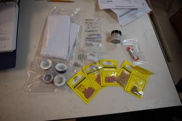
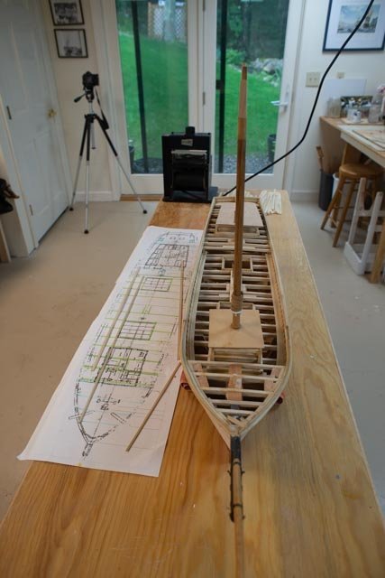
This past week was full of fall outside work and little modeling progress. I do have a photo of the fun procurement items that will get me far into the rigging process. As i commented I like using the Bluejacket schooner fittings and blocks. New to my building since the diorama of Ernestina is my migration from annealed copper to annealed steel for many of the small hooks, eyes and other fittings that are in any tension. I still like the feel of the copper for shackles . Finally we have the new silk span for my first attempt as sails. Here we go. From expo I have a couple of sizes of chain, and with one I will fix the wrong one installed on the Martingale. I have read that the topsail sheets were sheeted with chain where they go over the jump stays and will try to add that detail this time as well. Also apparent in the new pile is the choice of belaying pins. I have looked at wooden and brass and have chosen to go with the brass 5/16" as they seem to look more like a 20th century items. Still a few competing projects so it won't be quick. jon
-
Allan you are right! I hate to admit what the cost was on the materials I share in the next post. As to turnbuckles I have found that those on line are typically a barrel type. In the photos I have found a few samples of barrels on places like the jib stays . That would mean 6 out of maybe 60. What I see in the launch photo of Ada however, confirms the open yoke style even in those locations. Thus filling away is the only way I know to get there. I will group some photos for a post in a few weeks. thanks for you shared thoughts. It truly is a constant learning process. jon
-
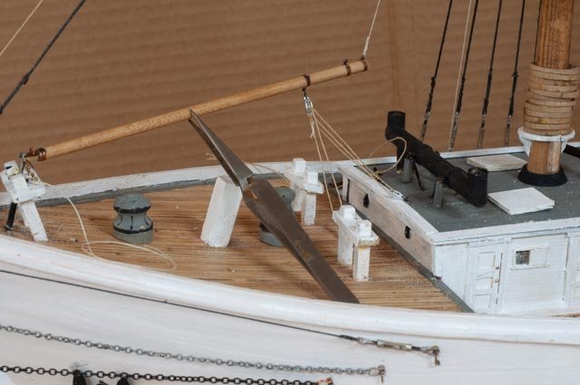
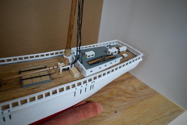
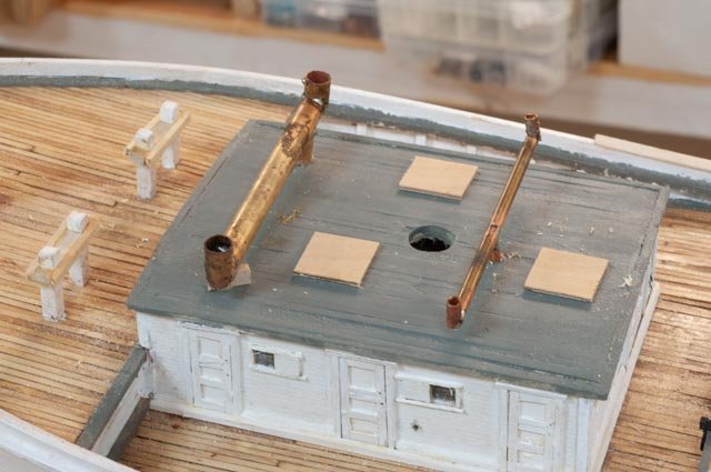
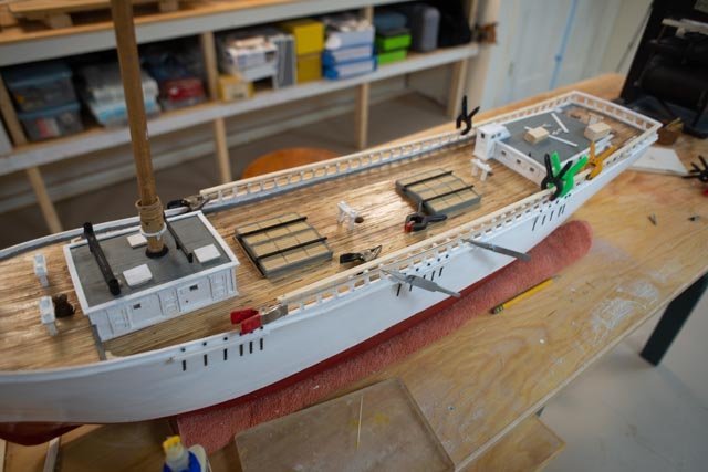
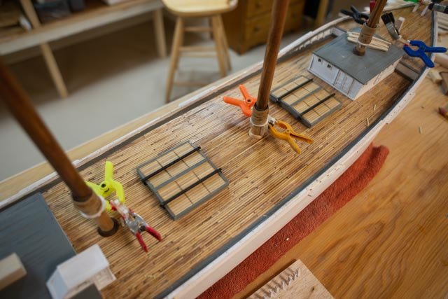
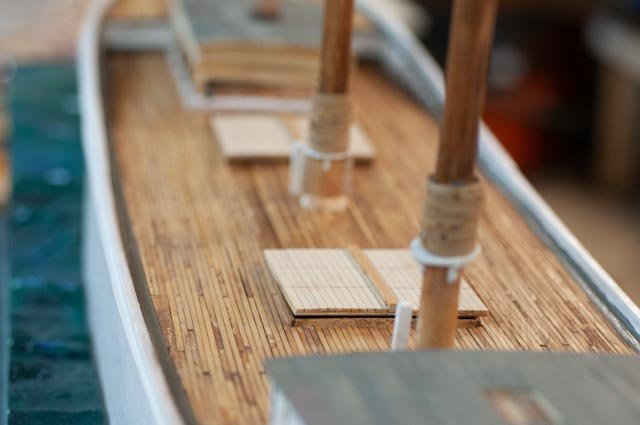
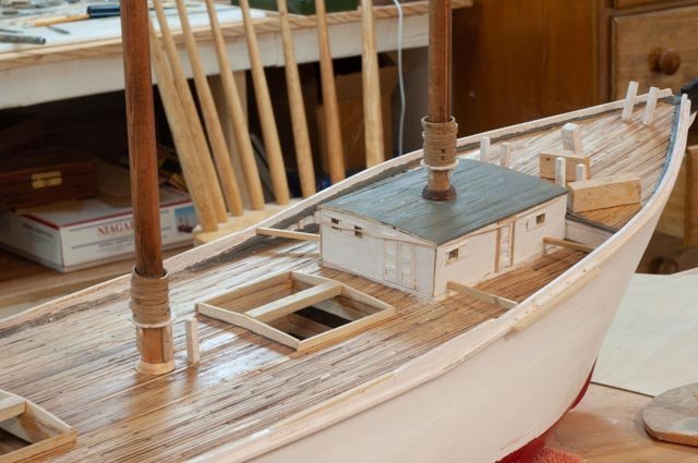
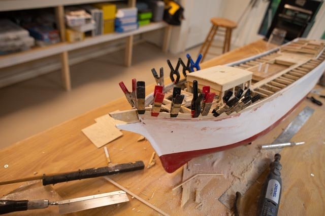
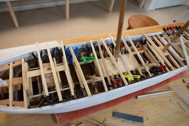
Post 30 Slow transition deck to rigging I write this paragraph to record the slow shift, as I am probably halfway through the deck work. That is other than clean up and touch up paint that never ends. I am moving into the rigging partly as much of that work is done on the side and brought to the schooner only for installation. Much of what I find in this stage is I get to try something, and if like the chain on the Martingale I mentioned above, I don’t like it or it is just wrong, I get to do it again. I have a few orders out for needed material to do the rigging. Unlike the master builders we all love to follow, I do not make everything. Early 20th Century navy anchors, cast iron on deck water pumps, and the like I get castings. For blocks I love to use Maine made Bluejacket blocks on my Maine schooners. I am also getting from them my first silk span. Including the last few posts, I am working away here through this transition. A few more tidbits and overview. 257. After many tries, I final got to a process to make a series of turn buckles. My first ones remain a bit crude, but hopefully as I work through the 50 odd units, they will get better. I am a full amateur when it comes to solder, but I insist on learning the trade. To get the annealed copper wire to take, I chose to make up 10 shackles and pickle them. I also pickled about ten wire rings. With that added step and the freshly filed cap screw slots, I was able, using a butane torch, to “flash off” and make the joint. I finally figured to use a flux paste and that helped hold the little cut length of solder. The electric iron and liquid flux are both back on the shelf for now as I just could not get it to work. 258 here we see I followed several pictures and made up the supports for the boiler stack. They will be part of the next round of touch up painting that this photo shows is really needed. The thin brass was blackened, but all the working after it will also needs touch up. I find the lamp black paint works well for this purpose. Also, in this view we see I finally found enough evidence that the mast wedges were not wood wedges with canvas boots as on older vessels. A few photos showed there were four quartered iron and bolted. Thus, I filed them down [ they are maple] some and added lamp black to simulate the iron. 259. backing off we see the transition beginning forward. The shrouds are clamped off. I need some aluminum paint to get the galvanized look on the turnbuckles before I make them fast. This transition also means the lower masts are there to stay. 260 here we see in the transition there is still much to do aft. I have the deck house skylights roughed out. next up will be to add bars and iron rods to keep the lines from fowling. There is another stove pipe, then a gangway, yawl boats etc. much to do!!! 261. looking down we see a clean deck for the last time. Soon we need to get all though pins in place and be sure we have enough. I always find there are more lines than pins and expect no less of an issue here. Example all photos confirm lazy jacks. They go to fife rail on a fishing schooner. There are not enough fife rails for all those pins shown in any photos. 262. finally we see the tops taking shape. I am working along getting the top masts ready. I need this step more to complete the sizing drawings for the sails. More on that and rigging line issues later. All for now
-
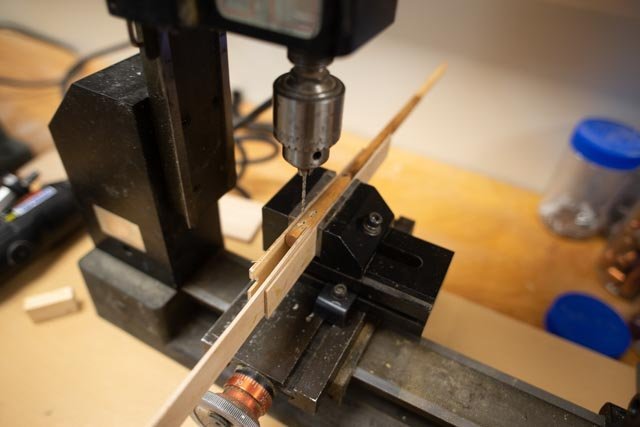
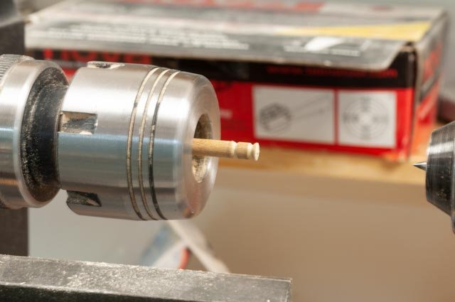
Here are a few more photos as I move through this long middle section 251. I am determined through this build to develop some soldering skills that have previously limited many opportunities. Here is probably my fourth attempt at this tiny fitting, the fore staysail gooseneck fitting. 252. celebration …it worked. It’s Not so elegant, but functionally represents the details out of the research books. 253. here all together we have the fore stay with lashing and the complete gooseneck assembly. 254. having learned the benefit of using the mill for drilling slots, we are off drilling slots for the fid and sheave in the top masts. 255. here is my shortcut to make little wooden sheaves for the top masts. 256. here we have the fore top mast resting in place with the fid and sheave in place. Both the forestay and jib stay are in place as well. Happy Thanksgiving
-
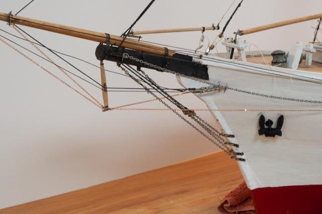
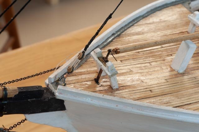
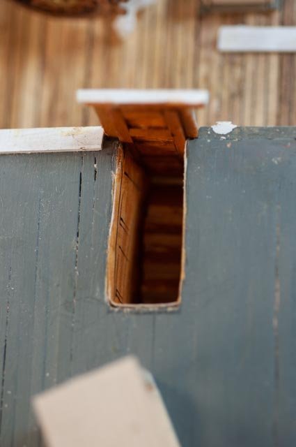
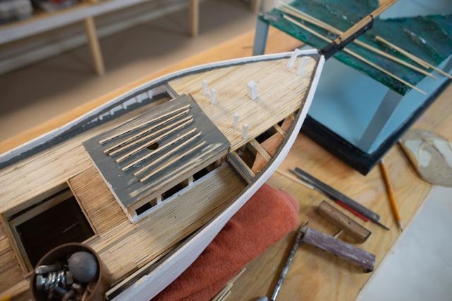
Not a progress posting just a few photos. 248. just in case one does not know what happens if the phone rings or some other disturbance arises, and you forget there are pieces in the blackening solution. If you leave them overnight they become toast. The top ones toast the bottom rebuilt. 249a here I had some fun. I cut away the cabin to make the aft companionway. 249b. In the second shot we realize once I build the enclosure, there will be little to show, but it will be fun to know about. One of those little surprises 250 Here I started rigging by stringing the chains on the bowsprit. From the photos I believe these chains were galvanized. Like the two turnbuckles included I need to get some metallic paints to replicate the galvanized finish. I also note the lower chains at the tip of the martingale should be a bit smaller. cheers
-
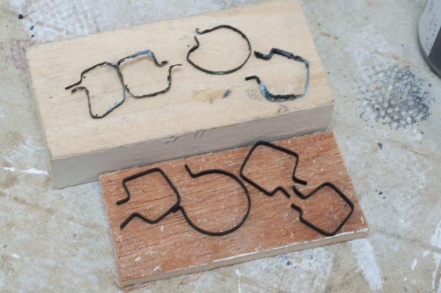
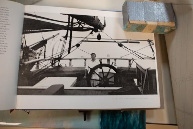
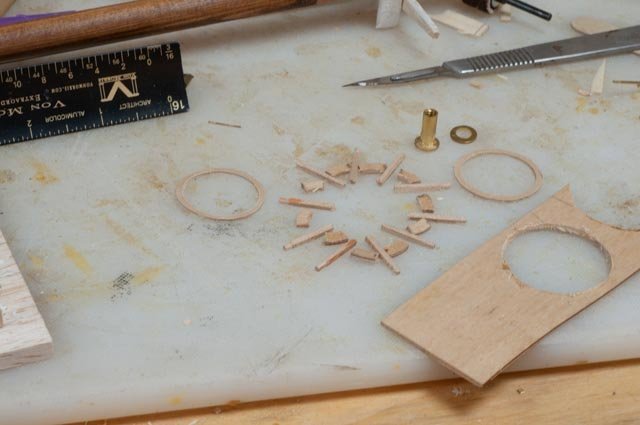
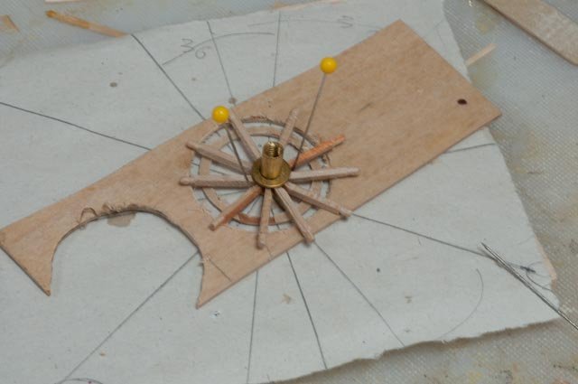
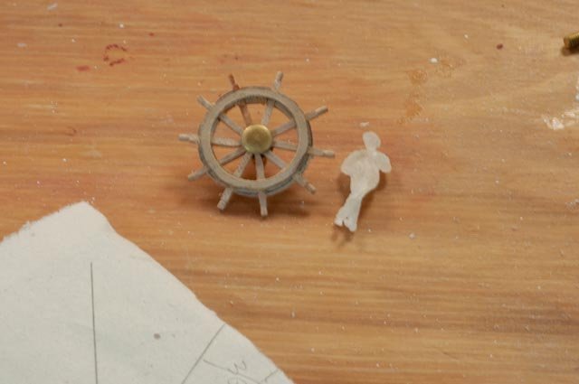
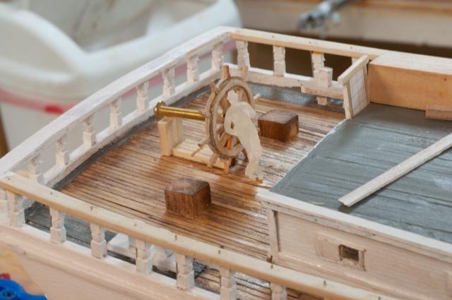
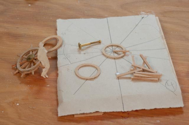
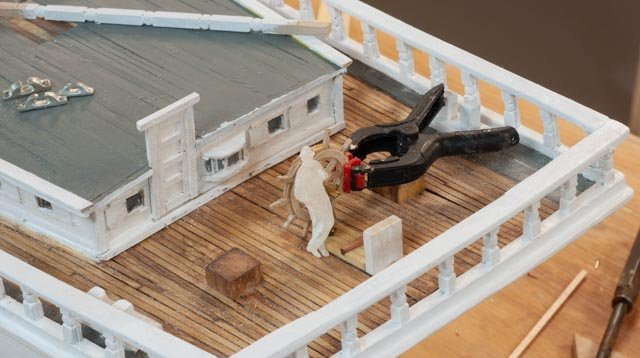
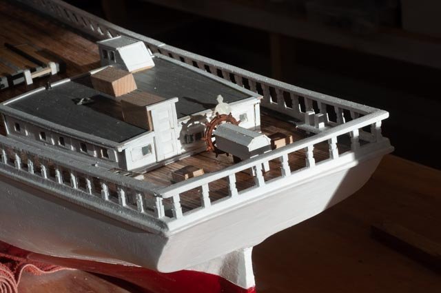
Post 29 The helm Building the helm is always fun. One of these days I hope to do the gears, but I have much to learn before trying that. Anyway, I needed to find some photos to see what I would try to do. 238. here we see the helm on Zebedee Cliff. It was built four years later but I believe the style is fine. I am not sure how tall the 1933 tourist in the photo was, so I am going for about 5-foot outer diameter. 239. I have used this method before and though crude it seems to work for me. I use a Forstner Drill Bit to cut inside holes in birch plywood. I use 1/16” for the center and 2 each 1/32” for the rims. The inside gets cut into segments to go either side of the spokes. 240 here we are set up to glue the spokes on top of a template for the 36 degrees per spoke. I use maple for the spokes as they are turned. 241. tada….oops I think we are a bit too big. Well, this was good practice anyway. 242 just for fun here is the too big wheel on board…..no go 243 back to the drawing board we used a ¾” bit and went again. 244 here we are in glue up and I think we may be ok this time. Below lying on the deck, we see the blocking and brake. I used different colors stain, so the pieces make sense. Just a few bolts and a brake slide plate and we are done. On the roof my limited supply of chocks is resting. According to the details I have found all but the forward chocks need to be closed. 245. One of my joys is entering the shop in early morning in winter. The leaves are mostly down, and the winter low morning sun streams into the shop. Here the helm is in place. A few little handles and we are done. Other work 246. Just an update I am working on the mast tops. Here the futtocks shrouds are made up based on details from booth Douglas lee at Maine maritime and the anatomy of Bertha book. I love it when I find two sources that agree. I need to adjust the stain as the mast tops are all light stain and the darker oiled finish that should be below these shrouds. 247. here I had a little fun and wasted a pin rail. I went to my supply of pins and found I have none at 5/16” which is the size I need. Here are 4 different designs of what is out there in a size for 1:24 left over. I need 100 and am in the market. All for now
-
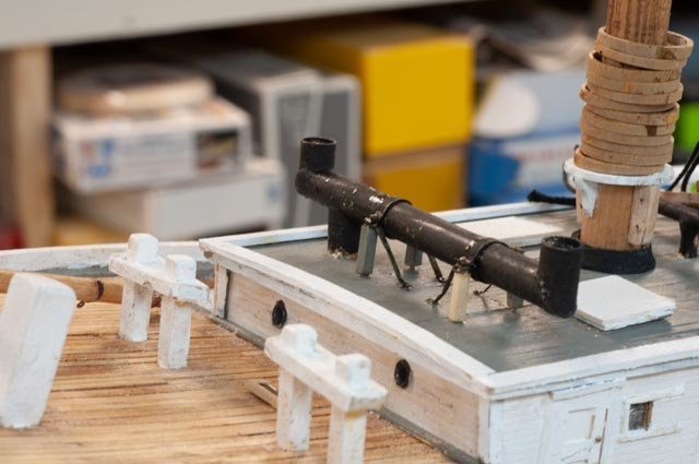
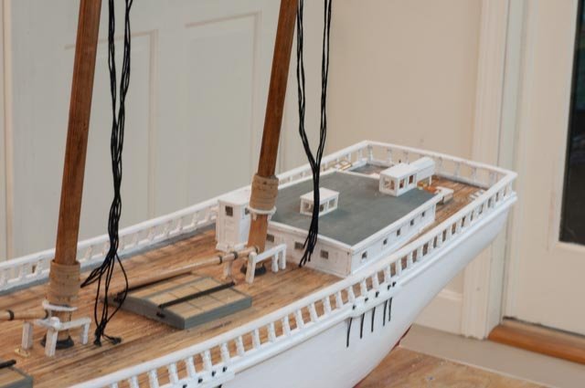
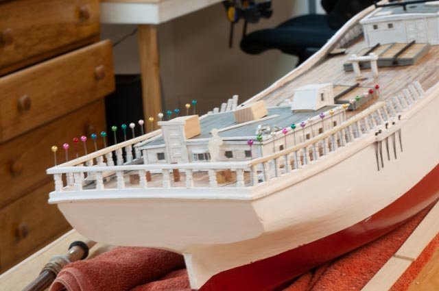
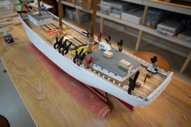
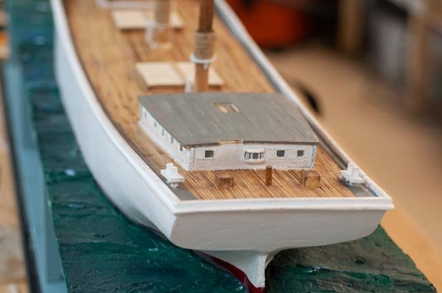
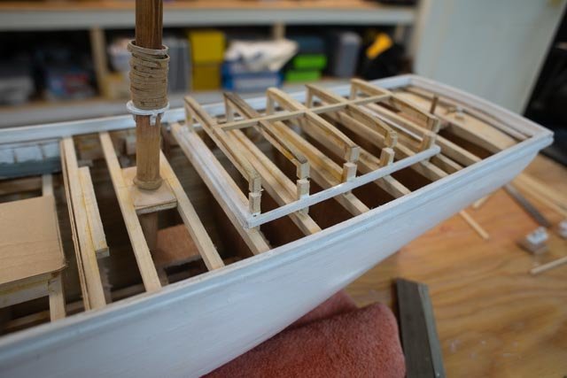
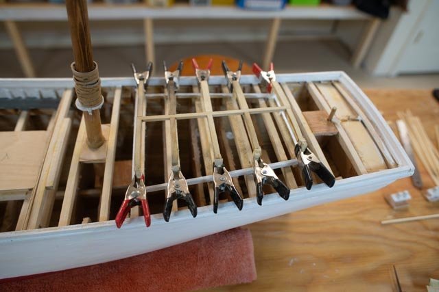
Post 28 Fly rails are installed and helm and top works begun There is less time to focus during fall a Maine clean up, but some progress continues. I have the fly rails installed now and have started preparing the lower mast shrouds and cross tree assemblies as well as continued with other on deck work. 231 here I am in my truly amateur area of soldering the boiler stack. 232 here we are on in place on the fore cabin. The Boiler was forward of the mast and ran the steam engine to hoist sails pump water, raise the anchors etc. There is lots of conflicting information regarding the ending of steam jockey engine and introduction of smaller gasoline engines. I took that the larger schooner built at the same yard 4 years later clearly included the steam flue as justification to assume the slightly smaller schooner had the same technology in 1917. The smaller flue aft of the mast is the galley stove. 233 here we have the pins going in for what is clearly shown on both sets of anatomy drawings. I say this carefully because they are labeled compression rods in one book. As a retired building engineer, I question that label. The wood stanchion was plenty strong resisting any downward forces…. compression. The fly rails contain all the tie offs for all the running rigging. Many of those lines would have tried to lift the rails, thus these rods were from that perspective in tension. The connections of the turned wood stanchions would not have been strong in upward resistance…regardless we move on. Please take note that the colorful pin heads are not xmas decorations. I just wanted to use them up in this effort. 234 here the rest of the fly rails are going on. 235 here we are all painted. Work is beginning on the helm. as well. 236. here again the fly rails in place giving clearer identity to our subject. 237. here I have started building out the cross trees and iron word at the mast tops. I am working on the rigging table making up shrouds as well so they will be ready when we complete the deck work All for now
-
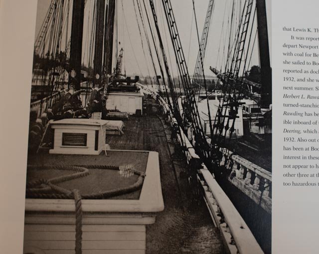
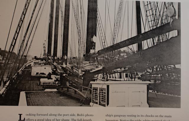
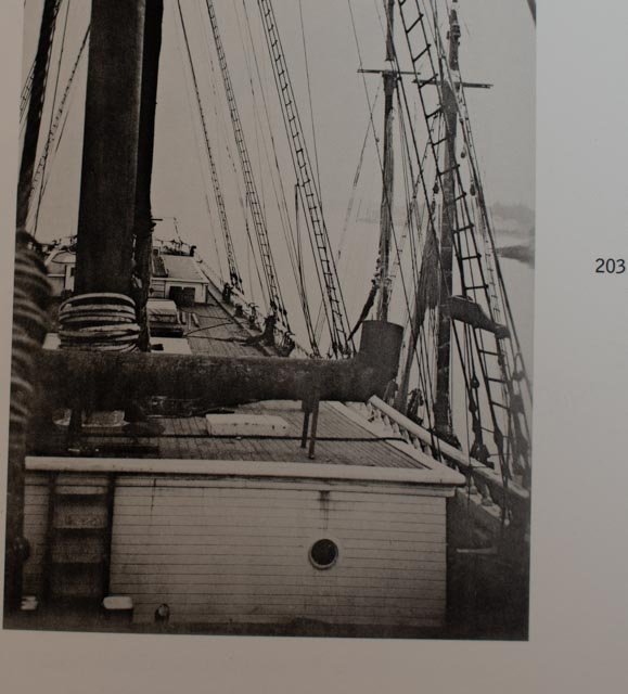
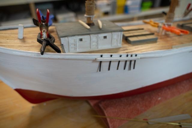
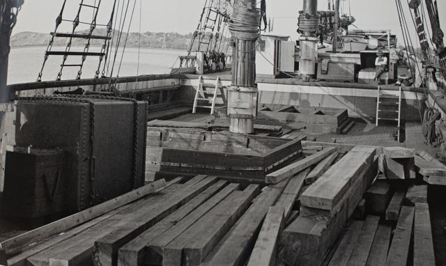
Post 27 Progress on deck There are many interruptions these days as fall is in full swing and we need to get ready for winter. No rest in site. Regardless we plod along. Before showing a little progress I want to describe the basis I have chosen in making decisions about what goes where on deck. I take us back to the Fly rails book mentioned before where several Schooners rested in Boothbay Harbor in the mid 1930’s and were photographed. A key one was the Zebedee D Cliff, sort of a grandson of Ada Cliff ,our subject. After the Yard became the Eastern Ship Company they built 4 each 4 masted schooners. The last and most famous, here abouts anyway, was the Zebedee D Cliff. She was the last one launched. My point is that she was built in the same yard only a few years later. Therefore, the views of the deck give us a good potential of seeing what might have been on deck of Ada. I start with three photos from the book…. 221 starboard aft looking forward: Note the treatment of the deck house, the long rail leaning in and the bollards. It looks as though those fore cabin doors slide…oh well I copied another view where they are Dutch doors. 222 port aft looking forward …just more details like the galley and crew quarter hatches on the fore cabin, gang way, white large blocks, etc. 223 forward deck looking aft …at the fore cabin. Note the large exhaust for the boiler forward of the mast, the port hole etc. this schooner had only one deck level exposed. The tip-off is the fly rail going all the way forward. 224 This view is not the same schooner but a lot more items are here to consider. The galley stove pipe, also, for information, note the shrouds were removed on the dock side to promote loading A little progress 225. I did not show this view last time, but thought is worthwhile to document the nice clean empty deck. 226 I also left out this photo showing the assembly line for the balustrades. I make roughly 8 at a time. After a single coat of white they get pinned into place. I then drill through the cap rail into the balustrade and glue a small pin. 227 here we are lining up the cross trees at the mast heads. 228. I build the hatches and am working on the bitts. Most photos show not fife rails. I am still working on that because there are many lines and normally 12 of them tie off there. More to think about. I need one for the pump regardless. 229 I chuckled when I read the angle of the balustrades is 14 degrees. Forgive me for using a 15-degree pin when cutting them. 230. here we have a milestone. I have made and blackened the chain plates and they, the first metal work, are now going in. All for now
-
Thanks Jim from here on in is the fun stuff.
-
Thanks Keith yes these big schooners are quite substantial. I just went back into the detailing done with photos in the late 1930’s. There are several fun details I hope to include to show how the small crews sailed these beauties cheers
-
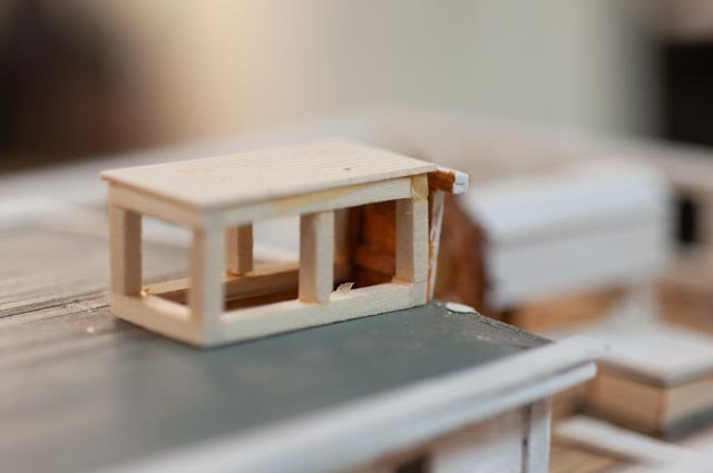
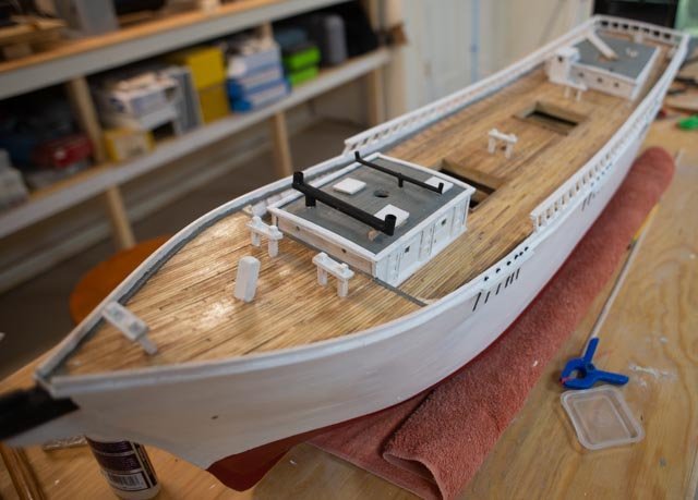
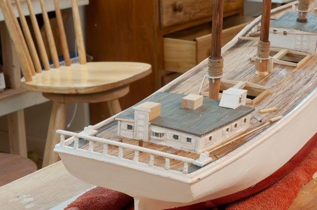
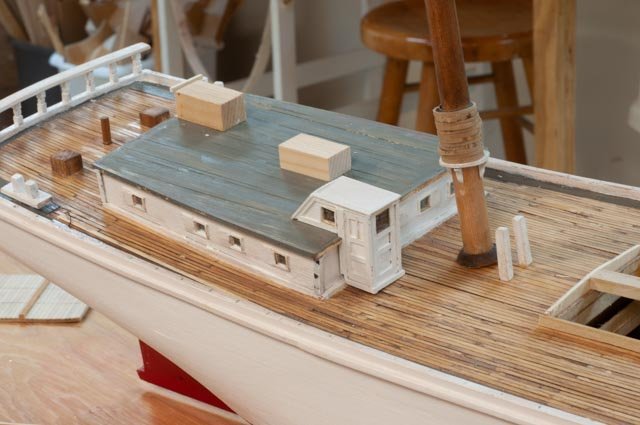
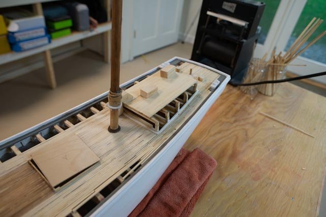
Post 26 Stain the deck and begin deck furnishing Staining and finishing one’s deck is both a personal and historical effort. I rationalize that with some exceptions we only have black and white images, so when a nice warm cherry blend is added, it is OK. Another issue is making the rear admiral happy if the finished model is to stay home. In the first shot, I was experimenting a month ago with the dull brown of walnut stain on the Alaskan cedar. It was not approved for the home showing and warmth was required. 213. here we see remnant of the first trial using only “special” walnut stain [ vs dark] which is clearly a dull color. Around it is a light coat of cherry stain to start off with a warmer base. 214. here I have added the special walnut to the cherry base. For a finish I have chosen to use tung oil for my last several builds and I continue to like the affect. We all have seen many blogs discussing these choices, and they were helpful to me go get comfortable with this choice. If it were to be an RC model I would have used hand rub poly. 215. here is the foredeck with its first coat of oil. 216. here we are amidship. I am also experimenting with hatch construction. 217 here is the aft deck. In these photos I believe the warm color is nice against the blue green cold-water coloring. So, the conclusion is my selection is openly personal more than historical. Starting the deck furnishing: There will be many different topics here as we all know. I tend to work on a little of each as I go. That means my updates will have a little of each and not be by subject. 218 here is the foredeck area, I am working on the fore cabin. Quite rough at this stage. Maybe on my next schooner I will have more things open to try to show what is going on inside. On the side of the hull I have cut out for the chain plates and added the waterway extension around them. There is also another piece added into the rail at the upturn for the raised bow. I needed this in fill as the fly rails go forward all the way to these shrouds. This added piece was an attempt to smooth out the line of the rail and the result is more like the photos. 219. here on the aft deck, I have installed the first section of fly rail and started clean up and detailing on the cabin. 229. here I had fun making the entrance to the main cabin. I need to now finish fitting it to the sloped deck. The two wood blocks on top of the cabin are only dummies for where the skylight and similar structure go for the aft companionway to the main cabin. They both need to be open frame. All for now
-
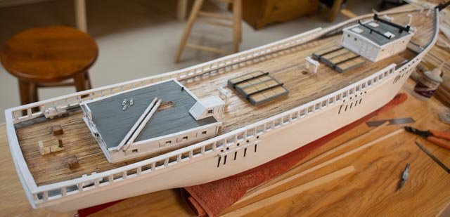
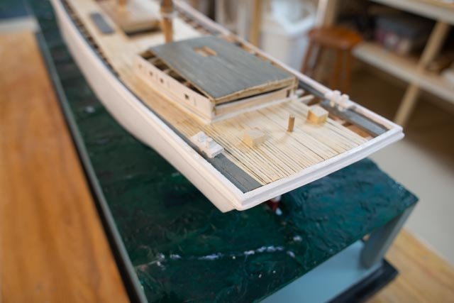
Post 25 Complete the decking A little celebration was held, as I finished the deck planking. I now need to start the sanding and rethinking about finish. We had our monthly guild session, and it was fun to get the input of diverse ideas of how to both finish the deck but then how to make sails. 206 here the planks for the raised foredeck have been sized and their outboard side darkened with magic marker. I must say I have enjoyed working with the Alaska yellow cedar. This has been my forst milling job and hopefully it will come out ok. 207 here in the mid deck area we see remnants of the experimental staining with “special walnut”. More on that next time, as I need to satisfy both historical reference, which is hard since images are black and white, and then the rear admiral, if I want the model to stay home. 208 here we are working on the main cabin as the decking gets finished. The roof will be painted but I believe the material was quite similar as I follow the anatomy of book. The planks were shown to be just a fraction smaller, but I believe that difference would not be seen. So, forgive me for keeping the 4-inch size. 209 here the fore deck is done but not yet sanded 210 likewise the after area is done but also unsanded 211 now for the overall look 212 and here is the bow shot Next up is sanding and clean up, some retouch up of waterways and staining the deck. I will then start the on-deck work, complete the cabins and hatches and the preliminary standing rigging. I think it’s fair to say we are sort of halfway home now. At some point I need a yawl boat too. All for now
-
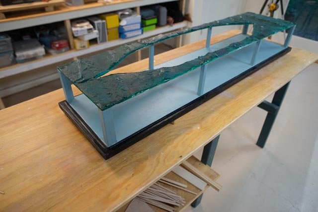
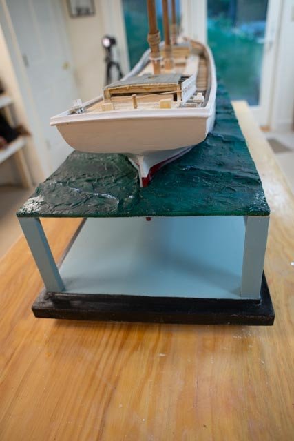
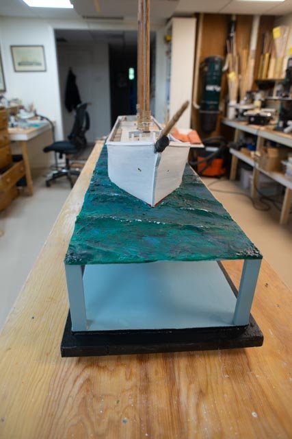
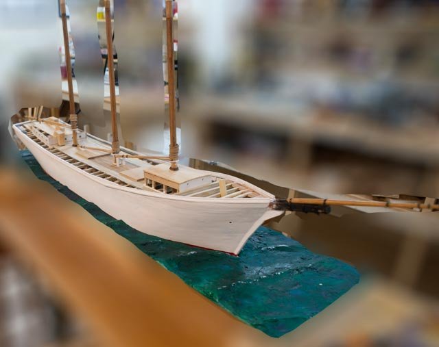
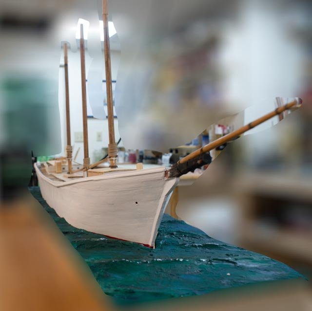
Post 24 Build the display I may be ahead of myself, but I wanted to get my display built and ready, so I can set the Schooner in its final place while she is resting. 200. here we are all with the at sea system assembled. 201 here we are in with Ada in place. 202. here looking below we see my attempt to paint out “water infinity”. The color, Jamestown Blue, is a bit of a guess. My thought is to use a little color but not have anything to take one’s eye off the hull. 203 looking from forward. Here I have a new issue. The hull is basically flat. I did not shape the seascape opening for a slight heel. I will think about that as to alter it will involve both cutting into the one side and adding on to the other side. Sounds like a wintertime study. 204 looking down from the stern we see some progress in the rough in decking and cabins. 205. and here we see the new raised foredeck coming together. Cheers
-
Keith Glad to hear from you. I followed your turnbuckle comment and did go back and catch up with your build. I am thrilled with your comment but admit clearly there is a very long gap between our turnbuckles. your machining, fine soldering and fit up of consistent components is just incredible to watch. the idea of jigs to make such components I will take on board. the example of placing the metal inside a piece of wood and then sliding on the table saw for controlled consistent cutting was inspirational. I am constantly struggling with that process. as an example I do all the filing and cutting of the turnbuckle barrels by hand. I have a milling lathe combo from Sherline that i inherited from my brother, but no real skills to use it. I saw you were doing very tight bends with tiny brass rod. I keep using copper and mixing it with the brass. there is just so much to learn. Thanks for your kind words and inspiration to go catch up on your work as it will surely help me. cheers
-
Allan thanks for the follow up I suggest through your work with Ernestina Morrissey. you have joined the ranks of Schooner lovers. I hope it keeps bringing you back the photos and books are fun to search for and through. I hope to get into that some more as Covid allows us to get back to the historical society this fall. cheers
-
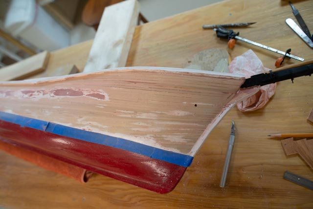
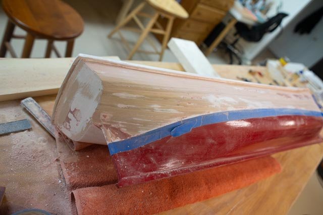
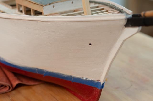
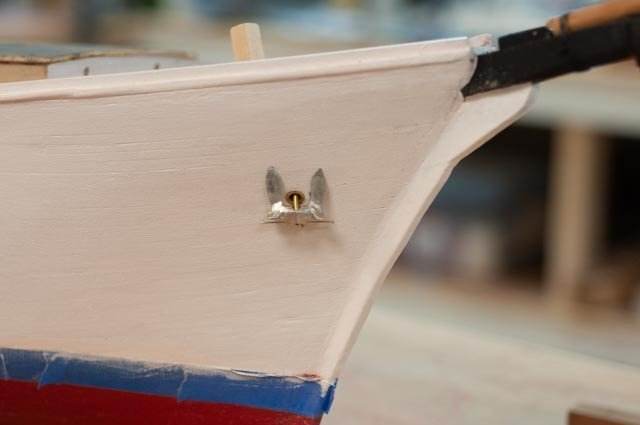
Post 23 Turnbuckles and bow finish I need to get going with the few production items. These are the things that I will either make or procure and adjust like blocks. Turnbuckles need to be made. Only radio sail ones seem to be available. I also want this build to develop my learning, so the previous version is improved upon. I shared those images before. 190 here we are putting together an assembly based on that previous build. 191 here we are looking at it. I tried to make a smaller ring by bending copper wire, but that won’t do. I want to see the threads that the little machine bolts have. Even though one of them will be backwards. 192 as shown in early posts, the top clevis is more like a shackle with the wire rope spliced around the pin. The thimble will be solid, but that detail is much later. 193 I have taken some 22-gauge wire and made rings on a few size drill bits. I like this size. 194 here is the saga. Moving up the photo we see that the lower ring fitting has a shackle for the chain plate. I made three sizes of shackles and chose the middle one. At the top the new parts come together. 195. here is my prototype for the chain plate and main shroud shackles. Now I need to make about 60 of these. Hopefully we’ll be OK. They need to be galvanized then dirty. More on that later Just to show I have decided to backup and redo the hull finish. A colleague at the Downeast Shipmodelers Guild in Bath had shared with us a few years ago, that a big mistake often made by us newbies was being too delicate with our sanding. He told us take it back down and do it again. That was specific to fiberglass over wood in RC models, but the theory needs considering. 196. I got a new utility tool last winter to work on a flooring project and used the sander attachment to take the hull back down to the wood and now can start over with painting. The long stretch with fill is unfortunate. It is there where the unsupported bulwarks were built independent of the main hull molds. If I had understood that the deck was raised, the molds would have been extended and that deformation would never had occurred. O well. 197. the transom also had added planks that protruded a bit and needed rough sanding to come flush with the remaining planks. 198. here we see the new bow. Back to an early post, I expressed my desire to see the planks through the paint. This is no museum piece, but I think I got the look I want. I put some exacto knife slices through the filled area, and that came through too. 199. I thought for fun to see what the anchor will look like. I happened to have this anchor from Bluejacket in my stash of extra stuff. All for now
-
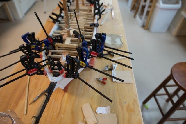
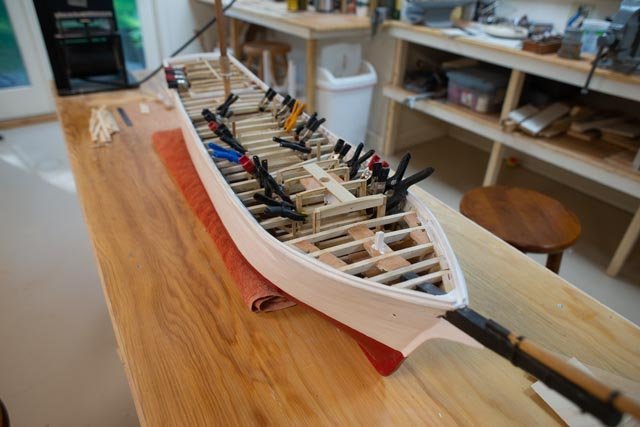
Post 22 Fixing the bow I left off having figured out a plan to fix the bow to follow the shape from the photos. It had to come up another 3 feet in scale , so here we go. I had already raised one foot form the bath schooner plans, so the total is a four foot raised deck over the windless. 181 I built up the planking on both sides. 182. it took quite a few planks to get there. 183 here we are gluing down the chock rail. 184 I continued pecking away at the decking in the aft area. Now a few fun photos to see where we are and where we are going. I painted up the sea, and added some blue tint and white highlights. I also painted the starboard side with a satin white to soften the hull a bit . 185 we see a normally preferred view . wow if the sea could be two feet wide wouldn’t that be fun. 186 this view is like the main historic photo of the launch. The high bow is now much more like the photo. I think though I need to consider a rough sanding and start over of the hull finish. This close up view leads me in that direction. 187. here the forward deck supports are mostly in and the new Sampson post is set. 188 here on the aft cabin we have some walls ready and the deck coming forward. The decking is now another area for sanding and clean-up work before staining. I also need to guess what color for the deck roof. I am thinking to use the same dark gray on the waterways . 189. this photo shows what will need to become a preferred view due to the narrow confines of the sea. I will need to take several shots and blend them for enough to be in focus too, as this wide angle lense does not get enough depth. All for now
-
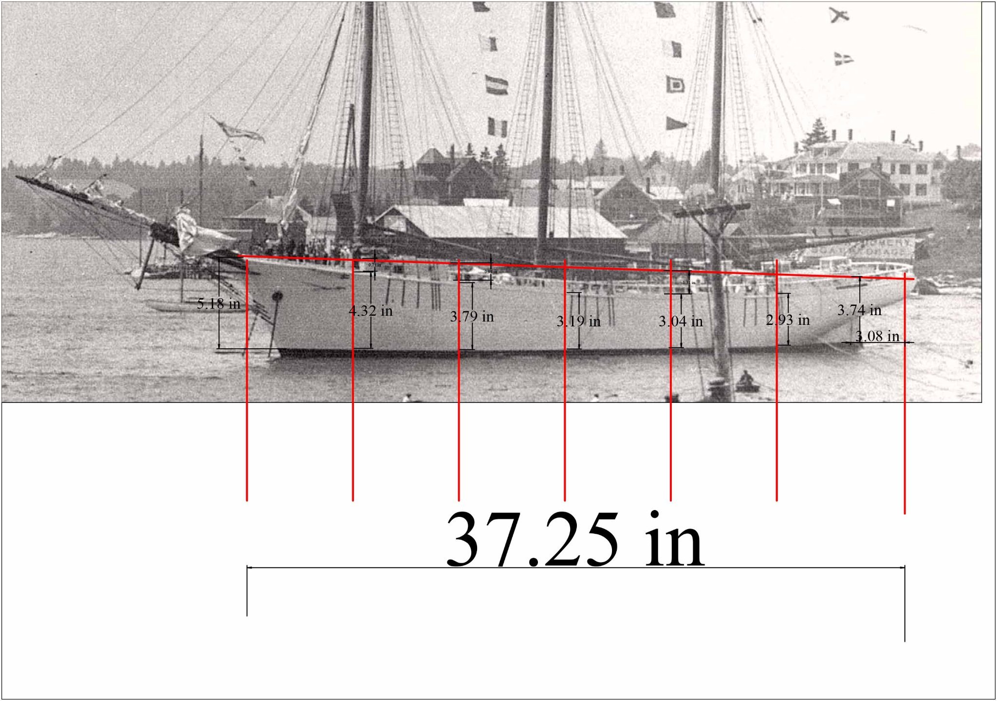
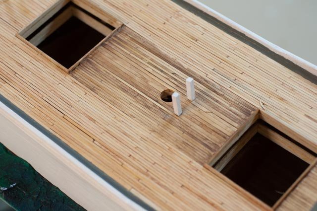
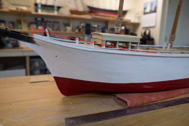
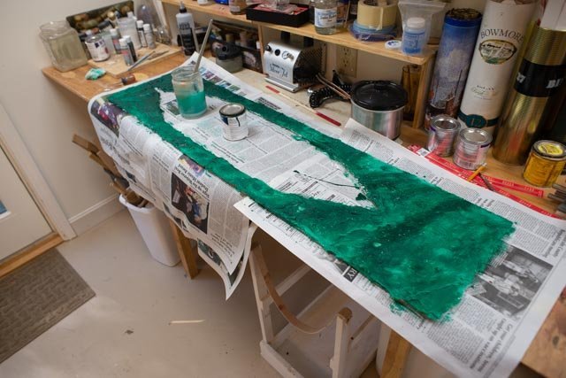
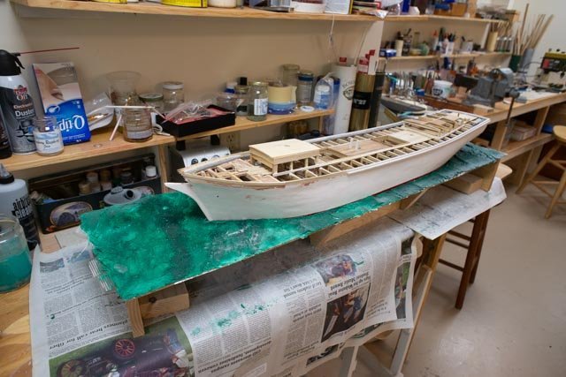
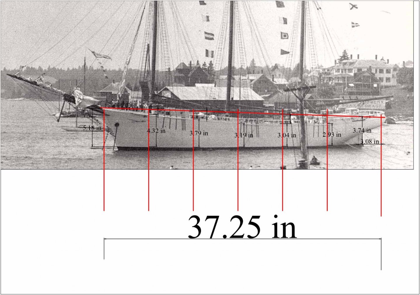
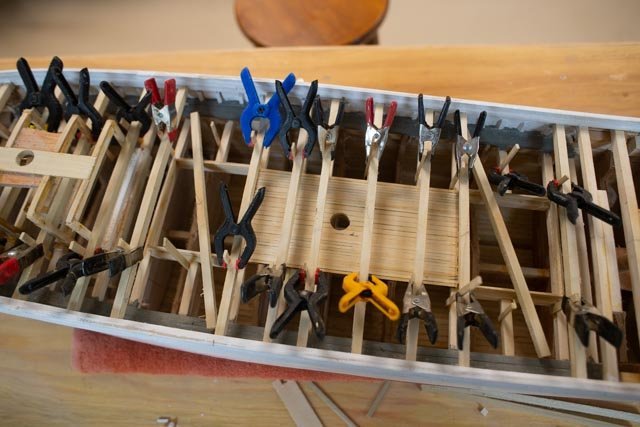
post 21 onward with the second part of the deck oops fix I had to chuckle again at myself as I got ahead of myself on the fore deck. As I progressed, I just knew something was wrong. The gas engine that is in the starboard side of the forward cabin needs to lead a chain forward to run the windlass. Men must get there and receive the anchor chain and drop it though a deck that is below the high foredeck. Thus, there must be a break in the deck and the foredeck must be higher. Further observations of the launching photos helped me come to what I finally hope is the right solution. Before we get there, I did some more deck work. 172 here we are replacing the center section of decking to get us back to where we thought we were a few weeks ago. 173. here based on that review I rebuilt the fore cabin to its corrected height assuming, as the Bertha details show, that the deck carries under the fore cabin. In this photo we see I got ahead of myself adding bitts and things. They have all since come out. 174 here is an extreme cropping of one of the launch shots. One sees clearly the people standing on the raised foredeck and the top of the forward cabin is waste high. 175. here is a good shot from the fly rails book showing the fore deck relationships that were so typical. The floor of the fore cabin is clearly 4 or so feet down. That allows the equipment to drive the windlass that is located below the raised deck. 176. here I am OK to continue work on the after-deck area Finally, the solution 177. I took this photo into Turbo cad and scaled it to the full model size. I set verticals at 6 inches spacing and measured from the water way to the water line. When I checked the same dimension with my current build…. 178 here we are looking at the current front shear line. We must remember we built this as a Bath built schooner and only have these photos to consider making it a Boothbay Schooner. The late Jim Hunt shared with me his findings that he Boothbay Schooners were known to have very high shear. Well, we just reproved it again. The dimensions that came out of the comparison suggest that I start tapering up the shearline to a point roughly ¾ inch at the line of the fore cabin to 5/8 inch at the bow. Oh well more demo…. I have already started Fun with the display planning I am trying a new process to make a painted sea to carry the schooner. I have never done this and am not yet committed, but it is fun to try this process out. 179. here we are painting out the shaped spackle sea with left over paint from the Bowdoin diorama. The can says forest green and being old is a bit thick. With my liberally adding water to the brush, inconsistently, I got a large enough variation to look something like salt water off a rocky coast. Next up it white highlights etc. I must remember less is more!!! 180 Here is the first attempt to sit in the water All for now
-
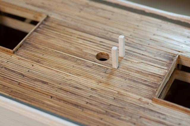
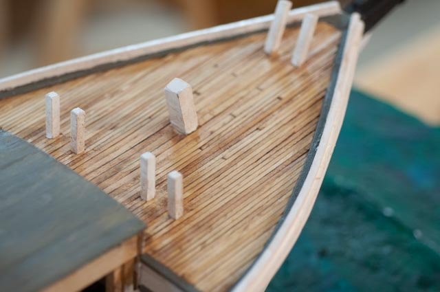
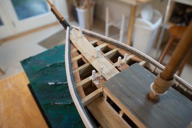
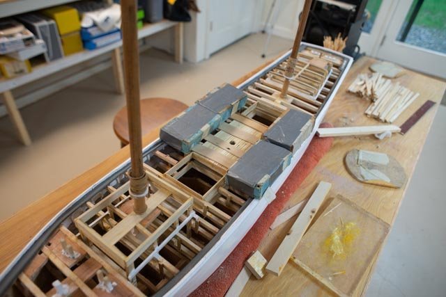
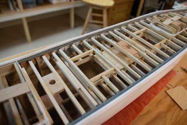
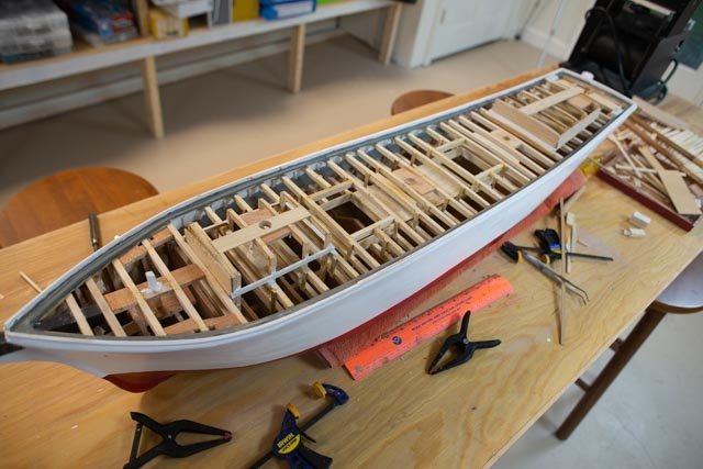
Post 20 First part of fixing the big deck oops and starting production items The first thing I needed to do after deciding to fix the big oops was to add the upper deck across the mid-section. I will worry about the bow later. 157. first up was to mill out, shape and set the new deck beams. The clamps are gluing vertical braces to hold them in place and add to future strength. 158 here we are gluing the new deck beams in place. 159. this is the first view of the new overall effect of one deck. 160 here we are fixing the waterway at the bow. 161 here all the beams are in, the waterway is set, and first coat of paint on. 162 this is a fun shot as it shows what should not be. Obviously, there is only one deck in this schooner. The lower main deck with its waterway and bulwarks is still there but not what I now believe is the right configuration for Ada Cliff Production. making those little parts During these projects that are several components to be prepared. Sometime we simple buy them like blocks and sometime we need to make them like turnbuckles and balustrades. Just to show that the work is now begun here are two views. 163 this view is from previous study and my build of the schooner Charles Notman. We see the balustrades come forward as far as the poop deck. On that schooner, it was very unusual as the poop deck came all the way forward past the main mast. Regardless, we see the difference of the main deck and raised deck. We also see the turnbuckles I made as part of that build. 164. here I am using a similar technique as before to start making the balustrades. I am using maple this time to turn and shape them using files. We need about 100. So, a few each day is the way I try to work. 165. here is the first pile of blanks. 166 here from my past build we see the main turnbuckles. I have found more photos and they all show about the same sizing. The main deck shrouds our held by roughly 5 maybe 6-foot turnbuckles. we need about 70. 167. here on the top mast, they were a bit smaller. I tried to make them 4 feet. [ Note Charlie was a sailing rc schooner thus the muslim sails] 168 looking at the launching photos of Ada Cliff, we see the turnbuckles and the chain plates are about the same size. I will go with 5.5 the compromise feet for both. Now I want to improve on the fabrication that I did before. 169 starting off I am where I was before. Here I am soldering the clevis. I am using a bent brass strip and a 0 hex head machine bolt. The steel shroud will be spliced to a pin in this clevis. 170 I am doing here again what I did last time. This process does not get the look I want this time. I solder a small ring into the end of a screw top machine bolt, that I file to the best shape I can. I have since rejected this method and will show results next time. 171 here is the assembly of the unit. The two ends are stuck inside a small brass tube that has been filled to open the sides. cheers

-
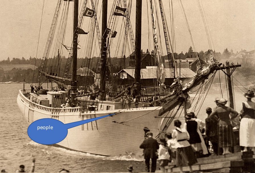
Post 19 Masts are stepped, waterway is done and first painting to get ready for deck is started and then another oops! Every once and a while a real brain cramp shows up… then again sometimes more research comes into play and we realize our earlier assumptions need to change. Let’s see what it was this time. The first issue is a minor brain cramp and it got fixed. The second one……… Following the plans I continued to make some progress…….. 144 here we see the foremast is set through the cabin. 145 here all three masts are set, and their tops have been adjusted to be the same height. 146. this shot is for the record. At least at this point the three masts lined up well. We’ll look again after all the rigging is done. 147. Here is an experiment. I have set the 8-inch seven king planks between the hatches. Next up I will need to sort out how to stain them. So far so good?.... Absolutely not!.............Two issues have cropped up. One is an error in building cabins. It’s no big deal, but the other is an overall concern for the basic design of the deck level. As to the cabins, I made up templates for the sides. I got them all on, but things looked odd. Back to the books and sketches and recheck the height of these cabins…….oops 148 remeasuring I found all the posts on the aft cabin are 3/16 "too high. That will not do 149. here they are cut 150 here they are reglued 151. here are the templates on the fore cabin. It was not so bad. It was level and not following the shear line, so the aft post was high and the next two a little less. They were cut progressively to regain the right slope, parallel to the shear. 152 here they are being reglued at the right height. Fortunately, all this cutting and gluing is under the cabins and out of sight. Now for what I consider the big oops is for the deck construction. There are two opposing concepts in these big schooners. • in one the main deck located at the shear line carries through the schooner. Then the poop deck and fore decks are raised above it. That is what the Priscilla Alden plans and the Bertha book show that I have been following • in the other concept, there is only one deck level. Now that I have all these photos to study of multiple schooners, it seems that where the balustrade fly rail goes all the way forward to the fore cabin. That seems to happen because the deck is high throughout. 153. this view is from the book Fly Rails and Flying Jibs . I have been going over more and more views. This view clearly shows the balustrade rail goes with the fully raised deck. There is no poop deck. 154 this view is what I was building based on the drawings I was following. There is no balustrade fly rail along the length of the main deck OOPS 155. here we are right after launch. The fly rails go all the way forward. One can see people leaning against the rail back at the main shrouds. Another detail that I understand now is that there is no indentation of thinner planks making up a bulwarks above the shear line of the main deck. I have been curious about that detail for some time, as the photos show continuous planks all the way up. Now it all makes sense. there must be only one deck level. 156. here is a broadside cropped picture taken after the launch. My conclusion is that I need to fix this oops before moving ahead. If I use the photos of the schooner I am building, I believe I need to stop and fill in beams all the way to make one deck level. It makes no sense to continue as I am, because I would not then include the fly rail that is clearly in the photos. Arge
-
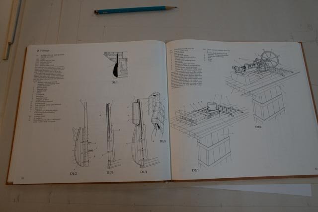
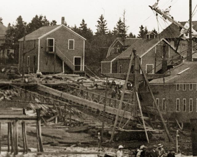
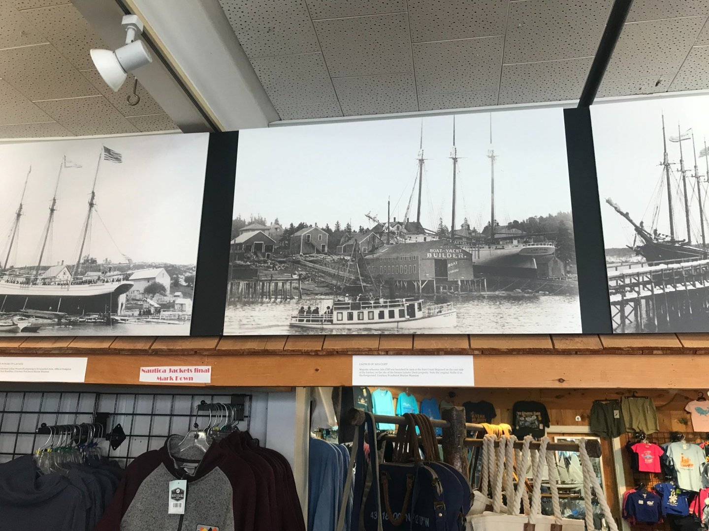
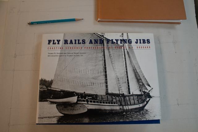
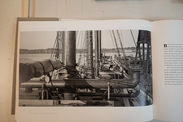
Post 18 Research update and progress with underdeck Now to share more of the research documents needed to avoid wild guessing. 134. from the Bertha Downs book I used these two pages for the rudder assembly. The left page shows the total ‘cut in’ aspect of the pintle and gudgeons as mentioned earlier. The Right page, left image, shows the parts that are visible on deck under the gear box house, that I hope to replicate. 135. This is a new book. It is called Fly Rails and Flying Jibs. It is based on an incredible collection of photographs taken of schooners. It is helped tremendously by the writing of Douglas and Linda Lee. Douglas I am told is a Naval Architect who through the main Maritime Museum recreated drawings and details for Schooners including a four masted[ Charles Notman}, five masted {Cora Cressy} and the six masted Wyoming. These comprehensive plans and details are critical for anyone looking into these schooners. As a couple they also owned and sailed the windjammer Schooner Heritage for many years. The book is an incredible photographic resource specifically for new England Schooners. There are also many pages of photos and text all about Boothbay Harbor, the center of significant schooner activity. The Boston firm Crowell and Thurlow used the marine railway in Boothbay Harbor and the adjacent acquired land on McFarland point as the center for building many four masted schooners and subsequently providing the maintenance until their failure in the late 1930’s 136 This view is typical of what can be seen for making decisions on what to show on the deck. This is especially true if one wants to model a schooner that was not just launched. The mast was clearly painted. I use this tone to compare with tones on the cap rail and pin rail below as I need to decide how to paint things. 137 this is a similar view from another schooner. The main deck bulwark is what I am building, the simple poop deck enclosure. I love the little porthole. 138. here we are looking forward. The deck planking that the Bertha book told us to make 4 inches and it looks right on in this shot. It is darkish and dull. I need to do that in stain if I want the jointing to show through. This cap rail in this photo is lighter in color than others. It is more like a gray popular on fishing schooners. Another important detail is the turnbuckles. I made them previously on Charles Notman. I will use a clevis on the top and a ring on the bottom. I find that orientation interesting as using the previous info building Charles Notman they were the other way around with the clevis at the chain plate and the ring on the splice…we all live and learn I share the next photo for fun. It is a mystery. 139. The original photo was included in Jim Hunt’s four serial articles in the Nautical Research Journal, on page 218 Vol 43 No. 4. Which was December 1998. It was credited with a file number from the Boothbay Region Historical Society (BRHS) but cannot be found at BRHS. I took this photo in the Windjammer Emporium Museum Store downtown where my 3 previous builds, all dioramas ,are displayed. It is a huge blow up that was done two years ago. There must be a digital file somewhere. It is important, because this is the photo that shows both Ada Cliff and the keel of the first four masted schooner, Marguerite M Wemyss. One week later…. Well, a little luck and thanks to the owner of the museum store we have recovered it, and I have a nice high-resolution version to use. The Original I learned belongs to the Penobscot Marine Museum if one wants to acquire a copy. 140. here is a cropped blow up showing the keel laid for the first four master based on the lines of Ada Cliff, the Marguerite M Wemyss. Ada’s Bow sprit is on the right side. progress update I continued to work on the fore ward cabin so I could step the mast 141 this view shows the dowel leading to the centering pin. 142 shows continued progress with the chock rail. 143 it is always fun to get that waterway on the transom. Now I have to think about all those turned balustrades. All for now.