
JerryTodd
-
Posts
879 -
Joined
-
Last visited
Content Type
Profiles
Forums
Gallery
Events
Everything posted by JerryTodd
-
 Got 2 yards of gray Supplex from a different supplier than usual. It was much cheaper than their normal price; a remnant maybe? It seemed a little dark, but not so bad in the photo, for the sails of a British frigate.
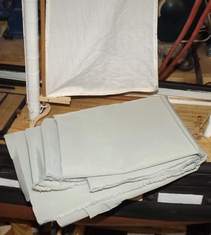
- 97 replies
-
- 3
-

-
- macedonian
- frigate
- (and 2 more)
-
I wager everyone that's built an extended frame model has had this little joke creep into their head.
-
Don't let these pudgy phalanges hear you, or I'll never get them to do what I want.
- 553 replies
-
- 2
-
-
- sloop of war
- constellation
- (and 3 more)
-
None of the boats I worked on glued the lines to the belaying pins
- 648 replies
-
- 2
-
-
- niagara
- model shipways
- (and 1 more)
-
Outboard
- 1 reply
-
- 1
-
-
And all the little support rods that held the bulwarks up... I think I'm going to look at pin rails next.


- 553 replies
-
- 5
-
-
- sloop of war
- constellation
- (and 3 more)
-
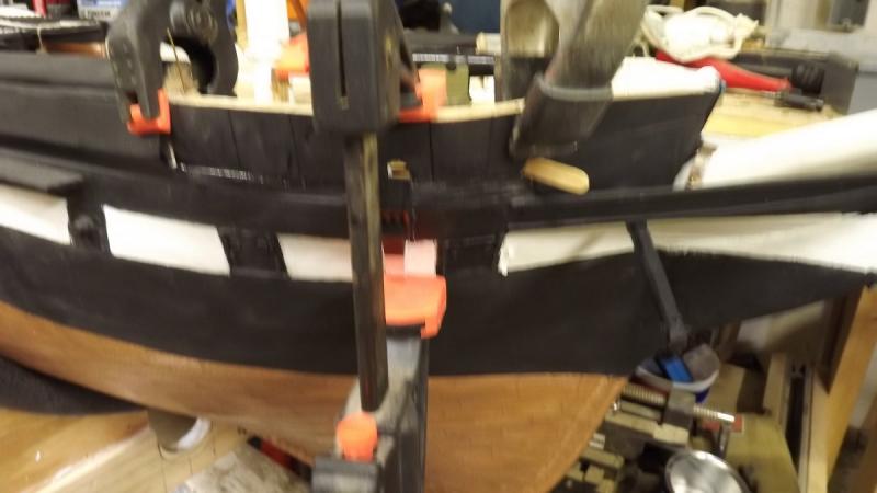
Epoxied the other bulwark on, which cracked and had to be glued and filled. Made the chain tyes for the tops'l yards with chain, shackles, and gin-blocks I've had since 2009. Corrected the front plates on the pivot gun slides. I saw a youtube video on photo-etching that looked pretty good. I'd like to make a lot of the hardware and details for these guns that way. Changed her rig to a barkentine and I'll be posting in the Gazela Primeiro log from now on. Just kidding. But still haven't come up with parrals and it's beginning to get cold in the shop

- 553 replies
-
- 8
-
-
- sloop of war
- constellation
- (and 3 more)
-
Stretch your lines before you put them on the model, it'll work out a lot of the tendency to twist, and don't glue lines to belaying pins - one of Murphy's laws of ship modeling is; you'll only ever need to adjust lines that are glued.
- 648 replies
-
- 2
-
-
- niagara
- model shipways
- (and 1 more)
-
Poor results with carpenters glue
JerryTodd replied to a topic in Modeling tools and Workshop Equipment
Typically when gluing wood with such glue, you spread glue evenly over the surface to be glued and clamp until it just comes out of the seam. To much and you "starve the joint" that is, you squeeze out all the glue. It's not odd at all that a couple of spots will easily break free considering there's very little relative bearing surface involved. -
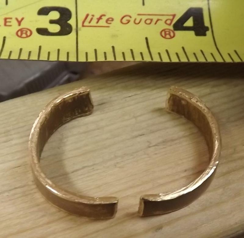
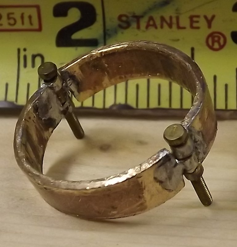
I tried plan C on a bit of scrap and it seems like it should work out. I hammered an end a little thinner, and worked it back on itself. I put a steel rod where the bolts pictured about will go and pinched it shut in the vise, then tapped it round. I can cut the notches that make it a hinge with a jeweler's saw
- 553 replies
-
- 1
-
-
- sloop of war
- constellation
- (and 3 more)
-
Maybe when America is "great again" they'll be giving those little beauties away, but I think it's more likely that getting one will be even less likely in the future. I'm pretty much stuck with stone tools and flints.
- 553 replies
-
- 1
-
-
- sloop of war
- constellation
- (and 3 more)
-
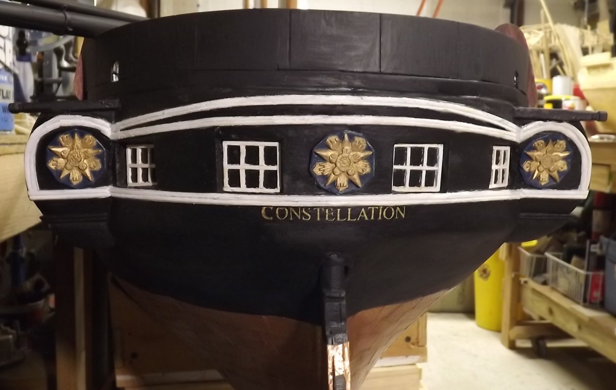
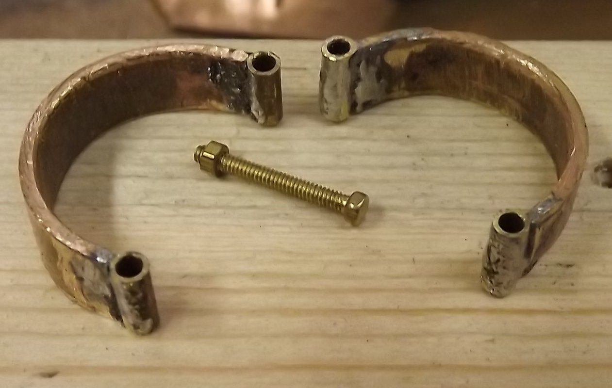
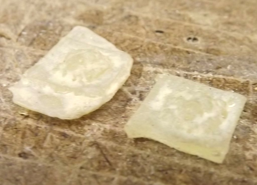
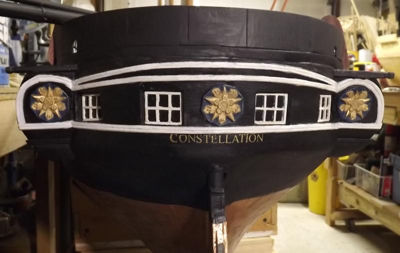
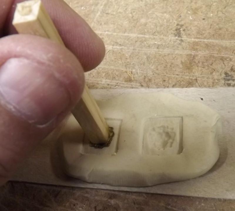
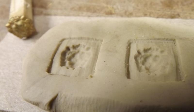
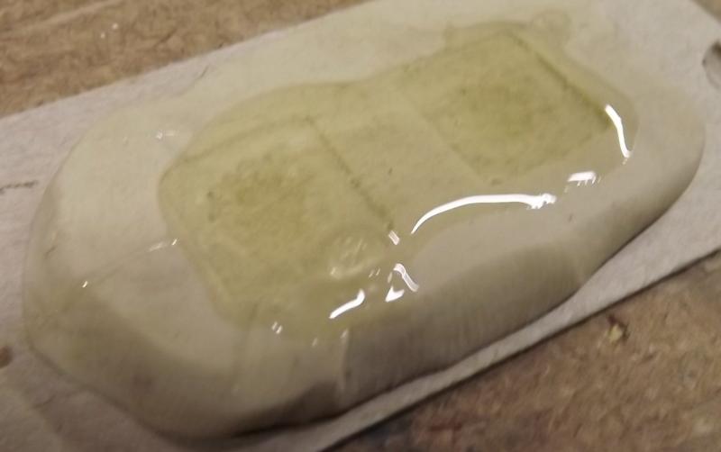
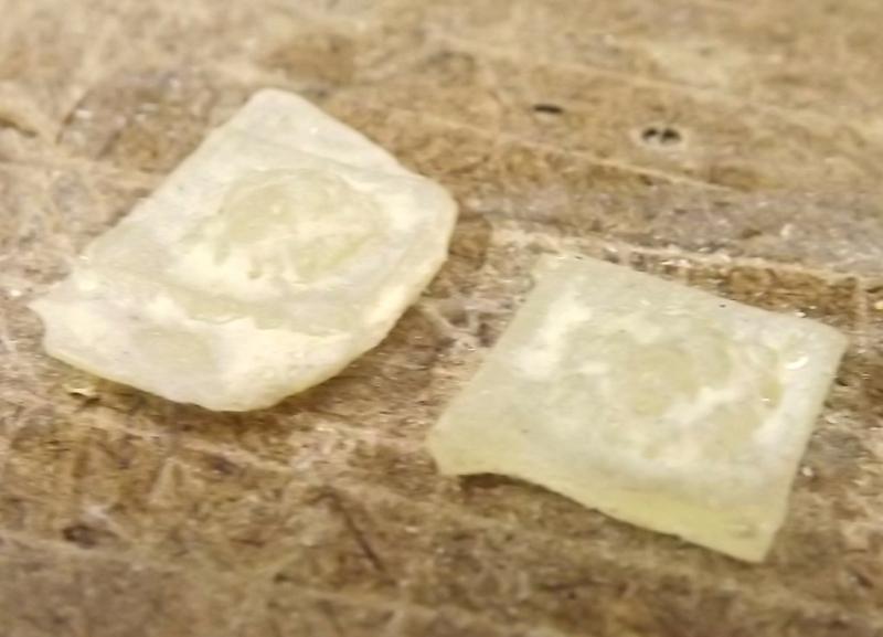
So, here it is with some filling, sanding, seams marked, and dry paint. I found a little stamped lion face, (I may have got this from you Vic), and wanted to make Constellation's cat heads by pressing it into some clay and casting them in resin, but I can't find my casting resin, so I tried 5-minute epoxy. That set up more like rubber than plastic, so we'll have to come back to that. The extra epoxy was used to glue in the starboard forward bulkheads. Today I made another attempt at making a parrel collar. I have some thick sheet copper chimney flashing left over from an old job that I use for lots of things, Constellation's and Pride's tillers for instance, are made from this stuff. At this scale it looks more like the actual parrels than the thin sheet-brass attempt before. So I cut off a strip slightly more than 3/16", formed it into the size circle I wanted, and cut it into two halves. Soldiered some brass tubing on the ends.... And cut the tubing to make the hinge portions. If it were only that easy. I had to re-solder the tubing on a couple of times, and finally when I thought it was done and was cleaning it up, another section of tubing came off. This would have been perfect, but obviously it wouldn't hold up to actual use, so it's on to plan C. Plan C: Hammer out the ends of the copper strip enough that I can roll them back to form the tubes like I did the sheet brass one before.


- 553 replies
-
- 5
-
-
- sloop of war
- constellation
- (and 3 more)
-
These are the same servos the fellas with the 1:24 scale SC&H Cruizer brigs and Surprise models are using, including the rudder servo. You should have no problems with the ability of the servos to handle your rig. The compression springs on the slides are something to think about. They are compressed most when the yards are square. If they are too strong they can bow, or even break the yard, not to mention putting a lot of load on the winch. Since braces tend to anchor on standing rigging, you'll see some pulling there as well. The springs only need to be strong enough to maintain tension - that tension keeps the brace on it's drum. I judged the length of travel for the winches by eye, and it's greater than it needs to be. Someone with a better mind for geometry and mathematics, or just a bit more trail-and-error than I invested, could probably determine a more precise length for the servo's travel and save some space in the set-up. I think I could lop off almost an inch in my case, and probably will on Macedonian's set-up. The extra length doesn't harm anything, but where space is an issue, it can matter. The "Mega-Sail-Arm" is a tall servo, and that may be an issue for you. I scaled a drawing of Epervier's lines to 1:36 and laid them over my Pride of Baltimore's 1:20 lines and with much less drag to your keel, you should have more head-room over more of the interior than Pride does. ie: You should have no problem with that sail-arm servo's height, as I have two of them in Pride. If you do go that route to control your fore-n-afts, get a "servo-stretcher" from Servo City or get a sail-arm set up for full 180° travel. You'll want it to be able to sheet properly out off-the-wind. Some transmitters, BTW, can program a channel in the same way. The Stretcher is great, it lets you set the center position and the amount of travel to either side all separately.
- 97 replies
-
- 4
-
-
- macedonian
- frigate
- (and 2 more)
-
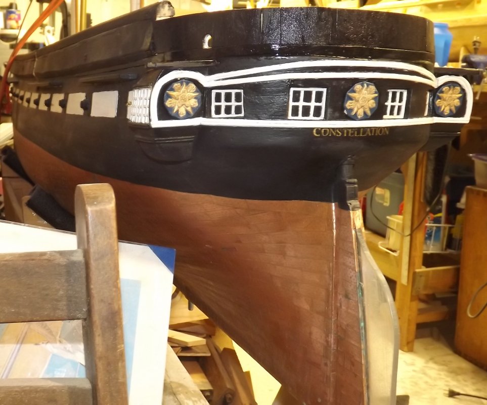
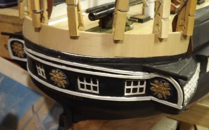
Card "hinges" applied Eye-bolts added Some white paint And some black paint too (still wet)


- 553 replies
-
- 7
-
-
- sloop of war
- constellation
- (and 3 more)
-
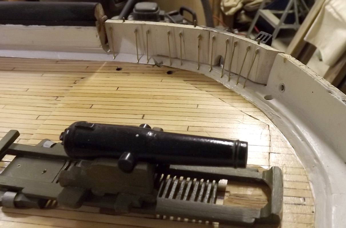
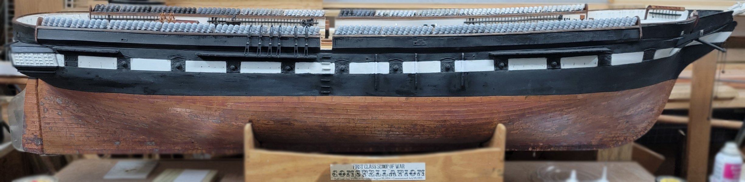
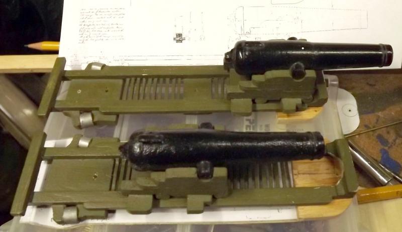
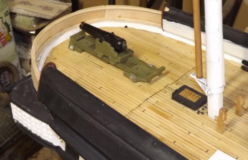
They're claiming now her pivots had iron carriages. I don't know their source for that - I think they've confusing them with the big guns installed on the gun deck for a short time. Those did have iron carriages, but that was 1871, not during the Civil War. I blocked out the brace holes in the bulwarks... and sheathed the inside.


- 553 replies
-
- 3
-
-
- sloop of war
- constellation
- (and 3 more)
-
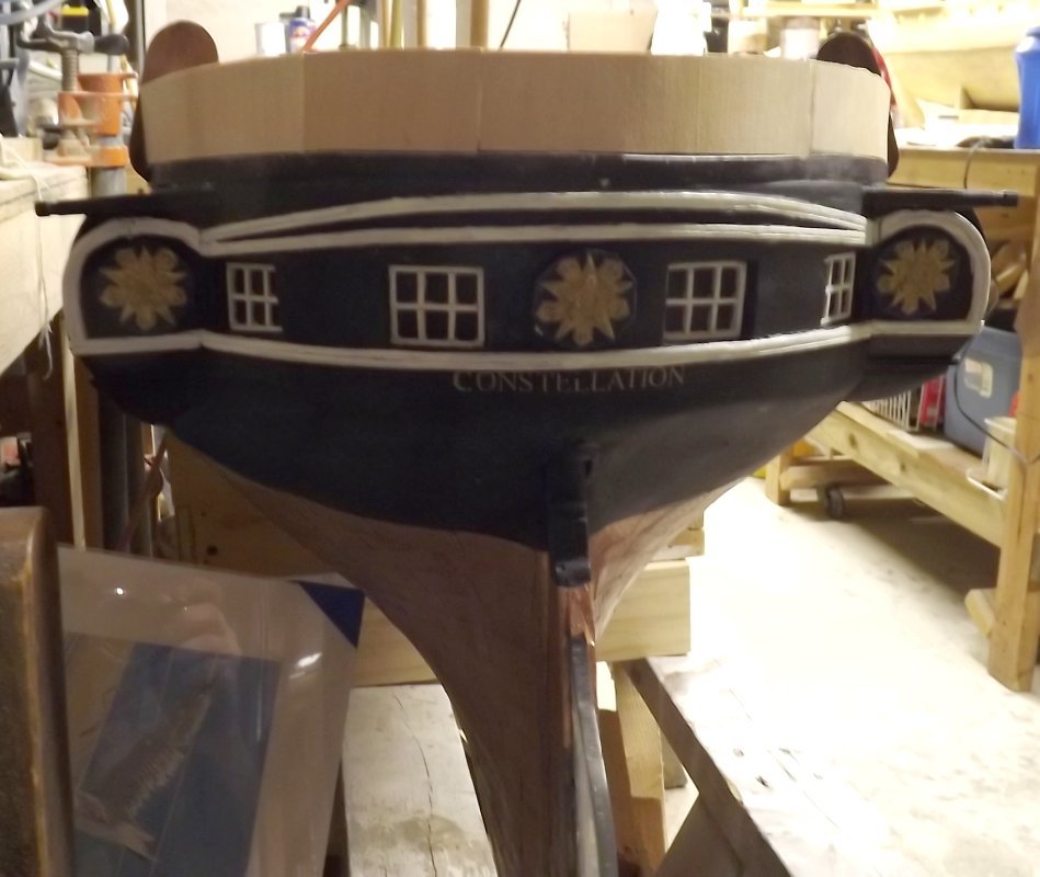
I took the pictures when I when to see Paul (director of the ship) years ago. The ship still had the forward bulwarks when she came to Baltimore in 1955. When they removed them during the conversion into a frigate, they just threw them, and the hammock irons, in the bilge. They reused all the hammock irons, but I suppose replacing the folding bulwarks hasn't been a cost priority.
- 553 replies
-
- 1
-
-
- sloop of war
- constellation
- (and 3 more)
-
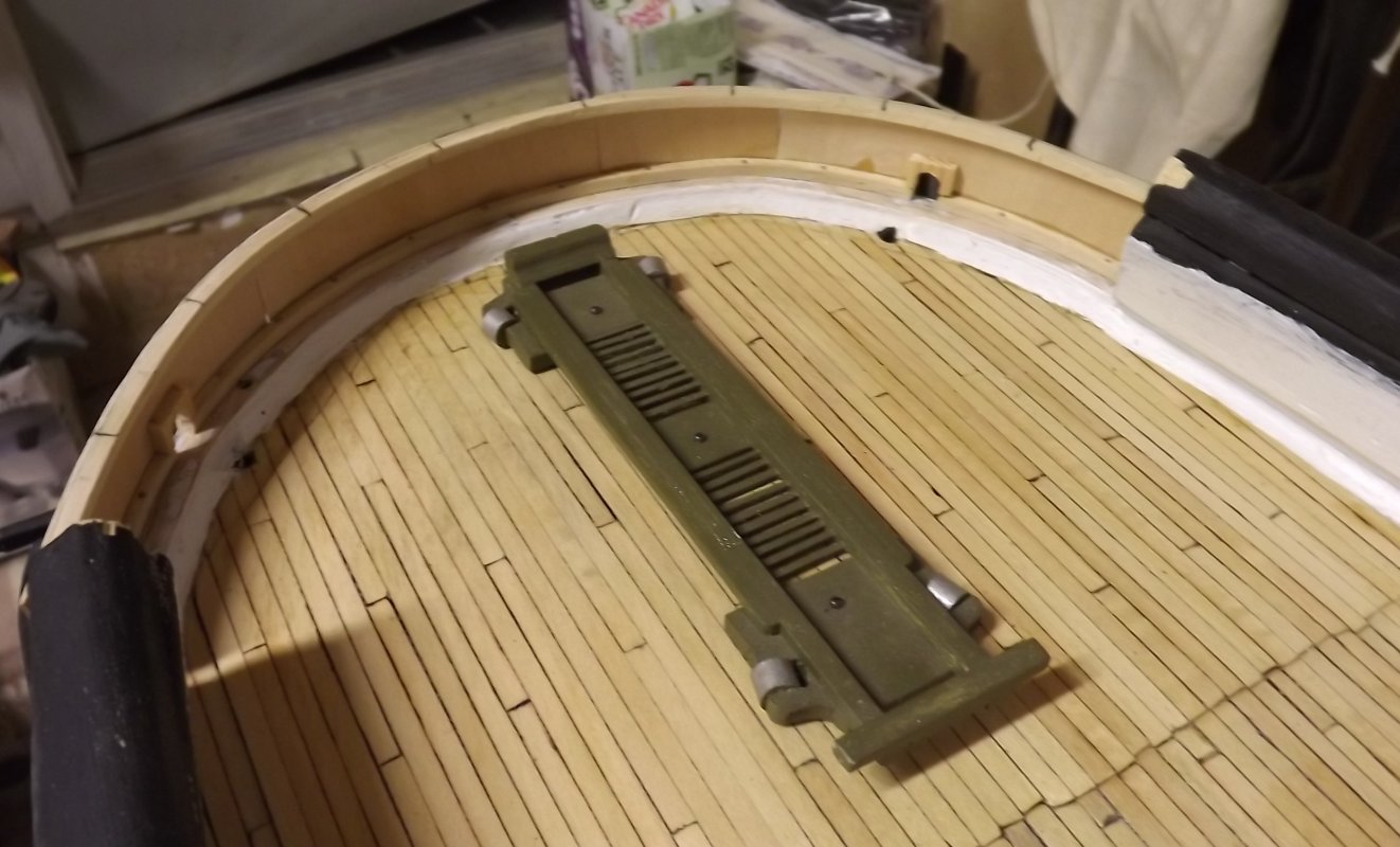
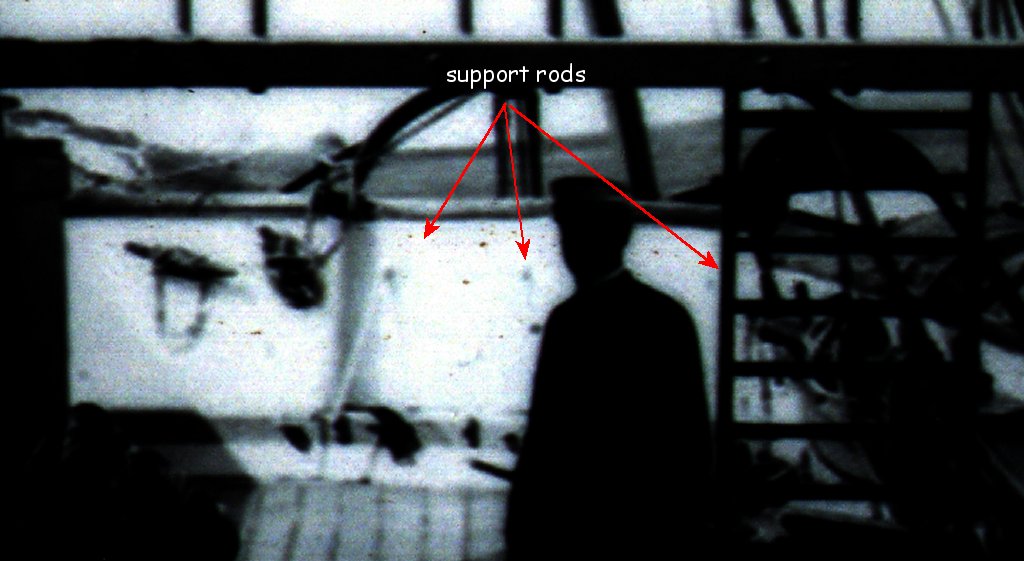
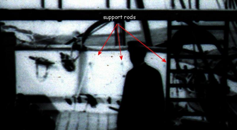
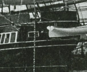
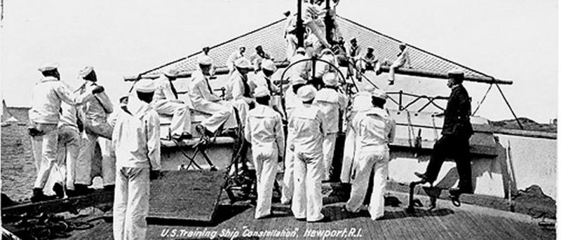
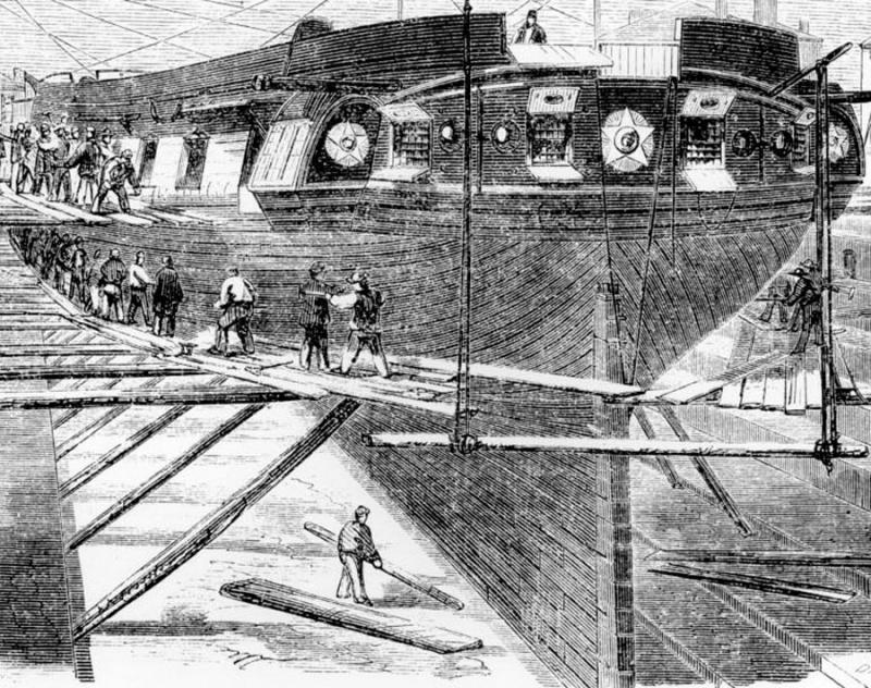
They really won't make much difference in keeping water off the deck, but if they were functional there would be a chance of one or more panels being knocked off or damaged in such an occurrence. The bigger problem is snagging rigging, though probably less of an issue than the ones up forward would be with the heads'l sheets hanging over them. The biggest problem is making the hardware to make them functional. This is one of the ship's original hinges from the forward bulwarks. It's bronze and the were 12 port/starboard pairs, each pair different. Back aft they are probably all alike, or more-so than the bow. I don't know how many panels there were back aft. The drawing in the last post shows one in the center, and another beside it about the same size. The drawing makes no implication at all of any other panels. If they were all about the same size, as would seem logical at the more symmetrical stern, there should be 9 panels based on the drawing, but... I've only ever found one photo that shows a stern panel open or removed. They were removable as this 1907 image shows... This 1884 image implies there were more narrower panels than the 1959 drawing implies; or something's changed since 1859. In this image from the same time frame, it's impossible to see there are any panels at all. There's at least one where the crane is, right of the sailors, and it has the opening for the main brace to come inboard. BTW; that horizontal timber below the hole isn't the bumpkin, it's a knee that braces it, where the bumpkin meets the hull is obscured by the crane. This 1890's image shows at least two panels aft, by the tell-tale support rods, but notice the center portion is now a fixed, solid bulwark. I'm guessing after the pivot guns were removed, the stern bulwarks were changed, but a few retained to facilitate handling the boats (note the jacobs ladders hanging aft in the 1880's images.) By 1914 there were no folding bulwarks on the ship's stern at all, just a wainscoted taffrail. I'm modeling the ship circa 1856, three years before the dry-dock drawing. I've never been able to find any information on the appearance of the stern, the pivot guns, and the folding bulwarks, fore or aft, from her early years - the dry-dock drawing is all I have ever seen. So, based on that, and that they were there to facilitate the function of the aft pivot gun, I'm assuming, they were all generally the same size with a center panel right aft, and four panels around either side, nine panels in all.


- 553 replies
-
- 3
-
-
- sloop of war
- constellation
- (and 3 more)
-
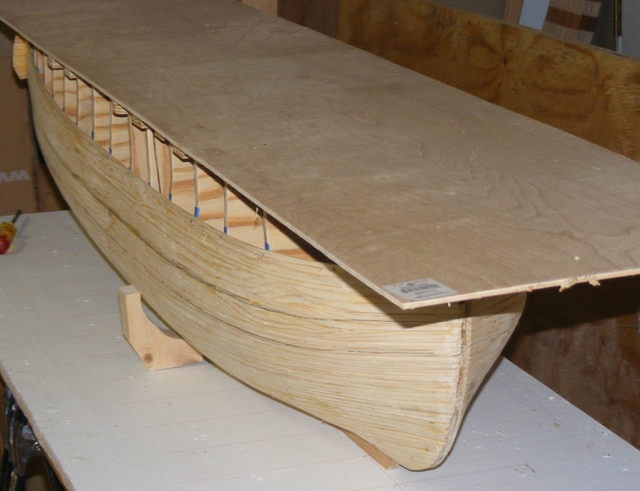
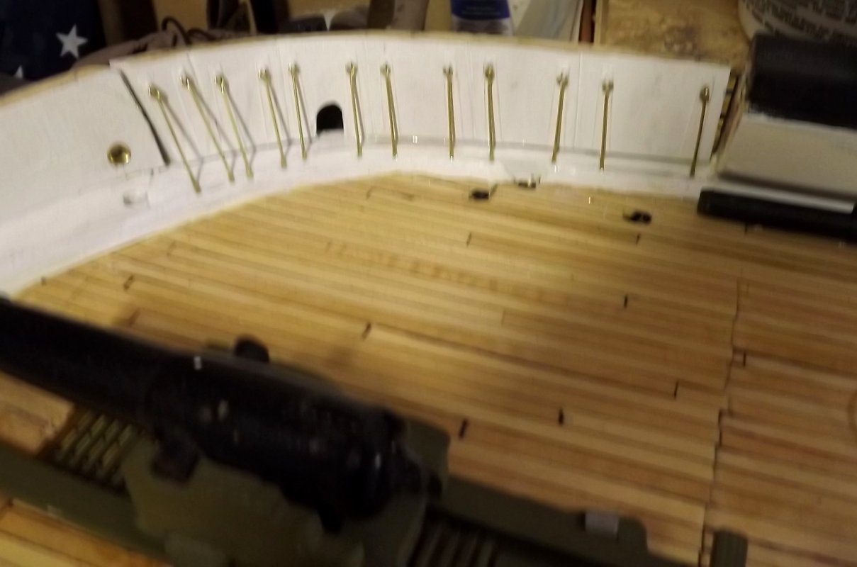
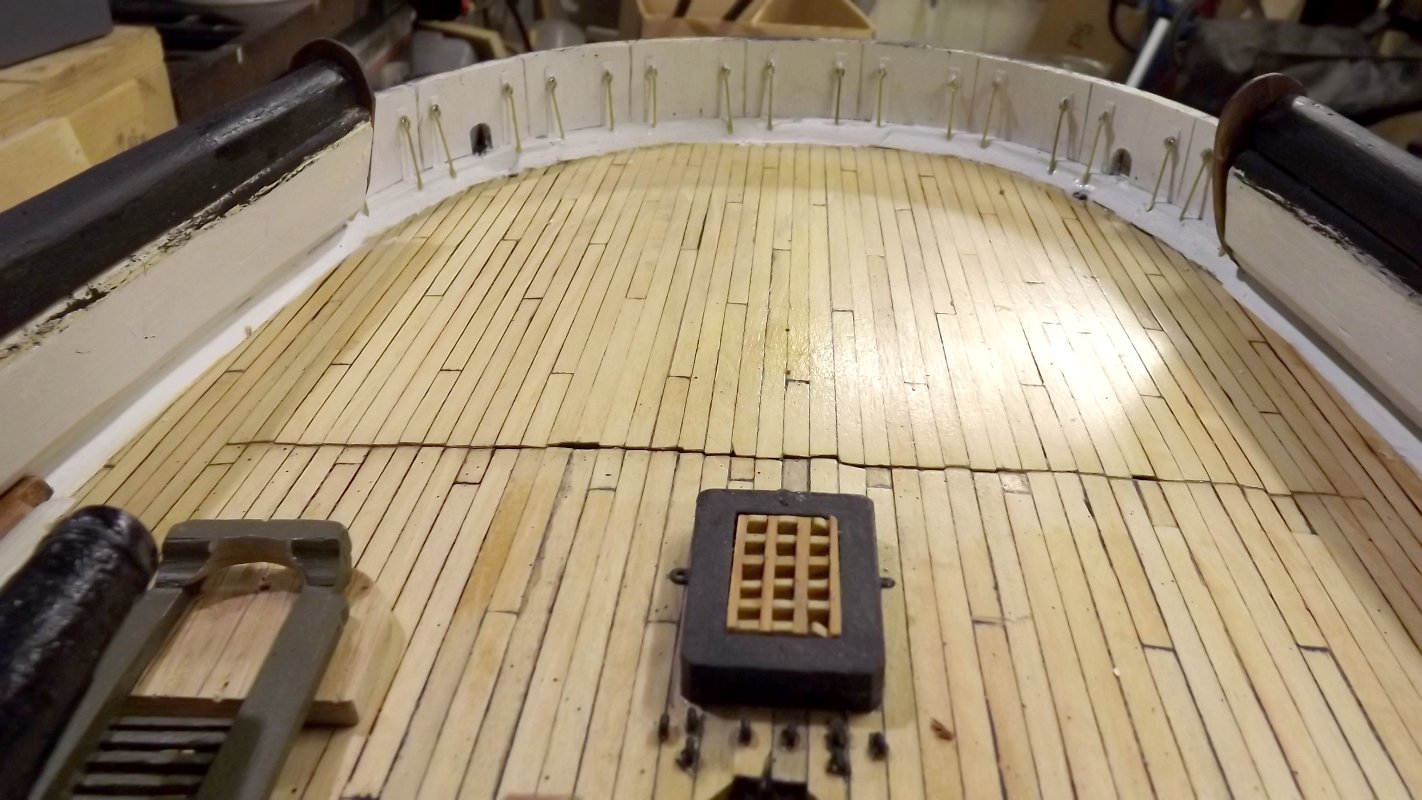
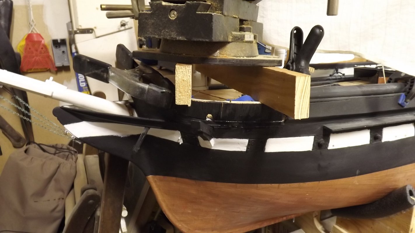
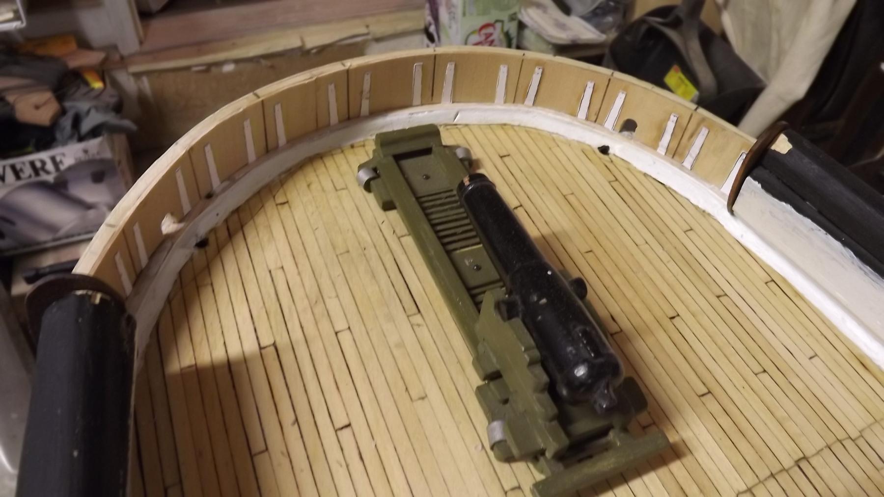
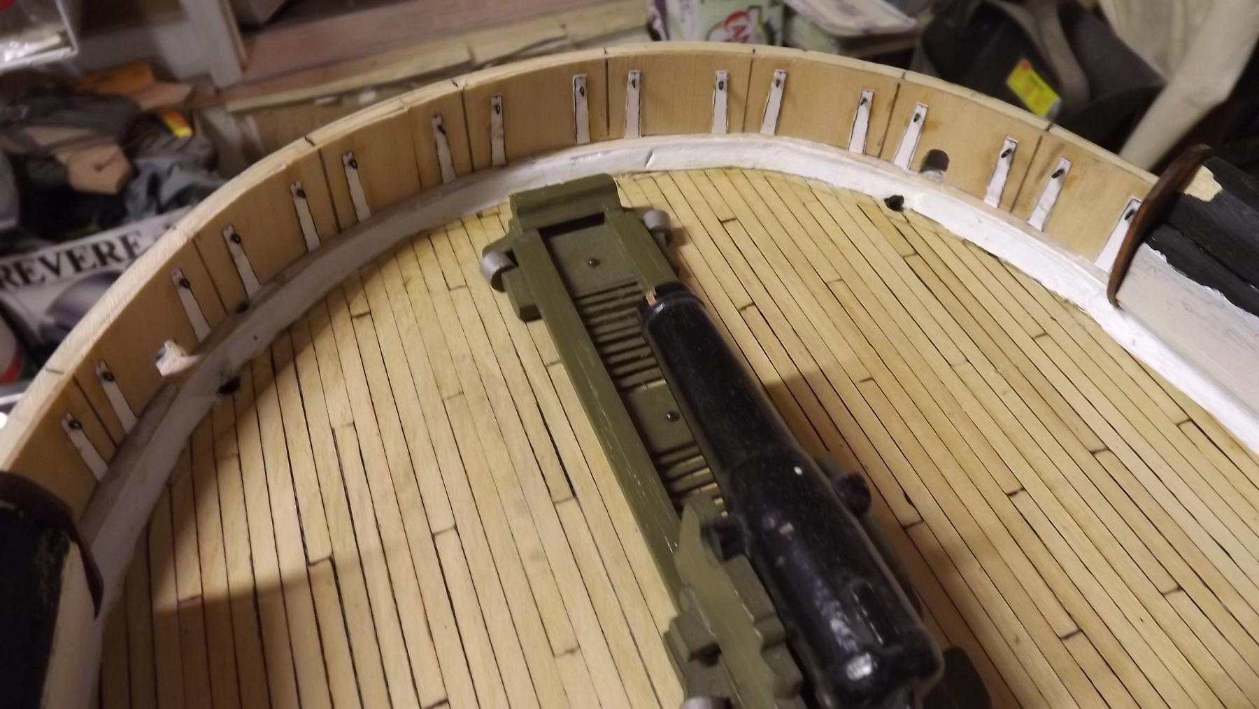
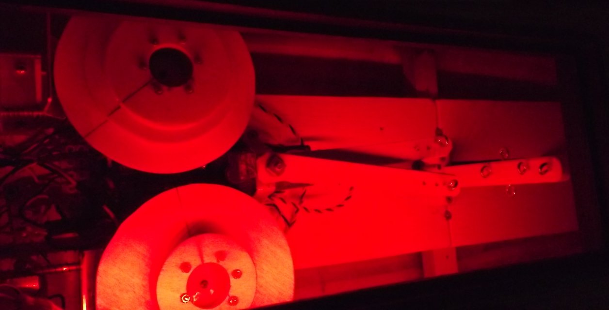
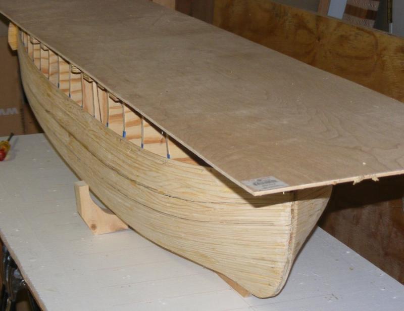
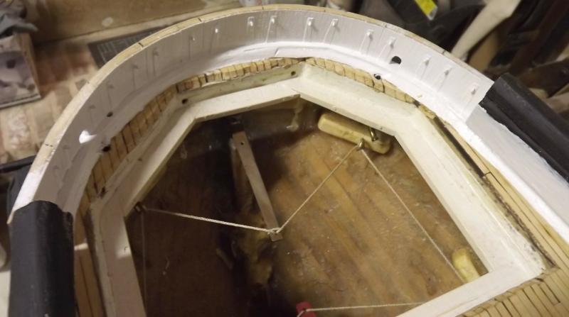
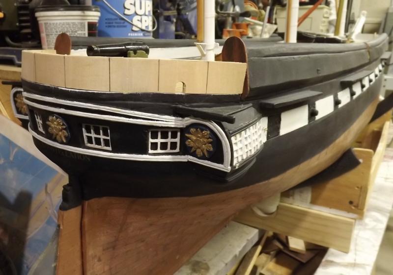
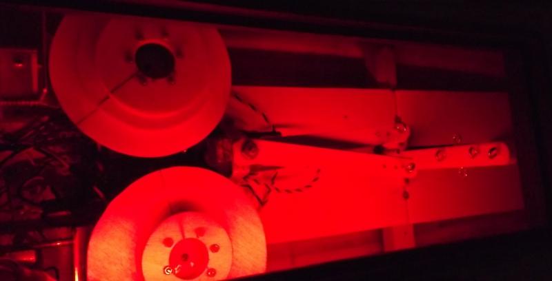
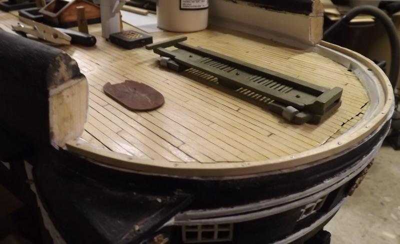
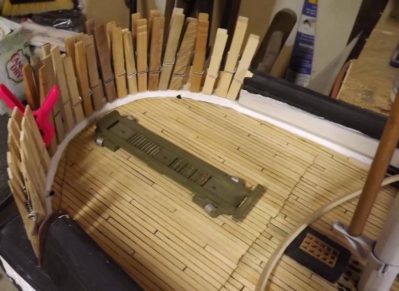
My friend Mark gave me a bit of LED strip left over from something he did to his old truck's dashboard. I hooked them up to ta 12volt battery and stuck them in the model. I've been thinking about some sort of lighting inside the model, I'm finding I need more light to see anything, as well as reading glasses for things close up. The LEDS are red which lit up the inside alright, but everything is red. I'm not trying to preserve night vision, but I may need to see colors when digging around in the model's guts. So, while I like this LED light strip, I don't think red LEDs are gonna do it for me. Mr Taylor will appreciate this bit... I began building the aft drop-bulwarks. Like the forward bulwarks, I'm not modeling the nine or so separate panels that make it up, rather I'm building it as a single unit and engraving the seams to imply the separate panels. Unlike the forward bulwarks, I'm building this one in place. I dipped a cut-off strip of poplar from another project in some ammonia and bent it around the stern cap-rail. Then I glued and nailed it down. Then I cut off sections of 1/32 bass sheet, with the grain vertical, and glued it on the outside edge of the strip I just nailed down. This is the outer sheathing of the bulwark. Another strip was dipped in ammonia and clamped on top of the lower strip to take the shape. Then it was glued at the top of the sheathing. Next the openings for the main braces to come inboard from the boomkins will be made, then the inside will be sheathed in the same manner.

- 553 replies
-
- 5
-
-
- sloop of war
- constellation
- (and 3 more)
-
Someone was paying attention The holes in the fair-lead bitt on Constellation are as polished as I can get them, but you're right, it's still not ideal. I recently cut an oversized cutting board made of that white Teflon like plastic, in two, and wound up with a 1/2" square strip from the center; wonder how that happened? I'm going to replace the bar with a portion of that strip. All my rigging will be walked from Dacron sail thread (polyester). Stranded synthetic line actually moves better through fair-leads than natural fiber line, non-stranded, or braided line. I think the strands make for less surface contact. Additionally, anywhere the line has to turn a corner tighter than 90°, there will be a functional block. In setting up Constellation's braces for that last sail I was using some cotton stuff I happened to have on hand, and there was too much friction for it to function, it was scraping lint off at every fair-lead, and you could hear the winch straining. I walked up the line in the picture and it was like butter. The videos were done with the Dacron line. Originally I was going to control the fore and main course yard braces, AND the three tops'l yard braces. Chafing and friction was why I reduced that to just the three tops'l yards.

- 97 replies
-
- 4
-
-
- macedonian
- frigate
- (and 2 more)
-
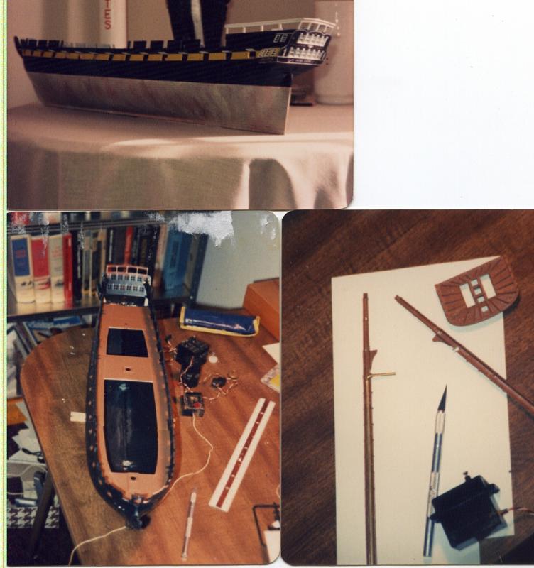
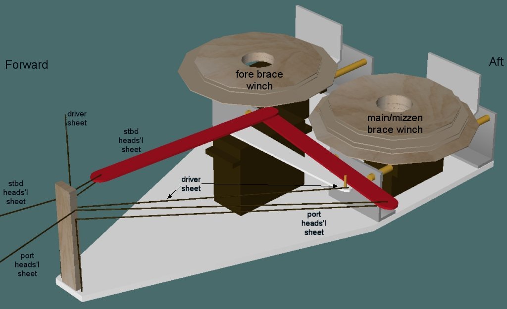
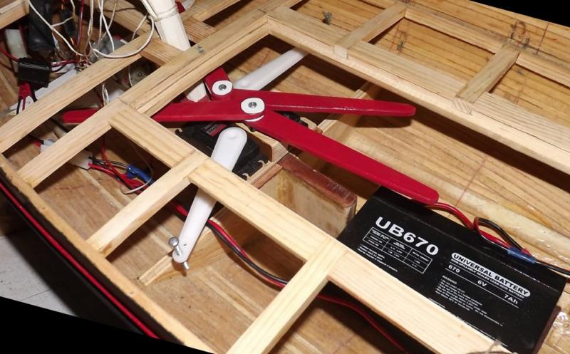
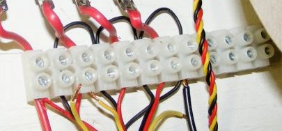
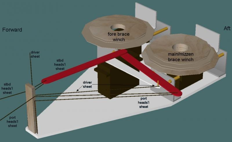
A 3D model of the servo tray used in Macedonian, Constellation, and any other square-rigger I build, and a bit of how it works and the reasoning behind it. Reasoning #1; to control the sails of the model as realistically, but as mechanically simply as possible. This system, I think, is as reliable and maintainable as I can manage, and can be adapted to almost any 1:48 scale or larger square-rigger without need of machining tools; 3D printers; laser cutters, special skills, talent, looks, etc. (It would fit in smaller scale models, but may require smaller servos which may require hacking regular servos into winches and so forth, thus increasing the complexity for some folks.) The wooden disks are the winch drums for the braces each on it's own HiTec HS785HB winch servo. The right one (your right) is the main/mizzen drum, the left one is the fore. These control the tops'l yards on their respective masts. Two drums for each yard, one takes up as the other pays out. The servo and drum slide fore-n-aft on rods with compression springs to maintain tension on the braces so they don't fall off their drums and tangle. Adjustment of the braces is done at the other end where they anchor in the rig. It's not practical to try to adjust them at the winches. The large servo is a HiTec HS815BB "Mega sail-arm" servo with a "servo-stretcher" installed to give it a full 180° swing. This servo controls the driver sheet directly on it's own (white) arm, and the heads'l sheets on a pair of (red) arms mounted port and starboard. The red arms are not connected to the servo and may move freely. One or the other is pushed by the servo's arm to sheet the heads'ls. As shown, the heads'ls are sheeted all the way in on the port side AND the driver is sheeted all the way in as well. The starboard heads'l sheets are loose. Only a single heads'l sheet per side is shown, but typically there are three p/s pairs. The sheets come from the heads'ls forward (left), pass through a fair-lead on the post shown at the far left of the tray, run to a sheave in the end of the the arm on that side and back to the post. It then leads down to an anchor on the tray where it can be adjusted as needed. I'm thinking of using a portion of one of these to anchor the sheets on the tray: The whole tray is held on the "mechanical deck" inside the model by three screws, and can be removed through the main hatch as a unit if need be. No modifications have to be made to any servo, there-by not voiding any warranties, etc. Sailing Constellation has shown that control of only the tops'l yards is sufficient so long as all the squares are sheeted snug; and works better than controlling the course yards as control is imparted to the center of the stack of sails, rather than near the bottom. and click the pic for another video...
- 97 replies
-
- 4
-
-
- macedonian
- frigate
- (and 2 more)
-
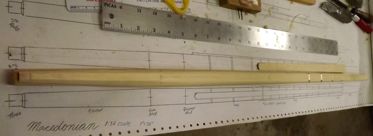
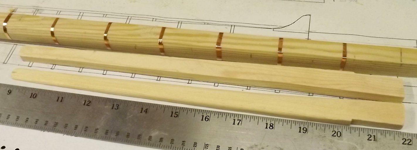
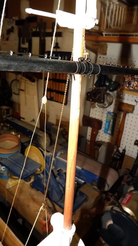
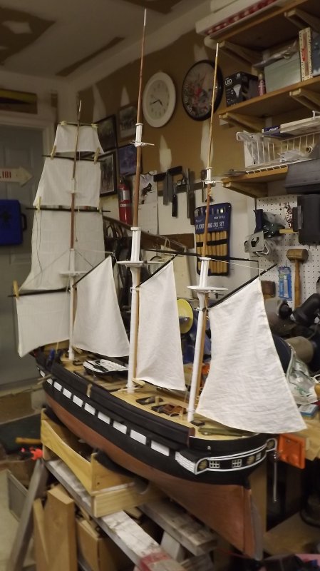
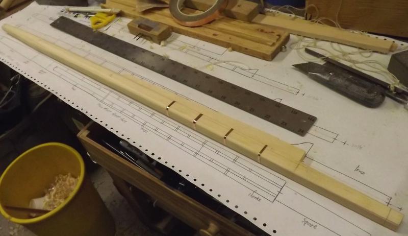
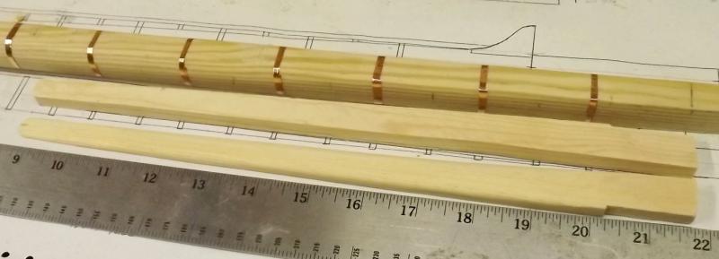
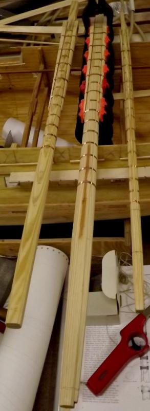
Ok, back in the shop and got the main mast 8 sided; round; where it needs to be roud; banded under the cheeks; cheeks made, shaped, and affixed; banding over the cheeks applied, all clamped up; and what looks more like a Polynesian war club than a mast is waiting for the glue to fully set. The main and fore need rubbing paunches, and all three need their tenons cut top and bottom.

- 97 replies
-
- 3
-
-
- macedonian
- frigate
- (and 2 more)
-
Wood masts for a plastic model... Tips?
JerryTodd replied to SomethingIsFishy's topic in Plastic model kits
In the several Revel Constitution/United States models I've built, besides replacing the smallest spars with wood, the topmasts and lowers as well as the lower yards are hollow. These I filled with epoxy (JB Weld) and a metal rod, usually a length of metal coat-hanger. A couple of these kits were made to sail by radio-control, and the course yards were controlled by a rod inside the lower mast to a bell-crank below deck, in effect, achieving the same result as above. BTW: I've found bamboo skewers and chopsticks to be nice material for very light spars. Up in the storage areas of the Naval Academy Museum in Preble Hall there were at least two dozen Revel Constitution models given by alumnists to the museum. Every one built out of the box, and every one with bent and deformed plastic spars.