HOLIDAY DONATION DRIVE - SUPPORT MSW - DO YOUR PART TO KEEP THIS GREAT FORUM GOING!
×

JerryTodd
-
Posts
874 -
Joined
-
Last visited
Content Type
Profiles
Forums
Gallery
Events
Everything posted by JerryTodd
-
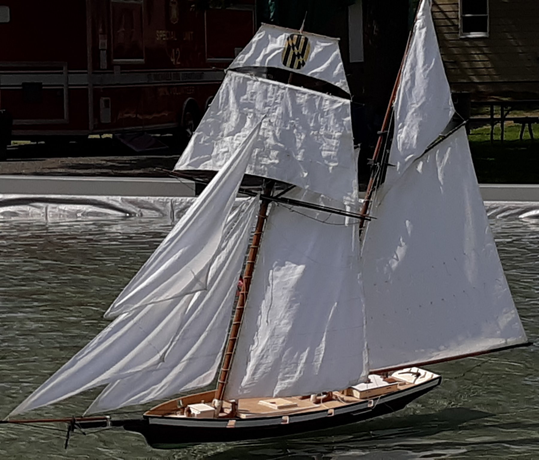
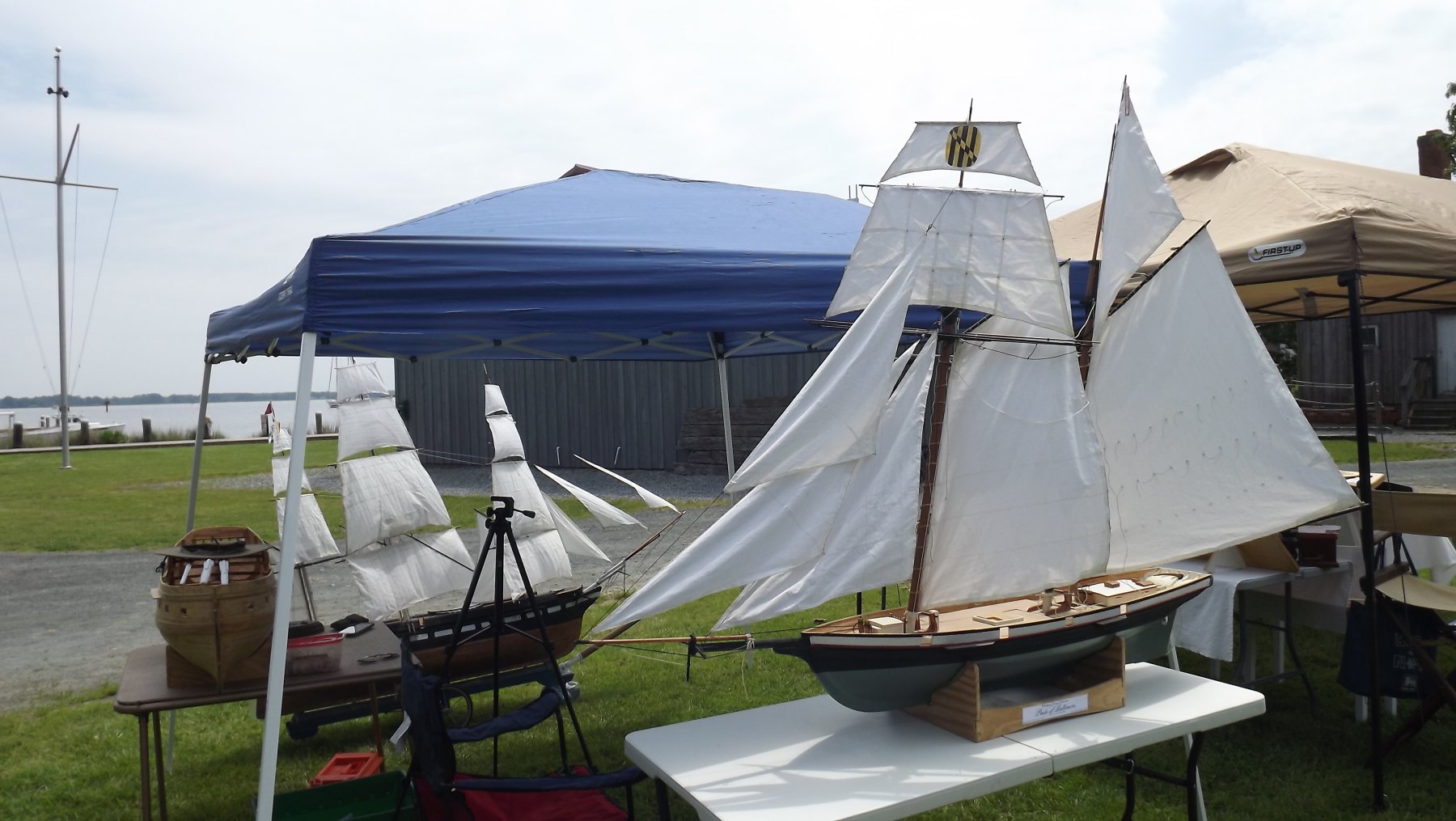
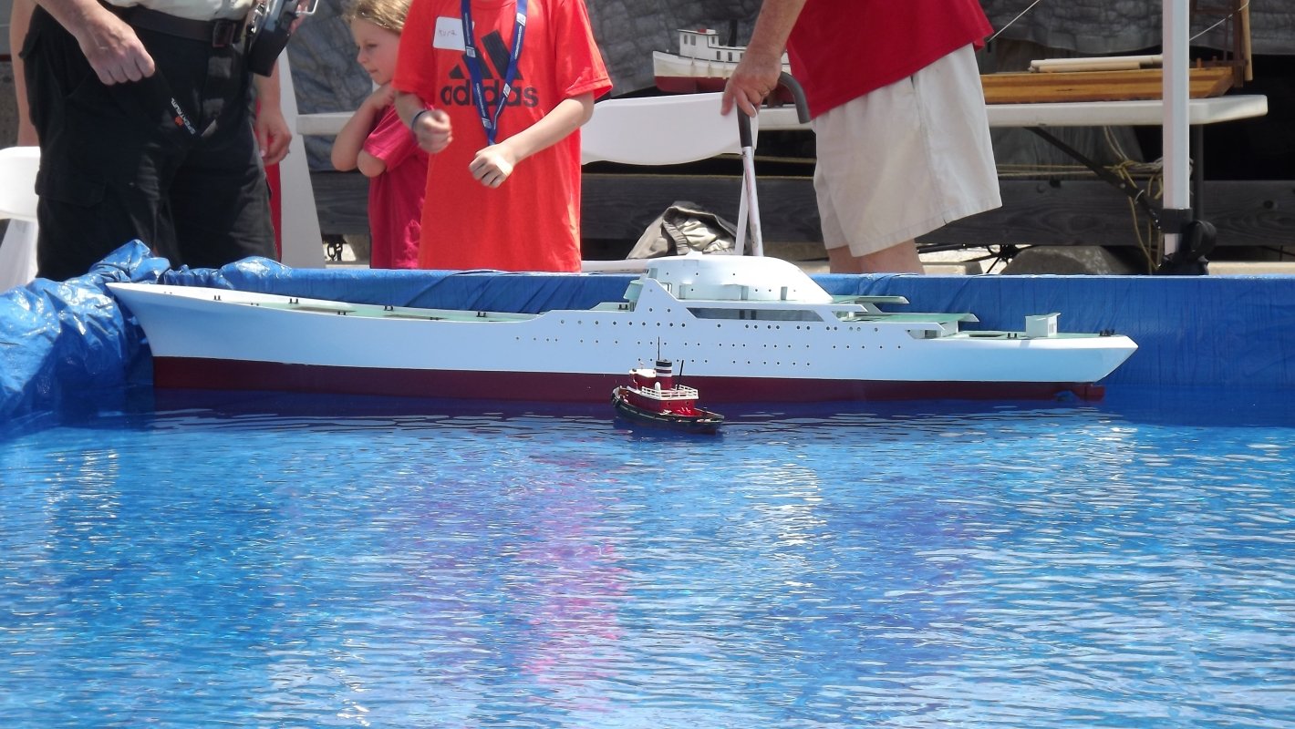
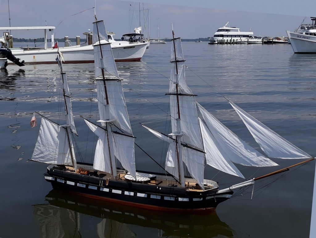
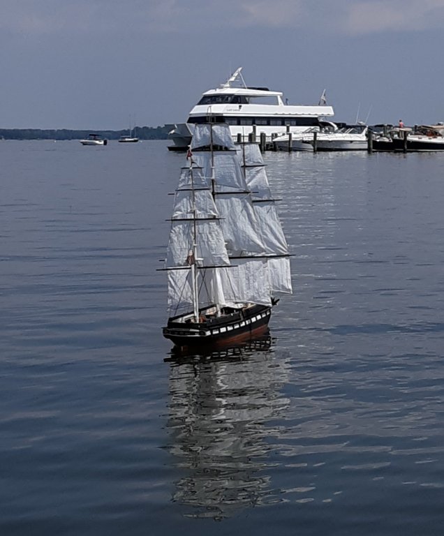
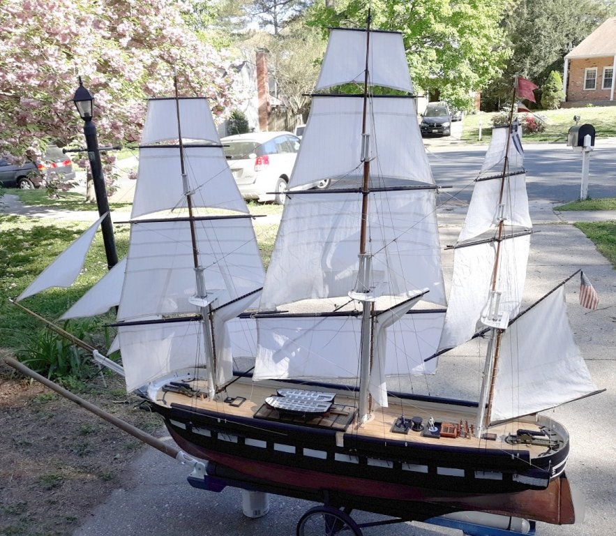
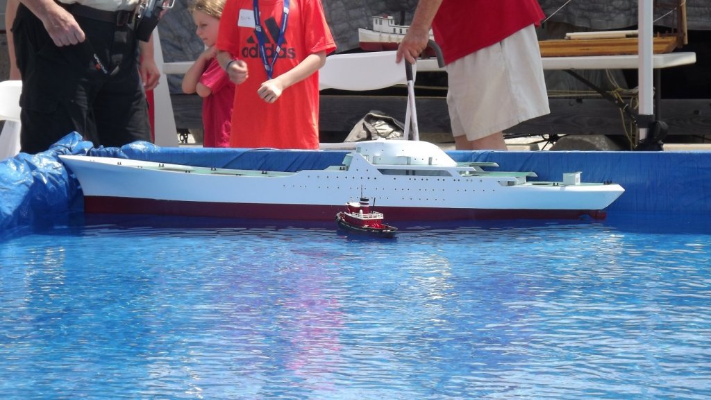
 Pride got out of the house and put on display at the Chesapeake Bay Maritime Museum on Saturday, and at Baltimore's National Maritime Day Port Expo on Sunday. Both events were slow, so I decided to get some pics of the model in the pool, when she started sailing along...

- 79 replies
-
- 4
-

-
- pride of baltimore
- privateer
- (and 3 more)
-
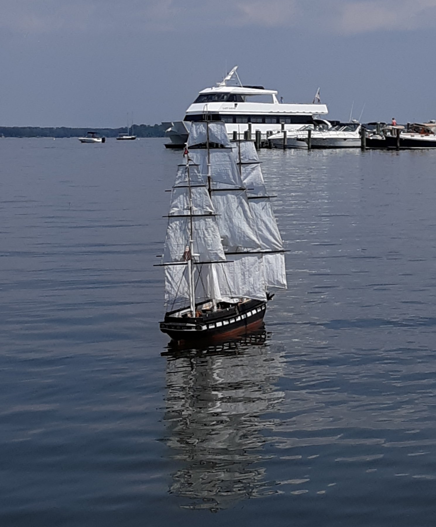
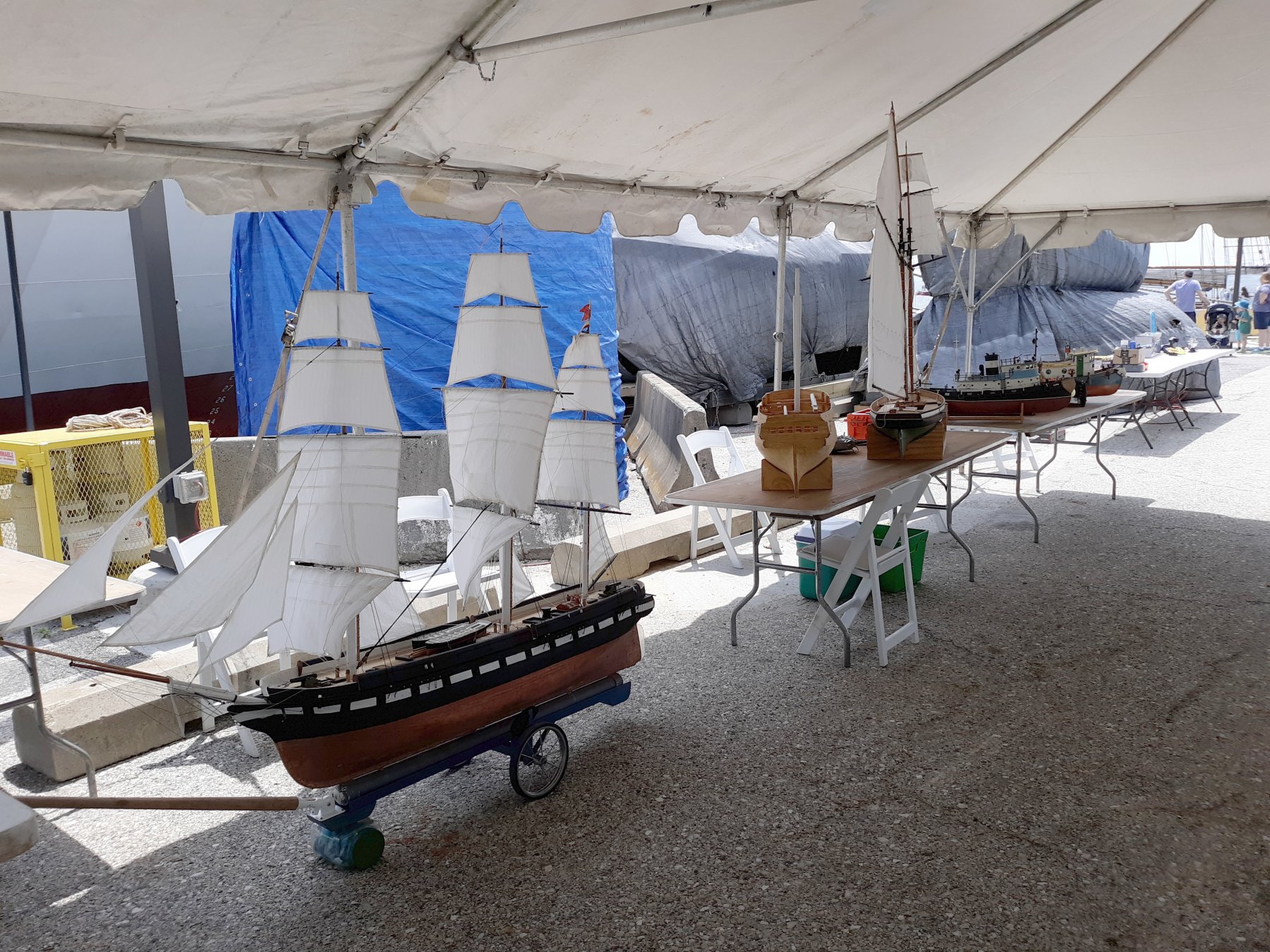
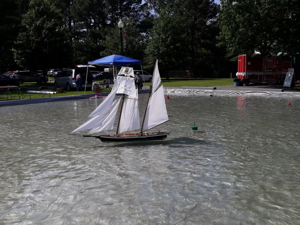
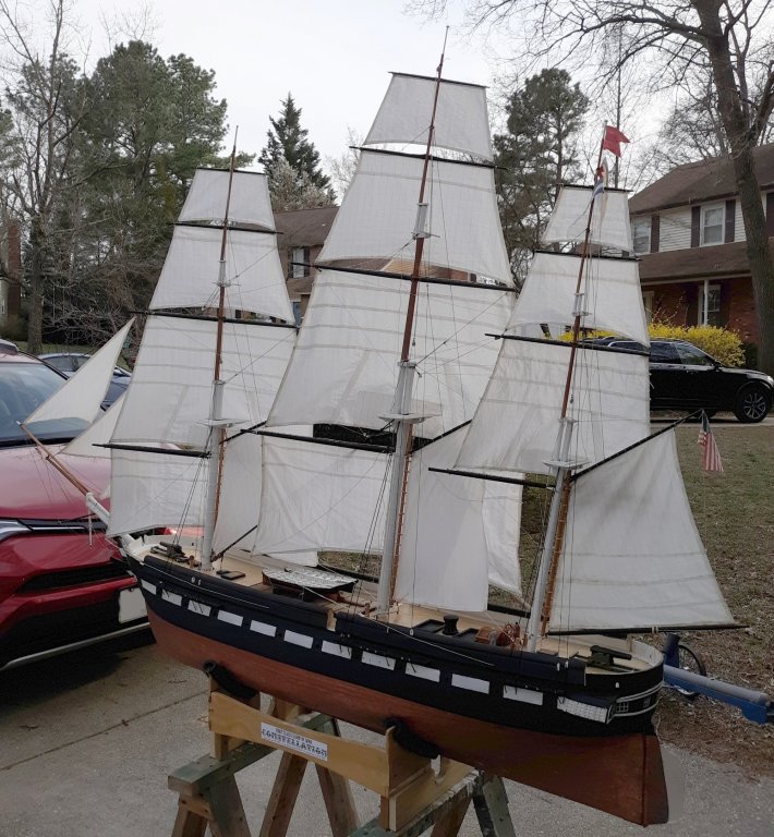
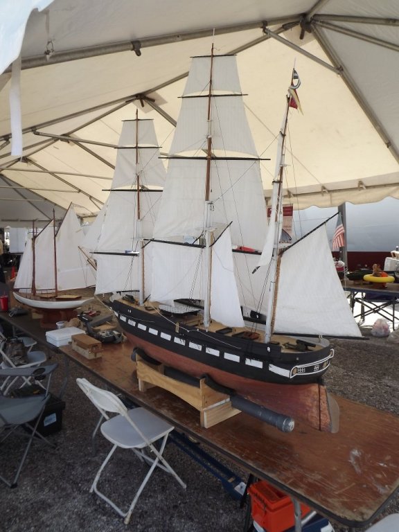
I rented a UHaul trailer to transport the model to the Chesapeake Bay Maritime Museum on Saturday and Baltimore's Maritime Day Port Expo on Sunday. Visitor turn out wasn't very good at either event despite the great weather. There wasn't good access to the Miles River for a model like Constellation, but I gave it a go none-the-less... The wind was all over the place because of the docked boats, and it was tight between the piers, but she sailed. At Baltimore it was very windy, so the models just stayed on the tables.


- 553 replies
-
- 3
-
-
- sloop of war
- constellation
- (and 3 more)
-
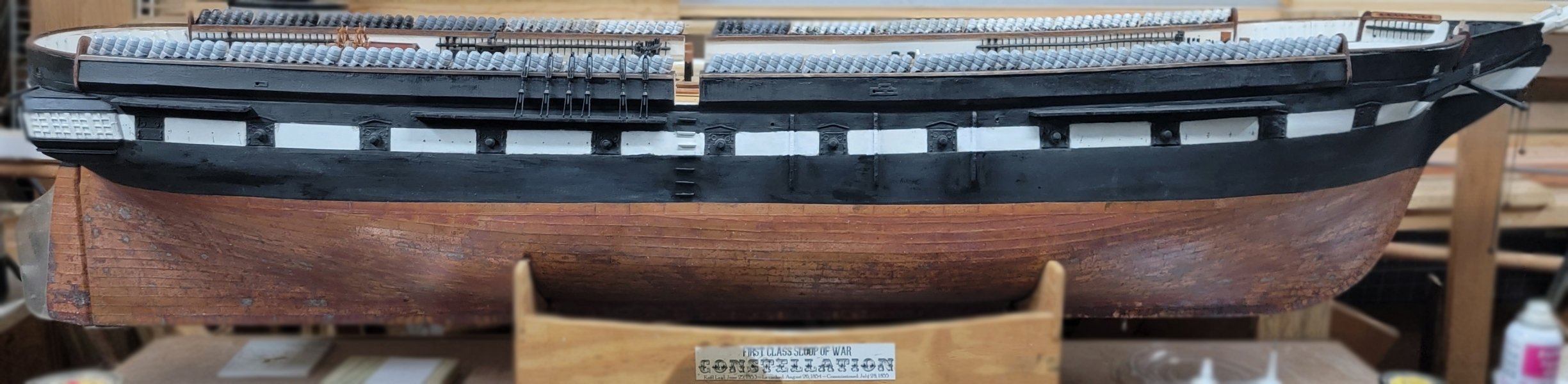
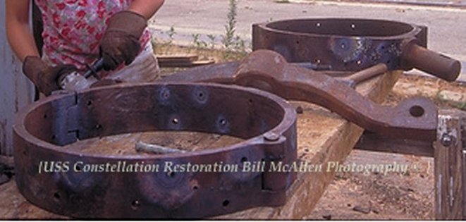
She had the 10 inch pivots when she left Boston in 1859 to post to the Africa Station, but the captain decided she felt top heavy, so they took the guns off and took on more ballast. No mention of taking off the circles. She returned from Africa and got the 20 and 30 pound Parrots in place of the shell guns. I doubt the circles were touched. She went to the Med in 62 and the pivot guns are mentioned during that trip, When she returned in 1864, she became a receiving ship in Norfolk and the pivots may have been removed then or her next refit in 1871. The only spardeck drawing in the National Archives is from the 1886 refit, and there's no trace of gun circles or any guns on it at all.
- 553 replies
-
- 5
-
-
- sloop of war
- constellation
- (and 3 more)
-
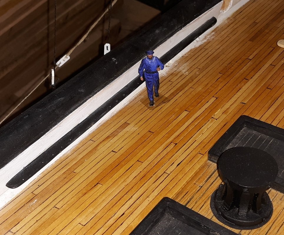
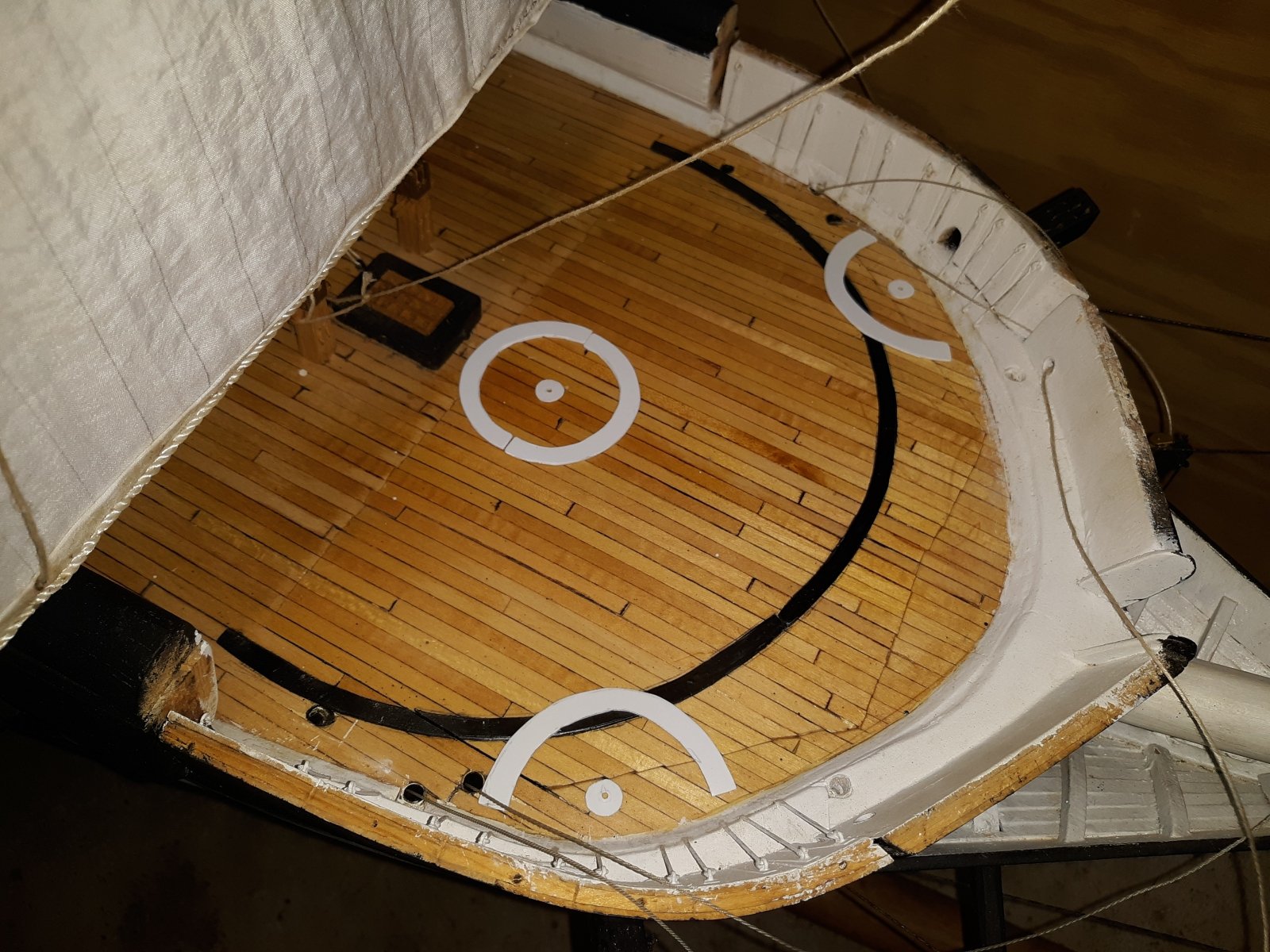
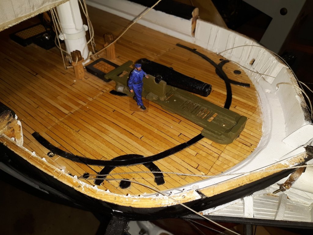
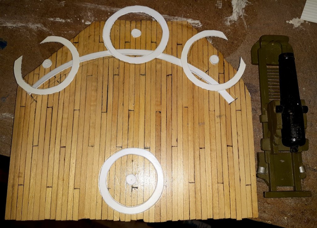
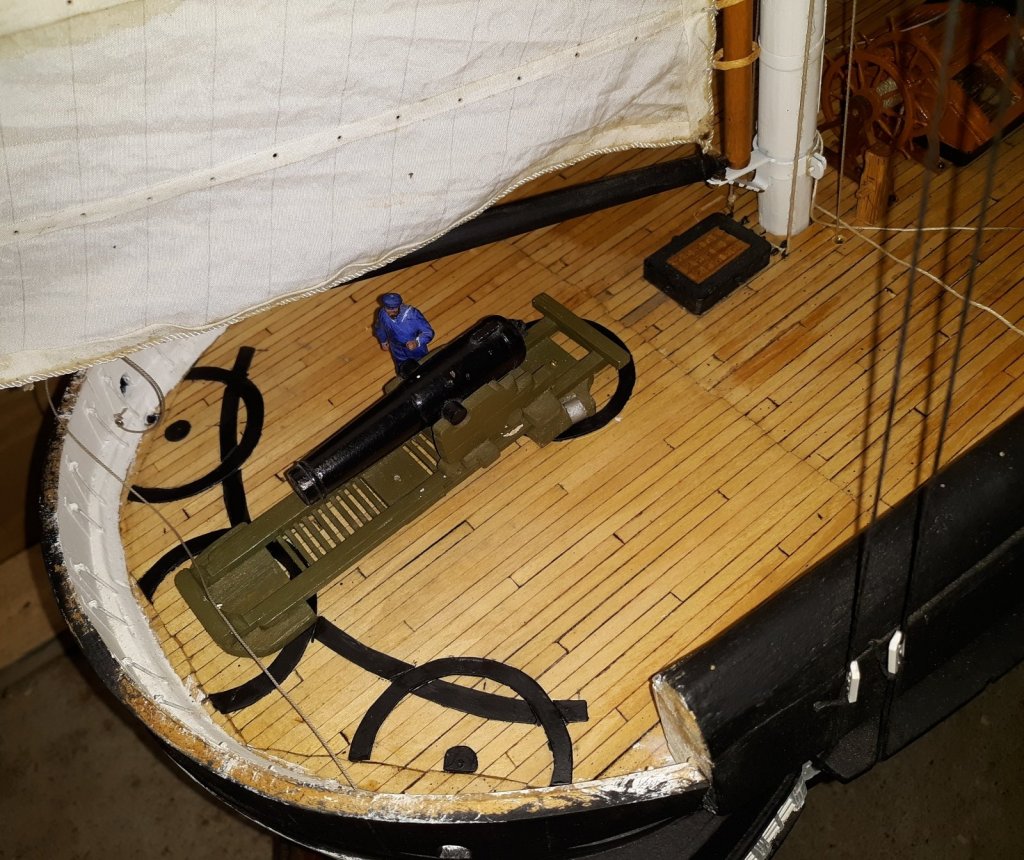
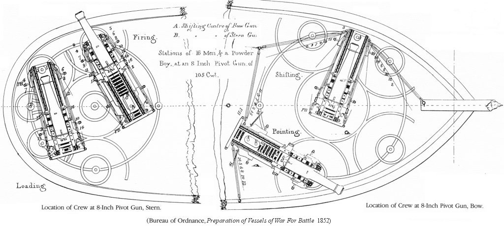
Working in fits and starts, as usual, I installed one of 6 pinrails on the bulwark. This was made from 1/8" aircraft plywood. I'll have to come back to that. Then I put on the "iron" deck rings for the pivot guns. They're made from 1/32nd styrene and CAed to the deck. The pattern of these rings on Constellation is debatable. The museum folks say it was just a single circle for each gun, but in tracking them down, I've found no data yet for Constelation and most other ships have something more than a single circle, especially larger vessels. Since these tracks are often referred to as "gun circles," I think the museum folks interpreted that as a single circle. I opted to model something a bit more complex along the lines of the diagram in the Navy's 1852 manual: Preparation of Vessels of War for Battle. Bow circles... Stern circles...


- 553 replies
-
- 4
-
-
- sloop of war
- constellation
- (and 3 more)
-
I have a blocked fairlead that some epoxy got into. I put some acetone in it, but I haven't been able to clear it yet. Mean while I set the sails, and brushed and vacuumed the winter shop dust off.
- 553 replies
-
- 3
-
-
- sloop of war
- constellation
- (and 3 more)
-
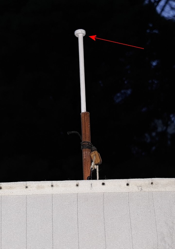
A nice 60° today, and after working of other people's stuff, I got some time on Constellation... Installed the trucks on each mast, made from slices of a mahogany dowel. Also finished installing the hooks on the mizzen t'gallant and royal as described back in #373


- 553 replies
-
- 1
-
-
- sloop of war
- constellation
- (and 3 more)
-
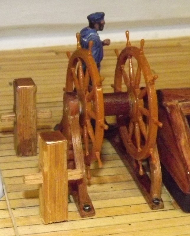
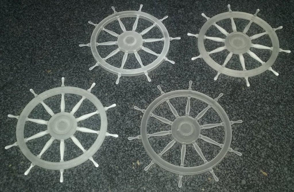
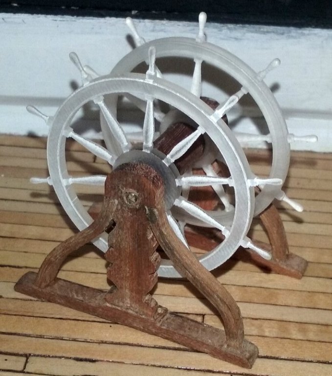
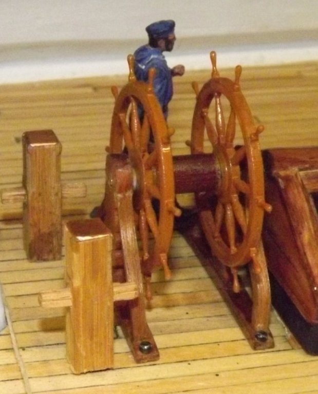
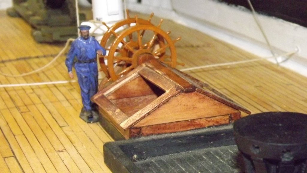
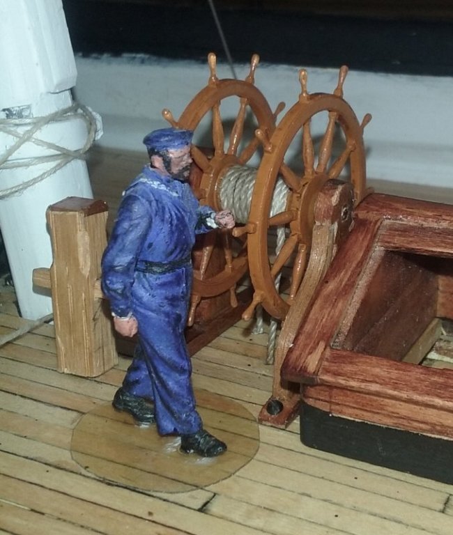
There's a mountain of "little" things that need to get done, such as; gunport eyebrows, boarding steps, galley stack, bow carvings, cat head cats, and the ship's wheel, just to mention a few. Well, the ship's wheel can almost come of the list... I've been trying to turn spokes for the wheel, with no success. There's 20 of them needed and making one is maddening enough, much less replicating it 19 more times. Then I have Macedonian's wheels, and hopefully another single for Gazela Primeiro - that's a LOT of spokes! So I cheated, at least if feels like I have, but hey, maybe down the road I'll figure this out, but until then, this works. I asked Model Monkey via Shapeways if he'd scale one of his ship's wheels to 1:36 scale, just the wheel. He did, and I bought 4 of them; 2 for Constellation and two for Macedonian. A few days later I had them in my fat fingers... They need a helm, or wheel-stand, which I felt I could make without ordering then in 3D - which is still quite expensive. These are mahogany. The curved braces are laminated 1/32" thick strips from a kit, the upright from some scrap left from a musical instrument a friend built. The drum is a bit of mahogany dowell, also left from a kit, with a bit of brass rod as an axle. A bit of paint and some clear-coat and it's just about done. I was going to make it operate when the rudder was moved, but I'm afraid it's too fragile to be spun back and force all the time, the servo moves a bit faster than "scale speed," so I just wrapped some line around the drum and fed it through the deck. The helm is held to the deck with some round-headed wood screws. I lost a spoke handle while painting, but I have some brass belaying pins that are a good match and will replace it with one of those. That's pretty much what cancelled making it operate.

- 553 replies
-
- 3
-
-
- sloop of war
- constellation
- (and 3 more)
-
I don't see that they have CV joints specifically, but when I look for joints I usually look first at Dumas.
- 1 reply
-
- 2
-
-
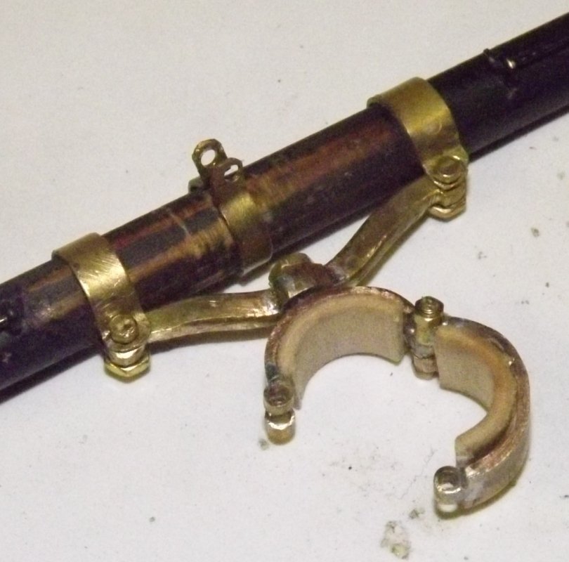
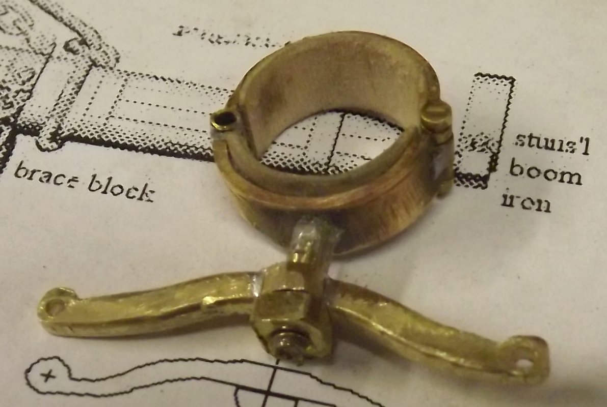
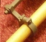
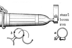
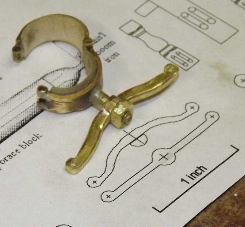
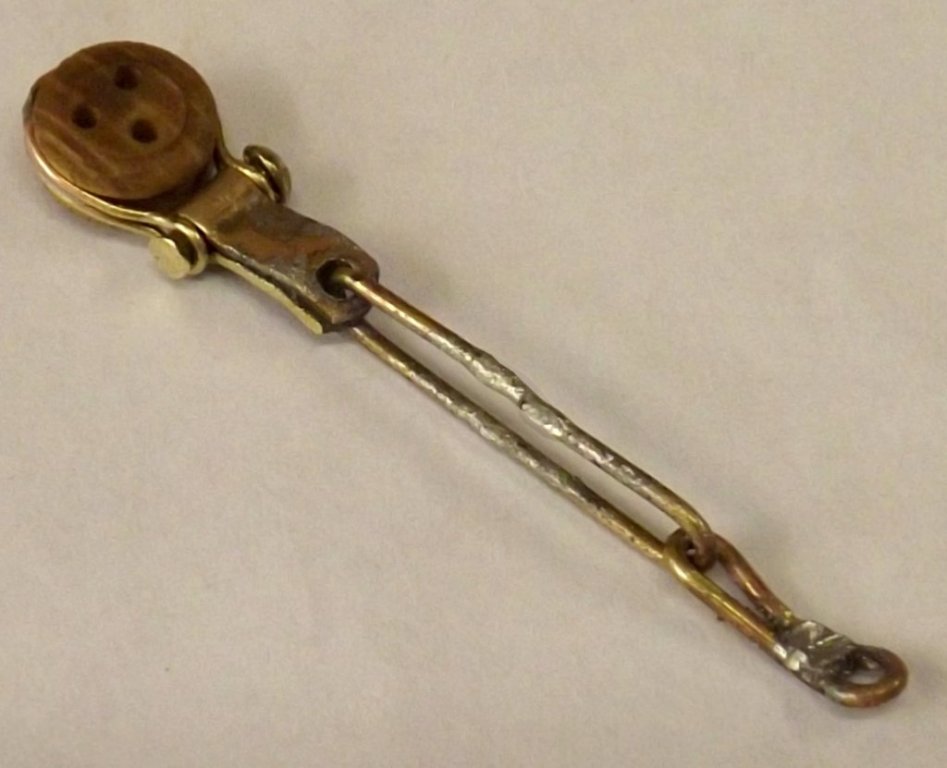
I'm looking at making the stuns'l boom hardware on the yards. The end cap and post, referred to by Luce as a Pacific-Iron, isn't to difficult, but the iron that sockets onto it is another matter. Sometime back I saved an image I found where someone made them, but I don't recall who, what model, scale, etc, but they are exactly what I need to make, though I have no idea how. I could make a master and cast it in resin (I need 12 of them), but I don't think that would have the strength, so it's going to be a sheet brass and rod affair. (3d printing is so far above my income bracket as to not even be considered). I have an idea of shaping a long narrow strip of brass or copper sheet and soldering it at the "post" between the socket and the hoop. I could solder a bit of rod as the roller or even use some tube and run a pin through it. looking at the bottom of the fitting
- 553 replies
-
- 3
-
-
- sloop of war
- constellation
- (and 3 more)
-
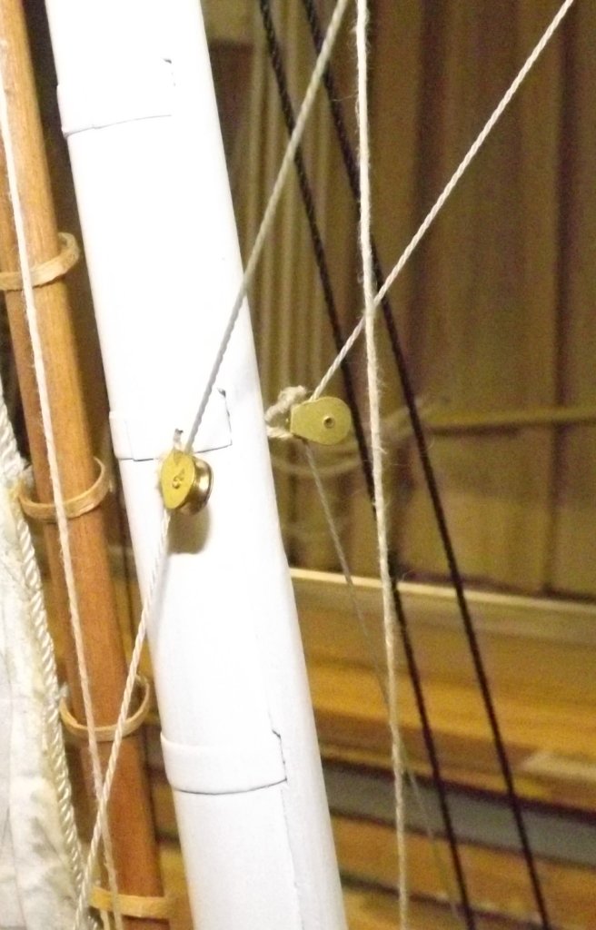
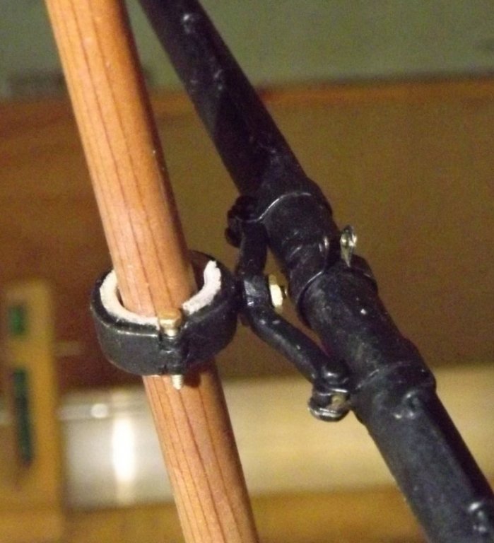
Regarding my obsession with that thing the main tops'l brace ties to, I found the following in the 1891 edition of Luce's Seamanship. Main-topsail Braces. Standing part hooks to an iron traveler, which moves up and down the mizzen topmast to shift the strain lower down as it becomes greater (if the mizzen-topsail is reefed or taken in), thence to the yard and down to hanging blocks on the mizzen-mast, about half way between the top and the deck. Earlier edition's of Luce's I have PDF's of (1863, 1868, 1877) have the braces hitched to the mizzen topmast head and seized to the stay-collar, or they might lead through thimbles at the mizzen topmast head and down to the chains, but says many ships now do the above. At any rate, there's some documentation verifying what I was seeing in the photos. Personally, I like the thimble to the chains set-up myself, as it would give me a really nice way to incorporate a way to make adjustments, but that's not what the ship had, so... Until I get a better notion of what was this part actually looked like, I made a jib-hank looking thing for the time being. I also put eye's into the mizzen mast for mounting the "span-blocks" here shown with brass blocks temporarily installed. Here's a link to an exciting minute-and-a-half of video showing the tops'ls braced by two separate winches - except the mizzen which wasn't rigged yet. Please excuse the main canting and such, it's actually not fully hoisted there.

- 553 replies
-
- 2
-
-
- sloop of war
- constellation
- (and 3 more)
-
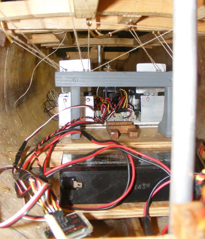
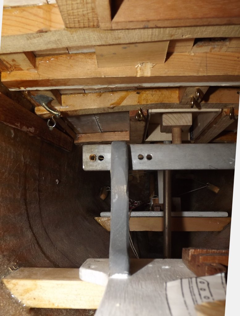
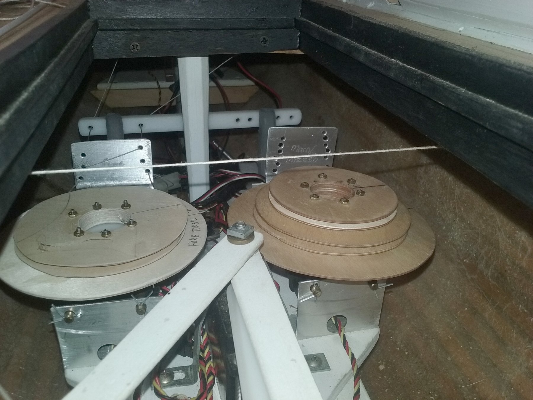
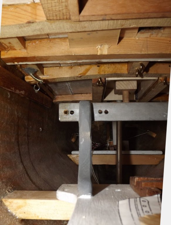
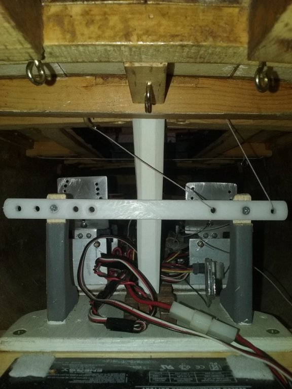
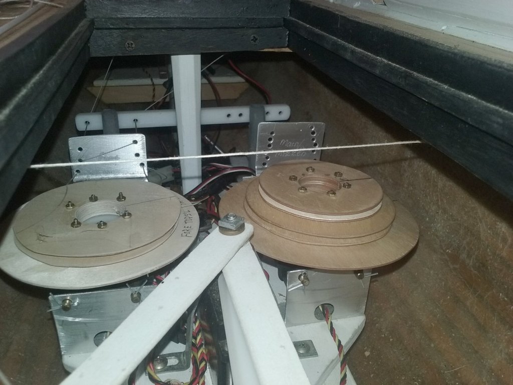
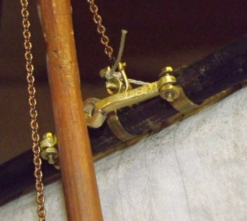
When the sliding winches went in, so did a structure that looks like a riding bit, or a hitching post that served as a fairlead bar for the braces. Each winch has a fairlead plate attached to it to guide the braces onto the correct winch drum, but if the braces diverge as they leave the winch, it'll prevent the winch servo from sliding fore-and-aft to maintain tension on the braces. This fairlead bar directs the braces straight aft to prevent that binding. Initially that "bar" was wood with eyes on top. That was replaced with a metal bar with holes. Today the metal was replaced with a plastic strip cut from the edge of a cutting board. The foremast braces make a hard turn right here and I may install a couple of blocks for them instead of relying on going through a hole. Original wood bar.. Metal bar... New plastic bar with fore tops'l yard braces run through.

- 553 replies
-
- 1
-
-
- sloop of war
- constellation
- (and 3 more)
-
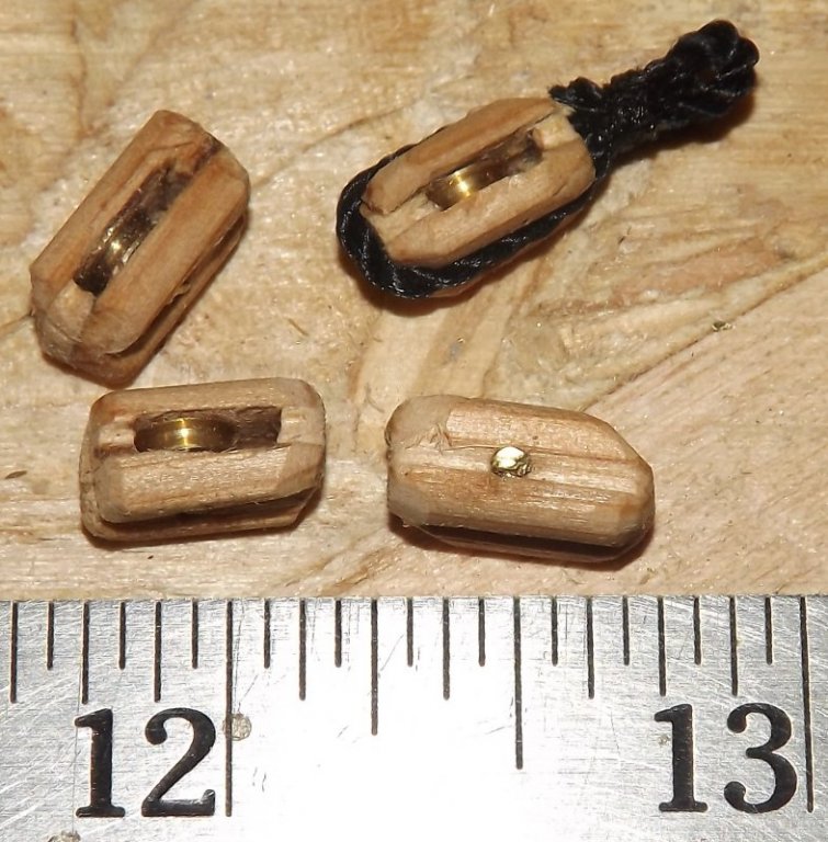
I've been using some brass frame blocks for brace blocks on the yards, they aren't the correct style for the ship, but I needed functional blocks on the braces. I also only have so many of them, so to free a few up for duty below deck, I made up 6 functional wood-shell blocks for the braces. They're ok, and they work, but I don't care for how they turned out. I used some white cedar for the shell, which is too soft and open-grained. I have some branches from a fruit tree, though I don't know what fruit, and I'm going to try and mill some of it to use for blocks. Till then, these will do.
- 553 replies
-
- 4
-
-
- sloop of war
- constellation
- (and 3 more)
-
Making the mizzen parrel has all three sets of parrels and trusses done save for painting. and the real thing...

- 553 replies
-
- 4
-
-
- sloop of war
- constellation
- (and 3 more)
-
Vic, you could bend poly that way, with maybe a 6" diameter bend at the top, since it's not going quite 180°; and instead of any framing, just cement the ends on. Use a heat gun like you would to bend PVC. Careful that you can lift it over the model and it's not too narrow at the base. If you can brace the yards around a bit that could help with that.
-
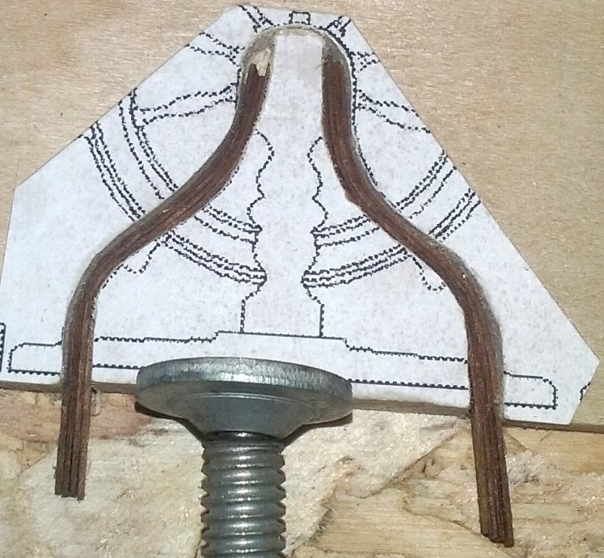
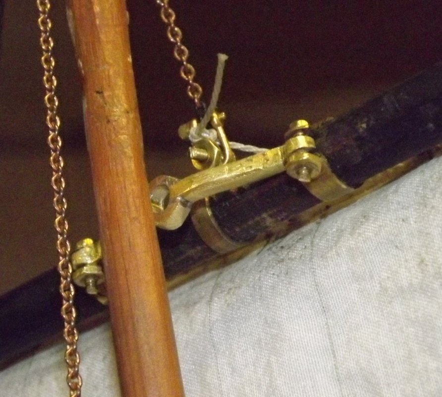
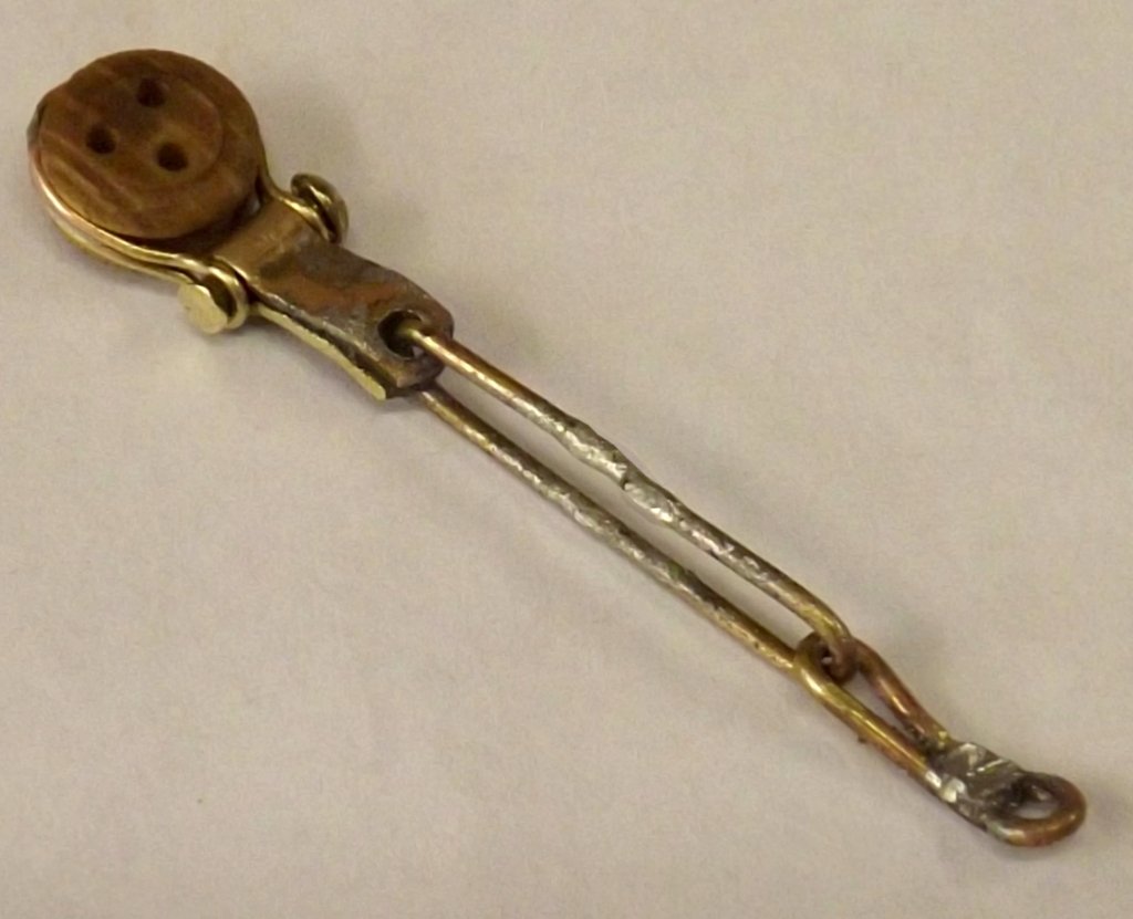
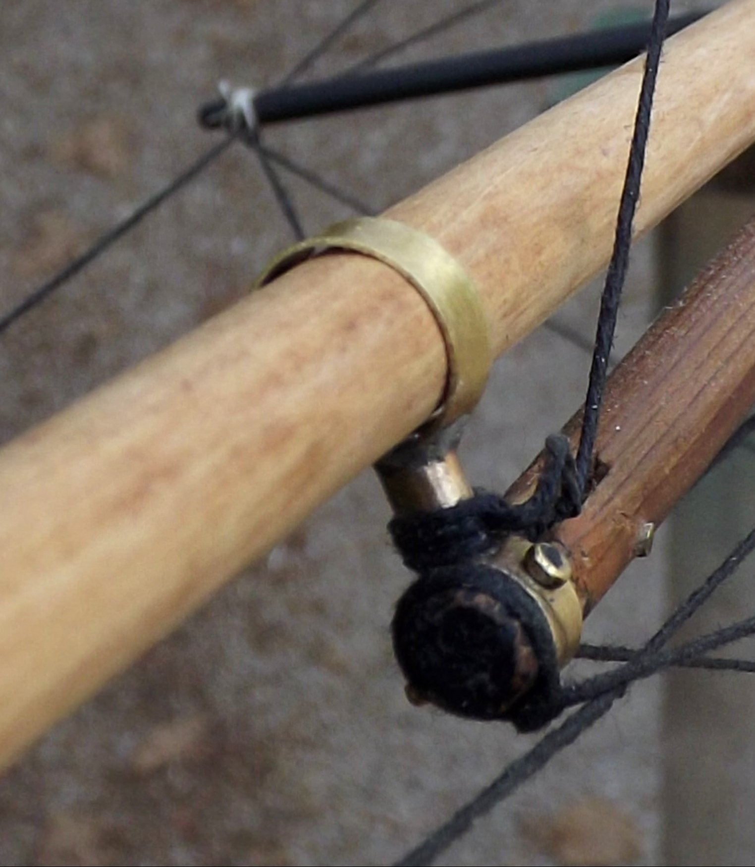
I spent a couple of hours making a yoke or bow, for the fore tops'l yard. This is the thing that attaches to the yard and connects to the parrell. The main tops'l yard's and all three lower's were made from aluminum, but the last one took three tries to get and came out, well meh. I'll never claim to come near the metal work seen in this forum, but it's functional and I do get better little by little. I tried a different idea in their construction this time, since my soldering's gotten better. I cut some brass rod and hammered it square, or mostly square; then bent it to the right shape as my pattern. I hammered the ends a bit more to widen them and used files to shape them. I cut a notch down the middle of some rod about double the diameter of the first one, then cut off about an 1/8" giving me two half-round pieces. These got soldiered top and bottom to the center of the bow, forming the swell that the parrell pin goes through. After some filing and cleaning up, I drilled the hole in the swell and 1/16" holes in the ends. Then something happened with the drill press that startled me, I jumped, and the part flew off somewhere. I spent the day "cleaning" the shop trying to find it with no luck. So tonight I did it all again, but with some hope of finding the errant part eventually, I went about making the mizzen bow instead. when it came time to drill, I dug out the 2-direction sliding vice thing for the drill press, instead of holding it by hand with pliers, and everything came out fine with no unscheduled flights. The parrell shown is for the fore tops'l yard which is why I was making that bow, I haven't made the mizzen tops'l yard parrell yet. I do need to enlarge the hole slightly because the bow is supposed to go all the way on the post more than shown. Mounted on it's yard, the chain is the tye for the tops;l halyard, and the bit of line is the end of one of the main tops'l yard braces. The little nuts and bolts are 0-80 x 1" hex head bolts I bought 100 of years ago with some matching nuts, and some "scale nuts." I'll never get any prizes for my metal work, but it's functional, gets painted, and looks like the generally like the real thing even fairly close.

- 553 replies
-
- 5
-
-
- sloop of war
- constellation
- (and 3 more)
-
Rings are nothing for someone that's done what you have so far, and I find at scales of 1:48 and up, it's almost easier to actually make netting than a netting like substance, which never looks right anyway. I have a feeling once you nail it down, you'll start building a seine-fisherman just to make the nets.
-
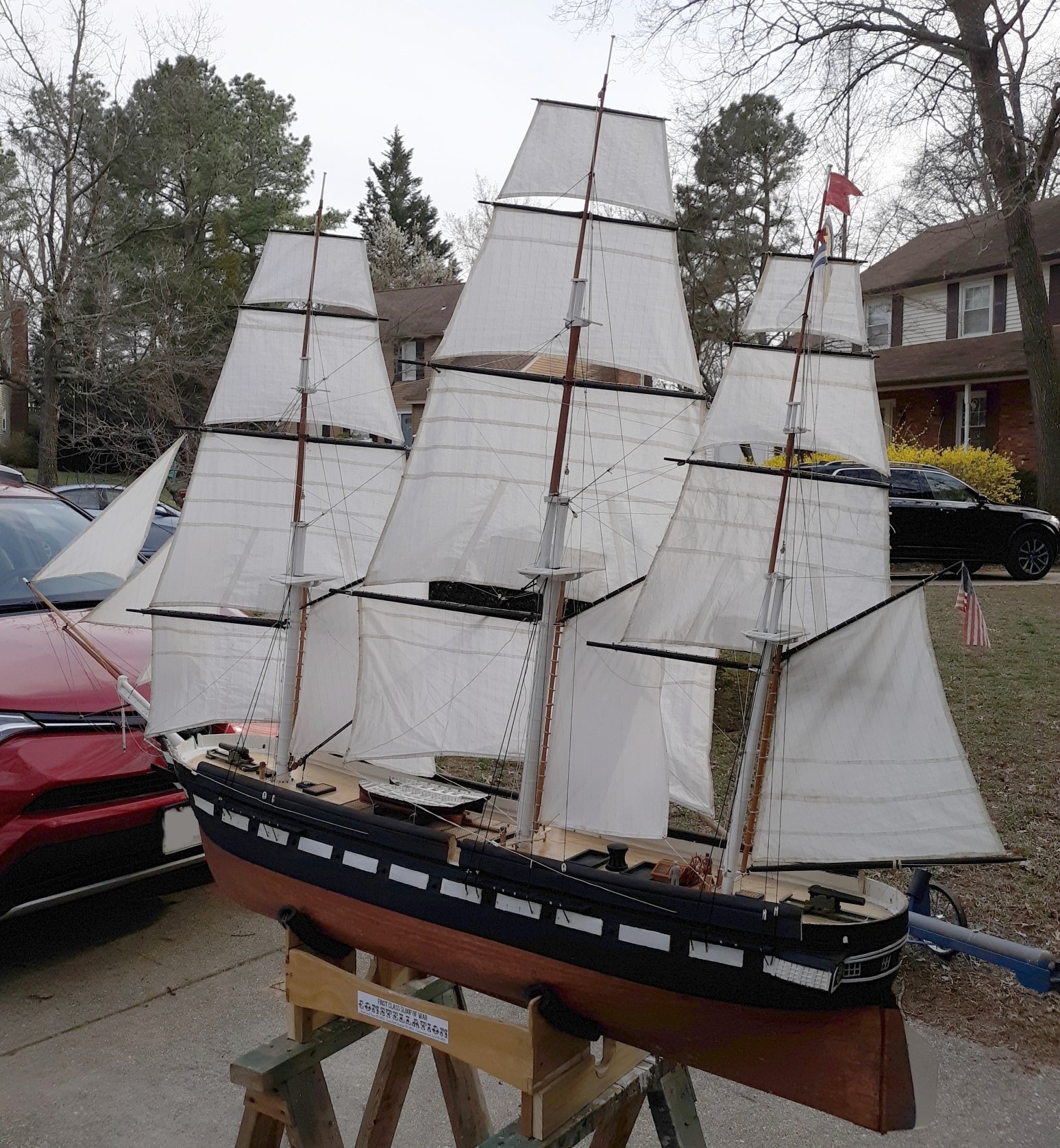
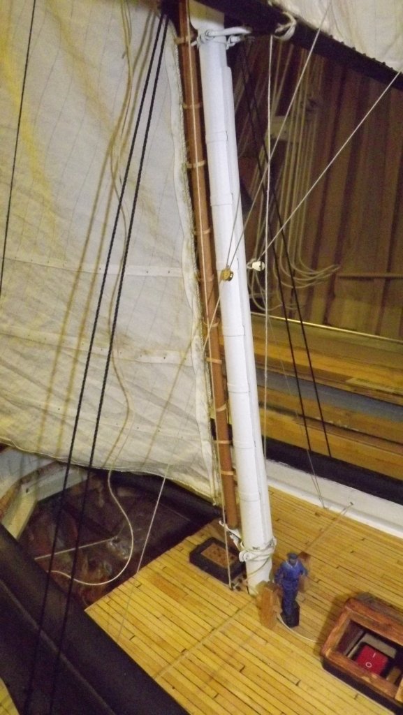
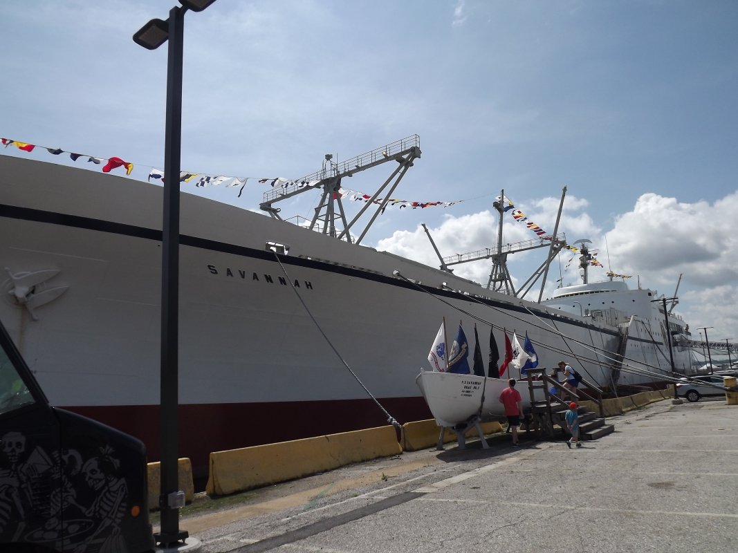
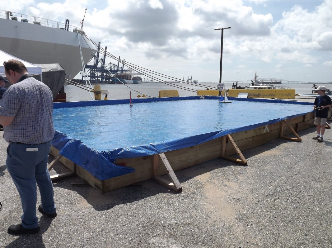
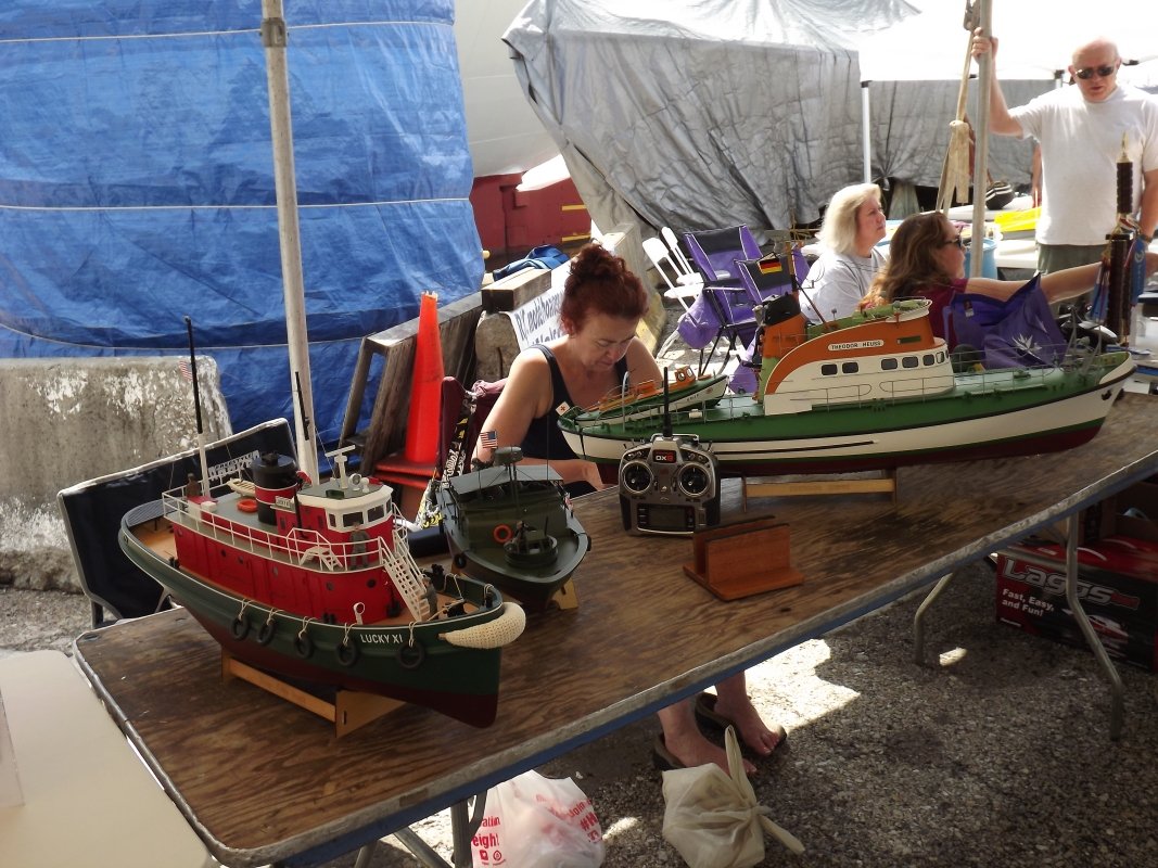
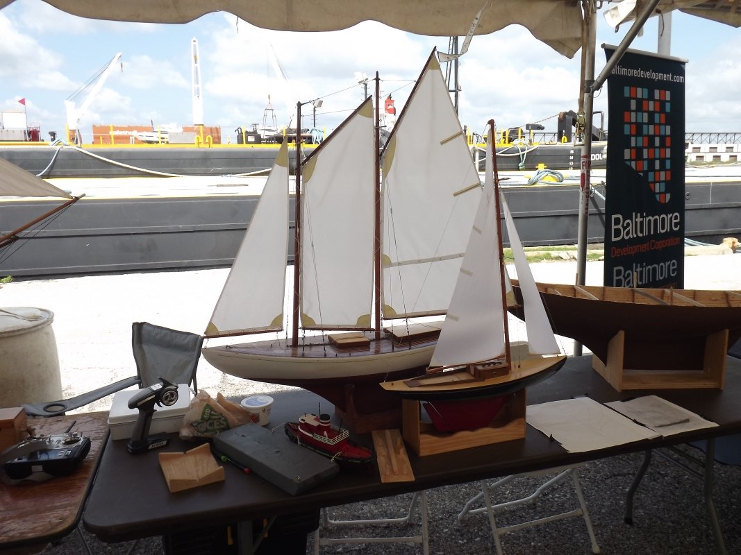
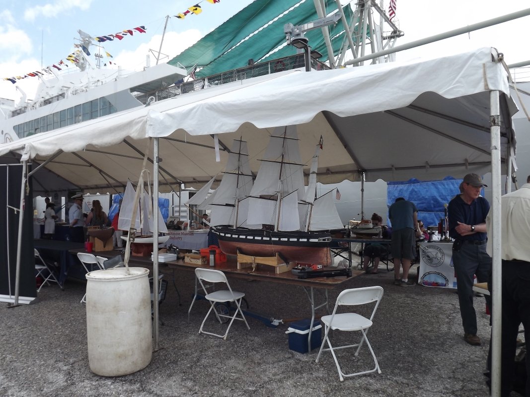
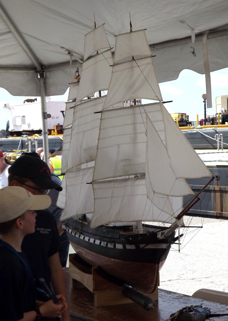
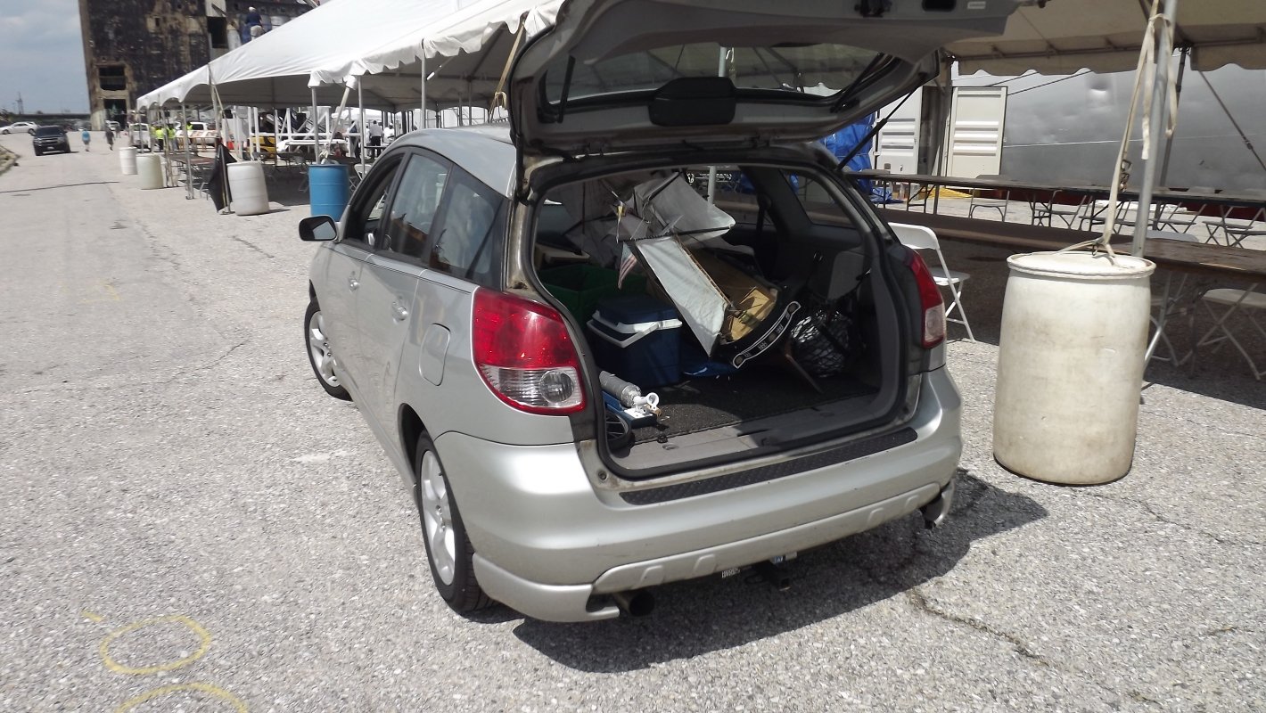
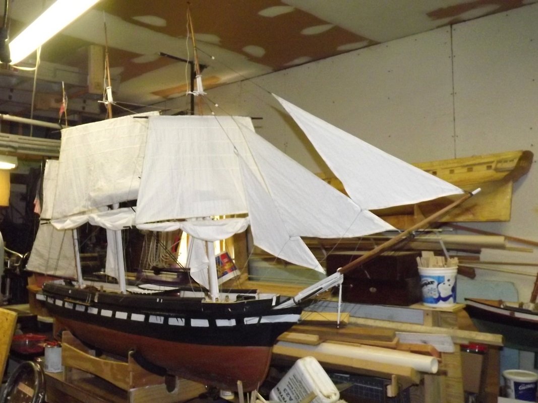
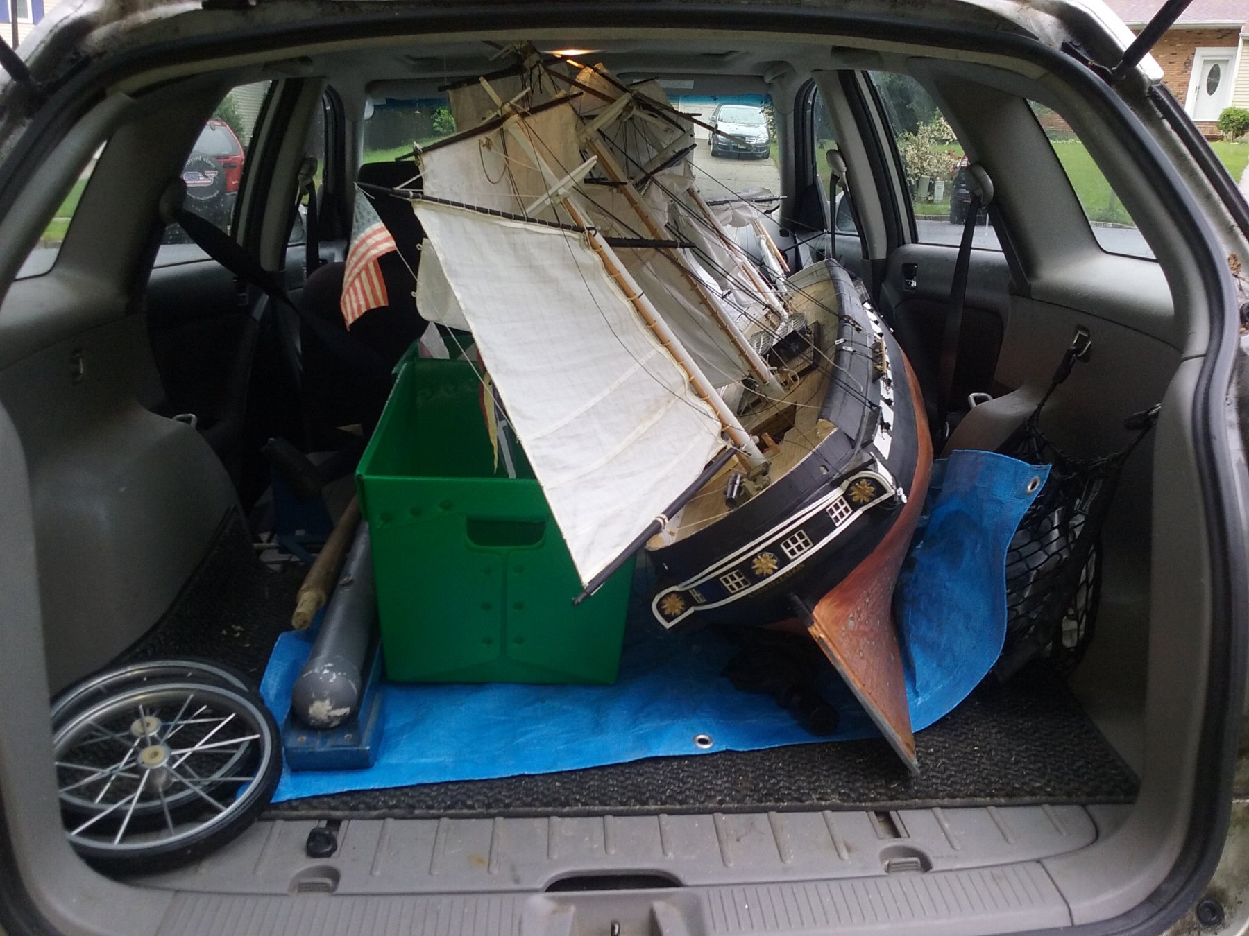
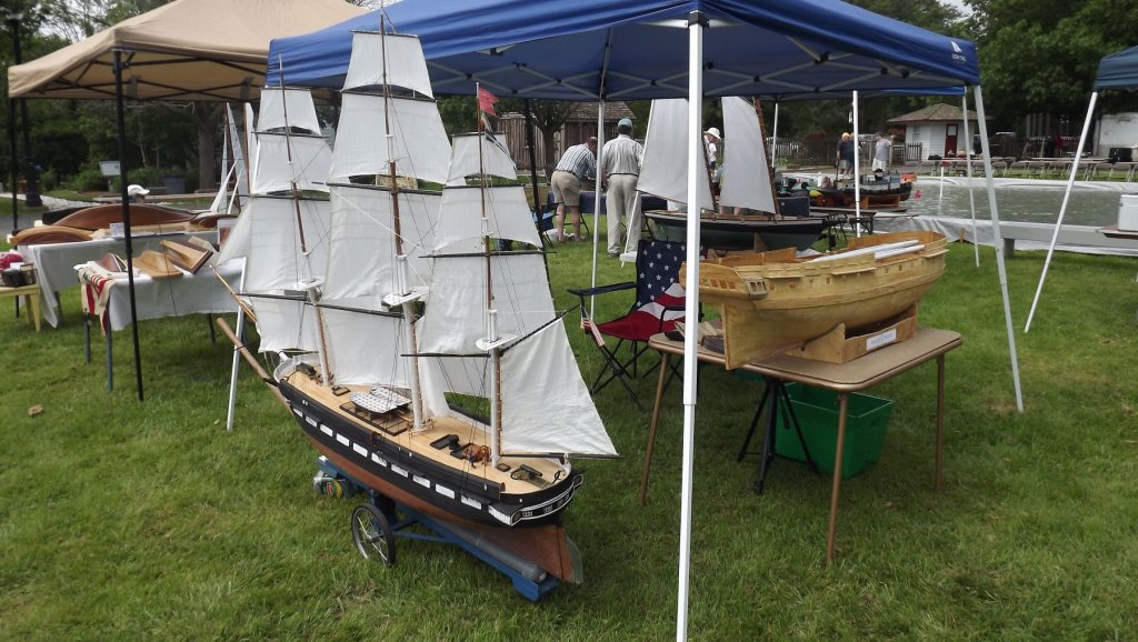
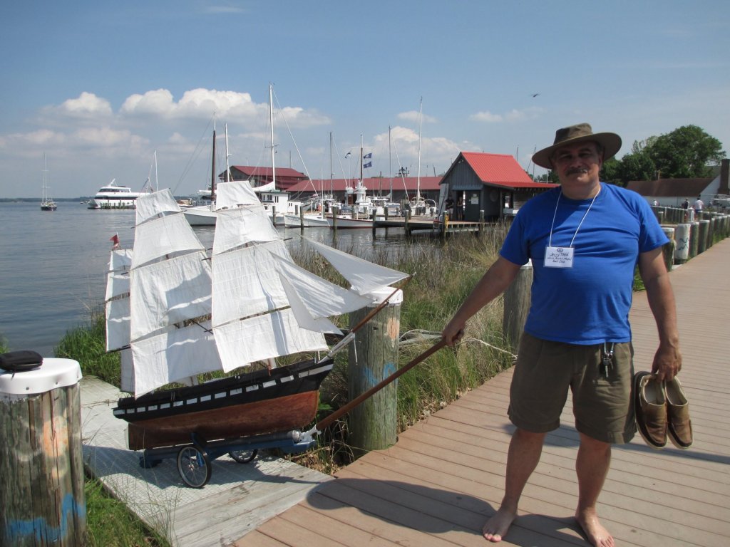
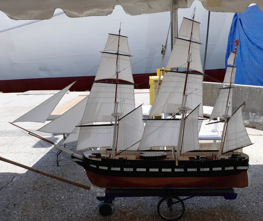
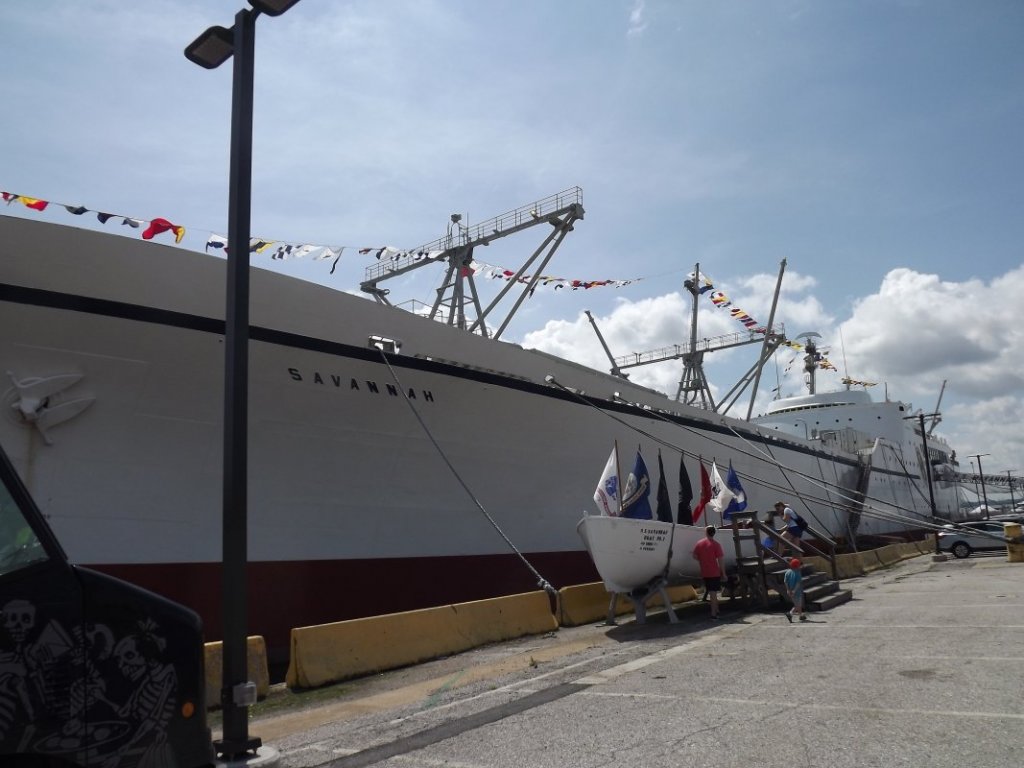
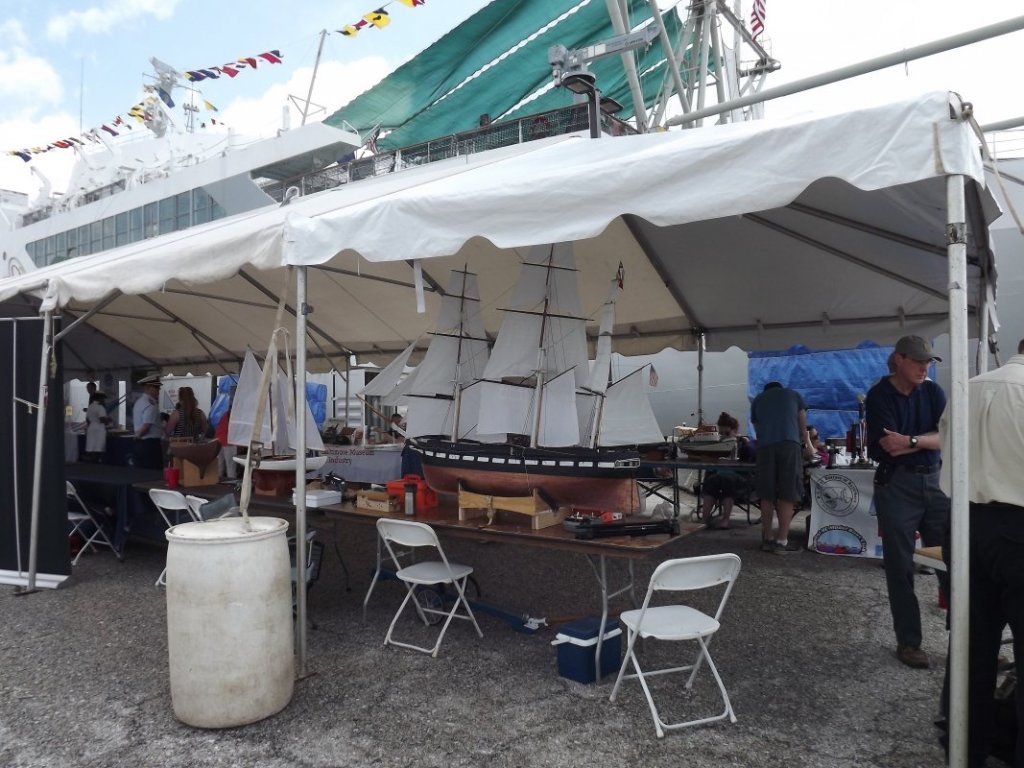
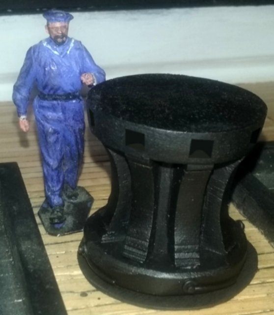
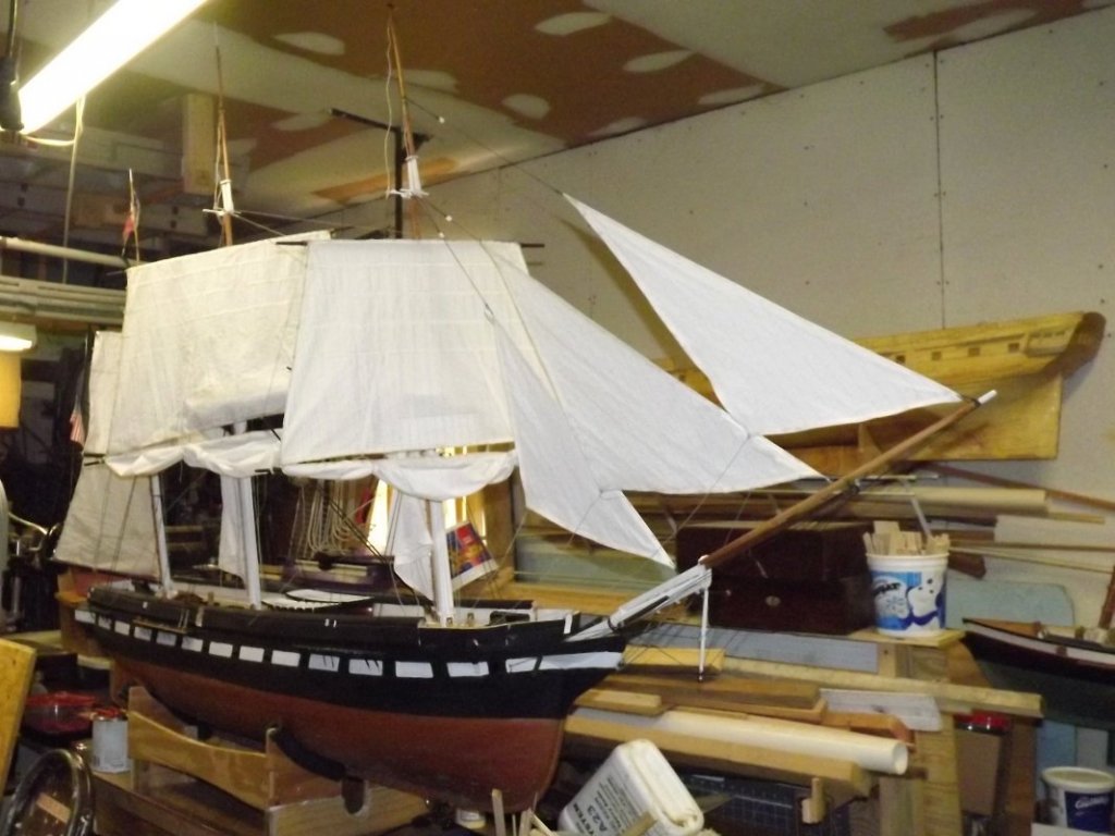
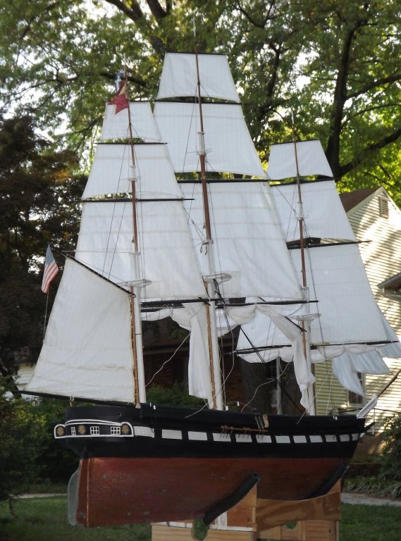
It rained from the 15th through the 19th, monsoon style, and the museum cancelled all their outdoor activities, so I cancelled the trailer I had reserved. So much for sailing. Sunday was much better, weather wise, but I wasn't planning on sailing at Baltimore, the pond's small and there no access to open water. Since our van was traded in and replaced with a smaller RAV4, which is why I was renting a trailer, I only had the Matrix. Only one model would fit in it, and that required reducing the rig as much as it could be. I couldn't even take another passenger. Baltimore's Port Expo is held on the Savannah's dock. They set up a 30' x 40' x 2' pool for the models. Several modelers showed up with their models, and one model in particular got the undivided attention of one visitor. Constellation sat on a table and a few folks stopped to talk about her. Then is was back into the car... Back in the shop, I reduced the rig, but I didn't down-rig her as I hope to take her out for a sail somewhere local in within a couple of weeks. In the mean-time, I made her capstan from a bit of 3/4" maple dowel, and some mahogany from the restored ship's hatch combings.


- 553 replies
-
- 3
-
-
- sloop of war
- constellation
- (and 3 more)
-
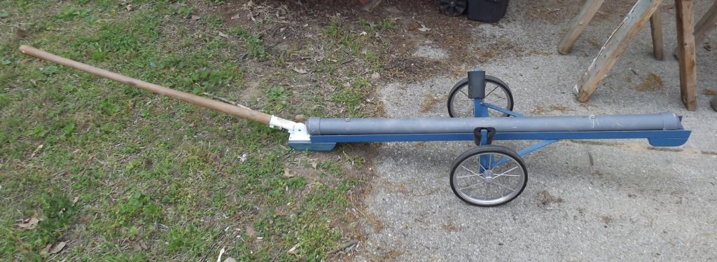
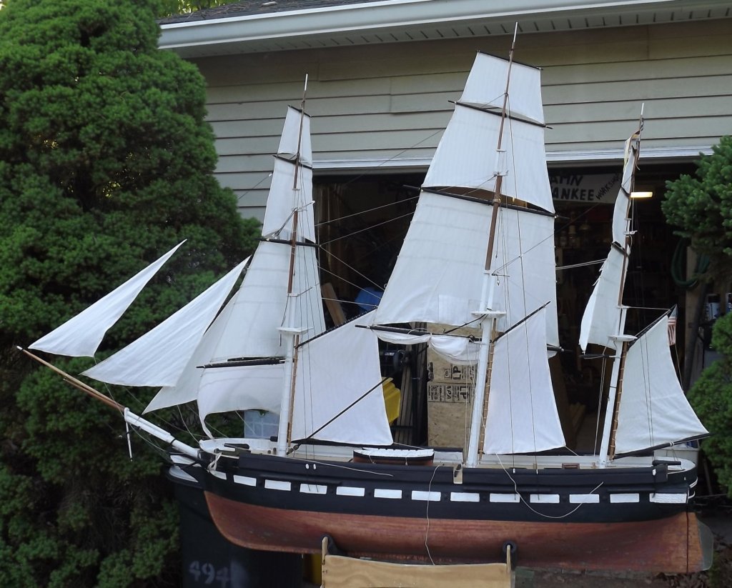
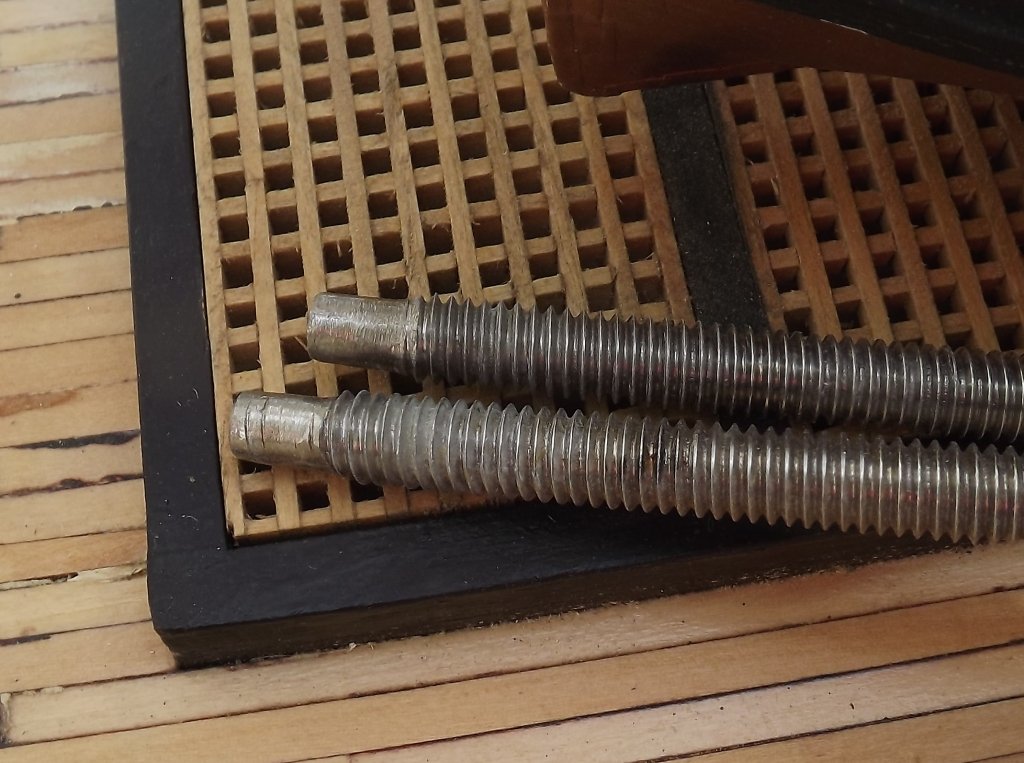
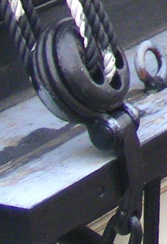
Despite the idea that most of what I'm doing to make the boat sail is temporary, or "jury-rigged" there's some real work going in, and some of the temporary stuff is testing ideas that will become permanent. The wythe (flying jib-boom fitting) was remade with too big a hoop. I remade the hoop from sheet brass to the right size. Finally getting a handle on soldering, I started making the strops for the deadeyes which is doubled over rod. Attaching it to the chain-plate has been tricky. I was using round-head brass escutcheon pins, cutting them to length, and peening them, but they aren't peening very well, and bend more often than not. I'm looking for copper pins hoping they'll peen more easily. As mentioned, I ground off the threads on her keel rods for about 1/2". This has made putting her on and off her ballast tube much easier. To facilitate shortening sail if it gets too breezy, I used hooks on the clews and halyards of those sails so they can be removed entirely fairly quickly. The courses can be clewed and bunted, and the trys'ls brailed up taking the ship from 17 sails down to 7. If it's too windy for that, well, then it's too windy to sail her.

- 553 replies
-
- 9
-
-
- sloop of war
- constellation
- (and 3 more)
-
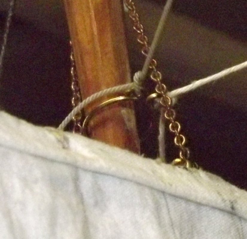
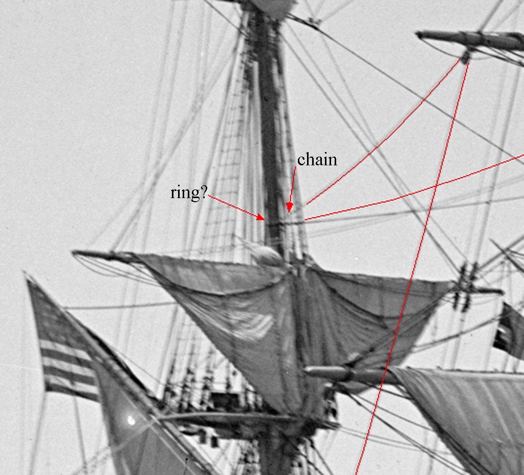
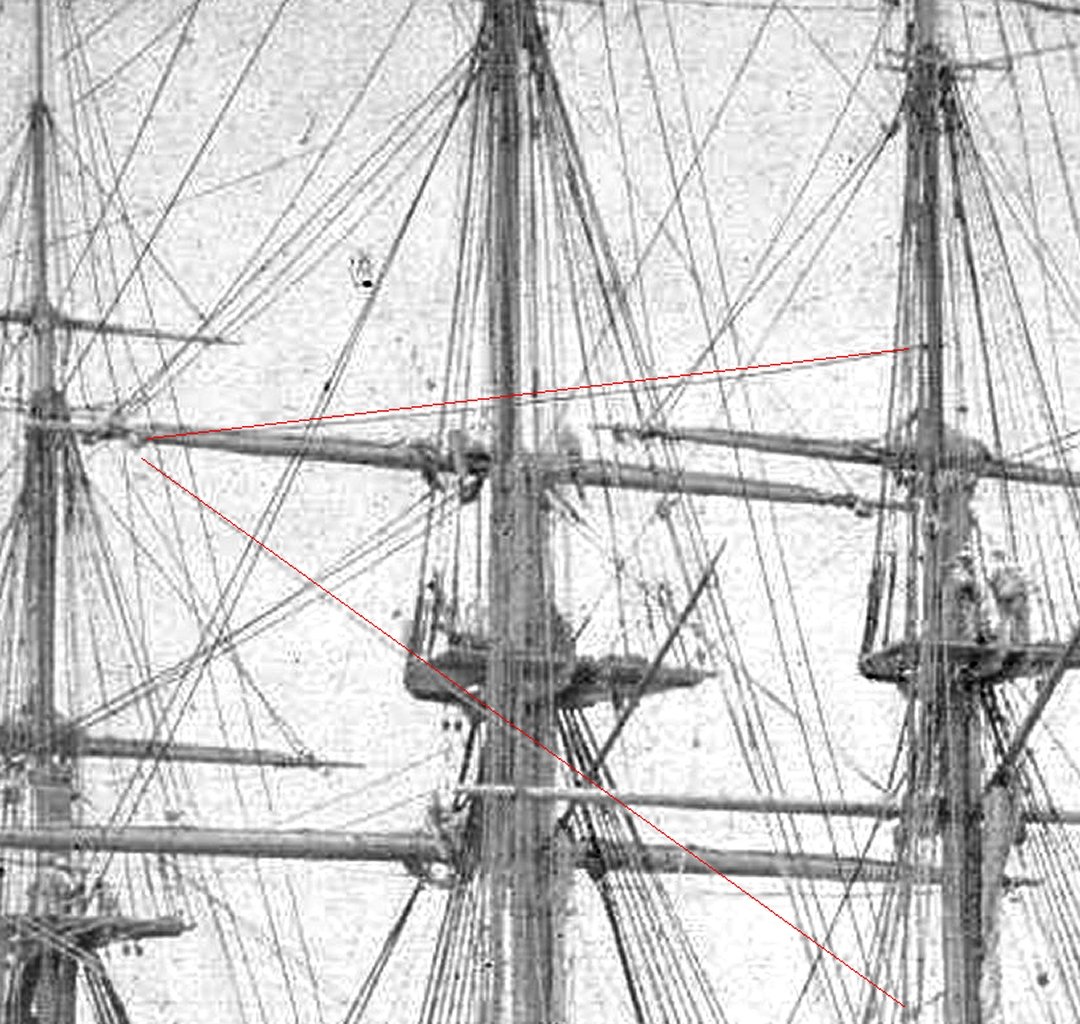
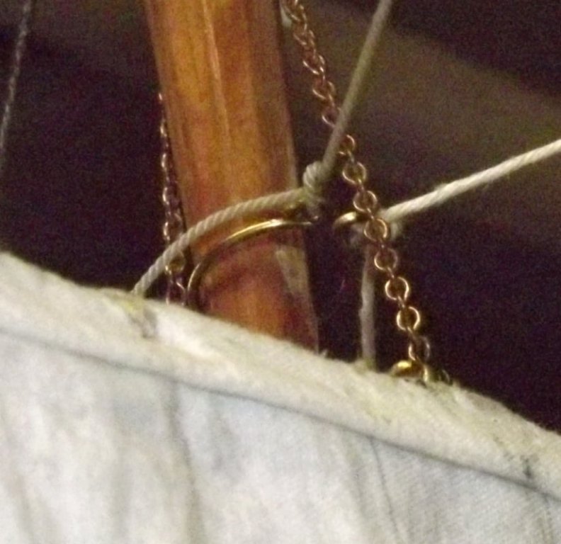
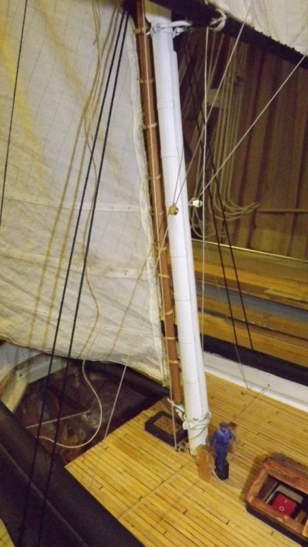
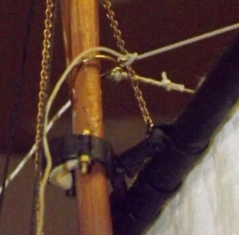
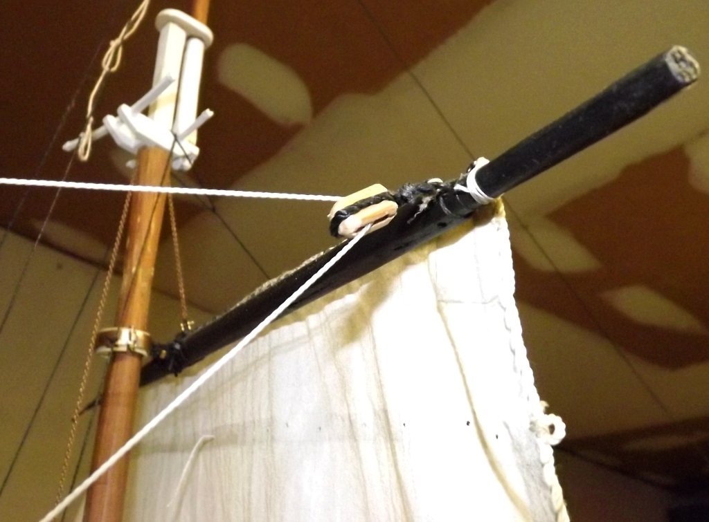
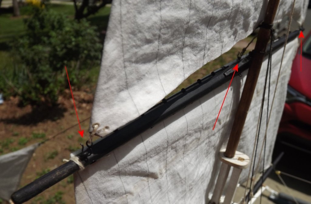
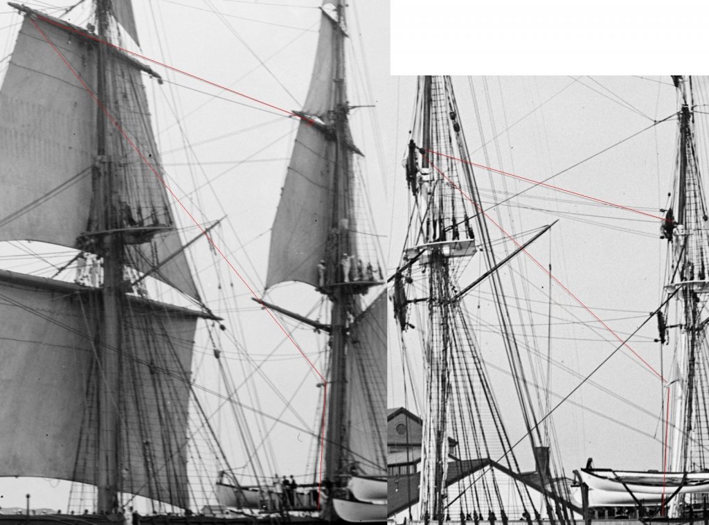
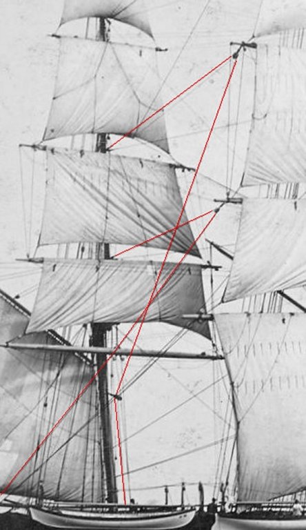
This "ring" is on the mizzen top-mast and is pushed up by the mizzen tops'l yard's parrell as the sail is hoisted. The blocks on the lower mizzen mast are attached to eyes on an iron band. This doesn't interfere with the driver as that is hooped to it's own Spencer mast abaft the lower mast. The idea behind the braces being doubled back is obviously to gain mechanical advantage, but also to make the pull against the yard even, so you're not trying to cock the yard as you brace it, AND so the yard can be raised and lowered usually without having to slack the braces. Rigging, especially on warships, usually runs to the same portion of the mast or lower. For instance, topmast running rigging, like braces, go to the other topmasts or lower. You won't typically see tops'l yard braces running to the t'gallant level of another mast, because if you lose or take down the t'gallant mast, you have to reattach anything from the lower rig that was attached there. The main tops'l yard braces I'm accustomed to run from the mizzen topmast stay to the yard, then to the quarter bumkin inboard of the main yard brace. Maybe this didn't allow the top'sl yard to brace around hard enough for the Navy's tastes so they moved it inboard to the lower mizzen mast?
- 553 replies
-
- 1
-
-
- sloop of war
- constellation
- (and 3 more)
-
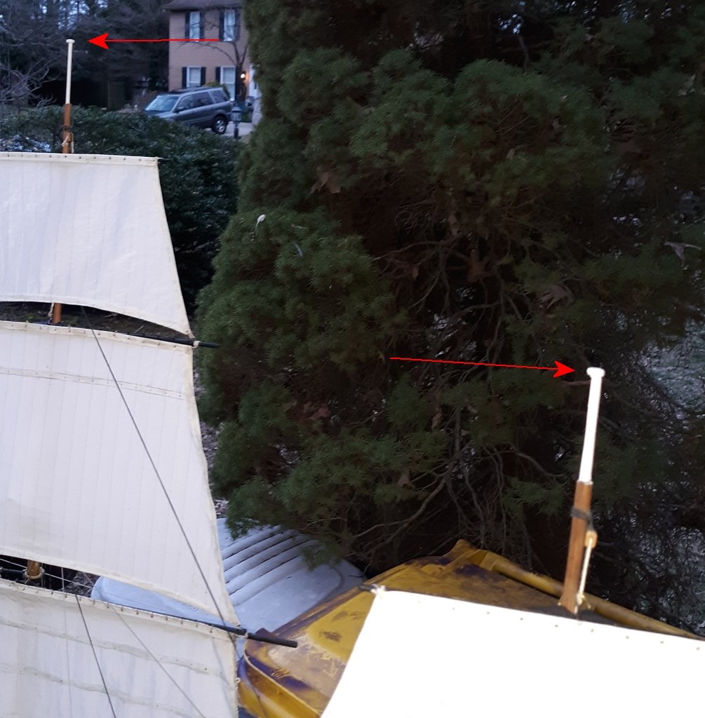
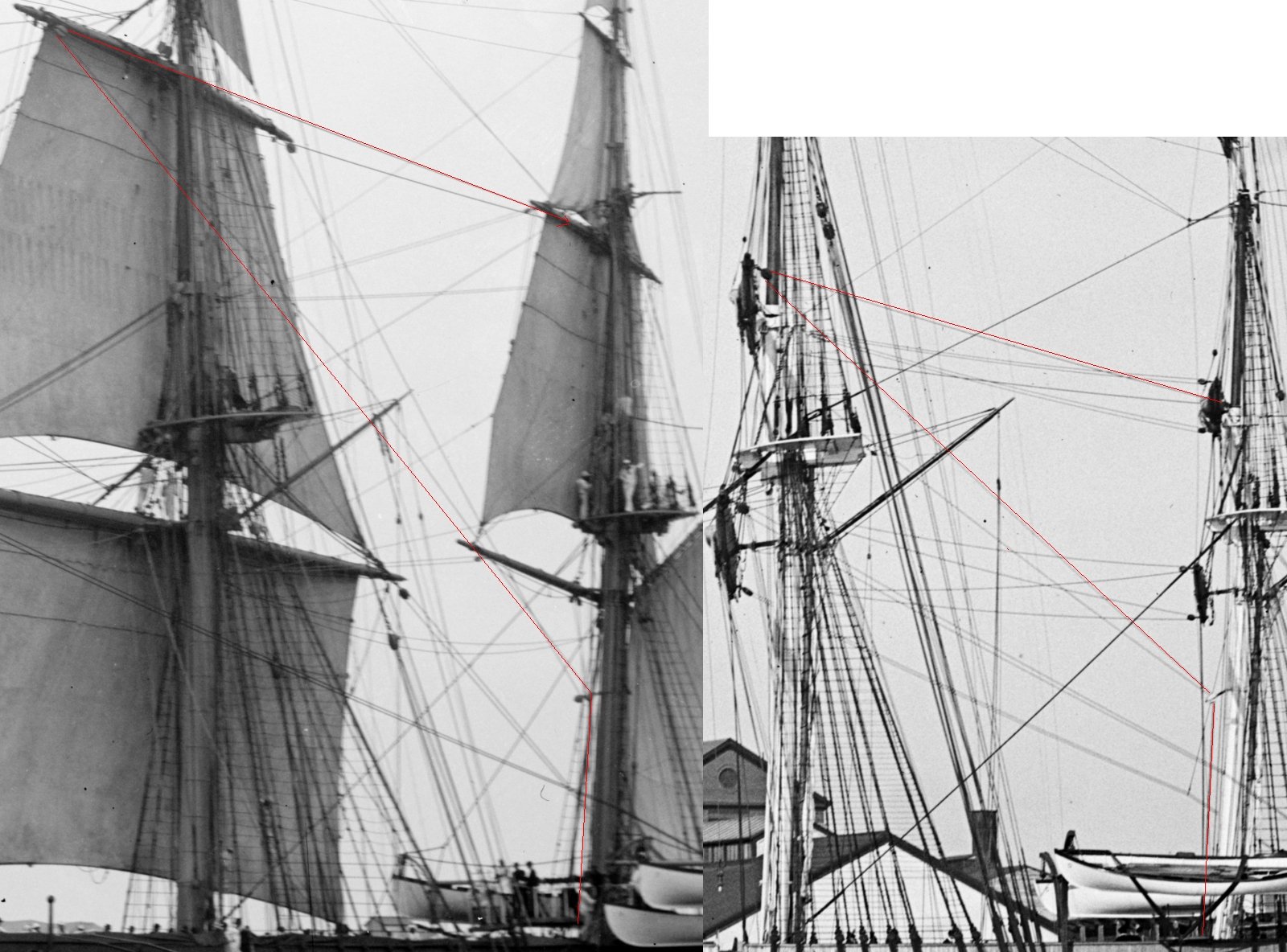
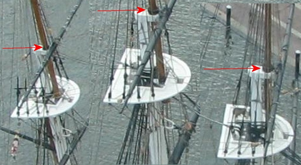
I'm taking to model to the Chesapeake Bay Maritime Museum's Model Boat Expo next month (May 19) where I plan to sail the model in the Miles River instead of the too shallow pool they set up. I want to use the other winch this time, and separately control the main and mizzen as they should be. To refresh my memory. I went to look at images of the ship to see where exactly these braces anchored. I thought the main tops'l brace anchored to the mizzen topmast stay, and it looked like it in images of the ship under sail, but in photos of the ship without sail, it appeared to anchor to the mast right at the mizzen tops'l yard. That was weird, so I went looking at some more pictures (I save every one I find) and it look like to was anchored right to the mizzen tops'l yard, maybe where the halyard attached? but it also looks like there's something on top of the parrell and there's something attached there that I don't see on the other top'sl yards. Maybe a ring that rides on top of the parrell? (BTW: The tops seem to angle forward because during the 1888 refit her masts were re-stepped to reduce the rake. Quite a bit it seems) So, it turns out there is indeed a ring that slides up and down the mast, and as seen here, doesn't always slide down completely. The left image in 1892, the right image in 1888. I don't know what it's made of. A hinged iron ring that a pin or bolt holds closed so it can be removed, or maybe a leather covered rope grommet which would explain those chains as giving it weight to make slide down the mast. Looking at photos of other ship's contemporary to Constellation, it does appear that other sloops were rigged this way; Savannah, Macedonian, St Marys, Saratoga, and Portsmouth that I've been able to discern from photos. Interesting is how they routed the braces when Saratoga were fitted with split tops'ls. I presume Portsmouth was likely done in the same manner. While I haven't confirmed this ring thing anywhere but on Constellation, I did notice that the main tops'l brace is routed to blocks partway down the mizzen mast on every American warship of this period (1850+) where I could see it, including frigates. In the painting of Constellation at anchor in Naples that I'm basing my model on, you can't see how the main tops'l yard is braced, but in the painting of her under sail by the same artist in 1862, those braces are visible, and deSimone does show those blocks on the mizzen mast. It is interesting that every time I get to some other point in the model's progress, I learn something new about how they did things in the Navy of that time. I'd never seen, rather, I'd never noticed that ring thing or anything like it before. How does all this affect my model? Not much really. I wondered if it would affect the geometry on my bracing system, but the tops'ls on the model will rarely be lowered so my operation is only concerned with it being in the set position.


- 553 replies
-
- 2
-
-
- sloop of war
- constellation
- (and 3 more)
-
American sailing warships with no plans or records
JerryTodd replied to CharlieZardoz's topic in Nautical/Naval History
No relation, Humphreys designed Macedonian specifically to replace the captured British frigate. She was a "modern" frigate in the older ship's dimensions.- 401 replies
-
- 2
-
-
- John Adams
- Alliance
- (and 3 more)
-
American sailing warships with no plans or records
JerryTodd replied to CharlieZardoz's topic in Nautical/Naval History
The new ship was deliberately built to about the same dimensions because Macedonian was still an important trophy and Decatur was still a hero.- 401 replies
-
- 2
-
-
- John Adams
- Alliance
- (and 3 more)