HOLIDAY DONATION DRIVE - SUPPORT MSW - DO YOUR PART TO KEEP THIS GREAT FORUM GOING! (Only 72 donations so far out of 49,000 members - Can we at least get 100? C'mon guys!)
×

JerryTodd
-
Posts
875 -
Joined
-
Last visited
Content Type
Profiles
Forums
Gallery
Events
Everything posted by JerryTodd
-

Rigging Instructions 1/96 Revell Constitution
JerryTodd replied to kruginmi's topic in Masting, rigging and sails
I've had 2 Constitutions and 2 United States kits since 1971 and have never seen the more "verbose" version of the rigging instructions. They must be newer versions. -
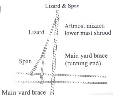
That would be a lizard such as the attached.
-
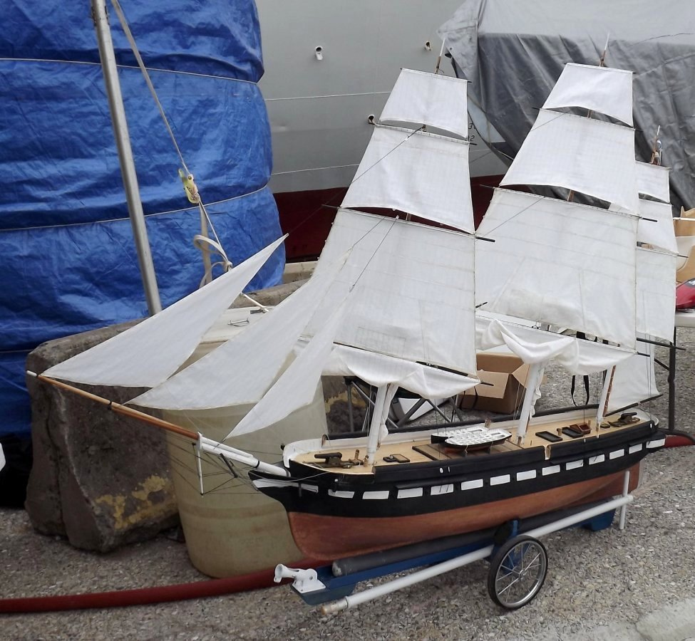
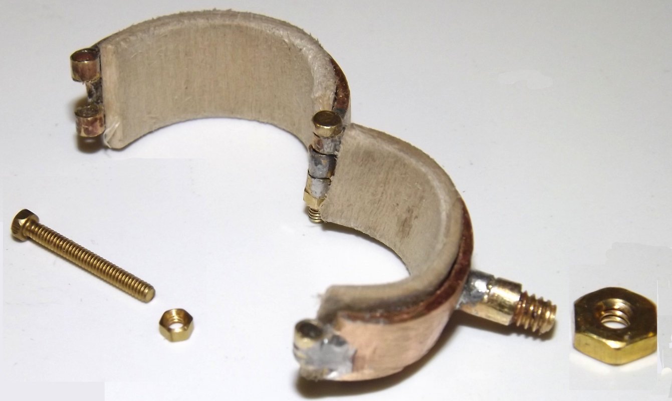
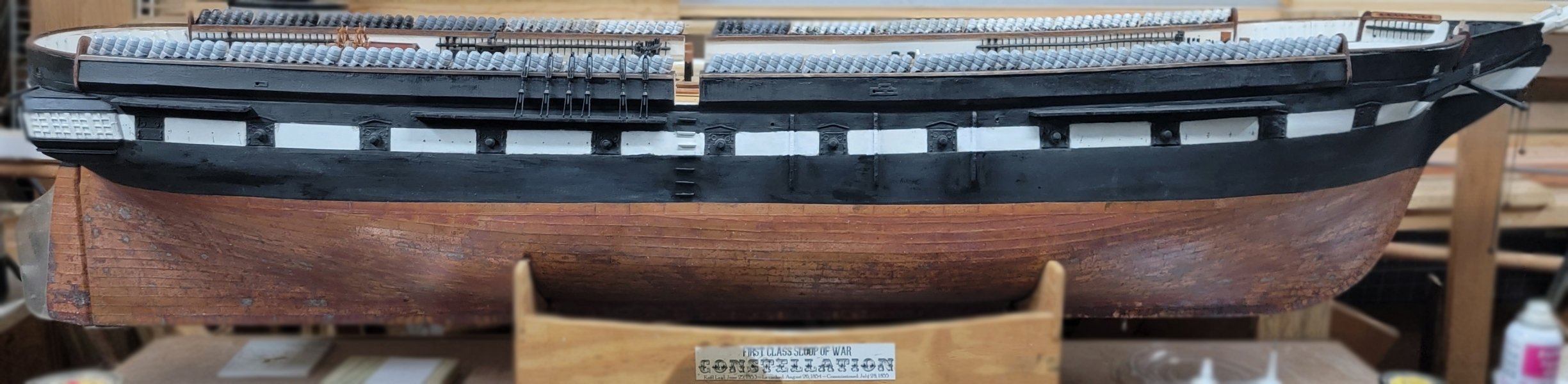
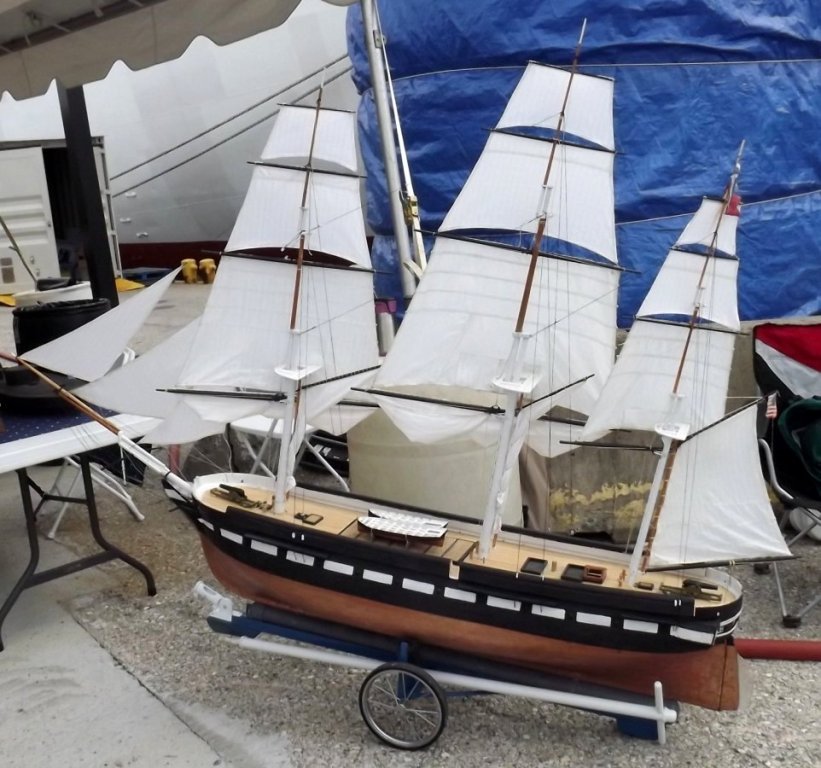
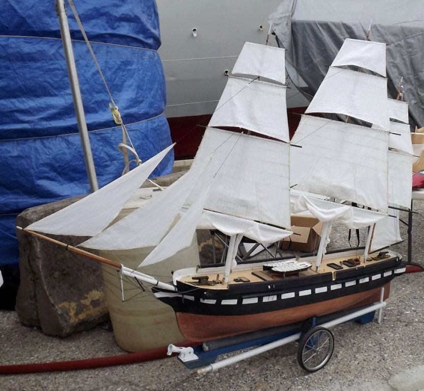
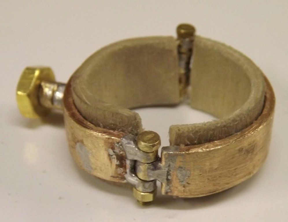
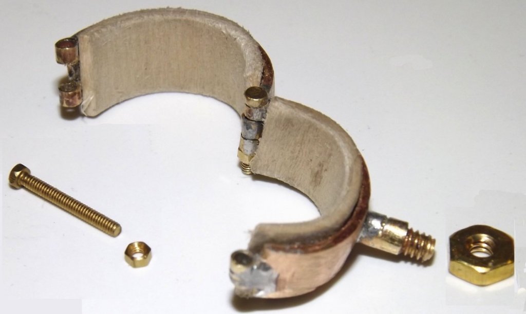
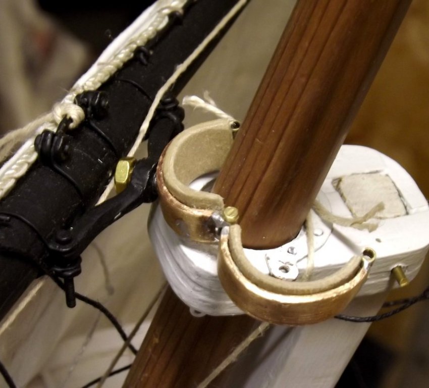
Sunday (5/21) past was the Baltimore Port Expo for National Maritime Day. I couldn't get the model ready to sail in time, and the pool was to shallow to allow it anyway, so she sat on her cart on display. She did wear all 17 sails and a lot of folks asked a lot of interesting and intelligent questions about her. I took another shot at the parrel I gave up on back in December and I think I got it this time. I'll get no offers to make jewelry or clocks, but I have a parrel. It's a 1/4 wide strip of 1/16" thick copper bent into a two-part ring. 1/16" i.d. brass tubing was soldiered the the ends to make hinges. The post for the yard's yoke is a brass #4 screw threaded and soldier to the copper band. A section of brass tubing was threaded onto it to cover the threads where the yoke will ride, and prevent the retaining nut from being over-tightened. It's lined with 3/8" tall, 1/16" thick bass, CAed inside the parrel so it doesn't mar the mast. I'll grind down that hex-nut smaller at some point. Just two more to go.

- 553 replies
-
- 7
-

-
- sloop of war
- constellation
- (and 3 more)
-
Copper tape wants a smooth surface, the smoother the better.
- 742 replies
-
- 5
-
-
- constitution
- frigate
- (and 1 more)
-
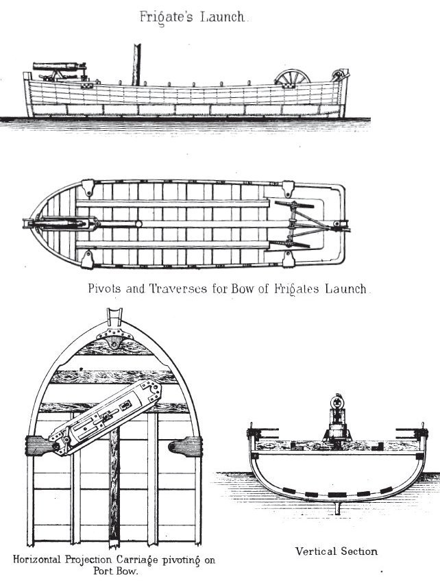
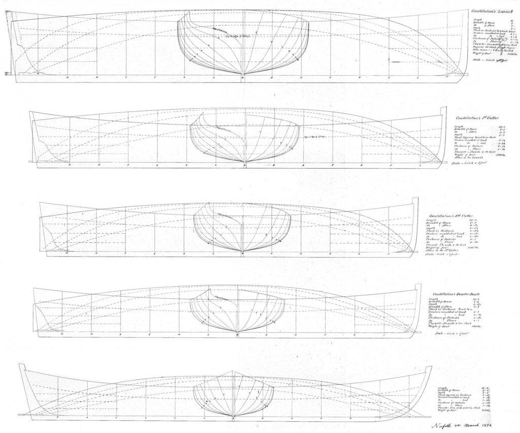
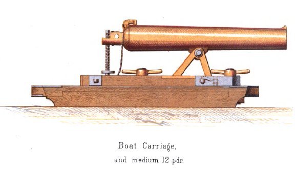
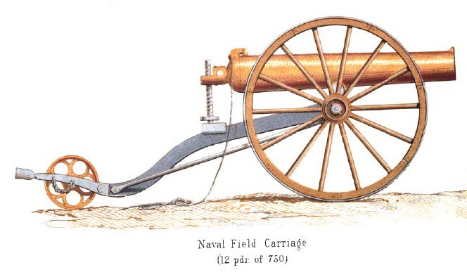
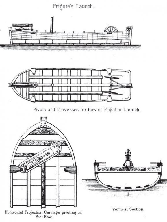
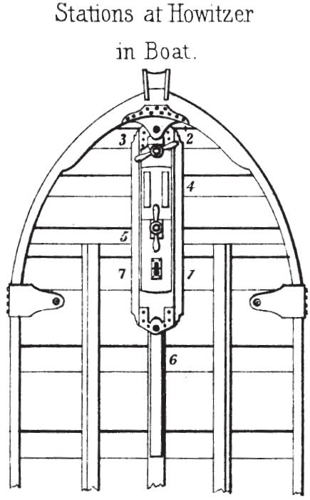
These are 1853-54 vintage; launch, cutters, quarter-boats, and stern boat for Constellation
-
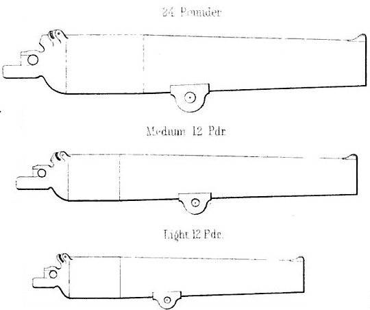
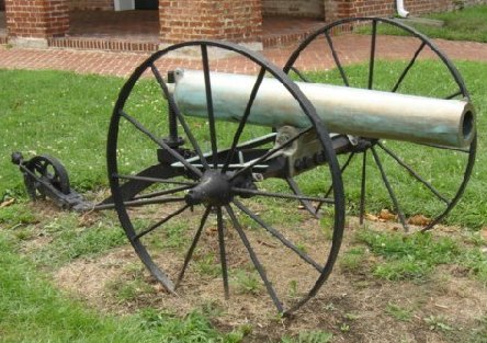
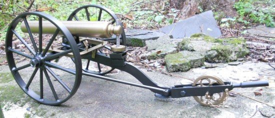
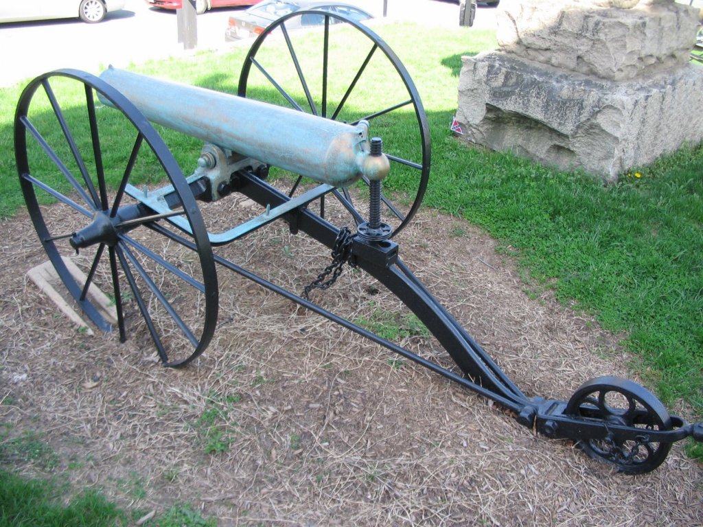
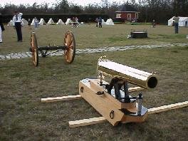
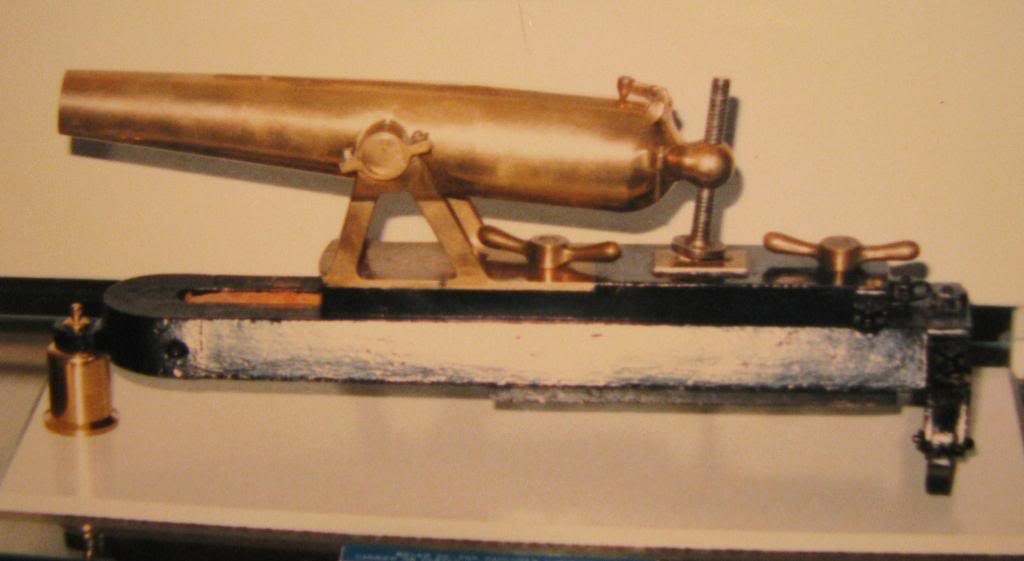
Did someone say boat howitzer? I needed to research this a bit for Constellation's launch
-
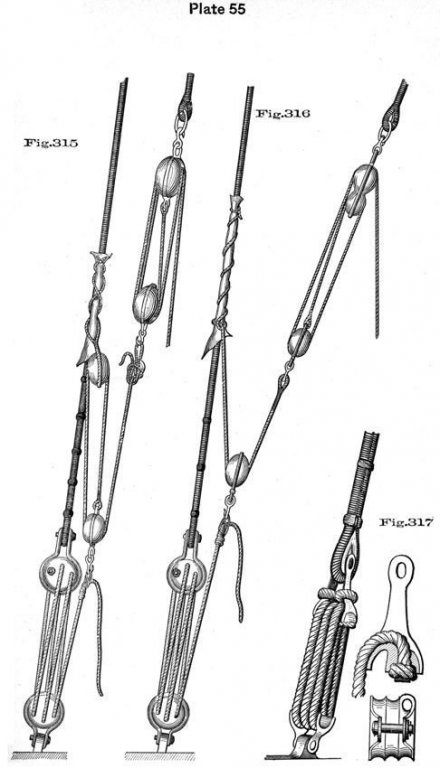
Lanyards and other "adjustment points" of that nature would definitely not be tarred with the coating Luce describes, mainly because it would prevent seeing any deterioration or damage on lines that wear most on the inside - like in the holes of the dead-eyes. Pine tar protects the line, mainly from molds, and keeps it supple, while allowing any wear to be visible and dealt with before it becomes critical - but it would be tarred beyond what it received in it's manufacture, making it much darker than the rest of the running rigging.
- 3,618 replies
-
- 7
-
-
- young america
- clipper
- (and 1 more)
-
The set-up for "adjusting" lanyards is perfectly capable of overcoming whatever "tar" they might have put on them. The odds are Stockholm Tar was used, but something was used, no passage making ship is going wandering about with bare lanyards. Yes, the system shown is from a Navy manual where there's enough crew to send the mast through the bottom of the ship, but the system's the same outside the Navy as well.
- 3,618 replies
-
- 9
-
-
- young america
- clipper
- (and 1 more)
-
Or staple on some bed-sheet from the thrift shop.
- 3,618 replies
-
- 4
-
-
- young america
- clipper
- (and 1 more)
-
I think you're displaced, not misplaced, we know where you are
-
Did all topsail schooners have ratlines on both masts?
JerryTodd replied to Cathead's topic in Masting, rigging and sails
There would be at least two lower stays on each mast, probably three on the foremast, and two stays with deadeyes or bullseyes on the cross-trees, for each topmast. The foremast would have backstays for the topmast where the tops'l peaks, and the t'gallant if there is provision for one, both on block-and-tackle, "running back-stays." The main tops'l would have at least one running back stay where the main-tops'l's jack yard peaks. The fore would have rats at least as far as can reach the tops'l yard as would the main if there's a square set on it, otherwise, the main probably didn't have any at all, or only on the lower shrouds. The main on sharp-raked craft would also have two running fore-stays from the mast-head to either side of the base of the fore-mast, and did not have a stay running from mast-head to mast head - it would foul the fores'l gaff peak. This is pretty standard for Baltimore clippers, pilot boats, revenue schooners, coastal schooners, etc. -
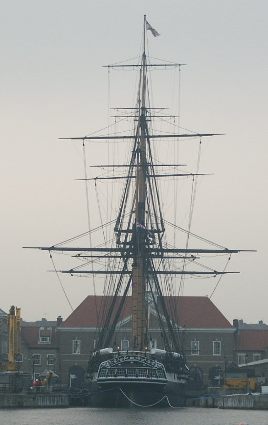
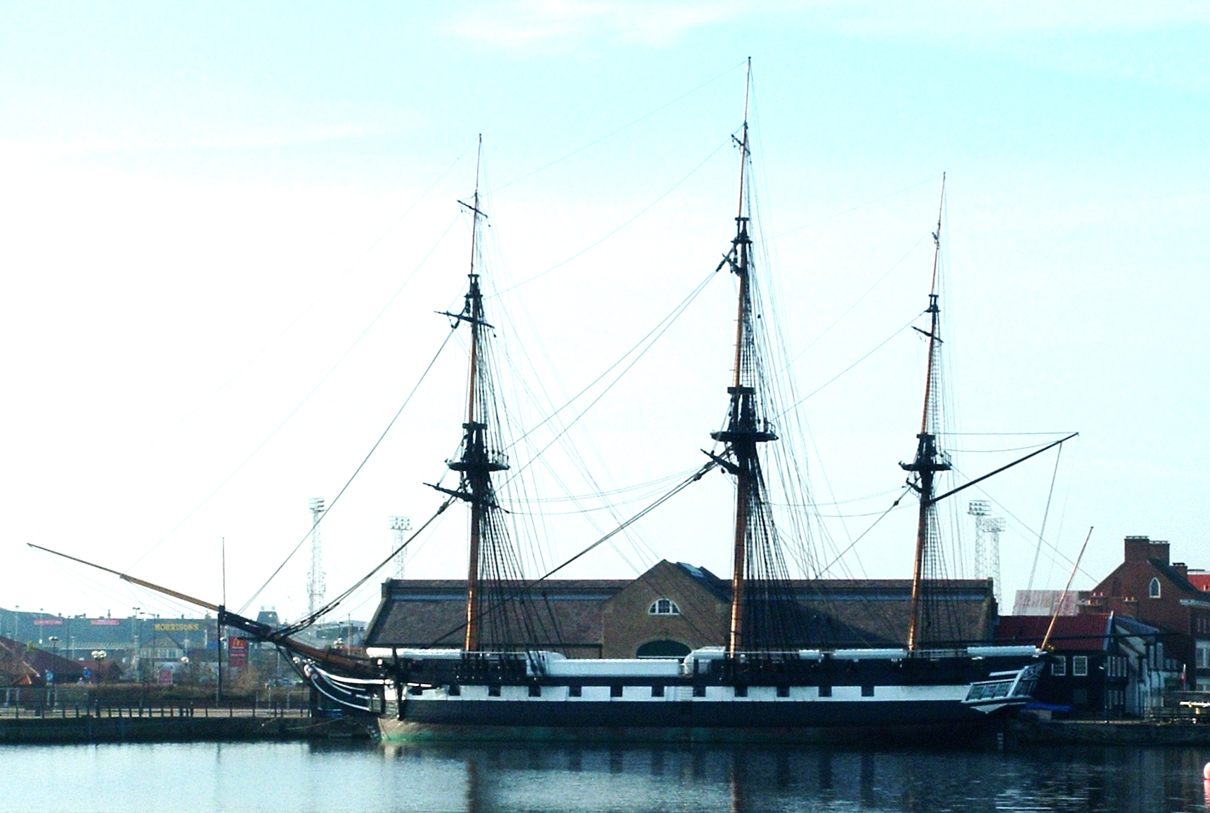
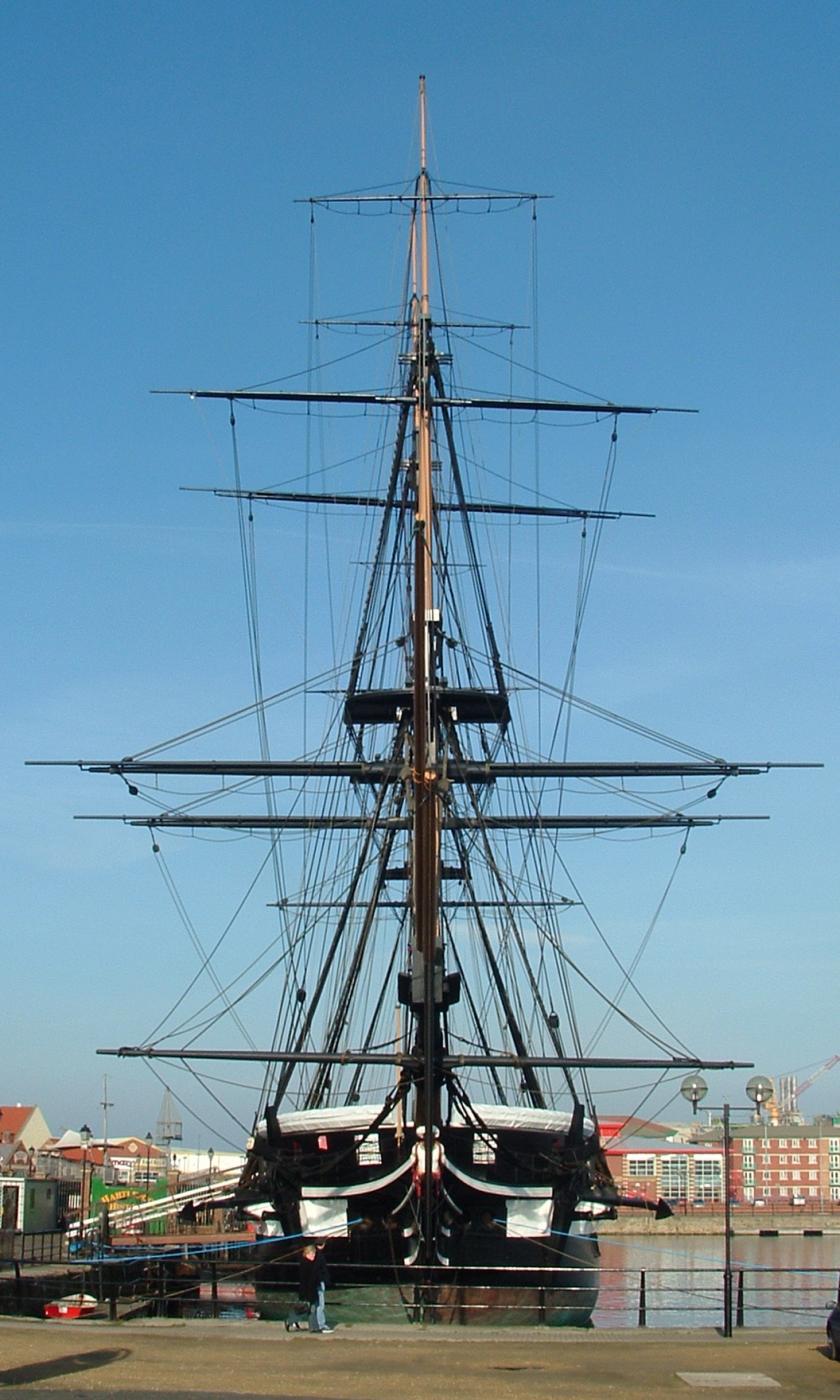
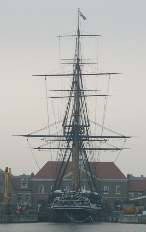
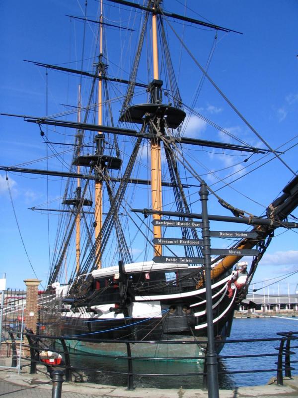
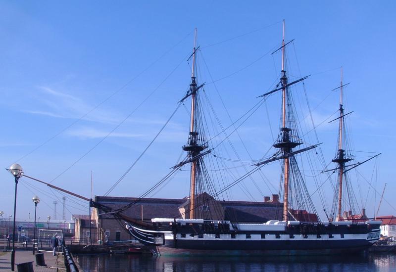
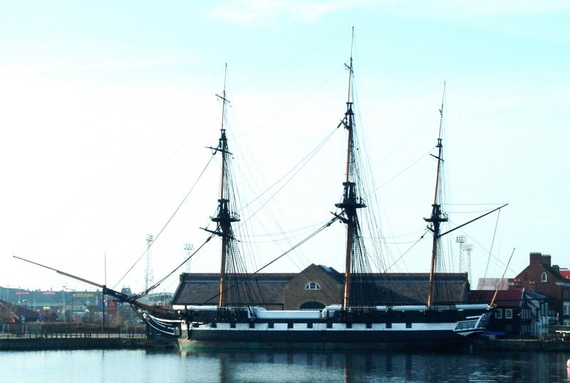
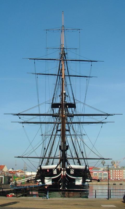
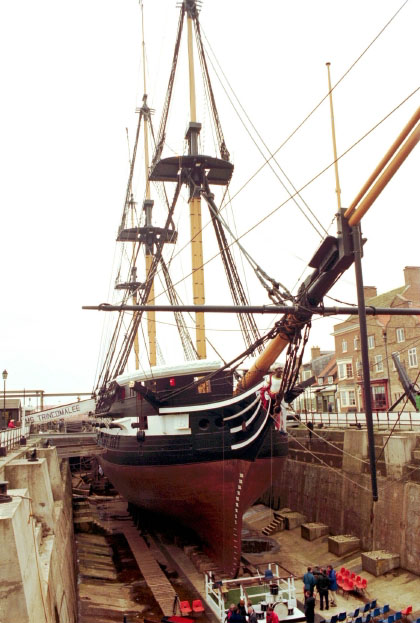
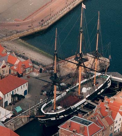
Some pics I found online over the years showing Trin out of her dock, in drydock, and other a-typical angles. I never did get why they set her up with the yards in the set positions.
- 13 replies
-
- 11
-
-
HMS Shannon, who took the Chesapeake, was a Leda class boat, and Unicorn, which also still exists, is a contemporary of Trincomalee and also a Leda. It's pretty lame considering some of the garbage that's offered as kits that there's no kit for these three notable vessels of a very notable class.
-
I'm a long way from needing jolly tars as yet; my need is for 1850's US sailors, Marines, and officers.
-
Water World and Heaven's Gate were epic movies, epic failures that is. There's a few kits that fit that version of "epic."
-
How Realistic Can One Make Sails?
JerryTodd replied to Julie Mo's topic in Masting, rigging and sails
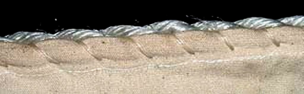
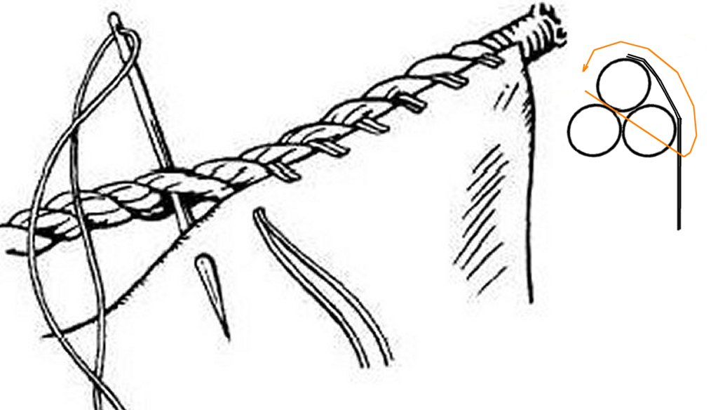
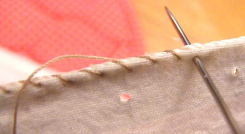
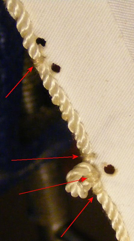
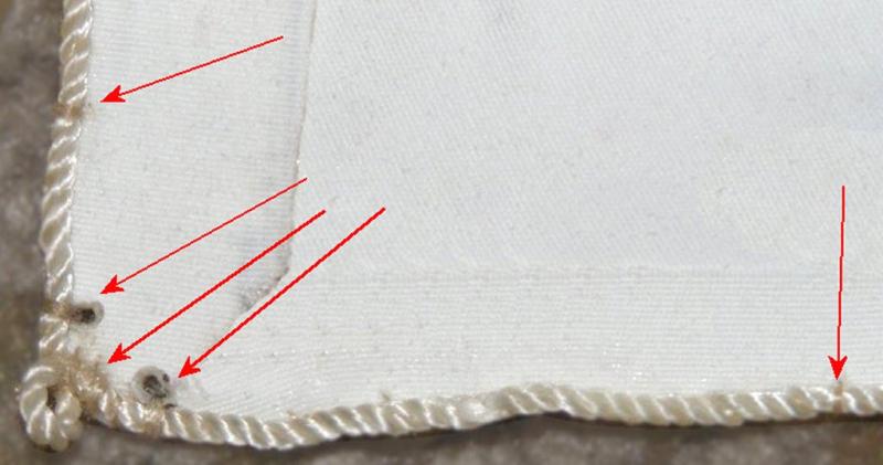
Bolt-ropes are sewn on in a paticular way. They do not attach to the edge of the cloth, but actually lie ON the cloth. On square sails the lie on the forward face of the sail so they are less apt to rub on shrouds, etc behind the sail. The stitching that holds them to the sail comes out of the sail, goes over the edge and into the bolt-rope, through the sail, and goes around again and through the next strand over. In reality the thread goes between strands and through the third, then into the sail. Going through one strand isn't critical on a model. The stitches advance along the sail with the lay of the bolt-rope so it buries itself in the lay of the line. I skip 3 or 4 rope strands, where-as the real thing is stitched in every strand of the bolt-rope. That's totally up to you. The real thread is waxed flax, heavy and doubled. On a model, one strand of light thread should be scale enough. Pull it snug in the direction you're sewing towards, not back where you've already sewn or the sail will draw up and kink. The sail will pucker a little into the lay of the rope - that's fine and as it should be, it wraps the sail around the bolt-rope. Every so often, a few turns are made, a whipping, typically every yard or so, on either side of grommets, eyes, and the like. These serve as pull-stops. If the stitching should break somewhere, being a whip-stitch it'll easily pull out, the whippings try to keep it from pulling out too far. This obviously isn't critical on a static model, but it can be seen if you look at real sails and besides adding a touch of realism, is a good place to start a new thread because the whole thing doesn't have to be done with one length of thread. I make cringles and eyes for my RC model's sails by taking a turn around a rod of the right diameter, like toothpicks, and whip it at the overlap. The real things were usually spliced in. That can usually be represented by just whipping a join of two ends of the bolt-rope with enough overlap for the eye and whipped at either end of the eye. In the pics, note how the stitching disappears into the lay of the bolt rope on the front of the sail. You need to hold out the sail and the bolt-rope as you sew it, don't stretch them, just keep some tension on both. My sails tend to be a much larger scale (1:36) than most models here, but with some good magnification, it's not difficult to do. I find it easier to insert the needle between strands on the front side, through the third (or not, it's your call), into the sail, snug it up, move 3 or 4 strands over, and do it again. I reinforce my bolt-ropes with fabric glue as they are working sails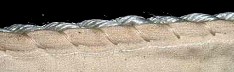


- 100 replies
-
- 10
-
-
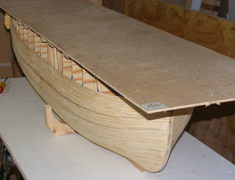
I don't think I have $1k into a 8 foot long RC sailing ship, including radio gear. It may be pushing $400.
-
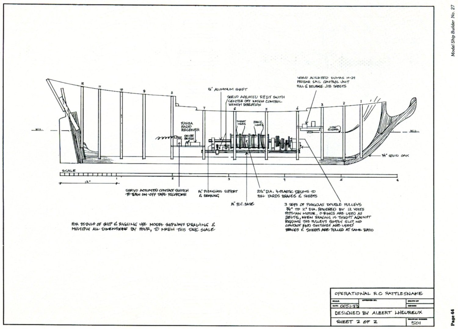
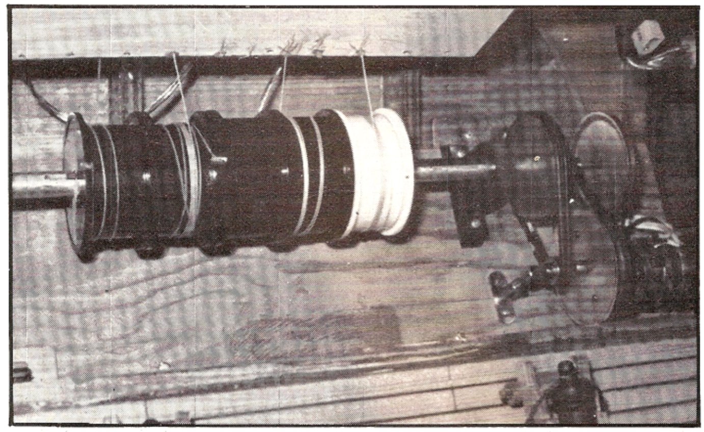
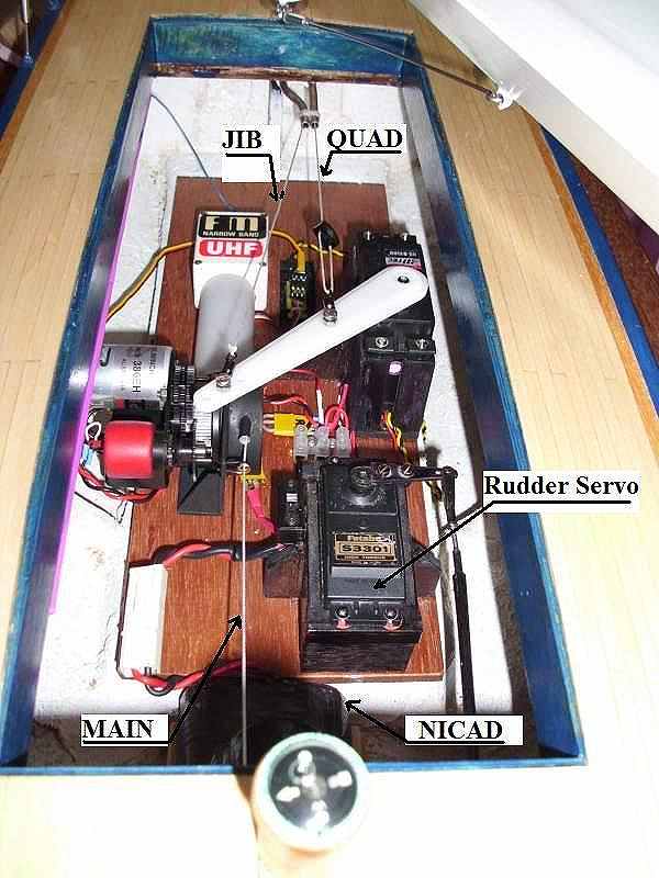
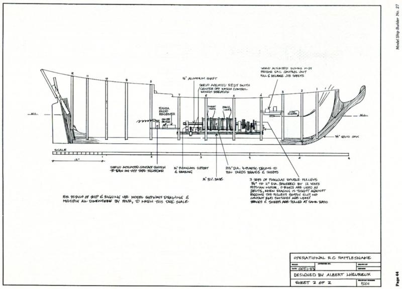
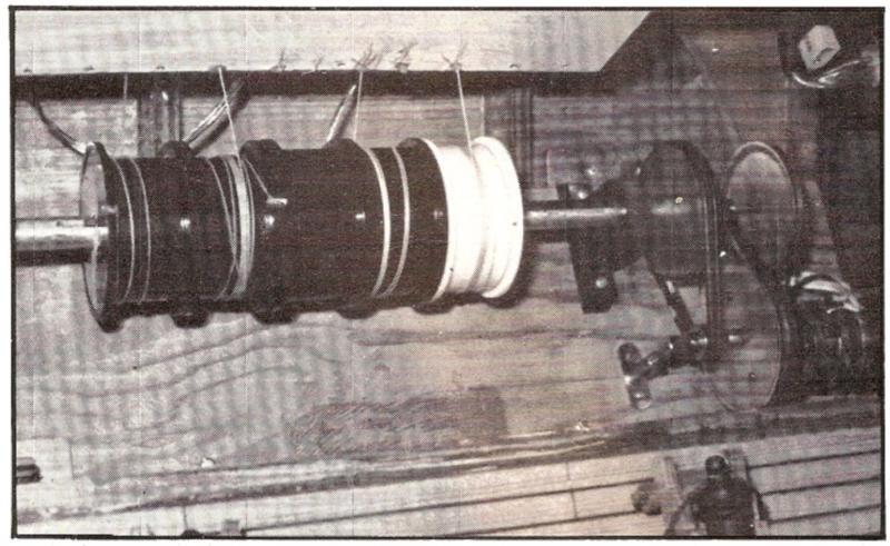
So it IS a boat you've been building! Some folks put a cover over the drum of the winch servo. It has to fit close to keep the line from getting between the flange and the cover, but the idea is to trap the coils of the sheet on the drum when there isn't tension. While to my eye it's looks sketchy; like if you pay out the sheet in no air, and the coils get inside each other on the drum; but the folks that use this seem happy with it; like John Dowd on his Bluenose and J-class Endeavor and Antony Bell on his Jolie Brise. Here's the works in Dowd's J-Class, note the main sheet winch on the left; My sail arm servo runs the "3-arm-sheeter" for the heads'ls, and it also sheets the driver/spanker (there used to be a difference) on the servo's arm directly. It sheets out the spanker with the servo centered, and sheets in when moved left OR right. With a servo-stretcher giving it 180° of travel, that gets me plenty of sheet. The spanker sheet anchors in the waterway, runs through a block on the boom, then to a fairlead in the opposite waterway, and on to the servo - so it is "doubled." My issue with the whole thing is the servo moves too fast. I'm sure there's some expensive item available that will deal with that, but I don't have one. Speaking of tension on drums, you may consider mounting your brace winches on their sides so the drum is vertical. Slack is much less of an issue this way, and it may help you out with space limitations and access. This pic shows two winch servos with a couple of Bizarroland drums to illustrate the idea, I hope. The braces would run athwartship from the drums, but you can turn this anyway you like I'd think. This idea is based on the old Rattlesnake that inspired me in the first place. L'Heureaux used a motor and slipping belts that I doubt gave him very good fine control, but that's not an issue with winch servos. The braces don't develop so much slack for this to be a problem if the flanges are deep enough, the spanker sheet can develop much more slack and could be a problem, even with the winch on it's side..

-
Most boats had a swell for the shrouds and stays like you'd see on a t'gallant mast for instance, but some had cleats or wedges instead. The shrouds tend to be looped around and clamped with a couple of wire clamps, but further back they were seized with wire. One newer boat I saw had a sort of spider band on the mast and the shrouds had thimbled eyes shackled to it.
-
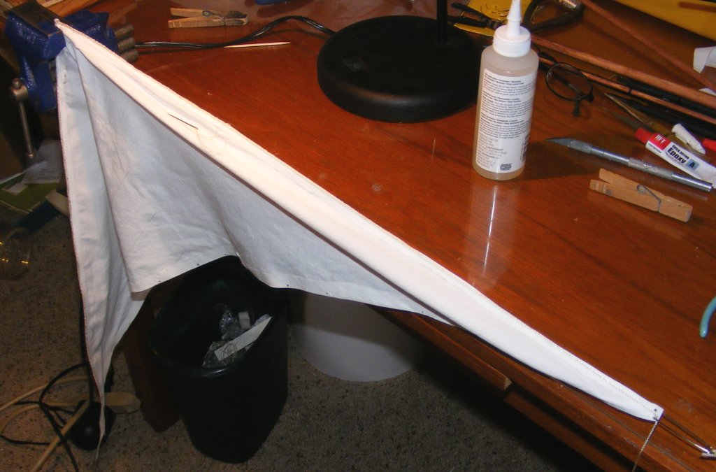
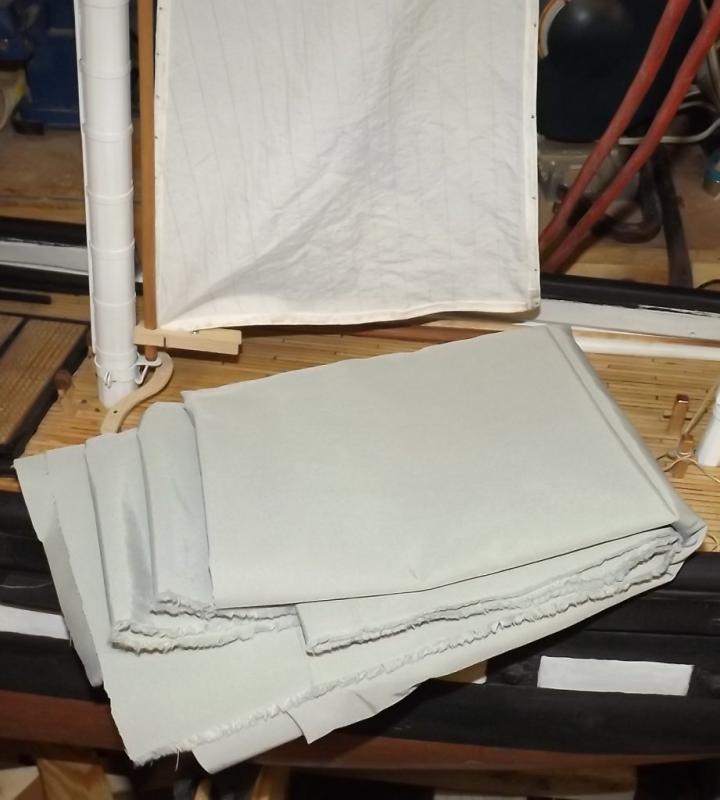
Got 2 yards of gray Supplex from a different supplier than usual. It was much cheaper than their normal price; a remnant maybe? It seemed a little dark, but not so bad in the photo, for the sails of a British frigate.
- 97 replies
-
- 3
-
-
- macedonian
- frigate
- (and 2 more)
-
I wager everyone that's built an extended frame model has had this little joke creep into their head.
-
Don't let these pudgy phalanges hear you, or I'll never get them to do what I want.
- 553 replies
-
- 2
-
-
- sloop of war
- constellation
- (and 3 more)