AON
-
Posts
2,772 -
Joined
-
Last visited
Content Type
Profiles
Forums
Gallery
Events
Everything posted by AON
-
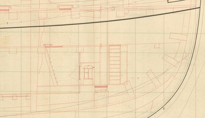
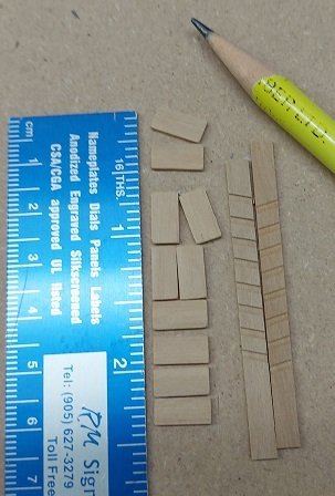
 The plans show two stairs at the bow. Both enclosed on all sides with a door on one likely so no one falls down the hole. So I made a set of ladders per the above drawings. At 24" wide they are quite narrow. They have been installed but I want to get some flush flooring and grating installed before the reveal. As I did not install the platform below they hang midair, but no one is likely to notice that.
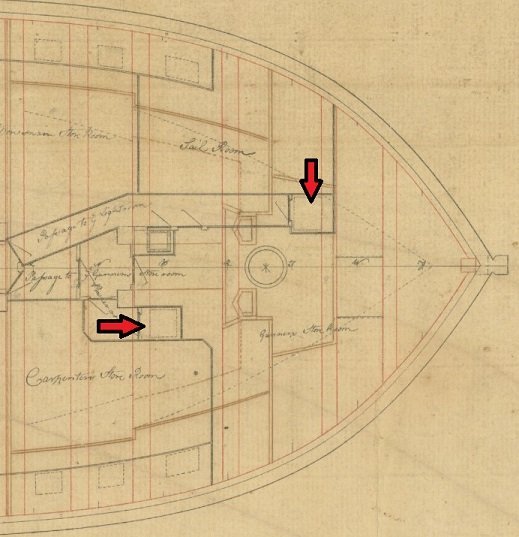

-
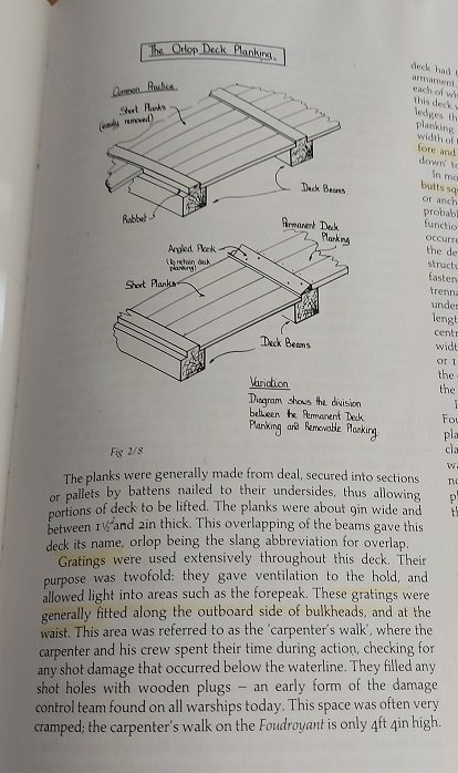
There is nothing I hate more then searching forever for information. So to alleviate others from that predicament here is the info from Goodwin's "Sailing Man of War" on the Orlop deck construction with grating fitting along the outboard sides of the bulkhead and the planking being flush and removable. First up is Page 59 Second Pg 64 showing hMS Victory. Funny thing is that I watched the walking tour videos of HMS Victory on YouTube and they do not agree with continuous grating along the sides. I can only suppose this changed over time and refits. The grating battens run fore and aft so there must be a support under the grating ledgers on the sides as depicted in the NRG Capstan Kit. In this case a ledge block on the carling beam (or the carling beam is notched?) and the vertical lodging knee on the outboard side (likely notched). Update: on closer inspection of the above it seems the carling is notched out to create a supporting ledge.
-
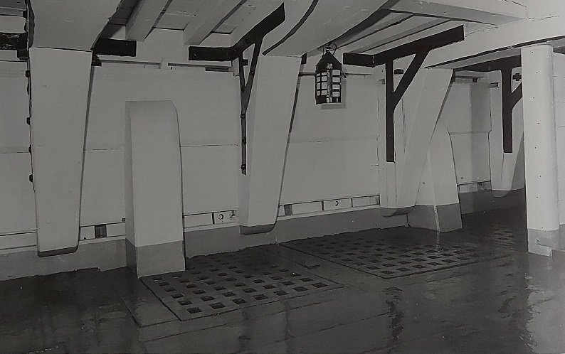
Possibly found one answer to one of my questions in post 1646 above. In the book Sailing Man Of War by Goodwin pg. 58/59 for The Orlop Deck. Gratings were generally fitted along the outboard side of the bulkheads and at the waist. They also state much of the flooring was removable So it may have been grating set into notches in the beams? Wait... that's another question. I'll keep looking Update... turned a few pages and pg 64 shows a photo of the orlop deck of the Victory... grating inset into the beams to be flush at the top.
-
Masting and rigging the Clipper Ship and Ocean Carrier by Harold A. Underhill, pg72 fig. Plate 15, at the top of the Royal Mast shows a sheave for the Royal Tye at the top just under the truck and head (or pole). at the top of the Topgallant Mast is a sheave for the Topgallant Tye. At the top of the Topmast under the trestle trees and cross trees is a sheave for the Upper Topsail Tye.
-
After seeing Druxey's image above I've decided, as a start, I will cut the ledge notches in situ. I've been cut the carling notches and beams as a bevel. It seems I've been cutting them too deep. That might be what my problem is. If I cut them shallower it would be easier? Druxey. Do you cut your's as a shallow pocket like the ledges? Also, if there are no lodging knees for the first three and last four locations what supports that end of the outboard ledge beams?
-
I like how you used the stiff cardboard to square things up. I tried notching on the model a short while ago. I had to open a notch a bit. I did not like it at all. It will take much more practice.
-
Okay Druxey... I try... one day.
-
I have the LVT Veritas chisel set and used them often but I can't imagine cutting these notches after gluing in place. I guess by the time I'm done may have a different opinion on the matter but not today. Also, I imagine needing to reach under the beam for holding lodging or hanging knees with a finger so not getting too far ahead would be of benefit providing room for my bear claw hands... but not having done any as yet I am likely wrong.
-
By miniature you mean extreme short (baby) chisels? And you've space to install the hanging and lodging knees? Are your fingers slimmer than mine? 🤣😂😇
-
If they were installed (glued in place) you notched them in situ? How did you manage that?
-
Contract reads that there are lodging knees and standard knees at each end fayed into the timbers except for the three foremost and four aft most beams and to sides of those beams for the 2nd futtock riders which are to have one lodging knee. Standard knees have their athwartships arm on the deck. So, memory being what it is, it is a good thing I double checked as I thought the first few had standard knees as opposed to hanging knees. No mention of any hanging knees for the orlop deck.
-
First the good news. I'm slowly learning how to easily make and notch the beams. Fitting is slow work. I use a crude sliding stick to measure the distance then cut the stock slightly over size and trim it to fit. I could measure off my framing plans... make a mental note to compare the measurements of the next beam I make... nope, better write that down. The bow has quite the curvature to it in both axis so that takes some concentration to shape the ends of the beam to rest or nest in place properly. I mark the depth of the crutch cut on two faces and was originally sawing multiple notches prior to chiselling out to the mark but I find just notching the extreme ends is enough. I saw just inside the pencil line. The sawing keeps the ends from chipping. Then I fit the crutch stock into the notch and open it a bit as required. So I've progressed to my first two beams having the crutches installed and all glued in place. The third beam, the one with the arms, is notched and ready to install and the fourth beam is marked and ready to notch. I mark the crutch notch locations off the plan I made for the gun deck. The contract stated the orlop deck beams are laid out like the gun deck above it. This is important to understand as I am about to mention the bad news. First I use my plumb to locate the centre of the beam. I have a string stretched from stem to stern on centre. My plumb is suspended from my height gauge beam and I inch it over, string beside string. The nib or point of the plumb is now just off one side of centre on the beam so I pencil mark the actual centre of the beam to one side of the plumb pointer. Then I place the beam, located with the centre mark, over my 1:64 scale paper plan for the gun deck and mark the notch locations. Easy enough. When I stopped late yesterday I left myself a note to work on the standard knees for the first few beams. Standard knees run vertically upwards above the beam. I have to check if they start actually on top of the beam or along side of the beam... make a mental note... nope, I'd best write that down too. This morning I awoke with a premonition I'd done something wrong. Double check and the plans show quite clearly that the orlop deck beams have none with arms like the gun deck above has. So the bad news is I made a beam with arms that is now scrap. The good news is I didn't glue it in place and I now know I can do it. Yeah me!
-
How to "unstick" this chuck from the mill spindle?
AON replied to rlb's topic in Modeling tools and Workshop Equipment
Excellent video! Answers all the questions. -
How to "unstick" this chuck from the mill spindle?
AON replied to rlb's topic in Modeling tools and Workshop Equipment
Some machines are designed that if you retract it completely it will self dislodge. That is how the spindle on most lathes work. -
How to "unstick" this chuck from the mill spindle?
AON replied to rlb's topic in Modeling tools and Workshop Equipment
If they are ball bearings they are not designed for a side force. As the spindle is vertical I'd suspect they are tapered roller bearings that will take side loading by design so light taps with a soft hammer/mallet should dislodge it. If not tapered roller bearings then the machine is a poor design mechanically speaking. If you use the long threaded bolt you might damage the threads. The rod should be a larger diameter so as not to engage or contact the threads at all. -
Welcome to the forum! Your comment about bending planks was interesting. Some steam, some soak, some "iron"... but it shouldn't be that difficult to do. I hope you have an opportunity to try again with the help of this group!
-
How to "unstick" this chuck from the mill spindle?
AON replied to rlb's topic in Modeling tools and Workshop Equipment
I do not have this machine but, having said that, there should always be an access hole on the far side to knock it out with a rod if/when it sticks. If you cannot see it, there must be a cover over it. It should be a tapered hole. Can you remove a cover? Put a towel or something below to catch it as it drops out. Good luck -
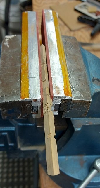
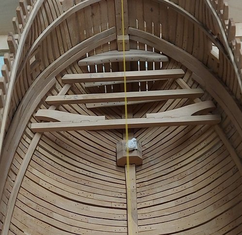
Thank you TBlack for that vote of confidence. Here is a photo of the beginning of the orlop beam fitting. It may be slow going for awhile - until I gain some confidence in myself. I hope what I learn here will help with the gundeck beams. The orlop beam layout is described as similar to the gundeck beams above it but smaller in size.
-
I corrected my post #1625. Started on the orlop deck yesterday As the rise or rounding is quite minimal and this deck is below two others, I will treat it as flat, to make it easier for me. I am happy I decided to do this deck as being a novice I am finding it quite the challenge. Two beams fitted near the bow and the first tries of each are in the scrap bin. (Actually they are put aside to resize for the ledges and such) I hope to get better at this soon. I'll post photos when there is something I'm proud of.
-
No sir. Your message was quite clear to everyone but me. You even had the correct emoji! There is only one whale appendage here... oh wait... you meant silly person. 🤣 That good sir would be me! Regarding the 22 orlop beams and the original contract. They are the only beams that do not mention a rounded or rise dimension per the contract page 7. [**correction: page 1 states it is rounded 2-1/2" which is a mere 1/32" at 1:64 scale] I suppose due to being below the waterline there is nowhere to run off to but down to the bilge. These beams range in size from 15-1/4" to 12" square. (0.238" to 0.188" or 6 mm to 4.8 mm) I've cut up stock at 0.235" square and will use that throughout the orlop deck to simplify something that will barely be seen.
-
Now that is quite funny! I'm sorry you had to explain it.
-
I don't visit this topic often enough. Allow me to add a late Welcome to the group from a fellow Ontari-ari-ari-oh-ian with roots well anchored in the rock.
-
Welcome to the group. Hope to see you building and posting about it soon.
-
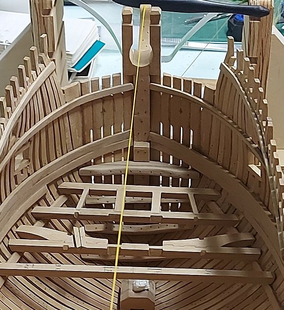
I actually did one other thing to personalize it. The hint of which is mentioned in my very first post. Possibly in 100 years someone will have a reason to get inside with a small camera and discover it.
-
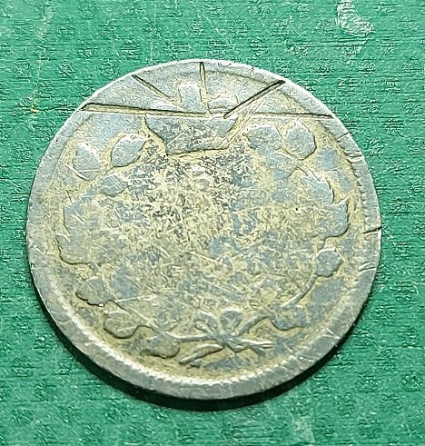
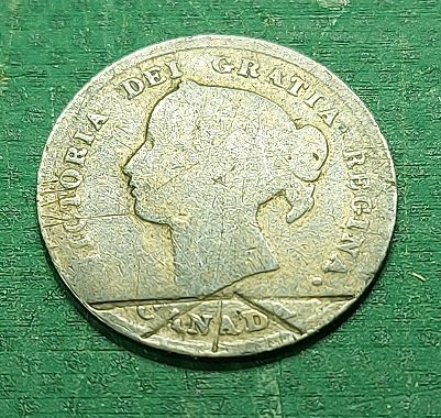
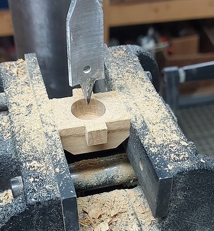
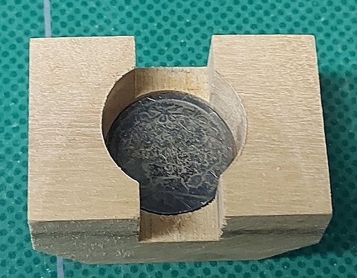
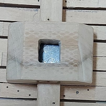
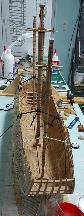
Made and installed the main and mizzen mast steps. I simplified them as they won't be seen. One thing was desperately needed to be added... a coin for good luck. I have an 1896 Queen Victoria 5 cent Canadian silver coin. About 15.35 mm diameter. It is quite battered up and worth about $12 max. on a good day. I drilled out the bottom of the main mast step with a 5/8 spade bit, inserted the coin face up, and installed it in place permanently. Am I ready to start the deck beams? I think so. Have to remove the masts first and put them back in storage.