


AON
-
Posts
2,880 -
Joined
-
Last visited
Content Type
Profiles
Forums
Gallery
Events
Everything posted by AON
-

Mariner's Astrolabe, full scale, AON
AON replied to AON's topic in CAD and 3D Modelling/Drafting Plans with Software
All the parts cleaned up.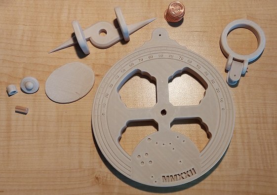
- 36 replies
-
- 6
-

-
- Navigation
- Instrument
- (and 1 more)
-
Mariner's Astrolabe, full scale, AON
AON replied to AON's topic in CAD and 3D Modelling/Drafting Plans with Software
Over the last two days I completed the clean up and dry fitting. Yesterday morning I did a test with the epoxy on two rafts to make sure it didn't dissolve the PLA/wood fibre material. Yesterday evening I glued the cover on the back and the hub or spigot back onto the face. The hub broke off in cleaning and fitting parts. As the hot printer nozzle lays and presses a layer of filament on top of a lower layer, the layer becomes a wee bit wider than one would hope for at mating surfaces, hole and hubs. So holes need to be opened up, flashes cleaned off, and hubs need similar treatment. I ended up with a slight interference fit between the pointer and hub, or so I thought, but turning the pointer might have twisted the hub a bit, weakening it. When I attempted to disassemble them the hub snapped clean off. I repaired this with a short piece of 1/4" wooden dowel and epoxy. I put a groove down the length of the dowel and filed a couple shallow notches in the hub matching hole so when the epoxy set the spigot hub to base assembly cannot spin. If I were making more of these there are a two things I'd change: Increase the fit tolerance for less cleanup and increase the embossed numbers to a bolder font. Below is the result, dry fitted, in stages.- 36 replies
-
- 6
-
-
- Navigation
- Instrument
- (and 1 more)
-
Mariner's Astrolabe, full scale, AON
AON replied to AON's topic in CAD and 3D Modelling/Drafting Plans with Software
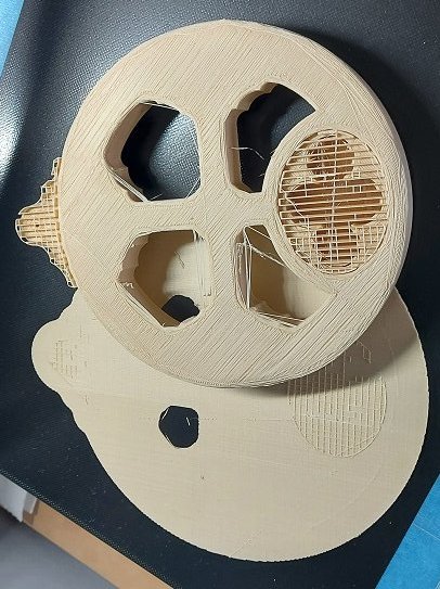
The print finished after 17 hours and 5 minutes So much for the 15hr 3min estimate. Here you see the finish front. Needs a bit of cleaning up. Dimensions are body 6" diameter x 5/8" thick and 7" tall over the crown Next is the back or rear that faced the raft and glass. As this was hidden it could not be "ironed" as the front or top face was. This will need a bit more sanding and cleaning. And that is why I print four layers instead of two. For those unfamiliar you can see the "supports" in the ballast coin cavity and on the crown. As these were steps up in the build process those layers needed supports provided under them or the machine would have been printing in mid air!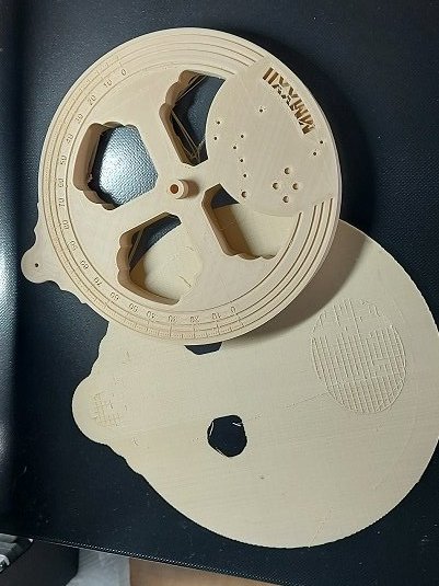
- 36 replies
-
- 10
-
-
- Navigation
- Instrument
- (and 1 more)
-
Mariner's Astrolabe, full scale, AON
AON replied to AON's topic in CAD and 3D Modelling/Drafting Plans with Software
more likely an early quadrant.- 36 replies
-
- 4
-
-

-
- Navigation
- Instrument
- (and 1 more)
-
Mariner's Astrolabe, full scale, AON
AON replied to AON's topic in CAD and 3D Modelling/Drafting Plans with Software
Now I am anxiously awaiting it to complete the top layers and hub or spigot for the pointer. Tomorrow I will clean it up with various sand papers, and check the fit of the pointer, lower swivel and ballast back cover plate.... and the coins. I will slip a note on top of the coins for the person that some day might open it up.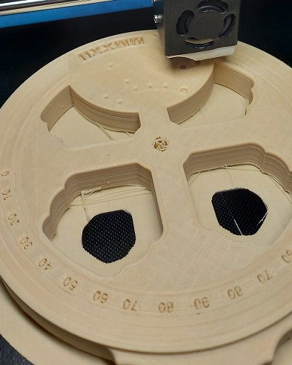
- 36 replies
-
- 8
-
-
- Navigation
- Instrument
- (and 1 more)
-
Mariner's Astrolabe, full scale, AON
AON replied to AON's topic in CAD and 3D Modelling/Drafting Plans with Software
My print settings are mostly default. I change the wall thickness to 4 layers, and 20% infill (Grid pattern). This means the inside is not hollow nor is it solid. Saves on material, cost and time. Print temperature is 210°C, bed temperature is 60°C. I always use a build raft and reduce the margin to 10mm outside the object. I use a raft because somehow that always sticks to the bed and the object always sticks to it. If I don't use a raft a successful print is a complete gamble. Here you can see the base printed, the raft is under it, on top of the glass bed. You can also see the 20% infill. At the top is a shamrock shaped outline. It is filled with a "support" that I will remove when cleaning up. The support is what the top face prints over to close this rear access pocket. This is where the coins will go.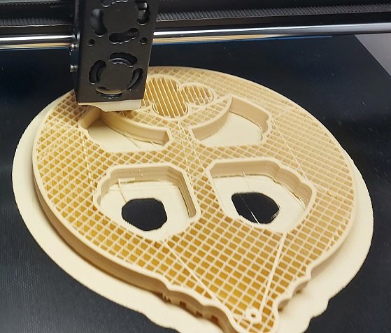
- 36 replies
-
- 7
-
-
- Navigation
- Instrument
- (and 1 more)
-
Mariner's Astrolabe, full scale, AON
AON replied to AON's topic in CAD and 3D Modelling/Drafting Plans with Software
My 3D printer is a JGAURORA A5 as seen below. If interested you can google it and see the specs for the unit. I have the option to connect it directly to my computer but I choose to use a Thumb Drive (USB Stick)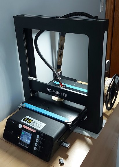
- 36 replies
-
- 6
-
-
- Navigation
- Instrument
- (and 1 more)
-
Mariner's Astrolabe, full scale, AON
AON replied to AON's topic in CAD and 3D Modelling/Drafting Plans with Software
I should mention the costs are for material only, not electricity nor design time. I also want to mention my adornments on the ballast face side. I added the year in Roman numerals (2022) and the dots are not braille. It is a star map of the Little Dipper with the north star and the Southern Cross and the three others used to find the south pole.- 36 replies
-
- 6
-
-
- Navigation
- Instrument
- (and 1 more)
-
Mariner's Astrolabe, full scale, AON
AON replied to AON's topic in CAD and 3D Modelling/Drafting Plans with Software
I use the free Ultimaker Cura version 4.13.1 to create my g-code to print. I will post pics of the printed parts tomorrow. I am using a PLA/wood filler filament. It can be easily sanded with regular wood sand paper. Here is the data I've collected so far. PART EST`D ACT. WT. LG. COST 1. body 15h 3m ???? 127g 42.47m $3.80 2. Pointer 2h 19m 2h 41m 20g 6.6m $0.59 3. Plug 19m 22m 2g 0.79m $0.07 4. Swivel 27m 34m 4g 1.23m $0.11 5. Ring 1h 27m 1h 43m 12g 4.11m $0.37 6. Cover 1h 15m 1h 18m 8g 2.71m $0.24 Total 173g 57.91m $5.18- 36 replies
-
- 4
-
-
- Navigation
- Instrument
- (and 1 more)
-
Mariner's Astrolabe, full scale, AON
AON replied to AON's topic in CAD and 3D Modelling/Drafting Plans with Software
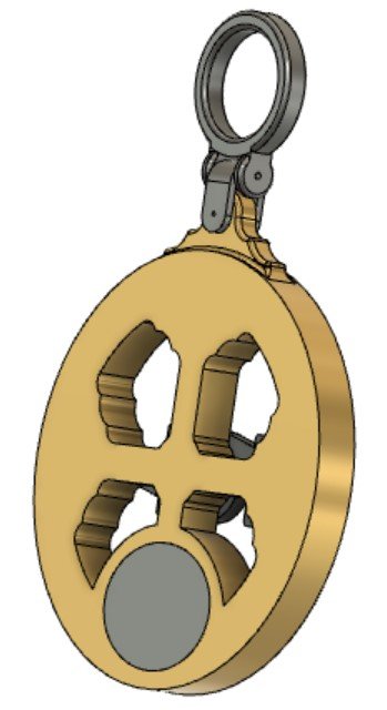
This is my 3D model (created in Fusion 360 - free hobbist version). Front and back view. There will be six printed parts and two copper wire pins. The body, pointer, plug (on the post over the pointer), lower swivel joint, upper swivel ring, and a back ballast cover. I need the ballast cover to cover the cavity I've created to place a number of coins to create ballast weight as the 3D printed version only weighs in at about about 173 grams. My weight will be a number of 1 cent Canadian coins... not in use, not accepted as currency anymore.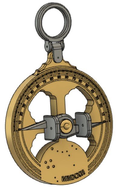
- 36 replies
-
- 4
-
-
- Navigation
- Instrument
- (and 1 more)
-
Mariner's Astrolabe, full scale, AON
AON replied to AON's topic in CAD and 3D Modelling/Drafting Plans with Software
This figure was the basis of my model. An astrolabe retrieved from a Spanish wreck.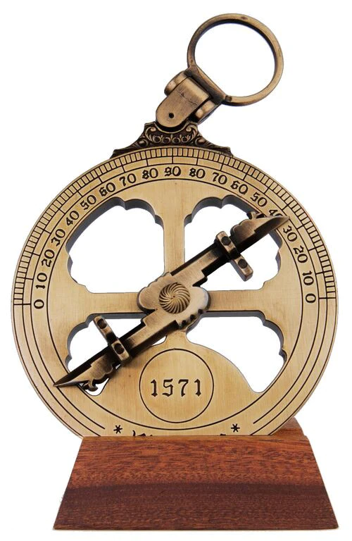
- 36 replies
-
- 4
-
-
- Navigation
- Instrument
- (and 1 more)
-
I seem to be getting more done on her outside on the patio then when down in the dungeon.
-
YES! That is my height gauge.
-
here are the stages
-
Just opened this log. Will start posting here once some items are organized. I was reading about maps and charts and once again they alluded to navigators using special instruments. After having researched how it was done with different instruments I decided to create a 3D model of a working mariners Astrolabe. At this moment I am printing the last part... well my printer's doing the work... I'm outside basking in the summer sun ☀️.
- 36 replies
-
- 3
-
-
- Navigation
- Instrument
- (and 1 more)
-
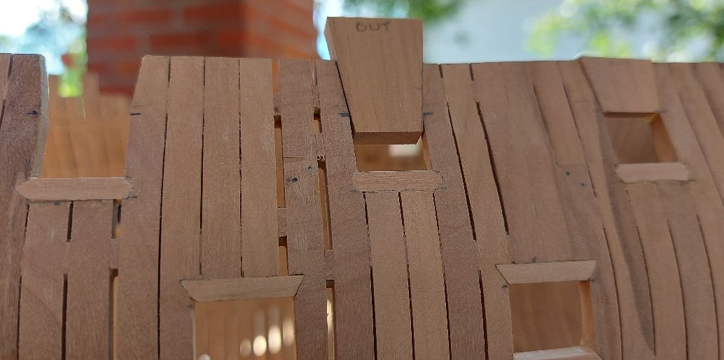
Gundeck done. Upperdeck started with the plugs in lieu of the upper cill at the eight (4 per side) midships gun ports. I will post a photo of that later today. I made my top timbers thicker then needed because they are quite thin at 5-1/4, 5-1/2, and 6" deep (about 3/32" at 1:64 scale). I was concerned I might damage them as they seemed fragile to me, so I now have some additional sanding to do. Presently I am into hour 6 of 15 to 3D print the last part of my working mariners astrolabe. I'll likely create a build log in the 3D section for it.
-
Wonderful use of the width jig and centering template.
-
Golden Hind by Rock_From_Korea - 1:48
AON replied to Rock_From_Korea's topic in - Build logs for subjects built 1501 - 1750
He states that he scratched it with a thin file. There is no mention of any other steps. If there were any I would certainly like to read about them! -
Golden Hind by Rock_From_Korea - 1:48
AON replied to Rock_From_Korea's topic in - Build logs for subjects built 1501 - 1750
I like how you did the window panes.... I think I may be copying that. -
On this day in 1815 Napoleon surrendered to Capt. Maitland on board the Bellerophon.
-
Nice job! Now for me to remember it all. I was concerned about the metal end of your clamp maring the plank when turned to tighten and was imagining various ways to avoid it ... and then you showed the simple soft wooden nose piece add on solution. Simple and effective... like everything you show us. Thank you.
-
Thanks. Sitting in the office waiting now. It was scary at first but, like everything else, after I managed the first one or two I felt better about it all.
-
Gun Deck upper cills done. One lower cill done... and I am quite happy with it. It is not sanded flush yet and will have to wait a few days as I'm off to the eye doctor for my 9 week visit.
