


AON
-
Posts
2,876 -
Joined
-
Last visited
Content Type
Profiles
Forums
Gallery
Events
Everything posted by AON
-
 Nothing done on my build the last couple weeks. Recovery from another needle in my eye, 47th wedding anniversary, 69th birthday. But I was back at her today. Dry fitted the timbers to the roundhouse transom beam. My timbers were made taller on purpose so they could be trimmed after fitted. Learnt quite a bit so it was all worth the effort and delaying the inevitable.... then tore it all off. The next time will be better.
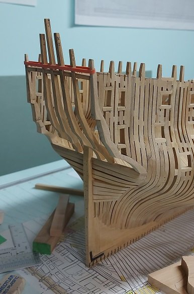
-
He does know his stuff (and then some)! 😇
-
That is the problem with good photos... they seem to highlight things the eye never focuses on! Having stated that, I think you did a wonderful job.
-
Good evening Bob, Been staring at your posting for a bit now. Don't know whether to pick like, sad or wow. I am so sorry for your loss. Four years must seem like yesterday. I wish you every success in finishing Cheryl's Niagara. Alan
-
Golden Hind by Rock_From_Korea - 1:48
AON replied to Rock_From_Korea's topic in - Build logs for subjects built 1501 - 1750
Possibly maintaining one common angle to the decreasing height right angle triangles might be pleasing to the eye. Presently the angles vary which might be what is distracting to the balance. Otherwise I think it looks amazing. Well done. As for COVID. It is climbing back here in Canada... it never went away, people just decided they had enough of it and any restrictions imposed. I understand that if we'd have only kept wearing masks the damn virus would have died out as it could not have been passed on. Masks kept Covid, Influenza (the flu), and the common cold at bay... and now cases are increasing and heads are buried deep in the sand. I have always been impressed by the care people in the far east display for their neighbours. Donning a mask when having the sniffles so as not to pass on any cold. Here it seems people are more concerned for their "assumed rights" then the health of their fellow man, and politicians are more concerned with our vote then our health. -
I always had to see the assembly being built, fitted together, in my minds eye before I could start a 2D drawing. I was surprised when I learnt not all people do this. We had a very talented wood carver in our office, he had won ribbons for his life like birds. I couldn't believe he could produce things so beautiful but could not envision a mechanical assembly to draw it! 3D does require a good deal of advanced planning that I still find challenging.
-
five counter timbers made and tapered. roundhouse transom beam marked off. all three transom beams removed now. eye needle tomorrow (ouch) morning so I'll be staying out of the dust for the rest of today and until after the weekend. when I get back at her I'll notch the roundhouse transom beam for the five counter timbers and assemble these. Then I'll mark and cut the other two transom beams and install them then I will build in all the other timbers and beams.
-
Gary You ask why? I ask why not? Living up to my motto I suppose: "only dead fish go with the flow!" The wing transom and deck transoms are two different radii per the plan. The horizontal distance from the foot of each counter timber (vertical beam) to the seat transom (the one below the quarter deck transom) are different from each other on the one (half) side of the ship so the lower arcs of each are different to accommodate the change. At least that is what I deduced from it all. If I sand them all together that difference wouldn't be met... or I am overthinking it all. I'll make templates to fit to my transoms, make my counter timbers, then taper them. Then remark my transoms to locate the tapered counters. Then I will remove my transoms to notch them to fit the tapered counters. In my mind it seems perfectly logical and simple but as this is my very first attempt it could be a nightmare or car crash! Stay tuned.
-
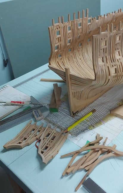
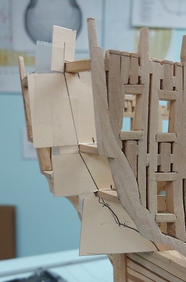
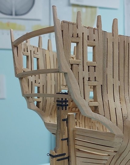
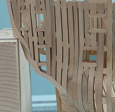
I made one cardboard piecemeal template for one set of timbers (photo below) Then I made the timber set, two sheets of wood stuck together with rubber cement so you cut once to get two matching sets. You apply the rubber cement to both sheets, let it dry then press them together to hold. After cutting, cleaning the cement residue with a crepe eraser, sanding and test fitting as best possible without notches, the foot of the cut timbers were bevelled at about a 5° angle (photo below). Interesting observation Druxey. You see something but it is not what you think. In reality the side counter timber tops are in the correct location. The timbers are supposed to be a straight line tilting outwards and down to what I will call the knuckle which rounds outwards (see posting #1447). In my clumsy, inattentive, and inexperienced effort of shaping these in situ the straight portion actually rounds inwards (see posting #1458). I realized this a few days ago when I had first attempted to layout the inner counter timbers and could not visualize what was wrong. The black strings made it pop for me. I was going to tear it all out and start over but decided to continue and gain more experience and will decide after I 'get her done' as they say. I imagine if torn out it will set me back a couple months. The second time is always quicker and normally better. I could possibly do a better job with the door cills too. On the other hand, everything is eventually possibly covered and might not be seen. I'll be chewing on this for a bit yet.
-
Now try to build it at 1:12 scale and you are one of us crazy people.
-
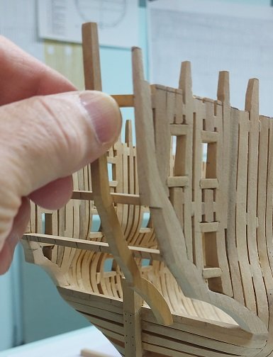
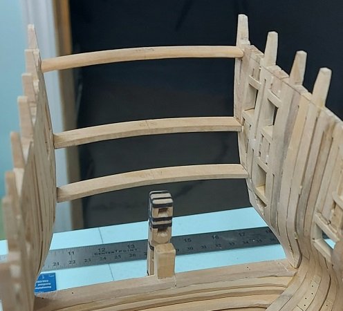
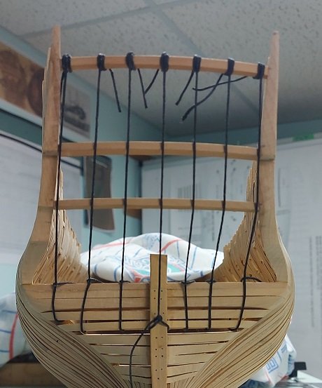
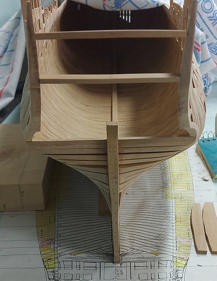
There are three transom beams in the upper half, two mentioned above for the Roundhouse and Quarter Decks, and a third at about the height of the top of the rudder. I managed to get these three temporarily installed but had to use PVA as the rubber cement would not hold up to what I did next. I tried marking the positions for the lights (windows) but was having trouble envisioning it all. To make it clear for me I tied some black waxed upholstery twine on the upper beam with a clove hitch and then to the wing transom with a simple bend as the wax seems to grip and hold it. They were equally spaced at the top beam and then again at the lower beam (needs some minor adjustments again) and now I can see it developing. Once I have it in a final position I can mark these on the beams with a pencil and then pop off the beams to cut the notches in them. Before I do that I think I will make a few cardboard templates for some of the pieces. It is hard to see the fanning of the strings in the photo but the upper (1st or Roundhouse Deck Transom) beam they are spaced at about 1/2" and the lower (3rd) beam about 5/8".
-
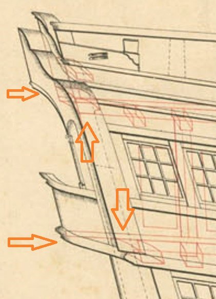
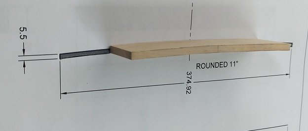
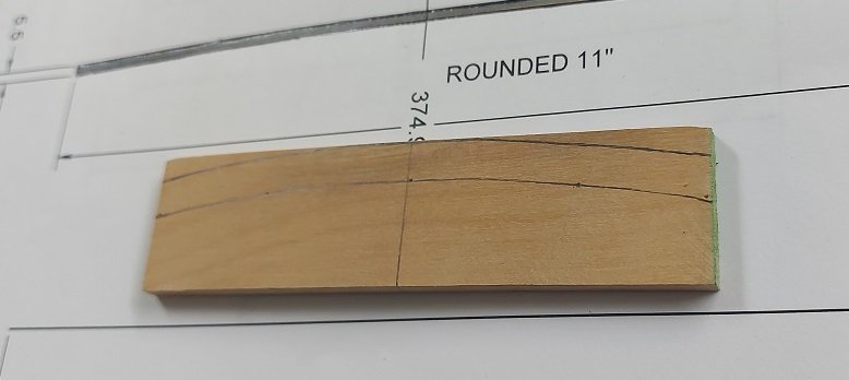
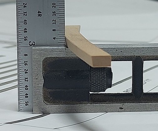
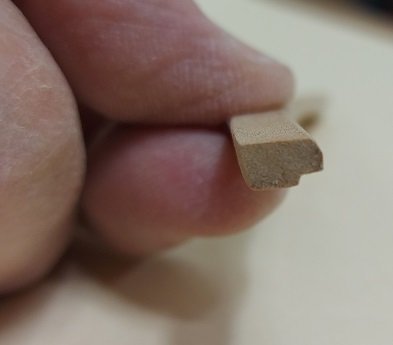
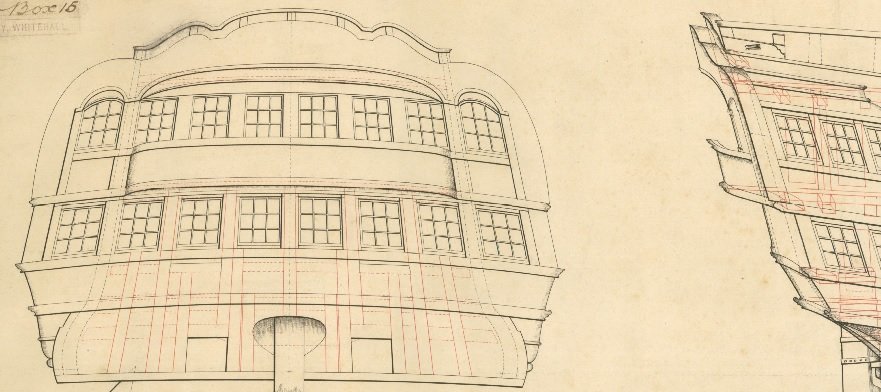
I made the Roundhouse Transom beam yesterday and decided to redo the both of them as the second attempt should be better now that I'd learnt something. Below is the plan showing the transom beams. The Roundhouse (or Poop) Deck transom beam is indicated above and the Quarter Deck Transom beam is indicated below. The Round House (or Poop) Deck Transom beam is larger than the deck beams and is located so the deck planks fit in a notch below it. I began with a block of wood and traced the Round House 11" deck rise using the cardboard template I had made. Measured the height, thickness and aft rounding of the beam off the plan, multiplied by 48 then divided by 64 to get my build sizes. You can see it is double the thickness of the deck beam in the plan below it. The rise was cut out on the scroll saw and then sanded on the oscillating drum sander and finished by hand sanding The rounded back shape was drawn on the blank, cut and sanded. The deck planks are 2-1/2" thick per the contract, so I measured the distance the planks slide into it and cut the notch with my micro chisels, scraped the step out with a square mini scraper and passed some sand paper over it The aft face was bevelled to 8° to match the stern timbers by tilting the table on my disk sander and running the part over it. The forward face upper corner was rounded off with sand paper and all corners were softened similarly. The beam was longer than necessary. I made a length cutoff template with two pieces of cardboard held to overlap each other while running against the inside edge of the frames and taped them together. The beam was cut off a wee bit longer and sanded to just fit with minimum tension created by the frames springing back on it. Then I followed a similar process for the simpler Quarter Deck Transom beam. It sits below the 3" thick deck planks. Both the Roundhouse and Quarter Deck Transom pieces will need to be notched to receive the various vertical stern timbers. I am thinking I will rubber cement the transom pieces in place and then mark off the transom timbers. I have to check for the umpteenth time that I have my deck heights located properly first.
-
Golden Hind by Rock_From_Korea - 1:48
AON replied to Rock_From_Korea's topic in - Build logs for subjects built 1501 - 1750
Well done! -
Seats of Ease
AON replied to stuglo's topic in Discussion for a Ship's Deck Furniture, Guns, boats and other Fittings
Yup. I will dig it up this afternoon and PM you. -
Quarterdeck beam cut, shaped and dry fitted. I will work on the roundhouse beam tomorrow(?). Once I have all the horizontal beams made and dry fitted I will work on the vertical beams. At the point I will cut the notches for them.
-
Actually yes y'all are. I'm not crazy. But what ever I am, I'm in the best of company!
-
The wood has been in my basement for about 10 years so it is aclimated. I won't throw it out because it is good wood... just not for this project. I will do it over.
-
Yup, I've been studying your build and made a cardboard template yesterday afternoon!
-
reloaded. Hope that works.
-
Don't be talking about the Mrs and my wood. 😲
-
Yes Druxey. So it is like in religion ... t'is a mystery? Hence I ask the masses here as I hope for a light to help understand and hope for a full recovery so I can reassemble the original pieces properly.
-
Hmmm.... I can see them. Is anyone else not seeing them?
-
Finally have the doorway cills installed. What a pain in the butt that was! Not very clean looking.... but my best effort. Now I am trying to imagine how to make the beams that go across the stern (side to side) as they curve outwards (aft) and have a curve upwards (rise in the deck) and are notched. The notches are for the vertical stern beams that are sloped aftwards making the notches sloped.
-
Well that got your attention! I have a hard maple wooden frame 24" x 30" with four corner tongue and groove joints. They were glued with yellow PVA carpenters wood glue. I had to take them apart so I wrapped the corners in cloth, soaked the cloth with 91% Isopropyl (rubbing) alcohol and wrapped that in plastic wrap so the alcohol would not evaporate. Left it overnight. Next morning each joint came apart easily. Cleaned the joints of residual glue and dry fitted them back together. The tongues are 3/16"shorter when they were originally flush to the outside of the grooves. This logically seems like shrinkage... due to the Isopropyl alcohol(?) I have not experienced this before in model building as the parts are so small (not 24" x 30") so I guess it was simply not noticeable. I soaked the tongues in water and left them 24 hours. Now they are each about 1/8" short. Has anybody experienced this before? How long will it take to recover? Will it recover?
-
Seats of Ease
AON replied to stuglo's topic in Discussion for a Ship's Deck Furniture, Guns, boats and other Fittings
Speaking of punishment, I was surprised to read a paper explaining that punishments were not immediate. Charges would be laid but the "trial" would be days, or weeks afterwards, giving the offender ample time to think about it. Then when the trial was over and punishment awarded (what a strange term for it) there would be another delay of weeks or months afterwards. I also read that the cat-o-nine tails was tied by the offender and used on him for his punishment alone. It rarely tore up the skin as depicted on movies but did leave the fellow severely battered and bruised.... I imagine akin to going too many rounds with a prize fighting boxer but your hands are tied to upright standing grating so you cannot fight back! Not something I'd want to test and prove. I had enough as a youngster having to go fetch my fathers wide leather belt and getting my own version metered out too many times on my bottom. I was a troublesome lad, but grew out of it.


