
HOLIDAY DONATION DRIVE - SUPPORT MSW - DO YOUR PART TO KEEP THIS GREAT FORUM GOING! (78 donations so far out of 49,000 members - C'mon guys!)
×


AON
-
Posts
2,863 -
Joined
-
Last visited
Content Type
Profiles
Forums
Gallery
Events
Everything posted by AON
-
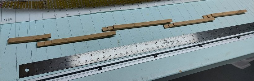
 Went back to the build contract to get the proper sizes for the various gunports as a triple check. Gun Deck 3'-3" wide x 2'-8" tall... except the aft most which is 3'-4" wide (I don't think anyone will notice 1" difference at 1:64 scale) Upper Deck 2'-10" wide x 2'-8" tall. (There will also be two in the beakhead and two in the transom at a later date) Quarter Deck 2'-8" tall x 2'-5" wide Forecastle 2'-8" tall x 2'-5" wide Roundhouse The contract doesn't give dimensions but they measure 3'-0 x 3-0" on the plan Port Cells: (Upper and lower) are said to be 7-1/2" deep (through the frame) on the gun deck and 6-1/2" deep on the upper deck, and "put in with a bill as done in the King's yards". They do not give a height but they all measure 8". The "bill" angles are 30°-60° and 120°. So I created and printed paper templates of the three sizes that I will glue to stiff thin card stock and cut out the outline to be used for tracing. There is an dimensioned 8" long line provided to the right to check the scale when printed. My intention is to hold the template at each marked location and trace the shape in preparation for cutting through the frames. I will need to practice this (tracing, drilling, sawing) on a dummy frame setup first to get comfortable as I am anything but comfortable with the idea at the moment. gunport templates-Model.pdf
 -
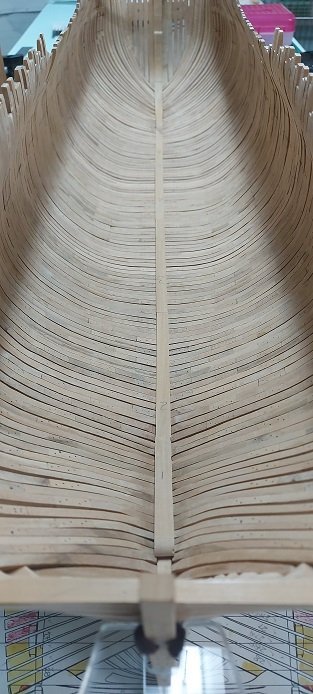
Got the gun deck and upper deck gun ports marked off. Marked off the top timber heights. just have the forecastle and quarterdeck gunports to do. Made the keelson pieces and dry fitted them on the floors and aft deadwood.

-
We called it "a round tuit" because it would get done when we got "a round tuit".
-
1:64 scale figures
AON replied to Dave_E's topic in Discussion for a Ship's Deck Furniture, Guns, boats and other Fittings
You can get some 1:64 scale figures at the NRG Store https://thenrgstore.org/collections/model-figurines/products/seaman-13 -
The show is called The Craftsman. His name is Eric Hollenbeck of Eureka California. It is on DIY on the Magnolia Network, Sundays from 11am to noon Eastern Time
-
starting marking heights I've got the four hawse hole locations marked (at two per side) and six gun deck gunports marked (at three per side) I measured off the original 1:48 plan x 48 / 64 to get my scale measurement. Double checked that to my 1:64 plan. Then marked them on the model. I use a soft "preacher pencil" to mark the four corners and a flexible ruler to hold tight to the curve of the frames and connect the dots with a line. I learnt the term "preacher " versus "farmer" pencil yesterday morning on television watching the master woodworker from Eureka California. A preacher pencil has a fine point to mark the truth or true location. A farmer pencil has a dull point to mark a wider line as a guide for cutting with ease allowing a bit of wander. Both have one thing in common.... an eraser on the end! He cracks me up. Below are a couple photos of my using my height gauge. It can also be used inboard.

-
Ahhhh! I see it now! Book Volume II Chapter 8 3D Figure: 8.34_Forecastle_Bulkhead_03 Thank you
-
I thought it was sealer!
-
Do you have a reference image (drawing, sketch, photo) that you are building to that shows this relationship you can share?
-
Anchor line size
AON replied to Dave_E's topic in Discussion for a Ship's Deck Furniture, Guns, boats and other Fittings
BE Fine for tables that read "Circumference" in the heading but watch out for descriptions of calculations that read "Diameter" and the result seems about 3 times too large. -
Anchor line size
AON replied to Dave_E's topic in Discussion for a Ship's Deck Furniture, Guns, boats and other Fittings
As said in a post above, be aware that when they wrote diameter they meant circumference. Why? I have no idea. They invented the language so I imagine diameter meant something different in that time frame. -
I think my hands would be the only things getting taped 😱
-
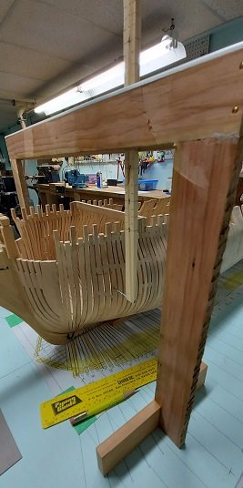
Well I believe this portion of fairing the hull has been completed... and I cleaned all the dust up in the shop. I will start remarking the timber tops and gunports next week as this weekend is full of ship model club meetings (Friday, Saturday and Sunday) and our baby boy turns 40 so there will be a family gathering and spirits will be partaken of. When I start I'll be measuring thrice, then checking yet again because last night I dreamt I cut a hole in the wrong place. YIKES 😲
-
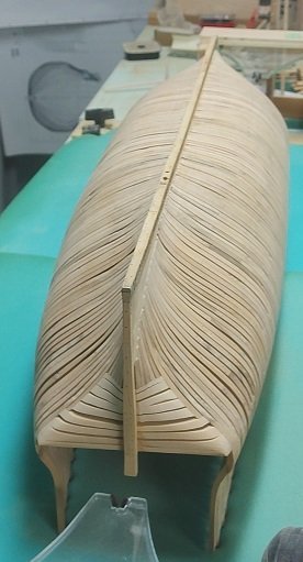
I did manage to get into the shop and determined, though it is looking fine, I am not quite done yet. Other than that, we were surprised with temperatures just shy of 20°C (it reached 19.7), and finally a good abundance of sunshine... so yard work was called for. There will be plenty of time for more sanding... rain is predicted.
-
Only my cant frames without gunports wobbled fore and aft. Everything else was quite stiff. I attribute this to the number of chocks i had installed. I'll be spending a few hours in the shop after lunch. We will see how I feel about it after that.
-
Working on fairing inboard. I'm left with the same nagging question: "when is it enough?" My wife visits me and asks: "will anyone see that?" My response: "I will know." There was this look, after 46+ years I know it well, she left the room. I think I'm done, but someone suggested looking with different illumination. I'll look with fresh eyes and a different light source tomorrow. (God please let me be close)
-
Yes. I imagine it might have happened. But most sailors would have remembered where they "parked the car". It definitely helped the new crew. It is the same reason why they had signs with images over the shops in town. People recognized the image but couldn't read the letters. I imagine some well bred person decided to standardize the figurehead.... cheaper to make than the one of designs. Probably got a bonus, raise, or even a promotion for it. A decision made without thought of consequences. I believe the story because something very similar happened to me once.
-
I must admit, I find that I get some strange comfort and feeling of satisfaction passing the palm of my hand over the smooth hull. Makes me want to do it again, and again. Then I look at the inside and that old dreaded feeling comes back, 'damn it, there's more yet'. Gary - I've never heard or read about using broken glass.... seems like something I should steer well clear of. Phil - if you only knew the struggles I am having trying to undo 55 years of saying Bell-air-o-fon. Why we all did this is beyond my comprehension, even after we were told we were wrong by one person that knew better. It seems so simple to say it correctly now when I look at it, but my brain doesn't want to go there. That is when I realize the struggles of the sailors back then that couldn't read and were trying to say the word. Did you know one reason for ship's having figureheads was because most sailors couldn't read so wouldn't otherwise recognize their own ship!
-
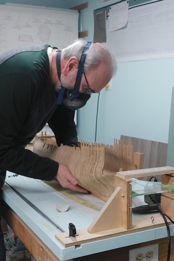
I've got the outboard side of the frames 90% done. Just need to finish them with a few finer grades of sand paper. I will start on the inboard side Wednesday.
-
1:64 but your right.... where's the fun in having someone else get mad and start throwing stuff around the shop for ya. 😏 Can we get a view from the far corner to see the back and other side?
-
Holy crap that looks like a real working stove. Great job! (will you do mine?)
-
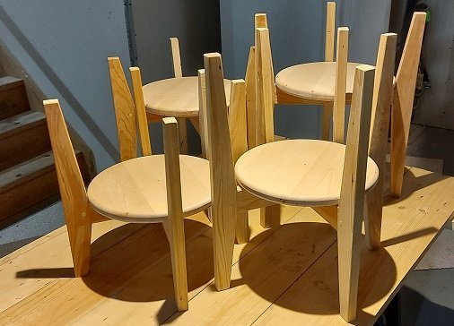
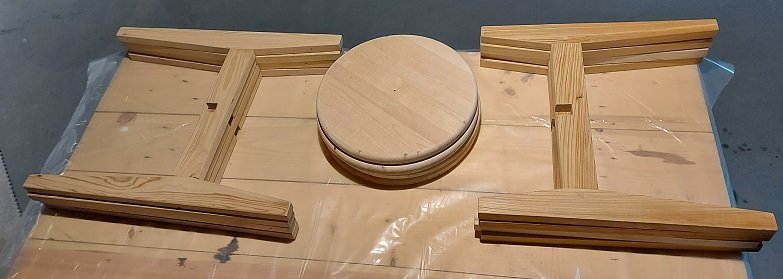
So the wife saw these wooden plant stands on Amazon and I said "I can make that out of my scraps cheaper". So I did... I made a set... and I went one better and made a second set slightly taller. They are collapsible for storage and reversible to vary the plant height. What was it they said: If she doesn't find you handsome, you had better be handy! Now back to sanding my hull.

-
...and possibly the final word with regards to the correct pronunciation... https://pronouncebee.com/hms-bellerophon-1786/
-
Can't wait to see what you're building!


