HOLIDAY DONATION DRIVE - SUPPORT MSW - DO YOUR PART TO KEEP THIS GREAT FORUM GOING! (89 donations so far out of 49,000 members - C'mon guys!)
×


AON
-
Posts
2,867 -
Joined
-
Last visited
Content Type
Profiles
Forums
Gallery
Events
Everything posted by AON
-
 As a sea cadet we said Bell-air-a-fon. But a crusty old RCN (ex RN) Commander once corrected us saying it was Bell-er-o-fon just like it is spelt. I am sure the Greeks have the proper pronunciation.
 -
Thank you Druxey. I believe I tapered the stem from keel to knee per the dimensions in the contract but that was some time ago so it is worth checking again.
-
The Fully Framed Model (6th Rate), vol 4, pg 44 - served all over The Anatomy of Nelson's Ships (1st Rate), pg 226 - seized at the bight at the heart and another at the foreside of the hole at the in the knee and a third at half span between the other two. Historic Ship Models, pg 276 - the two parts were seized together in several places
-
hmmm I'm finding the bobstay on some models has the two parts of the one line served (wrapped) so that it is essentially one line. This would mean it would clear. Anyone know more about this? I will keep looking.
-
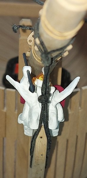
So I am merrily moving along at a snails pace cutting thin strips with my new Byrnes table saw and installing chocks between frames when Flyer posts he noticed an issue with his bobstays interfering with his figurehead in his Bellerophon kit build. The arm broke off of his and he glued it back but possibly not in the same position. Even though his figurehead is different than mine I immediately thought I might have a similar problem and I'd best check. So I installed my bowsprit and figurehead and dummied up a couple of bobstays and there it was, the lines were bent inwards at Pegasus' hooves and lower fore legs. When I get the nerve to try and clean up the horse's head I'll thin down the hooves and legs. I can possibly thin down the stem a little to help create minimal clearance.

-
A few months?!? 🤣 I work at the speed of dark... very slowly. It will be many many months before I get anywhere near that point.
- 366 replies
-
- 1
-

-
- bellerophon
- victory models
- (and 2 more)
-
Now you've got me worried.
-
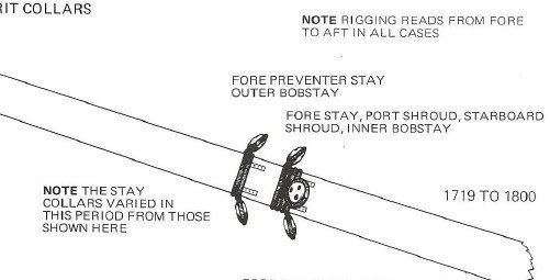
Found it! Of course back then I never thought of recording the source. Once again, this likely doesn`t apply but it is interesting how simple it all was.
-
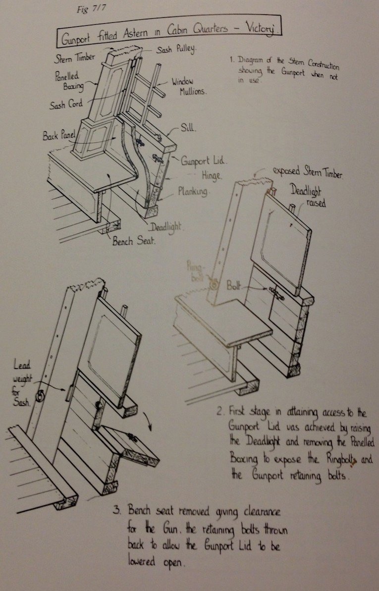
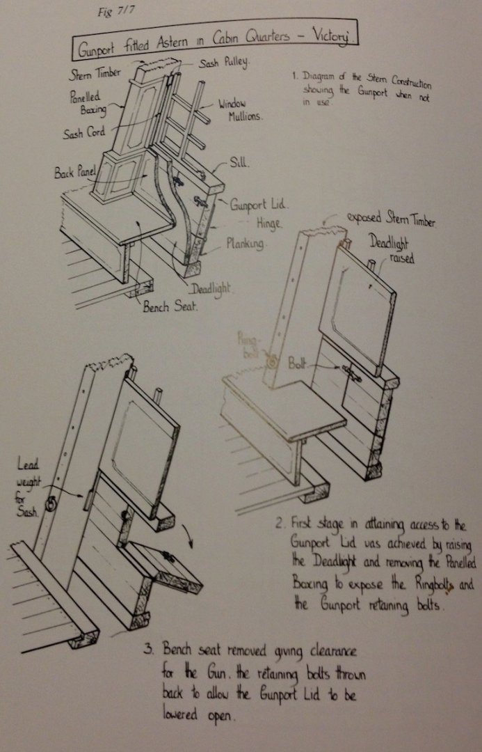
George What an interesting question. I was cleaning up my computer the other day and came across an image of the Victory's chase gun ports. It likely does not apply to your build but it was a fascinating sketch. I was so glad I kept it and wondered how I might have forgotten about it. Now, do you think I could find it again? It showed the lights (windows) above the removable bench that ran across the bulkhead. The deadlight or wooden covering that raise from below the lights, between the bulkhead and the bench via lead weights, a line and pulley on each side. The bench would be removed and the deadlight raised to reveal the chase port which was locked via two sliding bolts, one to each side, like you might see on a fence gate or old pantry door. I wish it would show itself again. Alan
-
Thanks for asking this question. The answer has been filed away for future use!
-
Don't let the rank go to your head. We all know the spouse is the Admiral. 😇
-
Good morning John D. I've looked in both The Masting and Rigging of English Ships of War by James Lee (pgs 49 and 50) and Rigging Period Model Ships by Lennarth Petersson (pg 20) and both suggest the Bobstays were rigged differently than your plan. Rather than a block and tackle system they suggest a collar (strop) around the bowsprit up against cleats and utilizing a deadeye block or closed heart (before 1840) per Lee. He suggests the deadeye block was preferred. The rope feeds through the hole in the Stem and both ends are eye spliced. The other end near the bowsprit would have another matching deadeye block or closed heart. A lanyard is wrapped around through both deadeyes to haul the bobstay tight and is then secured by possibly wrapped around the lanyard loops and tied off with a couple hitches. Petersson shows a closed heart but Lee says the deadeye was preferred. And this is the problem with kit plans versus historical accuracy. If you use a block and tackle as your plan suggests, I believe the running end normally would be secured somewhere accessible to the crew and secured there as opposed to wrapping it about the tackle loops and securing with hitches. Now as the captain you get to chose what to do. No one will question you.

-
You have quite a talent. If I attempted that there would be a puddle on the table top.
- 419 replies
-
- 3
-
-
- Victory Models
- Pegasus
- (and 2 more)
-
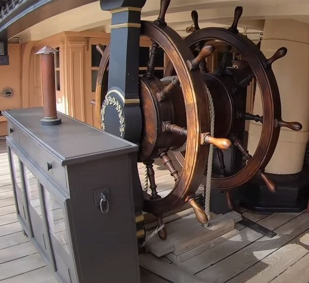
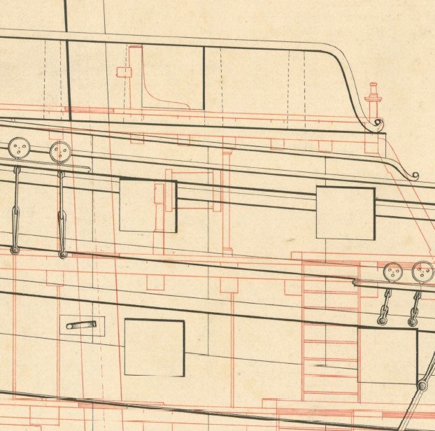
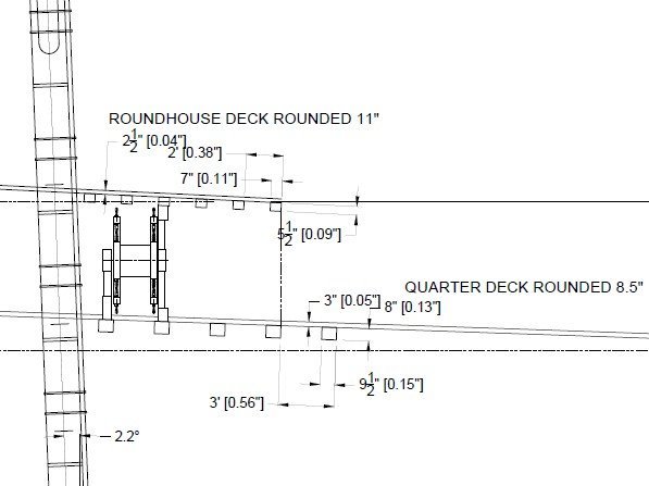
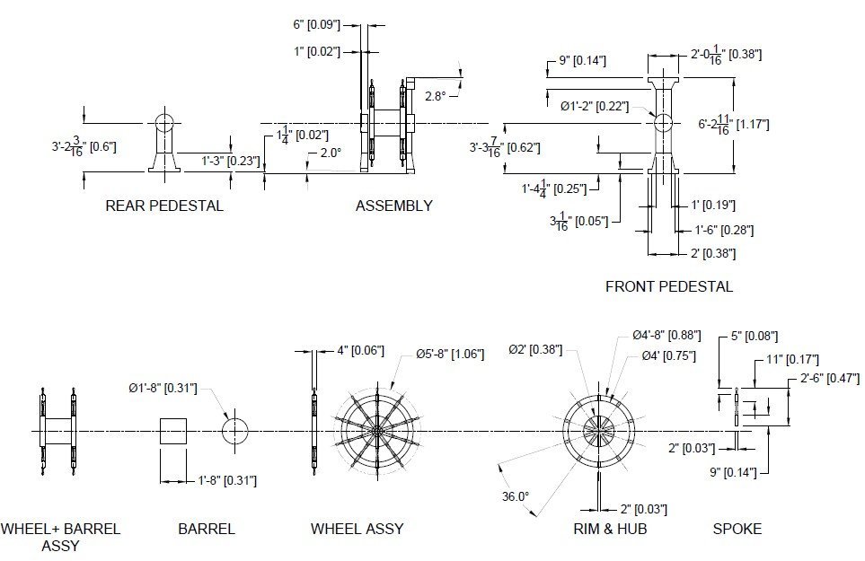
During my downtime I did some research into the ship's wheel. Seems it was very much like the Victory's. A double wheel with a tall fore pedestal and a short aft pedestal. HMS Elephant plans (above) and HMS Victory wheel (below) So I drew it up to fit between my decks and forward of my mizzen mast. Assembly between decks (above) and details (below) Then I drew up some details so when I need a change I can chose to work on my fore or mizzen lower mast and trees, painting/asembling my 74 guns, or the ship's wheel. It is nice to have options.
-
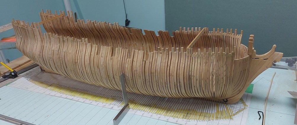
Thank you Druxey, Pat and Kevin.... and others for the "likes". It is encouraging to see people are interested even though I move quite slowly. As I've just completed my third day of recovery following another needle in the eye I am now allowed back in the shop to make dust. Before I do that, my plan is to pencil mark all the remaining gunports (triple checking deck heights) so I can install chocks (spacers between the frames) above and below them. When this is done the whole works should be quite stiff but I will also install a a couple cross braces athwartships on a couple top timbers for additional support. That is when I will begin sanding inside and out... unless I decide to cut out the gunports first and install the upper and lower sills. This might be the smart move as the locations will already have been marked in pencil and not sanded off only to need to be marked again. I've got time to chew on this a bit.
-
Well it has taken me quite awhile but I have finally arrived to this milestone. The last two frames went in early this morning... and everything looks much better. Now to finish marking off the gun port locations, install chocks, etc., etc....
-
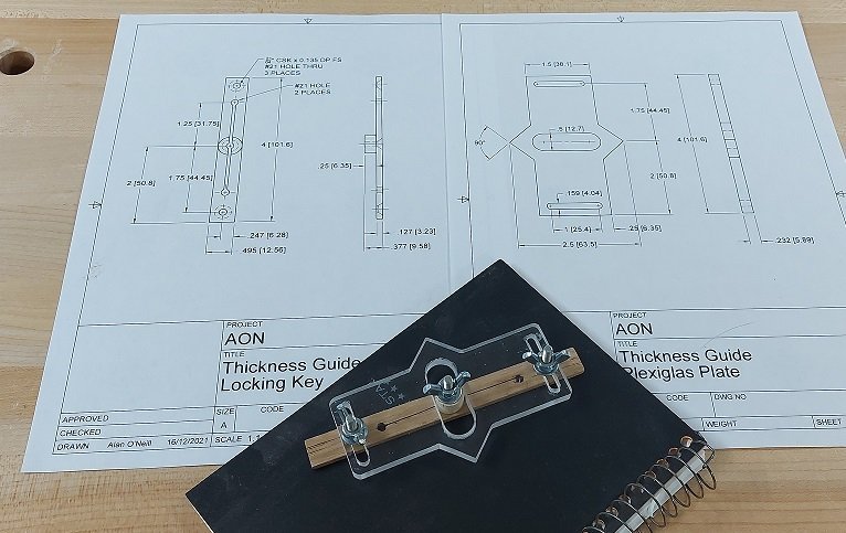
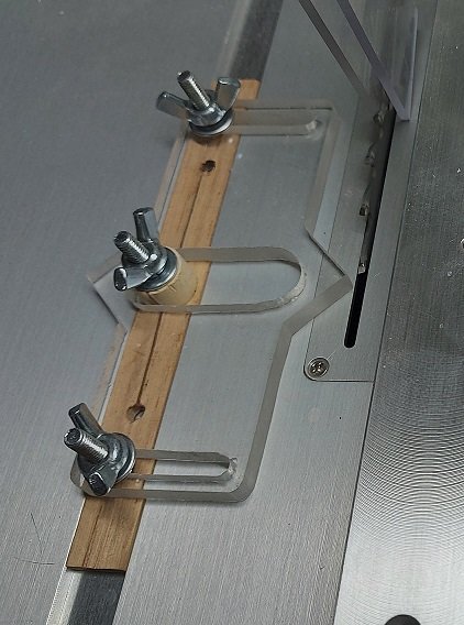
All my staining and sealing of the library donor wall leaves is done. So I've begun the rope work, making the tree branches with 1" and 2" rope, sailmaker's and common whipping of the cut ends underway with 2 oz. waxed twine. So that is keeping me busy. I had to remove a few of my frames on my build as they weren't quite right and I felt I could do better. Presently assembling the dead flat frame. I had attended the NRG seminar on table saw safety and Kurt had showed us a simple thickness guide for the Byrnes table saw. I had also attended a virtual meeting of the Society of Model Shipwrights (UK) and John Garnish had showed us his version that employed separating the key lock from the guide adjustment locks. His guide had a wheel on it where as Kurt's had a "point" and was reversible. So I was inspired to blend the two and below is what I came up with. Kurt announced that the NRG will be selling their simplified version on their website at some time in the near future. I will be buying one to see how mine measures up.
-
Kevin I have the LV miniature chisels and use them all the time, as they are. I would not extend the handle as that changes the pivot and may damage the shank attachment. I also have the LV filter/mask and use this all the time. Being the cheap bastard I am I pop the filters out and take the vacuum to them to get a longer use of them as they ain't cheap. Can you PM me info on where you purchased the Japanese brass clamps as they look interesting. And please let me know how the LV mini scribes work for you as I've been eyeballing them for awhile but wasn't sure they were worth the expense. Thanks
-
Thank you for the kind words Dowmer. As I am retired now, and on a budget, I use the cheapest version of DraftSight for 2D drawings, for which I received a notice that if I did not renew for the next year I would loose out as they are no longer offering that level... I guess I am grandfathered in until they decide that no longer counts. Originally this was free. Nothing lasts forever when there is a buck to be made. For 3D modelling I use the free hobbyist version of Fusion 360.
-
Agreed. Or you might consider making your own scale rope.
-
My lower mast tribulations: I had previously made my lower main mast as per Steels, Mast Making (1794), Volume 1.1, Tables (dimensions) and plates (drawings) 2 and 3. I began creating my fore and mizzen lower masts using calculations from formulae in the same publication while referencing plates 2 and 3. This is when confusions began to arise. Some calculation did not agree with the table figures and the figures did not completely agree with the descriptions. For example, the bibs and cheeks are smaller on the drawing then as calculated. Similar dimensional differences were realized with the main top (platform). So I had to employ "artistic license" and massage the drawing so the two smaller masts didn't outshine the main mast that I'd already made. Then came the length of the front fish. Steels plates clearly show them extending below the orlop deck on the main mast, and not so clearly on the foremast for a 74 but quite clearly on a 36 gun ship, so I added it on my 74 foremast. However there doesn't seem to be a front fish on the mizzen mast. I checked other builds and most don't have this type of detail, or they show the improved shortened and narrowed paunch that came to be about a decade later. I checked my books, the Anatomy of Nelson's Ships by Longridge shows the short narrow paunch from a decade later. AOTS Belona by Lavery (figures H) shows no front fish or paunch at all. Masting and Rigging OESOW by Lee, which are observations on historic models, (section 1, Part 1, page 2) disagrees with Steels plates, stating the length of the older style front fish or paunch on the masts stopped above the upper deck. Then (page 3) states the mizzen mast was not fitted with a front fish as a permanent fitting, but did have a rubbing paunch (?). I decided to make all my lower masts similarly. My mizzen mast being so much smaller would have a less prominent front fish. I also continued my woolding hoops to just above the partners (upper deck) on the mizzen mast, not as shown in Steels. For those interested, below are my drawings for my lower foremast, mizzen mast and their tops. My drawings print on 8-1/2" x 11" (A size) sheets of paper and are at 1:64 scale. Each mast drawing is on two sheets that need to be taped together. The "splice line" is clearly identified. fore top layout.pdf mizzen top layout-Model.pdf Foremast Cheeks+Fish+Bands - sh 1 of 2.pdf Foremast Cheeks+Fish+Bands - sh 2 of 2.pdf Foremast Layout - sh 1 of 2.pdf Foremast Layout - sh 2 of 2.pdf Mizzen Mast Cheeks+Fish+Bands - sh 1 of 2.pdf Mizzen Mast Cheeks+Fish+Bands - sh 2 of 2.pdf Mizzen Mast Layout - sh 1 of 2.pdf Mizzen Mast Layout - sh 2 of 2.pdf
-
Tacking and Wearing A well spent 8 minutes and 54 seconds Thank you.
-
Very clear instructions and very realistic results. Thank you Tom.
-
I suppose she simply needed to pass periodic inspections during the build and so long as she was sound and not less than the specifications she was " good enough"!