

AON
-
Posts
2,580 -
Joined
-
Last visited
Content Type
Profiles
Forums
Gallery
Events
Everything posted by AON
-
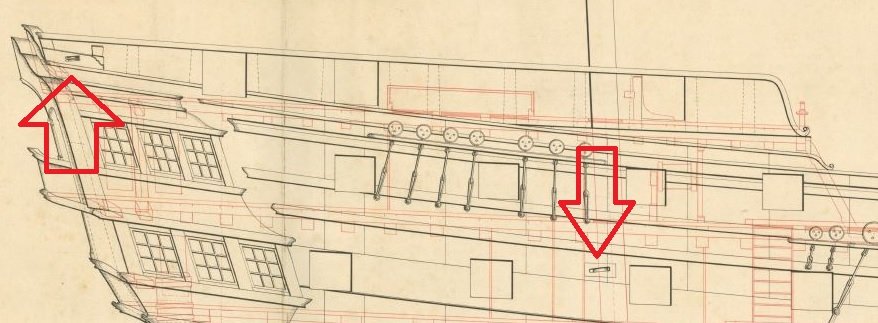
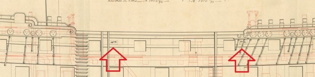
 If you really want to go nuts there is another set of sheaves further forward. I can measure these off the print for you if you like.
- 364 replies
-
- 4
-

-
- bellerophon
- victory models
- (and 2 more)
-
If you've only done the pair I am not sure you have gotten them all. This is from HMS Elephant... same as the Goliath... same as the Bellerophon.
- 364 replies
-
- 4
-
-
- bellerophon
- victory models
- (and 2 more)
-
maybe consider some blackening practise runs on some of the drops (cut off pieces).
-
Seems these are more of a guide line than a hard and fast rule.
-
hmmmmmmmmmmmm
-
Quite the conundrum! I've no answer.
-
Of course you are correct... about the trucks not the view of the horse. In my haste to transpose the selected information without recognisable plagiarism I reversed the diameters of the trucks. An unforgivable error. Correction made. Possibly you might moonlight as my proofreader?
-
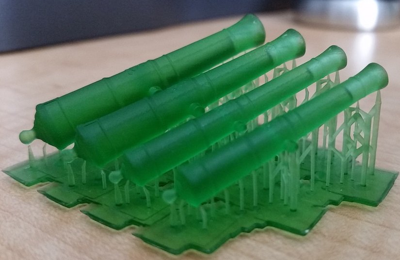
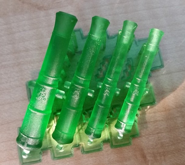
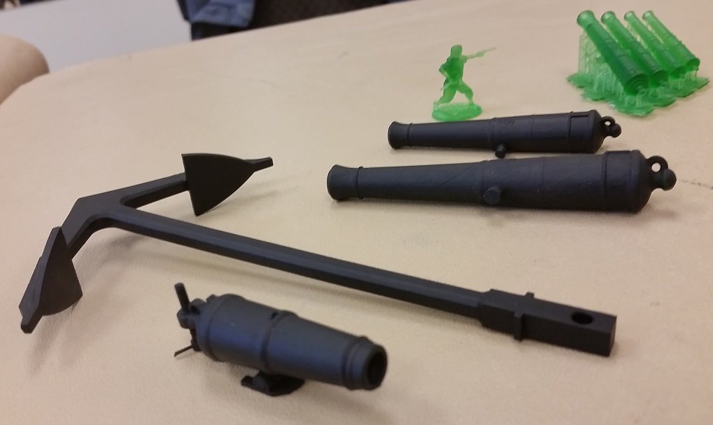
This weekend, after seeing a set of four sizes at 1:64 scale, I commissioned one of our local club members (Model Shipwrights of Niagara) to 3D print me a full set of 74 guns to be distributed as follows: 28 each x 32 Pdr ( 9.5 ft - 55 Cwt) - Lower Gun Deck 28 each x 18 Pdr (9 ft - 40 Cwt) - Upper Gun Deck 14 each x 9 Pdr (short at 7.5 ft - 24.5 Cwt) - Quarter Deck 4 each x 9 Pdr (long at 8.5 ft - 27.5 Cwt) - Forecastle These will be created with his SLA UV acrylic liquid resin 3D printing machine made by Any Cubic Photon. My machine cannot achieve this type of finish and detail at this small scale. Below are photos of the proofs brought to our meeting on Sunday. They are quite smooth, exactly to scale complete with every detail. They can be sanded and accept flat black acrylic paint as he brought in his test pieces. These will go into storage! I also got my hands on a few copies of the Marine Models Magazine dated 1935 - 1939. In some of the issues were very interesting articles about ships' armament written by Mr. A. P. Isard. I will try to describe some of the points I found most interesting.... Ship's guns were originally brass but when replaced with iron they saved 160 tons of weight. The original Royal Navy foundrymen of Kent and Sussex had a steep learning curve prior to achieve trustworthy castings (that didn't burst), smooth true bores (that didn't bend up or down). Prior to the properties of coal being appreciated there was a fight between foundries and shipyards over the trees. It took some time before they managed to get the gun powder mixture correct which saved some lives, but with the increase of quality of gun powder came frequent destruction of carriages. The earliest cannons had no trunnions. Once added they were cast inline with the bore but were later lowered to provide better support and ensure a downward pressure on the quoin upon recoil. Monsieur Gribeauval of France introduced many innovations that were over time adopted by the English Royal Navy: big wheels, iron axle trees, cartridges, elevating screws... all being, where possible, interchangeable. in 1778 the Carron Company introduced the carronade. Merchantmen readily adopted it but the Royal Navy needed to warm up to it for some time (and in many cases they never did!). It was lighter weight, required less powder and a smaller gun crew. With its heavier ball it was more destructive at close quarters. One of the Royal Navies biggest objections were poor fitting balls. Eventually the bores were re-engineered to suit the sizes of the cannon balls. The carriage wheels were called trucks with the aft being smaller then the foreward. This compensated for the camber of the deck and dampened the recoil when the gun was fired. If the gun was place directly aft the position of the wheels would be switched resulting in a raised aft end for the same purpose. The crew was trained to use the roll for the ship to make the gun recoil uphill. The trucks were made of hardwood so as not to damage the deck. Heavier guns had the trucks made in two laminated layers with the grain of one layer being across that of the other. Breech ropes stretched and the two ring bolts acted as guides. Carronade wheels tracked together (inline) whereas the long gun trucks did not. The force of the recoil on the breeching of the long gun caused the weapon to jump; raising the fore trucks off the deck. Available space on the deck did not allow the aft trucks to be moved back to counteract this. Eventually they lowered the trunnions to effectively reduce this phenomenon. The tackle secured to the bulwarks on each side had to be precisely adjusted to equal lengths so as to resist the carriage twisting and injuring the guns crew and gear. The random recoil path of the gun due to many issues, not excluding the unevenness of the deck, maimed many a man. Men were also injured by breechings, bolts and sundry fittings flying around the crew. Guns were most dangerous when fired to windward. When fired the trucks would immediately skid along the deck prior to rotating. Wedges (roughed and tarred to increase the friction) were employed under the trucks when fired ahead or astern to counteract the unequal recoil. And as a final entry a quote directly from the articles: "Carriages were, therefore, a matter of experience and experiment, their sizes, strength and weights being nicely balanced with the weapons they were to carry and, like most things about a ship, a compromise."
-
That was part of the image chosen. I would need to search for a better one. Clearly my fault.
-
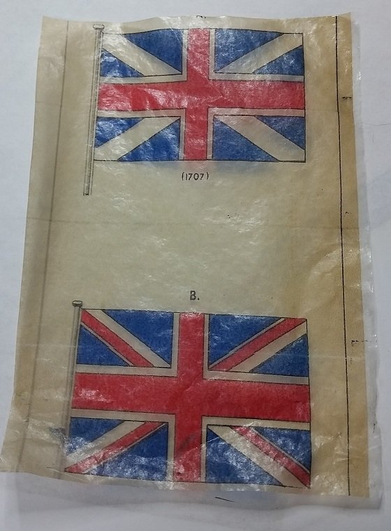
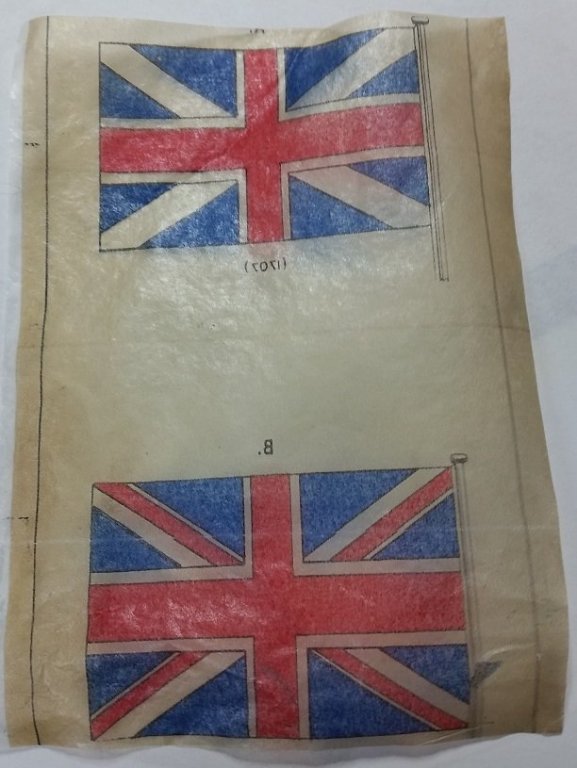
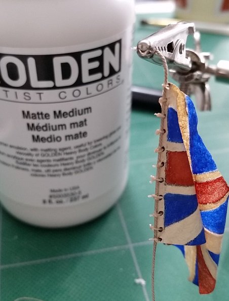
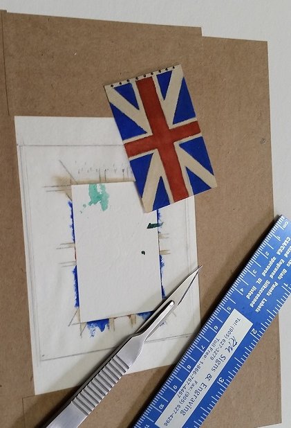
First - I "spliced" in a length to my halyard to make it look proper length-wise. I had to fight the urge to make it neat as a working ship would not be too neat. Second I printed the Union Flag onto tissue paper. Actually, first I marked the bottom end of the face up paper in the printer tray with a small "X", then I printed the jpeg image. Now I knew how to reload the paper. I cut out a piece of white tissue paper (the kind used with gifts) and transparent taped it (top and bottom edges) to the print paper over the recently printed image. I reloaded the sheet back in the printer tray, X side up and to the bottom, and hit PRINT. Removed the tissue paper from the bond sheet and sprayed it with the matt fixative, back side first. Hung it to dry. I find the back side is not as crisp as the front side (not so noticeable in the photo as in real life)and the "matt" makes it a bit shiny... but the biggest loss is any resemblance to open weave cloth. Although the hand painted version on silkspan requires more talent than I presently have, it does better resemble a cloth flag... IMHO. To each their own. I think I will stick to the silkspan painted method. Thank you for the suggestion. I learnt something new today!
-
I'm buggered now. 😣
-
We had a good meeting yesterday. It was brought to my attention that my halyard is short. I will be "splicing" a length, folding it over and tucking it between the staff and halyard to complete it. then it all goes into storage until I am ready to install to the model at which time I will add other missing bits and pieces to the bowsprit and jib boom. I did purchase some tissue paper and will be printing off a flag to see how that looks ... will post.
-
...and sometimes close enough is practical. The hardest lesson I have trouble with is accepting that no one is going to take a caliper to my model.
-
and I was confused when multiple sources would not agree. I'll be watching to see what our knowledgeable members suggest is the reason for Steel's discrepancy It is not a year thing is it? Table for after a particular date and description for before that date??
-
Actually they cut slices from the inner tubes they used to drag the sailors along behind the warship at very high and unsafe speeds when they were not battling at sea. They had so much fun back then.
-
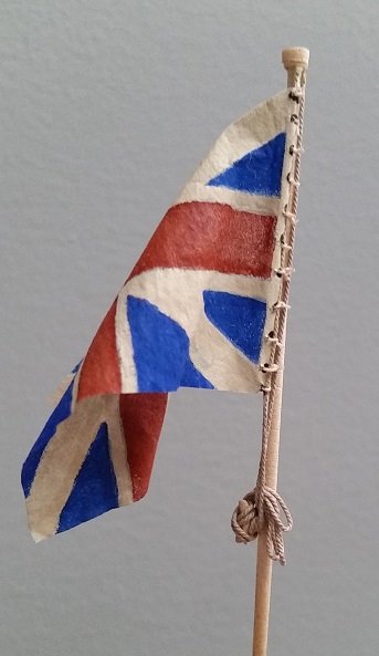
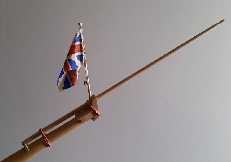
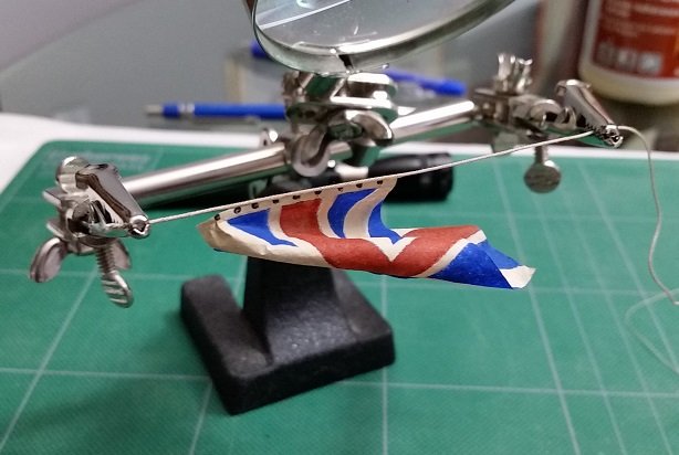
Union Jack and Halyard mounted to Jack Staff and secured with figure eights to cleat. No hitches - it was getting crowded. A touch of glue and she's done. I will be bring this assembly to our local club meeting tomorrow.
-
You took the mystery out of picture posting! It is so much easier now.
-
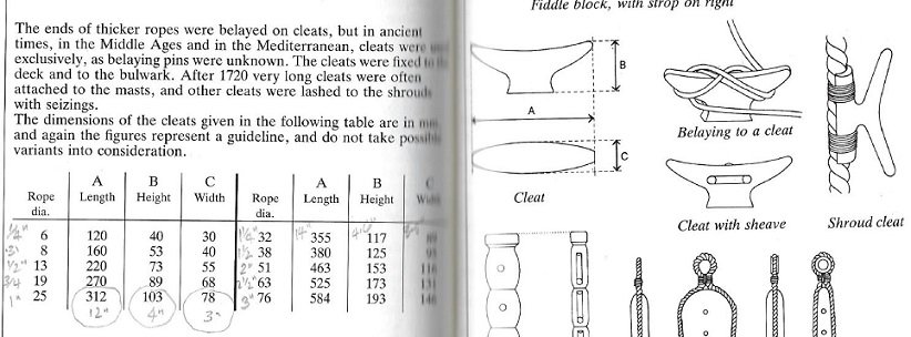
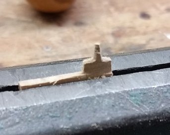
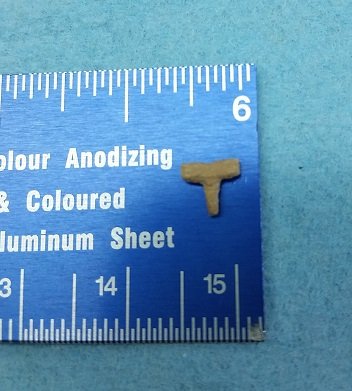
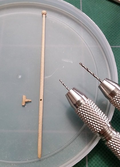
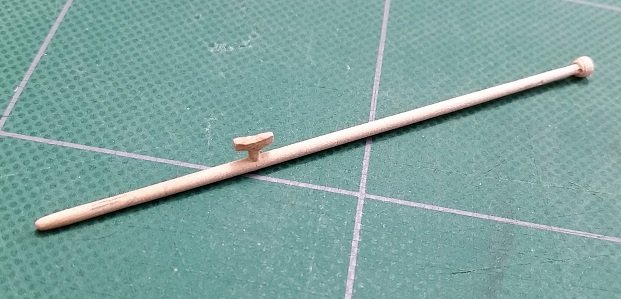
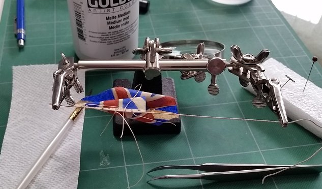
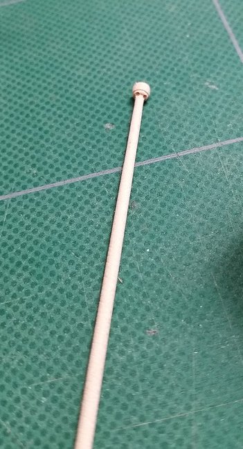
Had to hunt for some dimensions for the cleat and found information in my copy of Historic Ship Models by Wolfham zu Modfeld (pgs 246-247). Clamped a piece at thickness and started shaping it upside down as my first attempt right side up didn't survive. My dimensions are A = 0.215" (0.64 mm) long ; B = 0.1095" (2.78 mm) Tall (peg not included); C= 0.065" (1.65 mm) Thick or wide. The height will yet be reduced to be nearer what it should be. Marked off (to be above the bowsprit cap and below the bottom of the hoist edge of the jack) and drilled out the jack staff to receive the peg and glued the two together assuring it was oriented correctly with the halyard holes above. Letting it dry now before I attempt to cleanup the shape a bit with very fine sand paper while wearing my magnifying goggles. Then I will assemble the flag and halyard to the staff and cleat.
-
Thank you Mark Let's see how it works... The last couple of days have not been good for me and frames. I did help my son pass some trim through the jointer and I have wasted time waiting for gas fitters to connect the radiant heater in my son's garage while he was at work... have to go back tomorrow because the three different lists they made were still short parts. So I secured the jack to the halyard with the marline and sealed it with matte medium which applies white and dries clear. This will also add additional stiffness to the halyard at the hoist of the jack and provide addition adhesion to hold them together. I did not trim them too closely to the halyard purposefully as I want them to be noticed. Possibly I will find time to make a tiny cleat tomorrow. Thank you again Mark! That was easier.
-
I will try that next. I had put them in the box then tried dragging them out to put in the text.
-
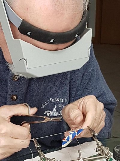
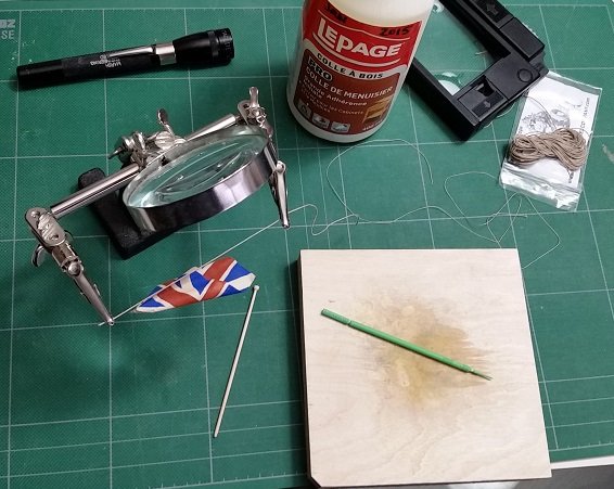
It is Thursday morning and I find the imperfection of my flag is growing on me. It seems to make it more realistic and worn. Yesterday I employed a set of extra hands, found some 1 inch line in my stash and glued the flag to it. I dabbed a fine line of yellow glue to the line and while pre-aligned and supported on a chuck of 2x4 wood I manoeuvred the two together. The head of the hoist edge did not contact the line. After allowed to dry, I moistened the corner with a soft paint brush and water and reshaped it to align with the halyard. Presently it is drying. Once done I will glue this to the line. I managed to drill two fine holes into the truck or cap of the jack staff for the line. As I was concerned with breaking the truck I started with a #76 drill bit in my pin vise and while slowly twisting it back and forth to drill and clear away the chips I sequentially opened it up with slightly larger bits until I reached #70. This will allow me to stuff the line into the hole after I dab some glue on it. I found rope for the marline and still need to make a cleat. And I still intend to print a flag to see how it compares. (and once again my photos are loaded out of intended order but I've managed to drag them intoa proper sequence))
-
I have no idea why my photos get turned or become out of sequence when loaded. I've tried to correct this but possibly I need a sprinkle of holy water to correct the problem.
-
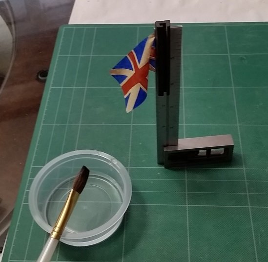
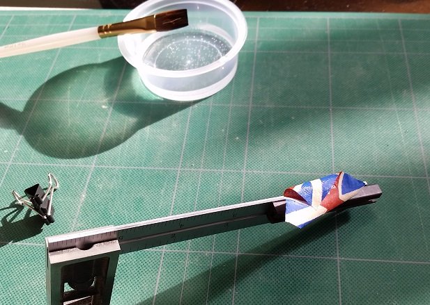
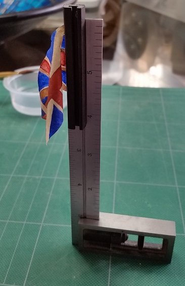
Practically done with this attempt. I am not completely satisfied with my painting and may make another after I purchase some green acrylic paint and a softer white. I would use a finer brush and thinner wash (acrylic paint diluted with water) on any other attempt. I will try the "printed" version on tissue paper for comparison but I feel I will need to add the hoist edge and grommet holes to the image so these are printed also. I'll need to acquire white tissue paper at the dollar store and the fixative from Home Hardware to pull this off. My reference for the grommet holes is Volume IV of TFFM (The Fully Framed Model) pages 121/122, and is clearly shown in the bottom photo on page 203. His reference is Steel - Rigging and Seamanship, Volume II, page 129 (`the jack is bent to the halliard by rope bands of 2 lb of white marline`). 2 lbs is the weight per fathom (6 feet = 1.8 meters) so I imagine this to be something like 1/2" diameter rope. So I did the minor touch ups, marked off 9 inch intervals (equally spaced from top edge to bottom edge) against the hoist edge and added dots to suggest the sailmaker's style sewn grommets (http://www.frayedknotarts.com/sailmaking.html) for the 2 strand marline rope (https://rwrope.com/classic-boat-supplies/tarred-marline-tarred-hemp-twine/) used to secure the hoist edge against the halyard (not the staff as I typed earlier) as the jack was raised with the halyard. These dots were made on both sides using the smallest paper embossing ball burnishing tool (0.03" or 0.81mm diameter ball) that I have in my arsenal. I intend to simulate tying my flag to the haliyard with glued thread so once the simulated grommets dried I made a hole through each using a #74 drill bit (0.0225" or 0.5715mm diameter) which would be about 1-1/2" diameter at 1:64 scale. This is likely too large but I will hopefully be able to coax short lengths of simulated marline through those. I put the plug back in and cut out the jack using a scalpel. I then clamped the hoist edge to a metal square with a magnet, brushed some water onto the flag and put in a primary or initial curl. After allowing this to dry I then wetted the outer portion or the fly quarter and put in a secondary or final curl. I had to set the square on end to allow the Silkspan to retain the shape while it dries. So below are four photos and a short video showing the finished product. Finished product - Union Jack video.wlmp
-
Grommet dots along the hoist side at about 9 inch intervals for loops that held the hoist against the staff. Yes there were toggles (now Inglefield clips) at the top and bottom of the hoist. I would be very interested in seeing images of the captured flags... particularly in this case a Jack

