


AON
-
Posts
2,876 -
Joined
-
Last visited
Content Type
Profiles
Forums
Gallery
Events
Everything posted by AON
-
 go down to post 37 at: https://modelshipworld.com/topic/1133-baggywrinkles/page/2/#comment-627511 he explains how he made them.
 -
image 0037 didn't load the others look fantastic! well done
-
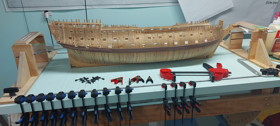
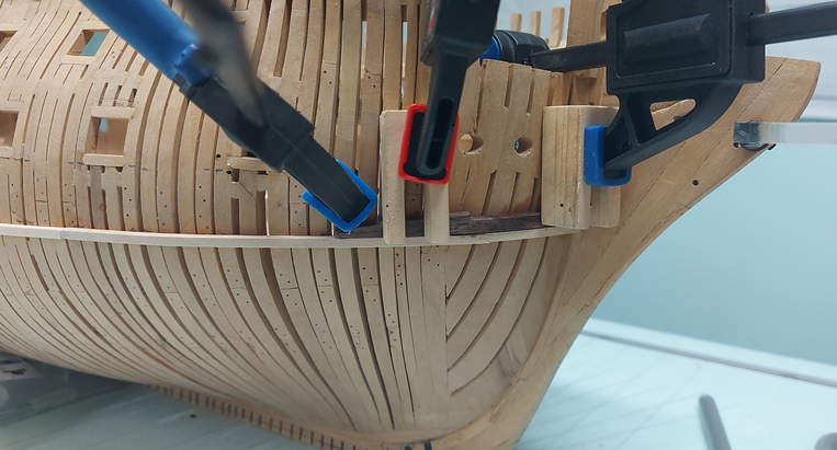
The main wale jig-saw pieces are installed on the stbd side. I've one piece to add to the port side and then some sanding. I think I've done an acceptable job of it for my very first ever (and likely last) time. I found it very difficult, in fact impossible, to make the one side perfectly identical to the other. Human error. The saving grace is you cannot look at both sides at the same time... except from the bow and stern, in which case they seem to match fairly well. I did receive one personal message regarding the my bow: "The sheer should flatten out under the hawse holes as it heads to the bow rabbet." I've looked into it quickly and found my measurements and layout for the underside of the main wale is correct. The width (up/down) expanded a wee bit in cutting out and shaping, and the top side was initially wet and pinched when clamped. The top sides on port and starboard match. I need to go into it in more depth after I get the stern completed. Some adjustments are in order. I am certain there is accumulative error involved in the top side of the wales and the underside of the hawse holes. Some slight of hand may be in order.
-
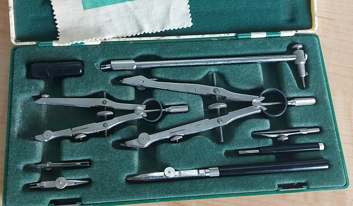
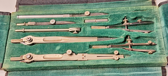
my newer old one is ALPHA Precision (Germany) the older old one is TESCO (Technical Supply Co., Montreal).
-
You can see in the two photos below that to draw straight line the set has a straight handle for one nib. This nib threads onto the handle making it pen like. The other nib options have slots to fit and clamp onto the compasses. The newer set is mine, about 60 years old now. The older set was my grandfather's, circa 1900.
-
This YouTube video shows the pen in use. https://www.youtube.com/watch?v=W3XlJWzvSVM see from 2mins 30 sec to 3 minutes If comfortable loading and using an draftsman's ink bow pen then there is on problem. I suppose this might be easier for some.
-
Getting near the end of installing the main wales. I'll be away from the shop for a few days. When I get back I'll install the last 2 sets and then work on planking the lower transom and sanding the wales to the planking.
-
Looks like a nice spot with easy access. Myself, being situated between two of the of the great lakes (Erie and Ontario), I must regularly remind myself that not all "lakes" are massive. I am think of the phrase from the famous Crocodile Dundee movie: "That's not a knife. This is a knife!"
- 72 replies
-
- 2
-

-

-
- Miss Adventure
- Model Shipways
- (and 2 more)
-
it all came together nicely! does the pond/lake have a name? It is good to be able to walk around and retrieve a boat when things go wrong and she drifts to the other side. ask me how I know.
-
Golden Hind by Rock_From_Korea - 1:48
AON replied to Rock_From_Korea's topic in - Build logs for subjects built 1501 - 1750
some images seem to be missing 1980 and 1985 -
There is an easy way????? 🤔
-
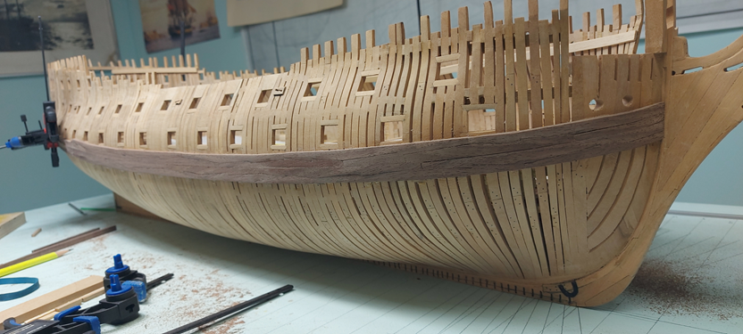
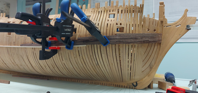
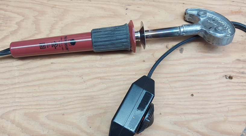
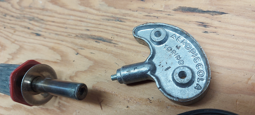
Getting back into it and it is slow going right now. Soaking the pairs in boiling water then clamp them to the frames, one on each side of the ship (port and starboard). Once dry they come off and the soldering iron gets used to remove the spring back. Then they get glued and clamped in place. I am about to lay the wale planks over the flat area, no bending, so that should go quicker. I managed to get the gifted Areopiccola bending head adapted to my soldering iron. I cut off the two tabs, filed and sanded it flat and no sharp edges. Drilled with a #29 bit and tapped 8-32 thread, then inserted a screw, cut off the head and filed that edge. Then just screwed them together. (Thank you Mort!)
-
Druxey Please accept my sincere apologies for not having responded in a timely manner. I have had a very busy few weeks. First I thought I was having a stroke, but after the better part of a day in Emergency I found it was Bell's Palsy caused by a virus and treated with some heavy duty drugs. The right side of my face was paralyzed and I could not close my right eye so it needed to be taped shut to sleep at night. I still have not fully recovered, but my eye is fine and I do not dribble anymore when I have my tea. My lips feel normal but my tongue does not stick out mid face, still slight out to the right side. Then my wife caught a virus (head cold - likely from the hospital) and passed it on to me, so we've both been suffering from that. My throat is still a bit sore but my head is no longer foggy. She is much better also. I hope to be back in the shop later this week. I managed to get the first piece bent, fitted, and glued before everything mentioned above happened. I figured out how to manage the others (a two stage bending process) but have had no progress since. Laminating might have been a solution, but I'll stick to full thickness for now. Keep this idea in my back pocket! Alan
-
Easy to do if a plank with no jigsaw notchings. I don't think I could manage a matching pattern on a curve. I've the one set glued on now and two other sets soaked and clamped presently.
-
I started with the lower most forward piece. Marked off the chamfer to fit to the stem post on both port and starboard pieces. Shaped the first one.... pretty good. Shaped the second one... darn it, I did the inside rather than the outside. Made a new piece and did it correctly. Tried to bend them with a new 30W large round head bender... wouldn't work. Tried wetting it and then bending with the new tool... still wouldn't work. My guess is 30W is inadequate heat for the thickness of the part. I soaked them in boiling water and clamped them onto the frames. I'll use my soldering iron barrel tomorrow to put that little bit more bend to them to seat properly. A member of our club gifted me a Areopiccola bending head but it doesn't fit my irons. The irons have a small threaded hole The Areopiccola head is 10mm diameter and split to slide into a barrel with a 10mm hole. I need to find a soldering iron that will accommodate it. With adequate heat it should work.
-
Hope you right!
-
After getting through a multitude of terribly sunny, warm and blue sky days where I just had to force myself to sit out on the back patio, then having yet another health issue I am dealing with, I finally got down to the shop today. I have my lower guides spot glued and clamped so I’ll be ready to go. I have all but one of the main wale pieces dry fitted on the bench. The one piece needs to be remade. It is not perfect, but I am aware of my capabilities/limitations and can recognize when my “good enough” has been reached. Now to get that last set remade and start getting them on the model!


-
Sitting at my computer, watching yet another wonderful video with my darling wife of very nearly 50 years seated at her computer to my left... then came your comment about keeping your eraser handy to which we both chuckled! Thanks for that too.
-
Don't throw them away. They might get used down the road! 👍
-
Your grating looks damn good to me. The spaces (gaps) should be there.
-
The proper name for the small boat cover or canvas tie down rope is ......... darn it, I forget!
-
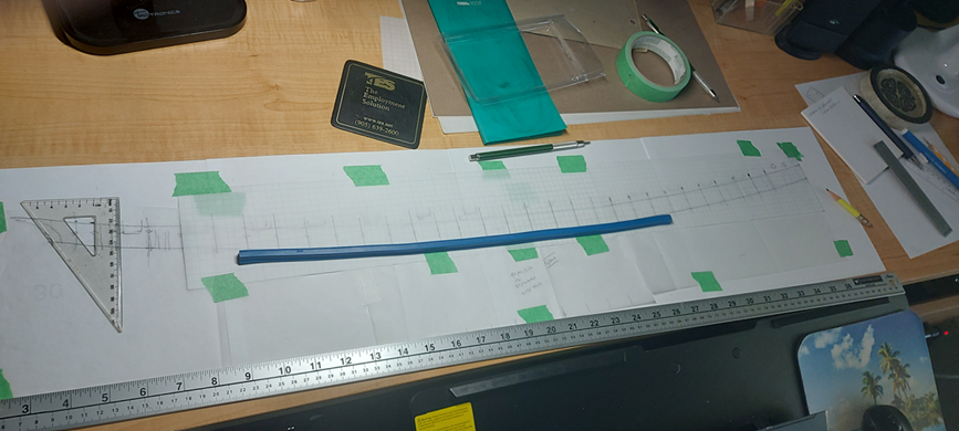
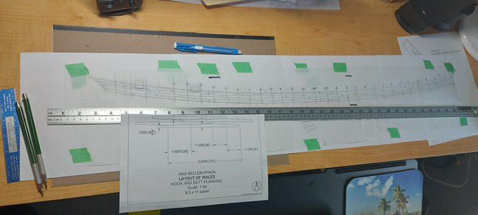
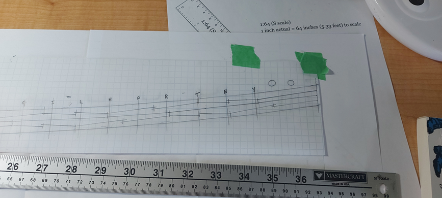
Completed the main wale edition 3 layout with the slightly more complicated double hooks. In the first photo you can see the tools used. Not so obvious is the straight pin used to hold a point of the printed sheet so it could be spun a little to help make it all follow the curve of the wales. I have a flexible curve from my pencil and paper drafting days, works better in this instance than my French curves to make a long gentle curved line. I copied (traced) my original boundaries (taken off the model and onto tracing paper) onto a new fresh set of overlapping tracing sheets. I slide the printed layout of the wales under the blank sheets and went to work with a 2H pencil. You can see the results in the second sheet. On the third photo is the bow layout. Now I have a dilemma. Do I head downstairs to the basement and start cutting and sanding to thickness new stock, and start tracing, cutting and sanding new pieces... or do I spend the last few sunny days of post summer (fall) outside. Tough one!
-
Brandon Plank of the Bottom refers to the planks below the main wales. When I look at my contract it reads similarly for the planks of the bottom. The Berwick (74) main wale planks are definitely longer than 24 feet. Alan
-
Thanks. My contract specifies hook and butt does does not mention length. Looking at 30ft. Presently

