HOLIDAY DONATION DRIVE - SUPPORT MSW - DO YOUR PART TO KEEP THIS GREAT FORUM GOING! (78 donations so far out of 49,000 members - C'mon guys!)
×


AON
-
Posts
2,863 -
Joined
-
Last visited
Content Type
Profiles
Forums
Gallery
Events
Everything posted by AON
-

Leon by Doug McKenzie - 1:300 - BOTTLE
AON replied to Doug McKenzie's topic in - Build logs for subjects built 1851 - 1900
Good evening Doug. I thought I'd watch you, learn and possibly try something easy .... but it looks like there might not be anything easy about ships in a bottle! I might try a submerged submarine! 😃 You must have one very steady hand. Alan -
Correct.
-
I could belive one side was for the Captain and the other side for supernumaries but not necessarily a door inside vs. the other outside.
-
Odd... 9" versus 10"... to save weight. They would start with 10" and spend extra time cutting away 1"!?. The half span is where the strength is needed, not at the ends.... unless it had to do with wood rot.
-
Interesting! Thanks.
-
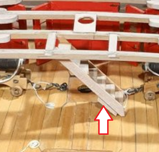
it seems to be attached to the backside of the ladder, behind the closed stringer at the bottom. I put an arrow on the photo to point it out.
-
Silly but practical! 🤣
-
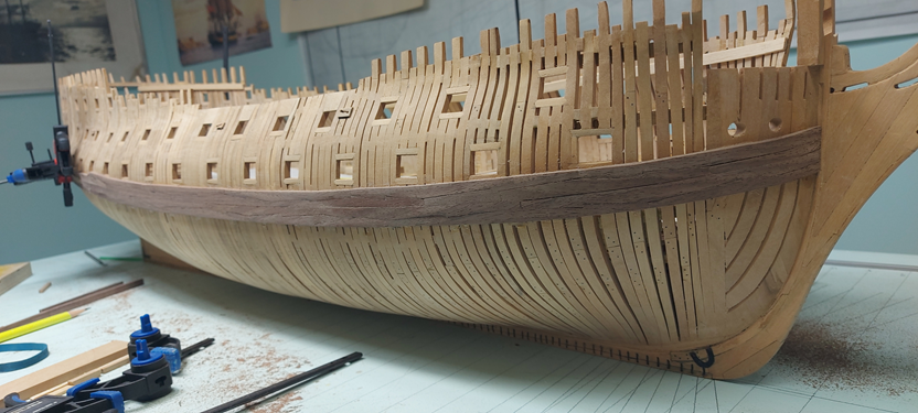
I am presently installing the two strakes above the main wale, cutting my notches in the gun deck beams for the carlings, and trying to plan how much of the hull exterior I will leave exposed.... and the lights went on. Finally! About two years ago I struggled to complete the counter timbers at the stern (posting #1512 on Feb 21 2023). Something didn't make sense and I just couldn't put my finger on it. I followed the detailed instructions I'd found in a reference book but the balcony seemed quite shallow. The quarter galleries had two doors on each side at the upper level. Why would they need two doorways into the one toilet facility? I discovered that all my counter timbers above the quarterdeck elevation need to be cut off. The wall (bulkhead) is set back between the two doors making the balcony deeper (less shallow). You can see it in RED in this image below. I followed the wrong example. Sad thing is Garyshipwright had showed me the proper assembly in his posting #1422 of Oct 2022 and I couldn't see the "forest for the trees". Sorry about that! I'm going to leave it for a bit yet but it will get cropped by the time I install the quarterdeck beams I still don't see why the officers needed the separate access from the balcony to use the facility. Couldn't they just take a few extra steps? There is always something new to learn.
.jpg.304e8e6ddda9ab3c3cba795f68d540ac.jpg)
-
Good morning Kevin. May I ask, what is the item behind the closed stringers at the elevation of the lower three treads just above the deck? Alan
-
go down to post 37 at: https://modelshipworld.com/topic/1133-baggywrinkles/page/2/#comment-627511 he explains how he made them.
-
image 0037 didn't load the others look fantastic! well done
-
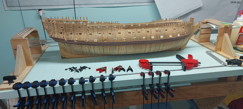
The main wale jig-saw pieces are installed on the stbd side. I've one piece to add to the port side and then some sanding. I think I've done an acceptable job of it for my very first ever (and likely last) time. I found it very difficult, in fact impossible, to make the one side perfectly identical to the other. Human error. The saving grace is you cannot look at both sides at the same time... except from the bow and stern, in which case they seem to match fairly well. I did receive one personal message regarding the my bow: "The sheer should flatten out under the hawse holes as it heads to the bow rabbet." I've looked into it quickly and found my measurements and layout for the underside of the main wale is correct. The width (up/down) expanded a wee bit in cutting out and shaping, and the top side was initially wet and pinched when clamped. The top sides on port and starboard match. I need to go into it in more depth after I get the stern completed. Some adjustments are in order. I am certain there is accumulative error involved in the top side of the wales and the underside of the hawse holes. Some slight of hand may be in order.
-
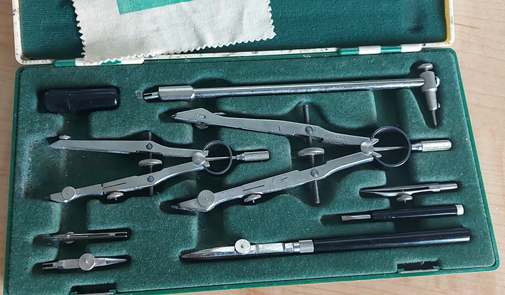
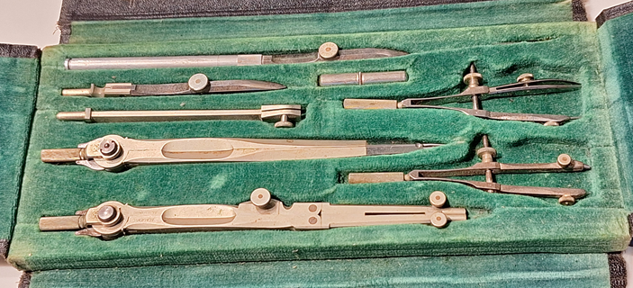
my newer old one is ALPHA Precision (Germany) the older old one is TESCO (Technical Supply Co., Montreal).
-
You can see in the two photos below that to draw straight line the set has a straight handle for one nib. This nib threads onto the handle making it pen like. The other nib options have slots to fit and clamp onto the compasses. The newer set is mine, about 60 years old now. The older set was my grandfather's, circa 1900.
-
This YouTube video shows the pen in use. https://www.youtube.com/watch?v=W3XlJWzvSVM see from 2mins 30 sec to 3 minutes If comfortable loading and using an draftsman's ink bow pen then there is on problem. I suppose this might be easier for some.
-
Getting near the end of installing the main wales. I'll be away from the shop for a few days. When I get back I'll install the last 2 sets and then work on planking the lower transom and sanding the wales to the planking.
-
Looks like a nice spot with easy access. Myself, being situated between two of the of the great lakes (Erie and Ontario), I must regularly remind myself that not all "lakes" are massive. I am think of the phrase from the famous Crocodile Dundee movie: "That's not a knife. This is a knife!"
- 71 replies
-
- 2
-

-

-
- Miss Adventure
- Model Shipways
- (and 2 more)
-
it all came together nicely! does the pond/lake have a name? It is good to be able to walk around and retrieve a boat when things go wrong and she drifts to the other side. ask me how I know.
-
Golden Hind by Rock_From_Korea - 1:48
AON replied to Rock_From_Korea's topic in - Build logs for subjects built 1501 - 1750
some images seem to be missing 1980 and 1985 -
There is an easy way????? 🤔
-
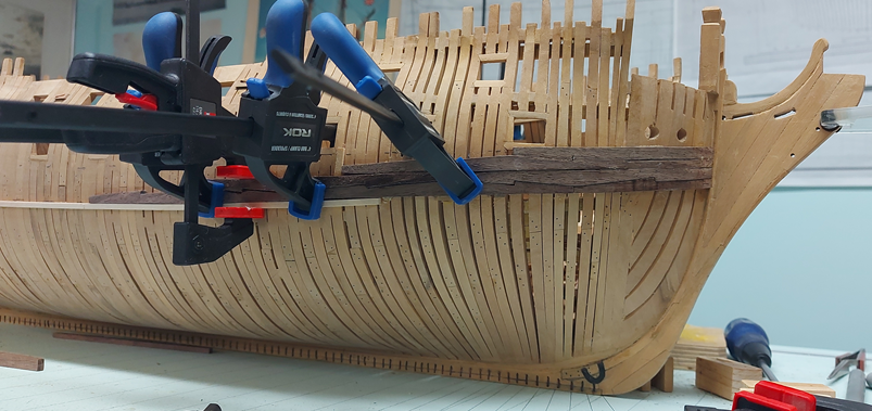
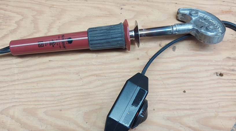
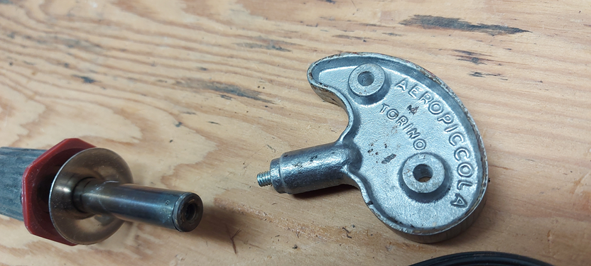
Getting back into it and it is slow going right now. Soaking the pairs in boiling water then clamp them to the frames, one on each side of the ship (port and starboard). Once dry they come off and the soldering iron gets used to remove the spring back. Then they get glued and clamped in place. I am about to lay the wale planks over the flat area, no bending, so that should go quicker. I managed to get the gifted Areopiccola bending head adapted to my soldering iron. I cut off the two tabs, filed and sanded it flat and no sharp edges. Drilled with a #29 bit and tapped 8-32 thread, then inserted a screw, cut off the head and filed that edge. Then just screwed them together. (Thank you Mort!)