


jbshan
-
Posts
1,222 -
Joined
-
Last visited
Content Type
Profiles
Forums
Gallery
Events
Everything posted by jbshan
-
And apparently the Brown's yard and Bergh's were adjacent to each other, about where the New York Navy Yard would be established in later years. Maybe that was zoning or maybe that was just a good place to have a building slip. Yes, a small world, and you keep running into the same individuals, or maybe I should say the usual suspects.
-
 ditto. You get a sense of the multitudes involved, which shows up in the monotony for each item.
- 843 replies
-
- 3
-

-
- niagara
- model shipways
- (and 2 more)
-
In re putting ports in a merchant vessel: They almost all had ports as merchant vessels, it may have been a simple matter of enlarging those a bit or adding a couple more. They wouldn't have been terribly large, probably at most 9 pdrs. Lexington had 6 pdrs., although 'reinforced' so a bit thicker metal in the barrel, which would have allowed a greater charge, but because of the heavier barrel, not much if any more recoil. They could be rigged low down to the ship's side so the eye and ring bolts could get into solid structure. The biggest difference between warship and merchant is the shape of the hull, tubby in most merchant ships, less so in warships, they usually sailed faster, and the warship had heavier framing, this second not showing much on the exterior.
-
Lou, the lines of Davis' model are taken from those for the British brig, of about 1800. Lexington was built somewhat before 1775 as she was an existing merchant vessel bought in to serve in the Continental Navy. The two types of vessels would not much resemble each other as the standards and practices of design had moved on a fair amount in the intervening 25 years. (Conversation with Clay Feldman, 2 of Davis' grandsons and Art Herrick, a noted researcher, at the 2004 NGR conference in Portland Maine.) If you have a copy of Brig Irene an example of one of those Cruzer class vessels that had a long life after the wars with the Netherlands Navy, the model being at one of their museums, you can compare. There is also the pair, Cruzer class brig sloops and Snake class ship sloops, which use the same hull design. All these correspond with Davis' Lexington.
-
Goodness, you guys have been wearing your fingertips to the bone typing all this. For the moment, I'll address the Lexington questions, and try to come up with something on the rest a bit later. After more coffee. Davis' Lexington model seems to have begun life as his version of the well-known British Cruzer class brigs. During the depression, when shipbuilding and design jobs were scarce, he wrote up this model, publishing a guide to its building, but changing the name to Lexington, perhaps in an effort to appeal to an American readership. The model I built (am building. I work intermittently and slowly) is the Clay Feldman/dlumberyard semi-kit version which was featured in Seaways' Ships in Scale. This model is based on a contemporary painting of Lexington after her capture by the British. As such, she should more resemble a merchant conversion than the 25 years newer war brig, Cruzer.
-
vossiewolf, yes, yes, and yes. If you go too far away from them, things get crowded, the ship gets topheavy, doesn't sail well, hogs excessively, all sorts of bad things happen. As one example, one of the smaller of the 'first frigates' was armed with 24 pdrs, to make her as powerful as the larger trio. Turned out she sailed better and swam properly when she was re-armed with 18s. Presumably the ports weren't changed, so there would have been larger ports at a larger spacing than the norm. Lou, you've got a little of the opposite problem, trying to fit guns into an existing hull, much as if, as you say, like Lexington she was bought in and armed by the Navy from a merchant vessel. In that case the tables would give guidelines as the guns would have to go in around stuff rather than the other stuff being arranged to suit the guns.
-
Besides thinning a couple of planks if needed, when they got towards the last few, if it looked as if they were going to need a couple of tiny planks, they would use a few wider ones, as they approached the ends, to make things come out even. They were starting with trees, remember, not pre-cut strips.
-
I'm not in immediate possession of the tables, but guns and carronades of each caliber had necessary 'room and space', if you will. The port of a particular gun would be required to be 2 feet 8 inches tall X 3 feet wide and the distance between ports be 10 feet. The size of port opening was obviously to allow for proper aiming and the spacing was to accommodate the size crew needed to operate the gun. This was the second step in design of a warship, the first being that 30 guns of 24 lbs. were required on the gun deck. Plug in the port size and spacing figures, add a percentage for the run and entrance of the hull and you knew how large a ship was required. (Don't hold me to any of those figures, I just made them up.) Within reason, the stays were moved to make room for the guns. Broadside guns would probably not be interfered with by the masts. They only need to recoil about a third the length of the barrel.
-
Perhaps I should add that the white stuffe was used for voyages to warm waters, which I can assure you does not include New England in the winter, and was the most expensive of several alternative coatings.
-
The 'white stuffe' follows the wale on the side and this line is continued across the transom. It obviates the need to determine and mark and mask a waterline. Also, and perhaps more important for the designers, that's how Mayflower II is painted.
-
It just keeps getting, ummm... MORE.
- 2,625 replies
-
- 7
-
-
- kaiser wilhelm der grosse
- passenger steamer
- (and 1 more)
-
Yes, just a few licks with fine sandpaper. I only show the pics that came out of parts of the model that came out.
-
For anybody wanting to shape flags, go out and sit at the mall, Burger King, maybe a factory or other commercial concern, wherever there's a flag of the size you want to model. Remember these things were huge. The largest ensign for Constitution would have been about the size of the Star Spangled Banner at the Smithsonian which is 30 X 42 feet. Watch your chosen subject in the breeze. It may have a basic waviness with small ripples running over the surface as you sometimes see in old van de Veld paintings. In any event, watch it for a while, take a few pics, try to 'get into' the movement. There should be a general radialness to it from the upper corner where the halliard is. Then use Chuck's paint brush handles.
- 1,048 replies
-
- 7
-
-
- syren ship model
- cheerful
- (and 1 more)
-
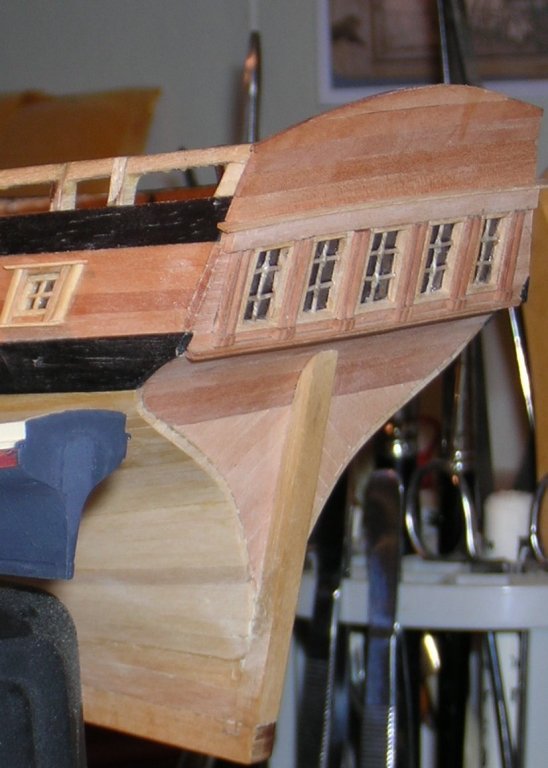
The pic doesn't show much of the nice diag. plank. If you wanted to point them up a bit, knock off the corners with a couple of licks with sandpaper, then they would show better with paint. Here's my Lexington which will not be painted. And my model of a 12 pdr. broadside gun where I've knocked off the corners of the plank to accentuate them under the paint.

-
in re stern ports: Description p 19, photo p 25. I can't imagine they would have seen much if any use and were probably nailed and caulked shut. They could have been used for guns or for loading long items such as timbers for spars. I took a quick stroll through the destructions, didn't find it, but I would think it might help to pin a temp sternpost as a guide while you plank the lower part. How'd Willis (careful, I have a cousin Willis) do the color? Mirrors, purely smoke and mirrors.
-
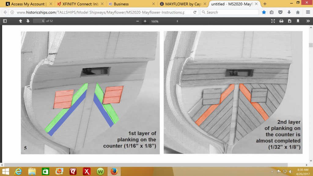
Your wife is probably pretty smart. Get that one in the corner where the sternpost meets the transom first, left right side, red. Or, what might be easier, on the left, do red first, the port lids, then the one below the corner plank, blue, then the corner plank, green. RBG It might help to draw it all out first on the bulkhead.
-
The 'trench' at the bow: as long as the shape is fair, in other words the plank lies smoothly against the blocking, indeed the bulkhead may have been taken too far and you should be OK, just, as you say, you have a fatter curve than another builder might have done. You should be gluing the plank edges to each other. It makes the several planks into basically a panel so they support each other. If you didn't already solve the problem, I would suggest you shape that last plank to the curve, which will make it fairly thin in the middle, then insert another plank above it to meet the parallel plank coming down the transom. It will be almost impossible to bend that one, so cut it to shape. When you do the second layer, you can perhaps cut two or three planks to shallower versions of the curve and approach it gradually.
-
The square stern makes it less likely you will need any blocking, but check things out there before you get a bunch of plank on. If there's a really big gap between bulkheads and/or transoms, you might consider some. I just looked at the photos in the destructions and it looks well-supported there.
-
As I read the instructions, the topsides were double planked and the underwater body single planked. The second layer was beveled down to meet the thickness of the first layer at the wale, which, when added on top concealed the meeting place. It also shows quite short plank lengths in the second layer, pp 17, 18.
-
Errrmm... What I was thinking of was from 'E' forward to the stem. The plank will have to have almost a ball-like form there and the tendency to edge set may cause a 'wrinkle' in the plank which may well differ in location from plank to plank and look really weird. Blocking behind there will at least tell you when one edge of a plank is lifting. Is there anything in your instructions helping with the theory or concept of planking?
-
No, I think you have the right of it. But this is a first layer of plank, yes? The second layer will develop a true rabbet or a simulation of one. You still need to cut your plank pretty precisely, if nothing else, for a good fit and maximum gluing surface.
-
Cap, you may well want to do the same thing with the portion forward of that as well. It'll help the planks keep aligned with each other with less chance of 'wrinkles'.
-
Gentlemen, I think you will find that, going into the rabbet, the plank will need a 'point' with the longer side to the inside. This can help keep the hood ends snugly into the rabbet, but things need still to fit properly. I would suggest not trying to go full length with the planks, but keep them to the region of 20 feet or so, to fit the spacing of the bulkheads. You will need to have the width changing, wider in the middle of the hull and narrower at the ends, and it is easier to do this with shorter planks. Also, when you reach that point, if you have to fit a plank into both a stem and sternpost rabbet, working from the ends toward the middle is about the only way to go. There are some threads on this forum covering the process. Just use the search feature. Perhaps again OBE.
-
I keep my small change in my parse. Queen Charlotte, if I have my time line right, was built in partial response to the US building of Oneida, which was a pure warship. Oneida was, yes, on Lake Ontario, but the British boosted things to a higher level on Lake Erie as well. The Provincial Marine was a quasi-navy service that performed the government's business up and down the lakes, but also was available to carry civilian merchants' goods and personnel when Govt. business didn't fill up the vessel. You should perhaps think of a cross between the mail packet service and the East India Company that was well-armed but with fair cargo capacity and owned and operated by the Govt. Detroit, Lawrence and Niagara were all launched in 1813.
-
Nice camels! Queen Charlotte was built at Amherstburg specifically as a warship, for the Provincial Marine. She was launched in 1810, a 'Corvette Brig to carry sixteen guns'. She was built to a draught of William Bell for a ship rather than as a brig. Robert Malcomson, Warships of the Great Lakes, quoting original documents. She was somewhat smaller than Detroit and the US Brigs, and on the day carried 16 guns on the broadside plus one on a pivot.
