
FreekS
-
Posts
178 -
Joined
-
Last visited
Recent Profile Visitors
1,074 profile views


-
 Wreck1919 reacted to a post in a topic:
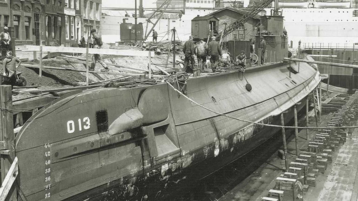
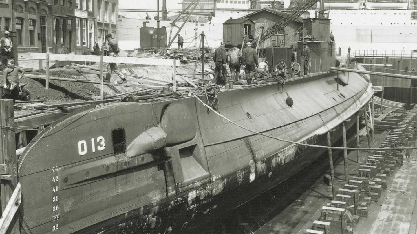
Hr Ms O-13 by FreekS - 1:50 - RADIO - 1931-1940 - Last Dutch Sub “on eternal patrol”
Wreck1919 reacted to a post in a topic:
Hr Ms O-13 by FreekS - 1:50 - RADIO - 1931-1940 - Last Dutch Sub “on eternal patrol”
-
PvG Aussie reacted to a post in a topic:
Hr Ms O-13 by FreekS - 1:50 - RADIO - 1931-1940 - Last Dutch Sub “on eternal patrol”
-
mtaylor reacted to a post in a topic:
Hr Ms O-13 by FreekS - 1:50 - RADIO - 1931-1940 - Last Dutch Sub “on eternal patrol”
-
yvesvidal reacted to a post in a topic:
Hr Ms O-13 by FreekS - 1:50 - RADIO - 1931-1940 - Last Dutch Sub “on eternal patrol”
-
GrandpaPhil reacted to a post in a topic:
Hr Ms O-13 by FreekS - 1:50 - RADIO - 1931-1940 - Last Dutch Sub “on eternal patrol”
-
Canute reacted to a post in a topic:
Hr Ms O-13 by FreekS - 1:50 - RADIO - 1931-1940 - Last Dutch Sub “on eternal patrol”
-
 FreekS reacted to a post in a topic:
Paddle to the Sea by Jason Builder - Solid Wood - 1941
FreekS reacted to a post in a topic:
Paddle to the Sea by Jason Builder - Solid Wood - 1941
-
Rik Thistle reacted to a post in a topic:
Hr Ms O-13 by FreekS - 1:50 - RADIO - 1931-1940 - Last Dutch Sub “on eternal patrol”
-
bridgman reacted to a post in a topic:
Hr Ms O-13 by FreekS - 1:50 - RADIO - 1931-1940 - Last Dutch Sub “on eternal patrol”
-
Jack12477 reacted to a post in a topic:
Hr Ms O-13 by FreekS - 1:50 - RADIO - 1931-1940 - Last Dutch Sub “on eternal patrol”
-
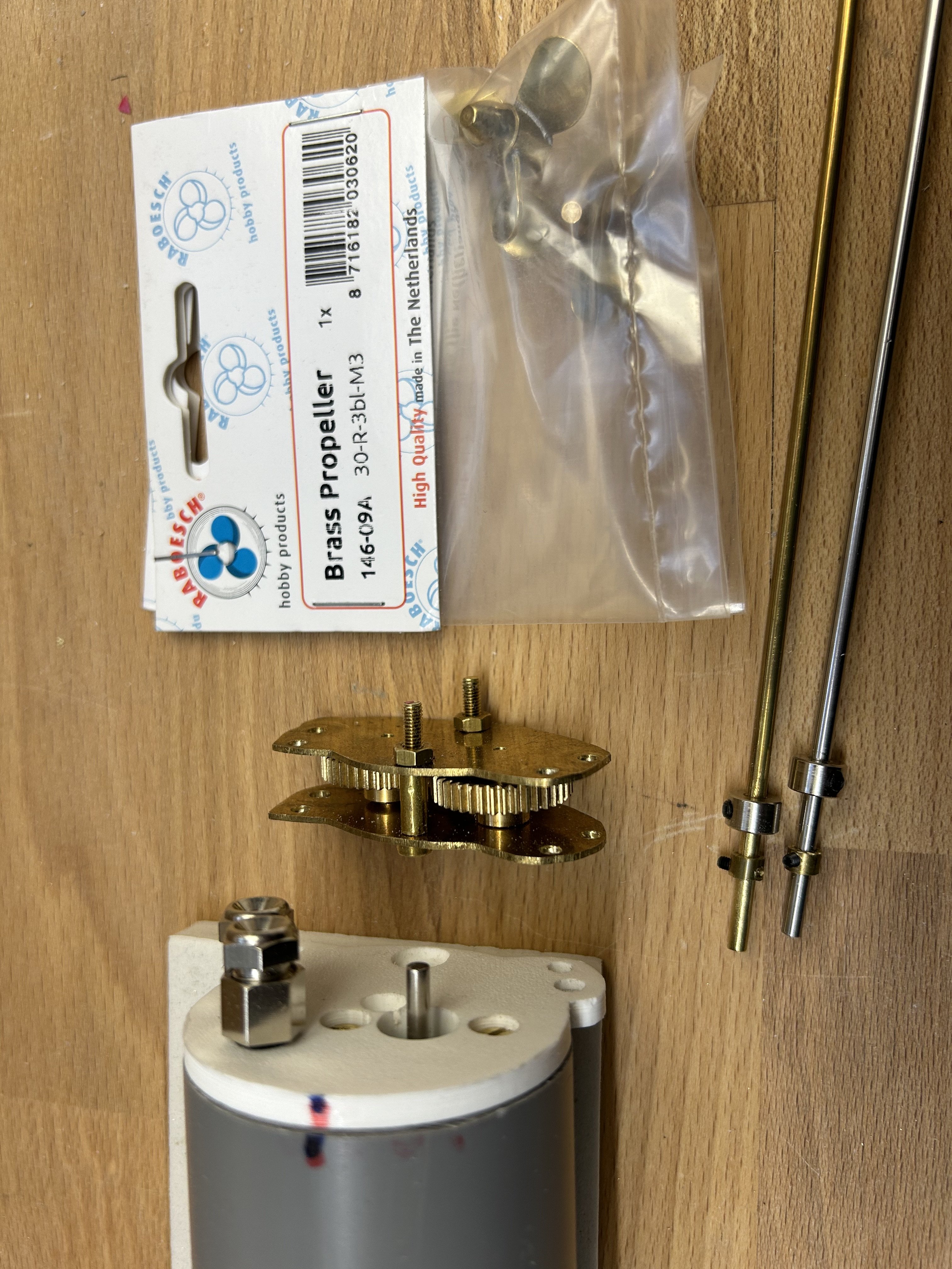
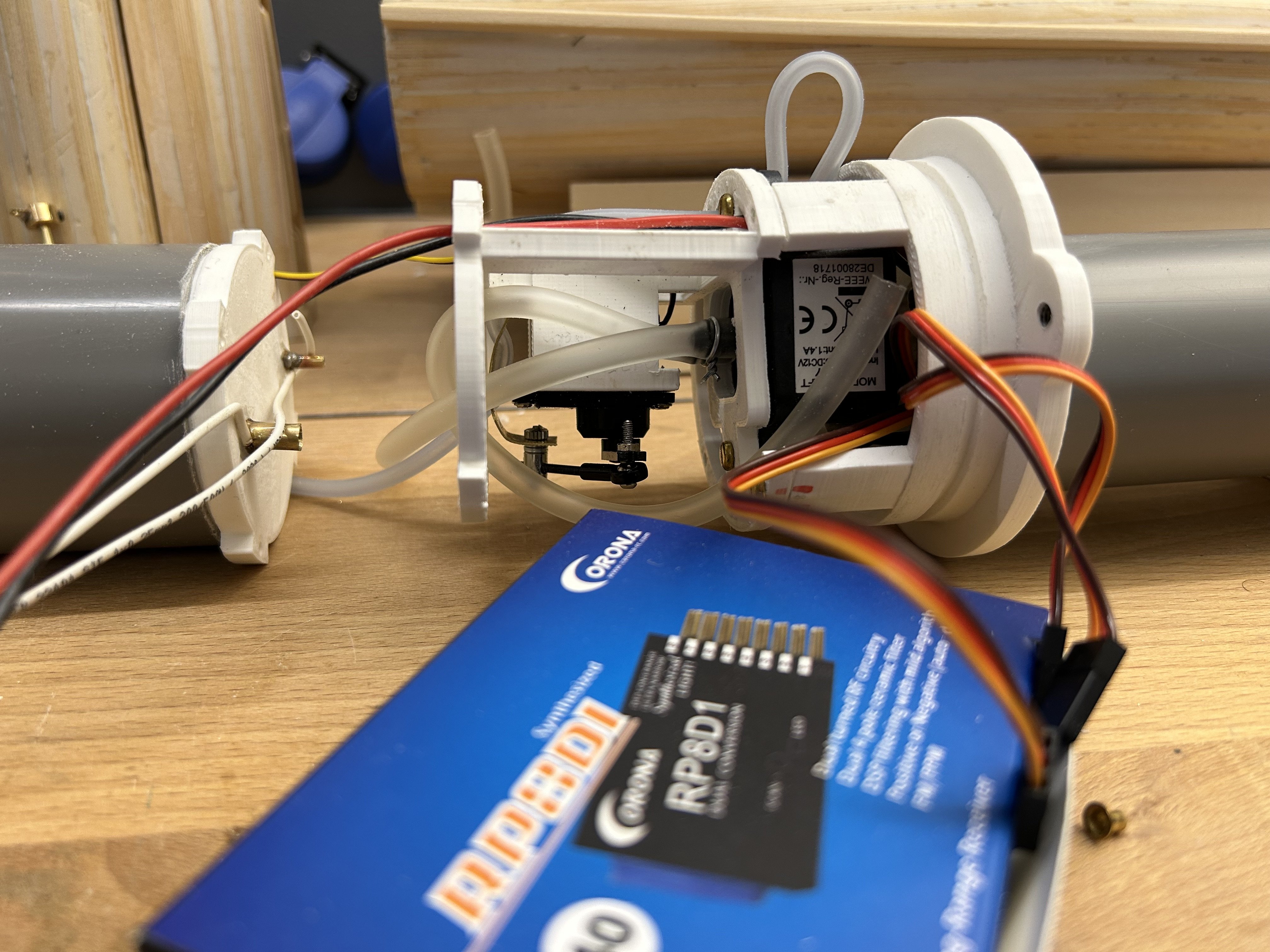
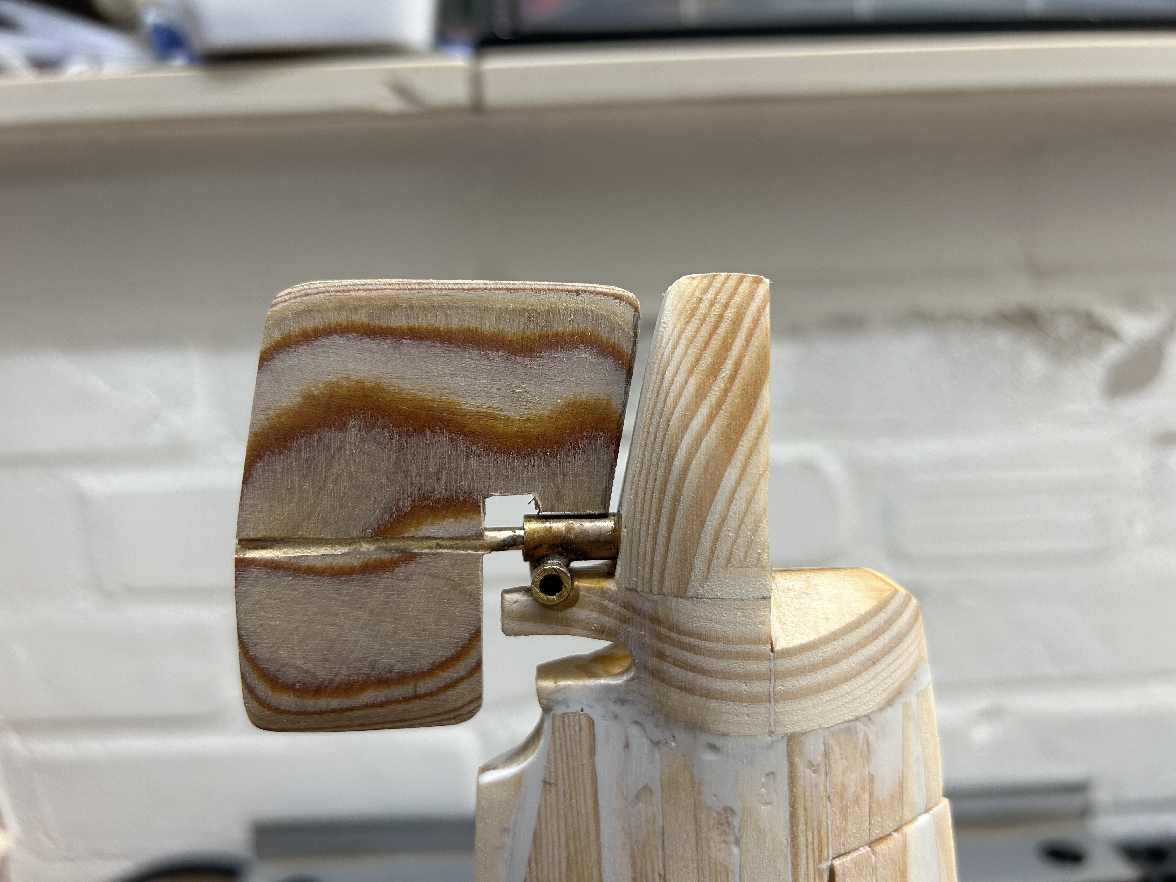
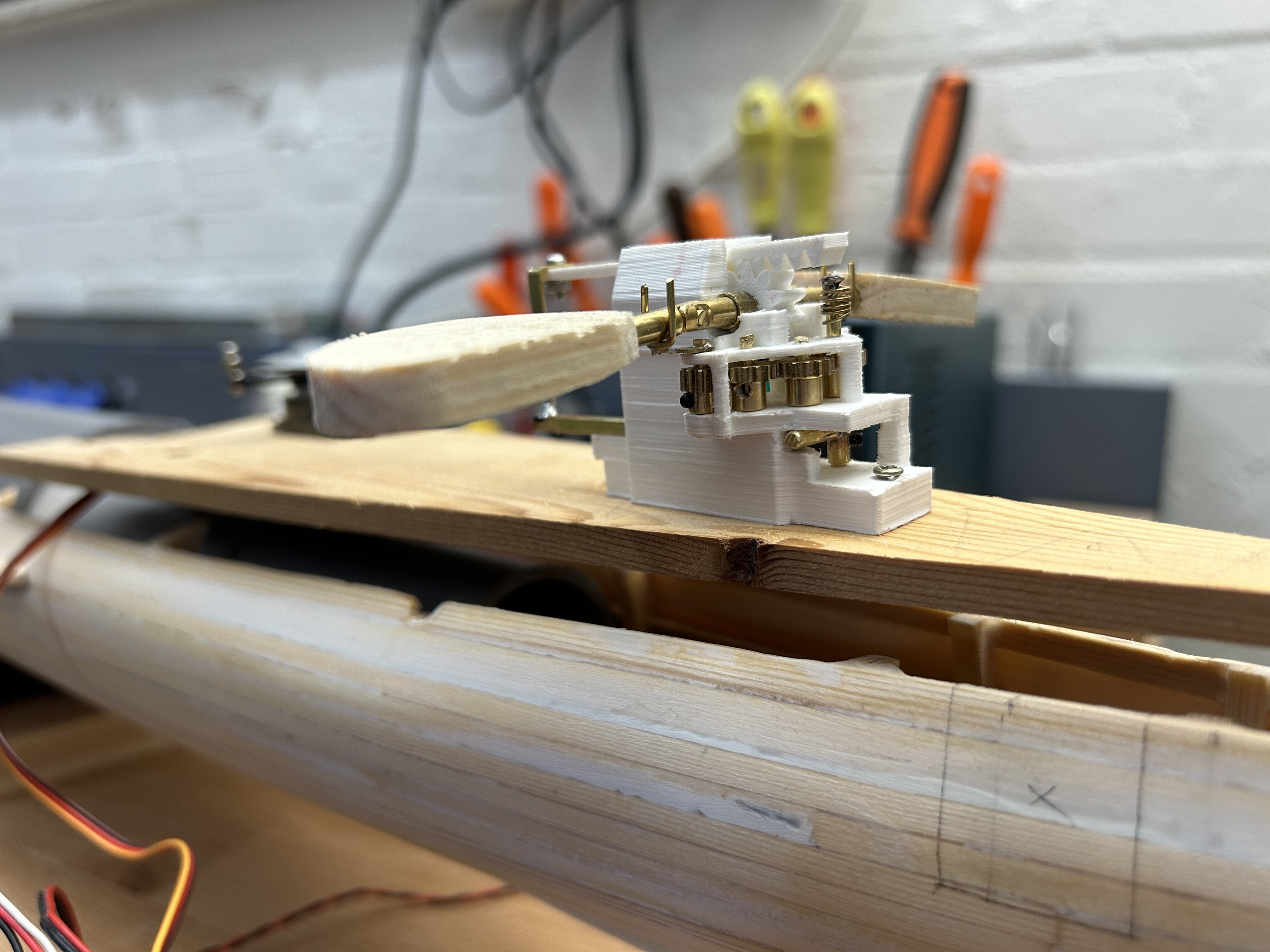
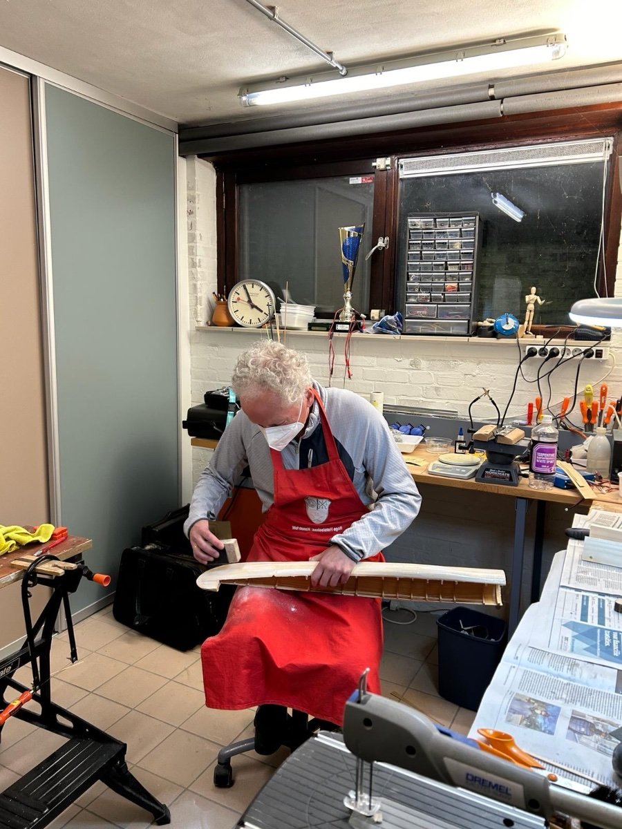
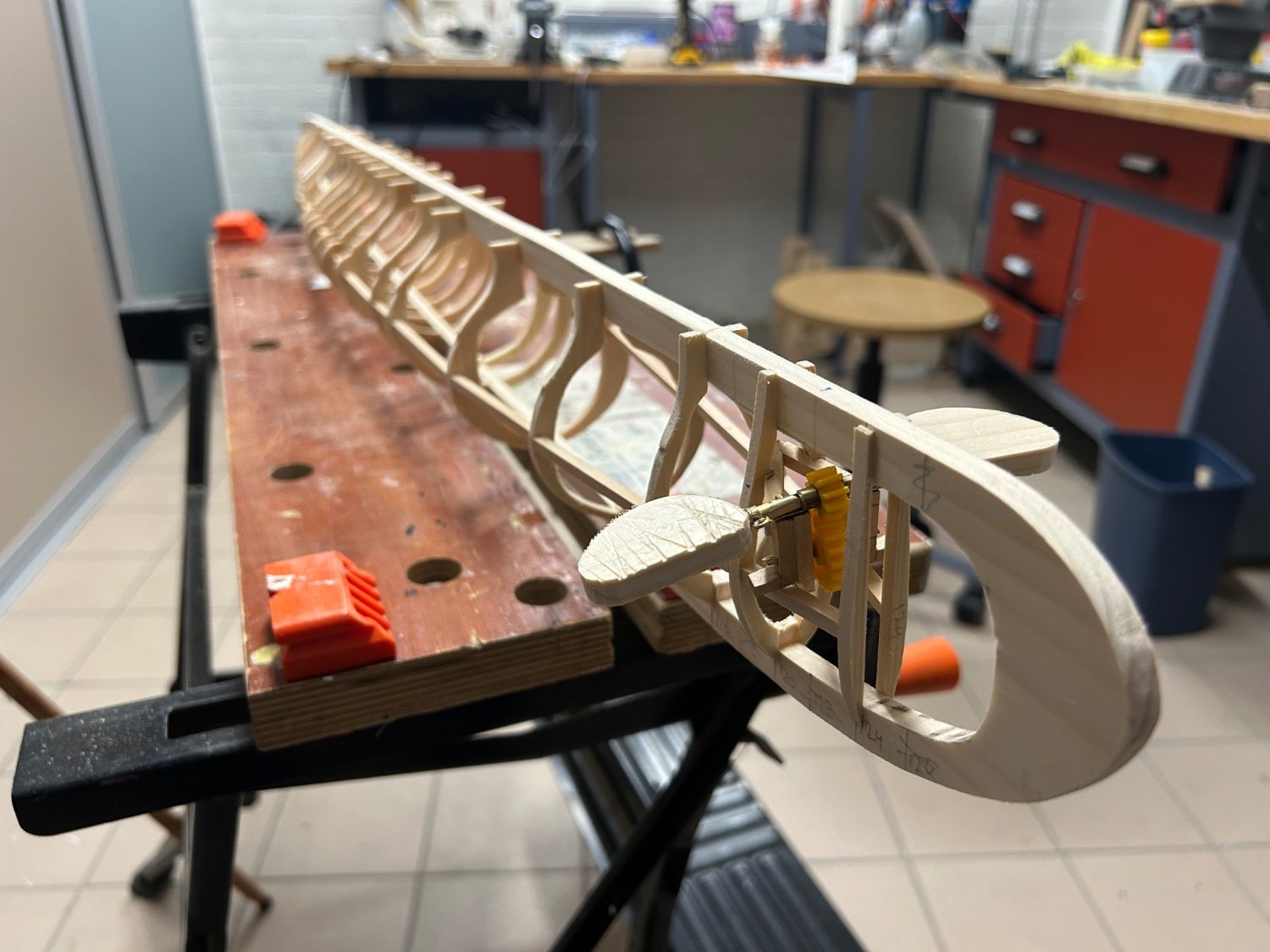
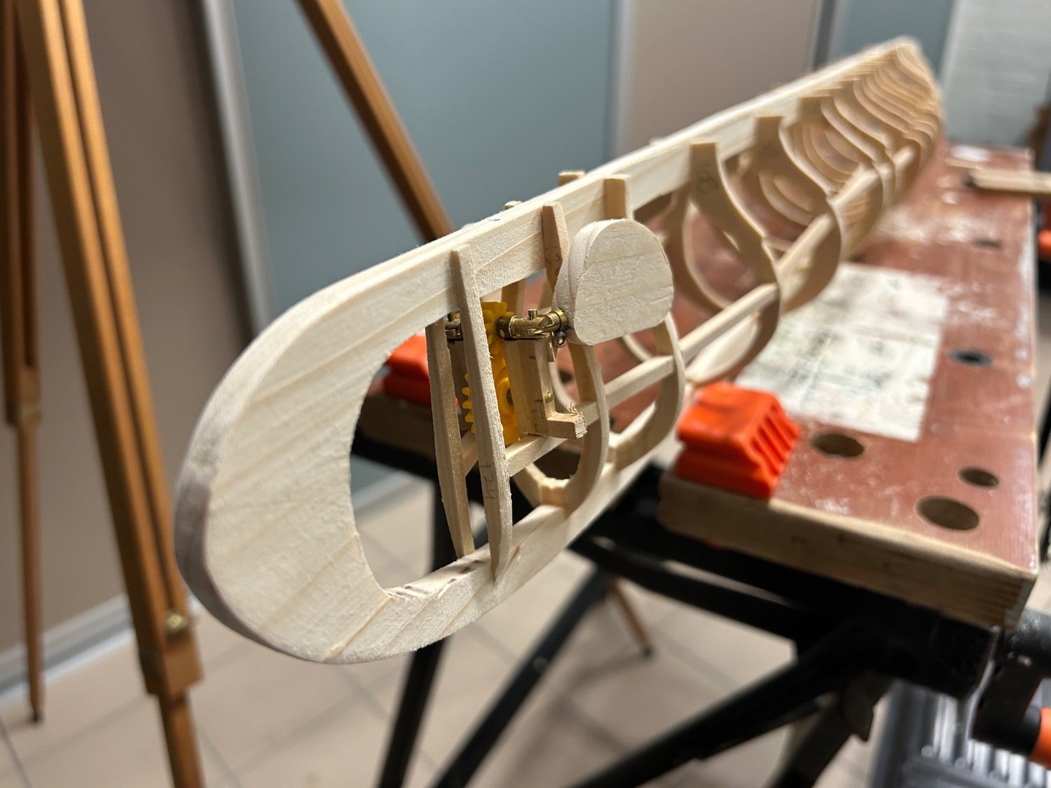
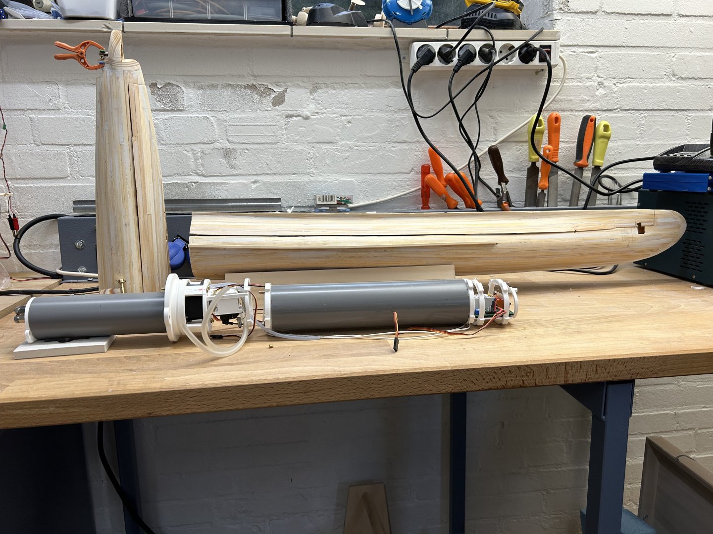
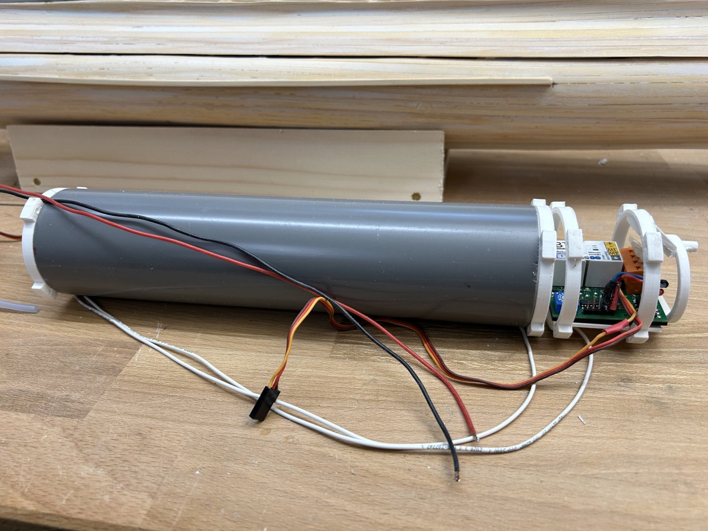
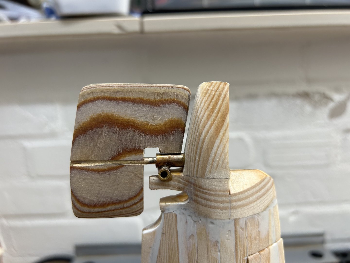
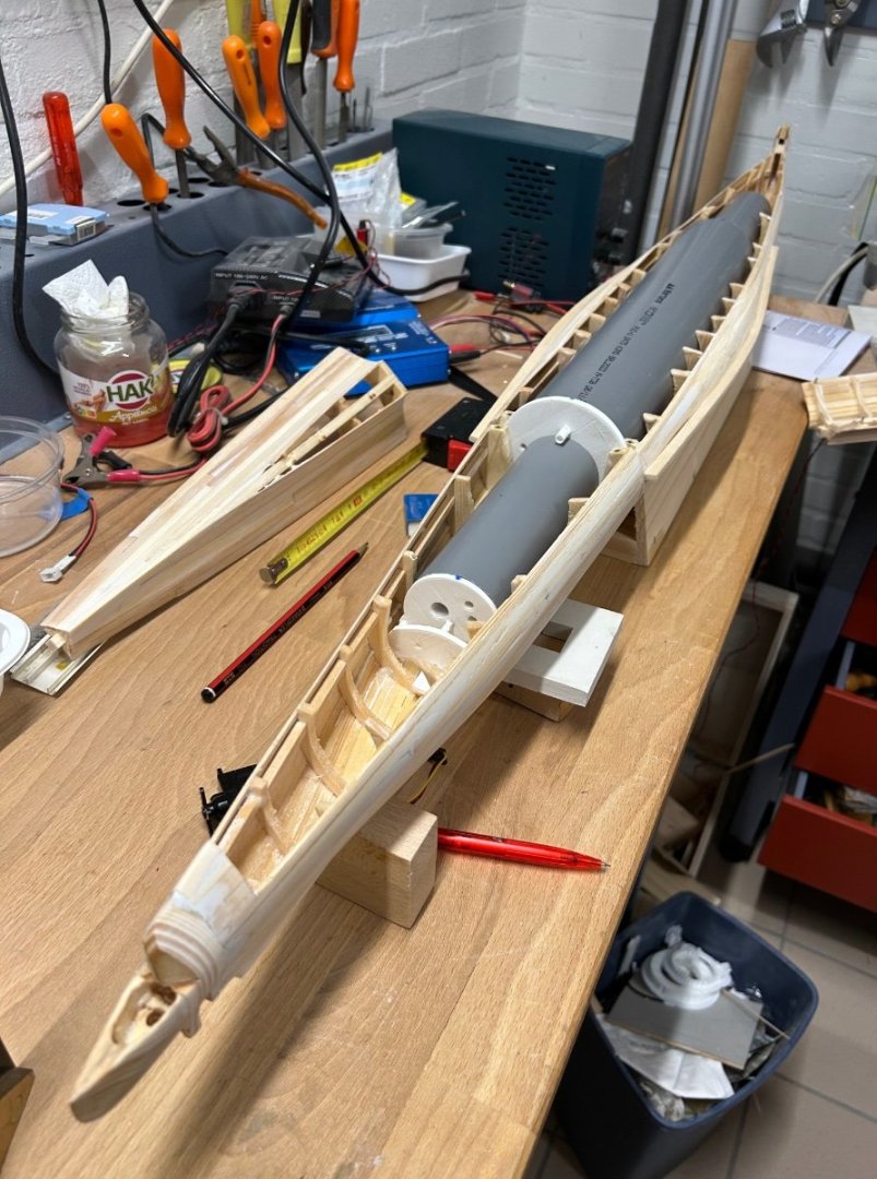
Ok, further with self-taught engineering. Many if not all concepts below are well known in the model sub world, I did not invent them! I want to have a final design of the water-tight compartment (WTC) and its connections to propellers and rudders because only then can I plan and make the required holes in the wooden hull and finish the hull. The WTC will consist of three connected PVC pipes connected with 3D printed parts - aft: 44mm ID with the motor, motor controller, and two servos for the rudders and diveplanes, - middle: a 69mm ID pipe with the dive tank (a 60mm PVC tube), the receiver, the pump, a self-made valve as well as the ballast tank controller. - bow: another 44 mm ID pipe with servo for front dive planes and the batteries. These components will be housed in a techrack which is pulled out of the WTC. I’ve been designing these in Fusion360 and printing them on my 3D printer. The techrack will be mounted on four M3 rods to give it strength. here on the left the aft WTC , connected to a printed bajonet (located on the “cut” in the boat in background), and then to the right the beginnings of the techrack and dive tank The dive tank (here left) has a water-in and air-out brass connection. The resistance between these is measured by the dive tank controller to determine if the tank is full. The pump is a 500ml/min gear pump, and since gear pumps are not closed, I’ve re-purposed a mini-servo to pinch the air-out tube closed so no water leaks in when pump is idle. A 40 MHz 8 channel receiver will be mounted here as well. the rear WTC with motor axle sticking out (through a seal) and two o-ring holders for the pushrods to the planes and rudder. The motor drives a gearbox “in the wet” which drives two shafts and 30mm Raboesch props. The white printed part will be glued to the PVC pipe, but the motor can be unscrewed from the outside so that the rear techrack can be removed for maintenance. The screws must be sealed. here the tank again with its controller forward. Many electrical and signal wires will pass over the tank (which will be inside the 69mm ID WTC). finally, I did manage to do a little woodwork, the main rudder consists of two 0,3 mm brass sheets soldered to the 3mm shaft, and then covered with two layers of 1 mm boxwood on both sides. then sanded in shape. Also the future mount of the diveplanes is visible. sorry for the technical stuff - subs are a technical game, but I will get to the nice part of making the conning tower later!


-
FreekS reacted to a post in a topic:
Paddle to the Sea by Jason Builder - Solid Wood - 1941
-
FreekS reacted to a post in a topic:
Paddle to the Sea by Jason Builder - Solid Wood - 1941
-
FreekS reacted to a post in a topic:
Paddle to the Sea by Jason Builder - Solid Wood - 1941
-
FreekS reacted to a post in a topic:
Paddle to the Sea by Jason Builder - Solid Wood - 1941
-
FreekS reacted to a post in a topic:
Paddle to the Sea by Jason Builder - Solid Wood - 1941
-
mtaylor reacted to a post in a topic:
Hr Ms O-13 by FreekS - 1:50 - RADIO - 1931-1940 - Last Dutch Sub “on eternal patrol”
-
No! A chemist!
-
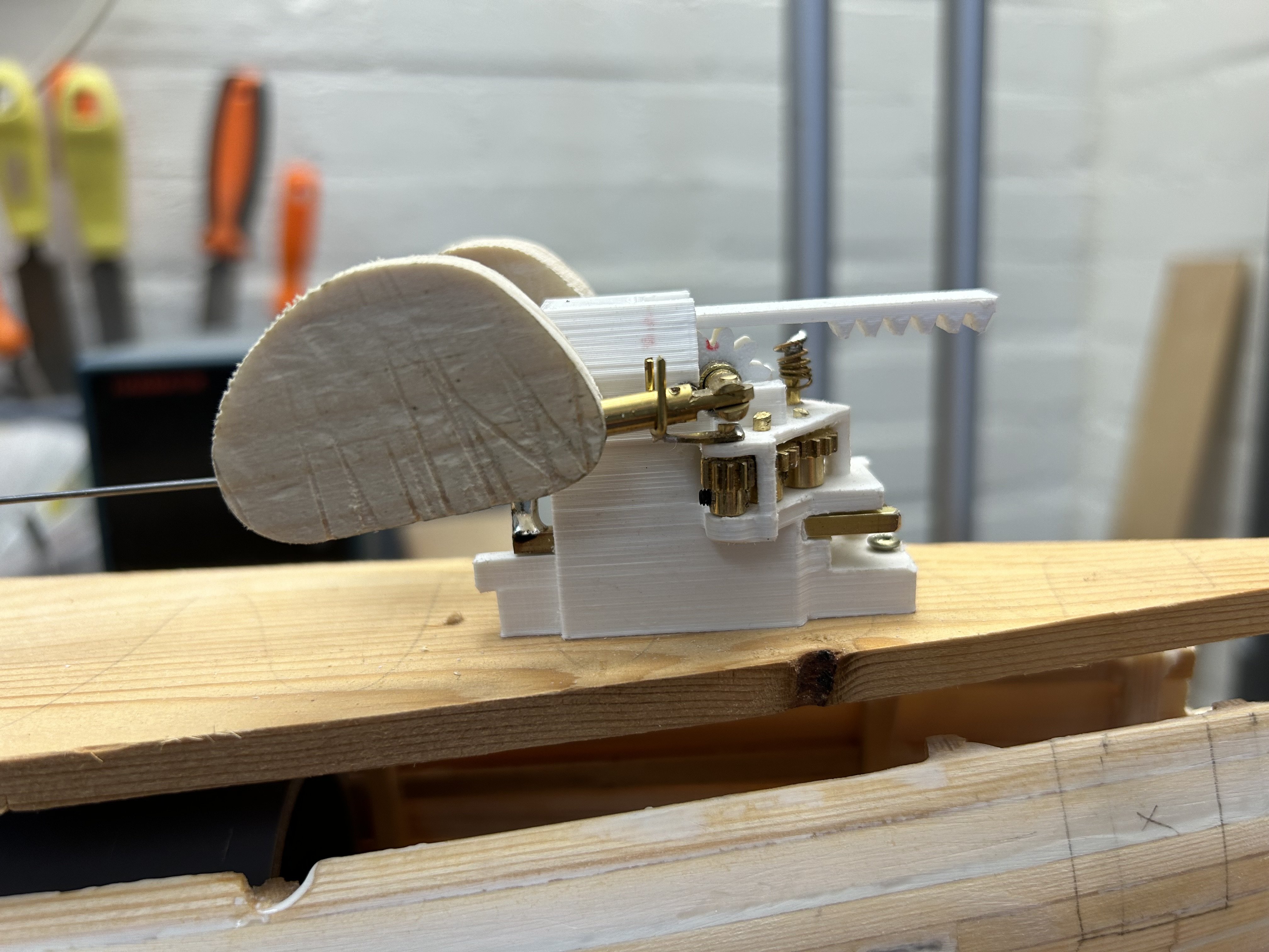
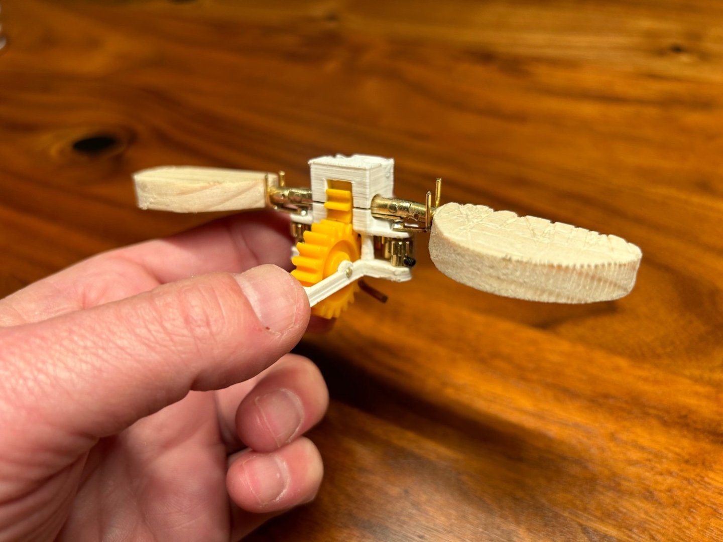
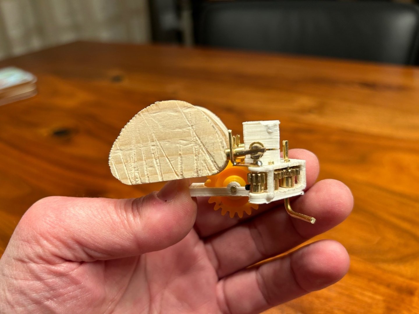
I’ve gone down a bit of a rabbit hole! Having developed the idea of the functioning front diveplanes described above - the ideas for improvement kept coming! I’ve now got a prototype ready to be built into the hull, where the two movements of the front diveplanes, the folding and unfolding of the planes flush against the hull, and the up/down movement of the diveplanes when sailing under water, are achieved with just one servo. the up/down movement is achieved with a white gear and a white linear gear. IMG_0430.mov prior to folding, the planes are rotated vertical by these white 3D printed cogs. On further movement of the servo the linear cog runs out of teeth, and the white gear contain a magnet leaving the planes in the vertical parking position. Then a brass rod pushed in parallel with the white linear gear folds the planes via the brass gears previously described. A spring made from 0,5mm brass unfolds the gears as the servo retracts both rods until the linear gear re-engages. crazy complex, but it runs with little friction, uses less than 0,1 amps on a mini servo and uses no current when not moving. Very happy - will need to program an arduino to tie the servo movement to the “dive” and “surface” commands and the diveplanes signals from the transmitter. now hopefully back to some woodwork, apologies for the distraction!


-
FreekS reacted to a post in a topic:
SMS Karlsruhe by Wreck1919 - 1/100
-
FreekS reacted to a post in a topic:
SS Blagoev (ex Songa )1921 by Valery V - scale 1:100 - Soviet Union
-
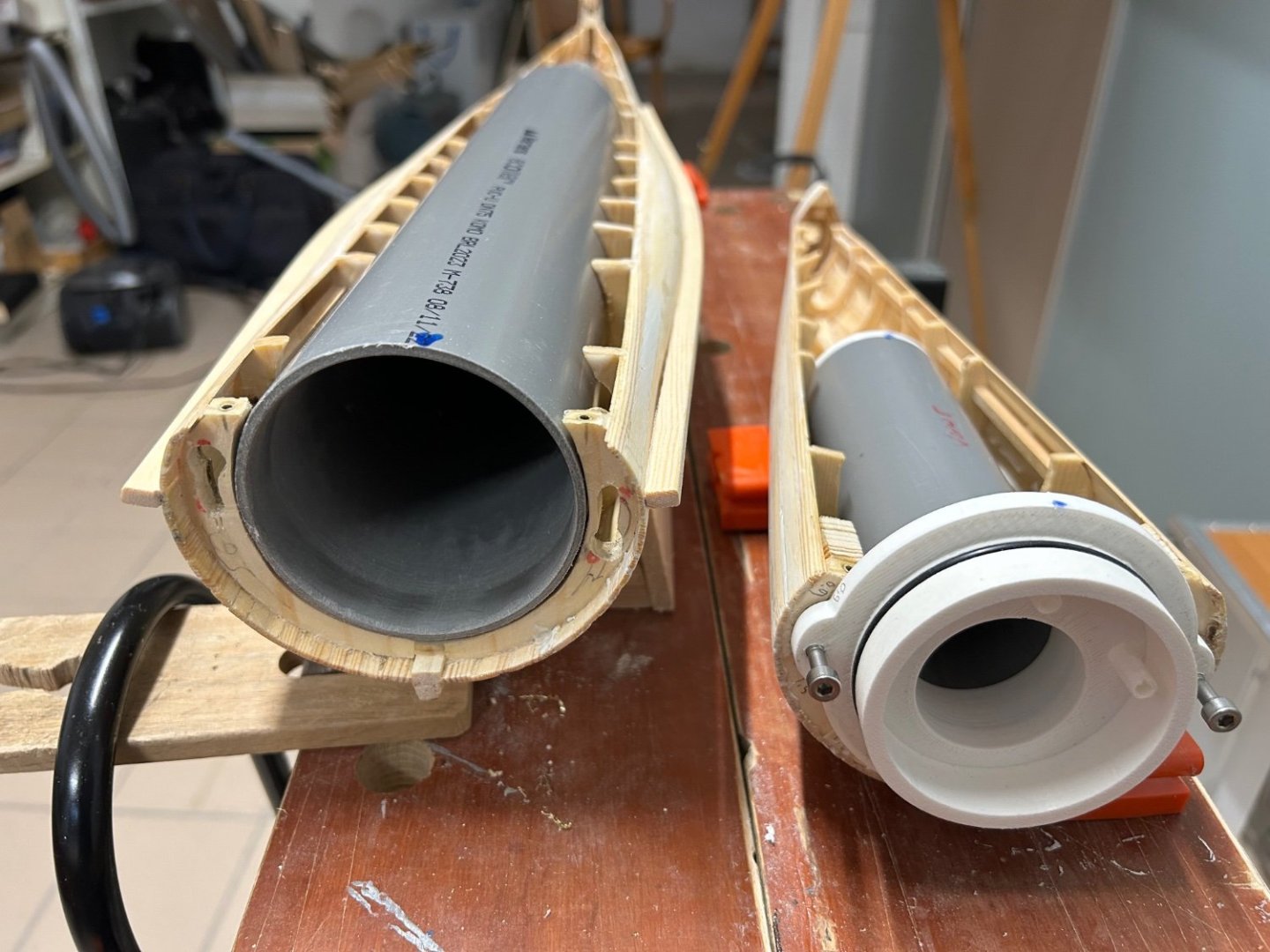
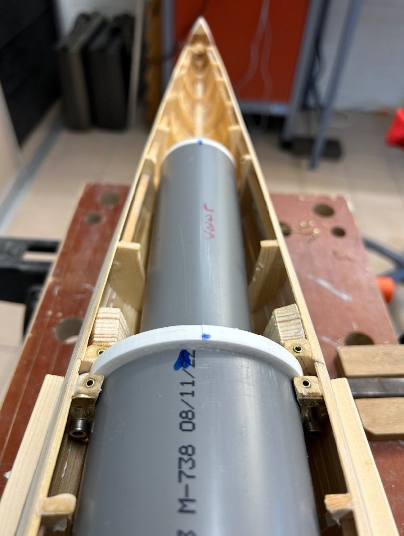
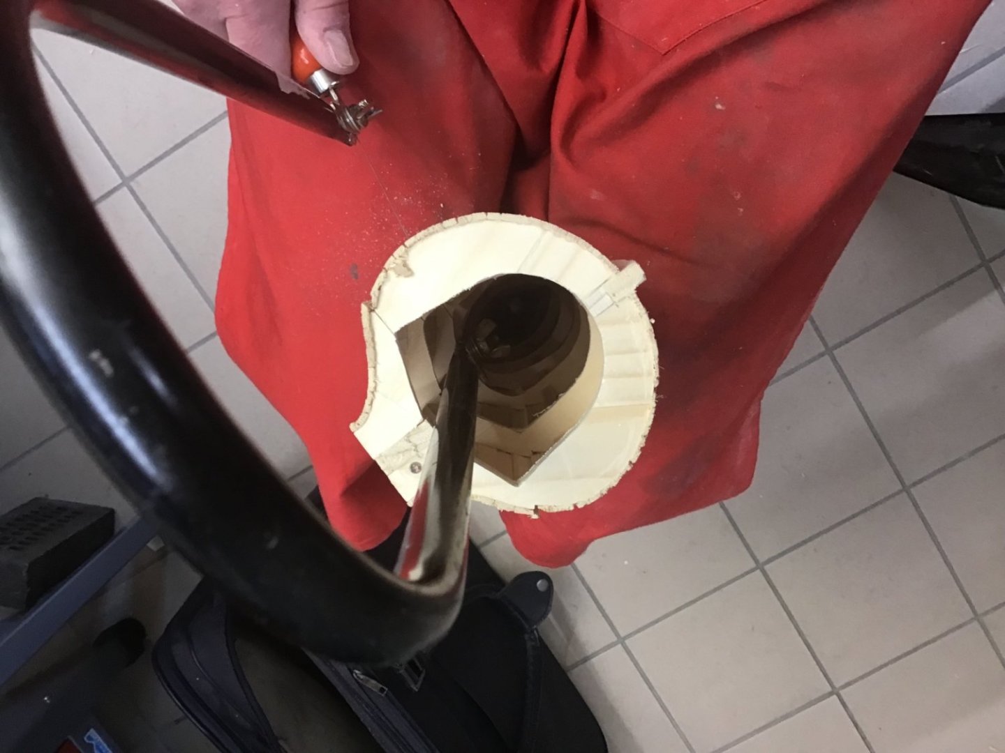
Started work on the water-tight compartment inside the wooden hull. The hull will flood when dived, and the WTC will contain the motors, batteries, receiver, two-way pump and a 500ml divetank to dive the boat. The insides of the WTC can be accessed by a bayonet between the aft 50mm diameter PVC tube and the mid 75mm PVC tube. this is the WTC seen from the stern. The white stern endcap will have two shafts driven by a motor inside the 50mm PVC tube. The holes are where the prop shaft and the rudder and diveplanes seals will come. Between the two white parts of the endcap will come a gearbox to counter rotate the two shafts. Further forward is the bajonet, seen below when opened. two M4 bolts on the start section fit into the keyholes (strengthened with brass) in the front section and thus the two boat halves can be twisted shut. The bajonet contains O-rings to seal the 50 and 75mm PVC tubes. this picture shows the bajonet shut and the bolts holding the two halves together. And finally with the two deck sections attached. now that I know exactly where the WTC and its connections will come, I can start to work on the prop shafts and their outholders, the rudder and diveplanes and the holes in the wooden hull to flood the boat and enable air to escape.
-
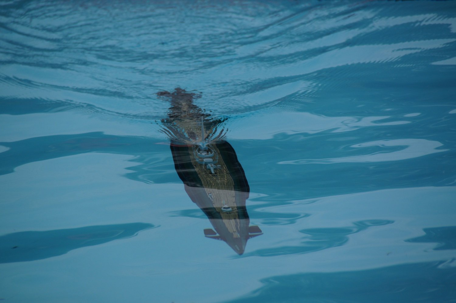
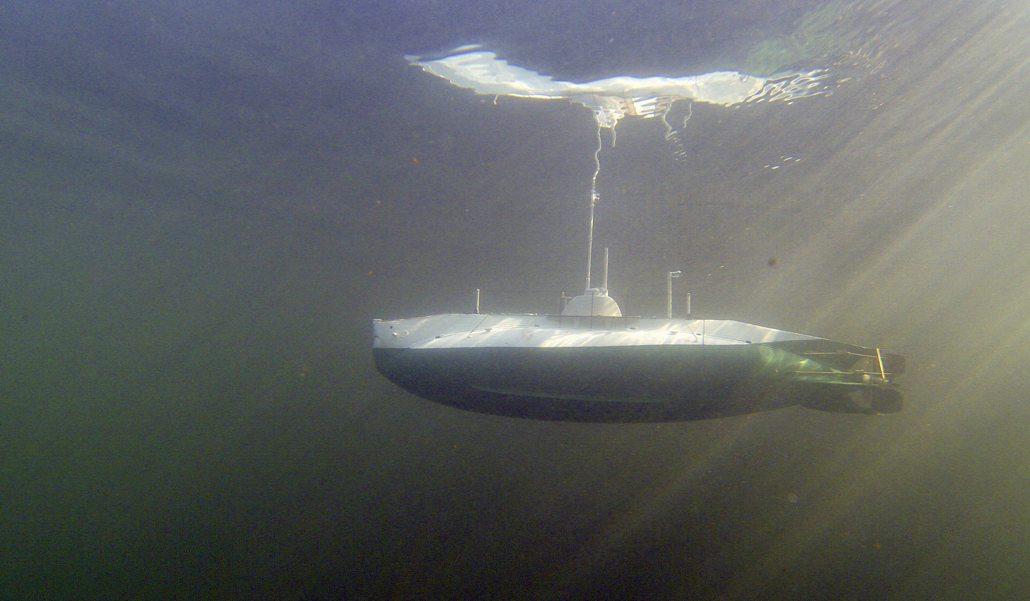
You mean “surfacing after a dive” ! it will be a while….. for O-13, but here is one from my also wooden K-XVIII

-
The four parts of the hull have been sanded and I applied first layer of epoxy filler. The basic shape is now done. I want to get the various holes cut in the hull (for flooding, allowing air to escape, and the rudder, planes and prop holes before I epoxy again - so that all wood becomes sealed. thus I have to plan all “holes” and one of the difficult ones is for the front dive planes at the bow. These planes fold flush against the hull, and are covered by some plating outside the hull. so I started designing the functionality with the allowed space (tiny). This is the result: https://youtu.be/hi7XH0Wy4v0?feature=shared the two yellow gears rotate the common axle of the diveplanes. The axle has a hingepoint to fold each plane. Underneath each hingepoint is a brass gear that turns a pair of messing wires to apply sideways force on the axis outside of the hinges. This turns the diveplanes flush with the hull and back. The two brass gears are coupled through 4 more to work in tandem (could have worked with 2 but they would have had to be bigger and cause conflicts). The large yellow cog and one of the 6 brass cogs will be driven by a servo 4-8 inches further back in the water tight compartment of the boat (this gear assembly will be “in the wet”). This took me a good few hours of brasswork (of which I learnt a lot) and 3D design and printing (at which I’m also a beginner). I’d like to replace the printed parts with messing but I’m not at all sure I would achieve the precision on the boreholes to make it turn properly. I anyhow need to make another version of this as there is some play in the yellow cogs.
-
FreekS reacted to a post in a topic:
Type 45 Destroyer by mikegr - 1/700
-
FreekS reacted to a post in a topic:
Type 45 Destroyer by mikegr - 1/700
-
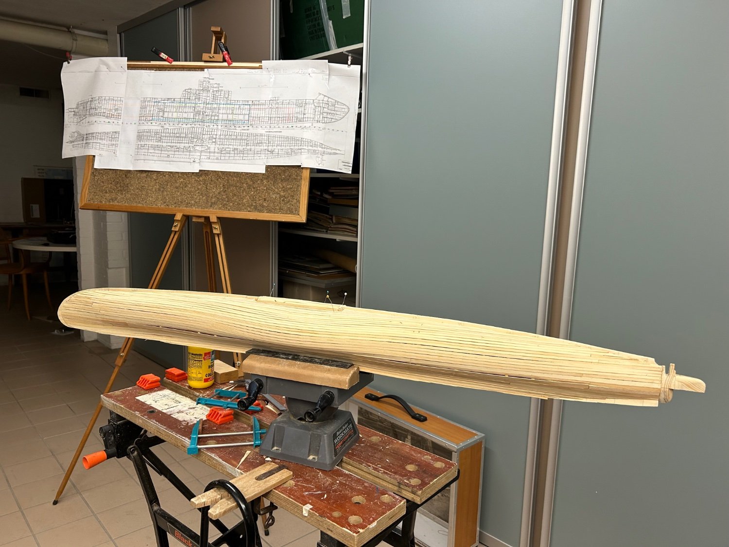
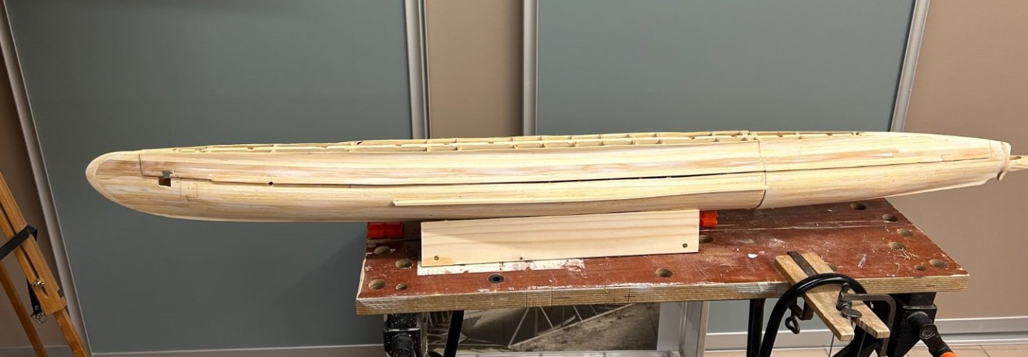
The four pieces came out OK, I coated each one inside and outside with epoxy sealer - mainly to glue all planks together and stabilise the boat against small chips during sanding. There were a few small places with damage from the saw, and I replaced two small pieces of plank. Yesterday applied first layer of epoxy putty and stated sanding that back. The boat parts now feel really strong and I can focus on getting the outside shape smoothed.

-
I winced too! in scratchbuild, I find there is a need to plan in your head these kind of difficult procedures, which I’ve been thinking about for weeks (when to do it, what needs to go first….). Then when you do it, you can move on and think about next steps more clearly - in my case: “ok I’ve separated the hull sections, what’s the best way to fix them together so they come apart easy again”. In my case - the plan is pretty fluid.
-
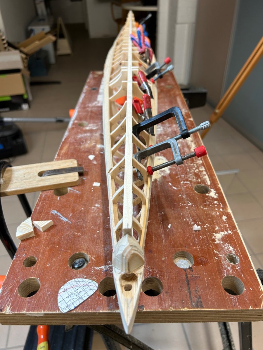
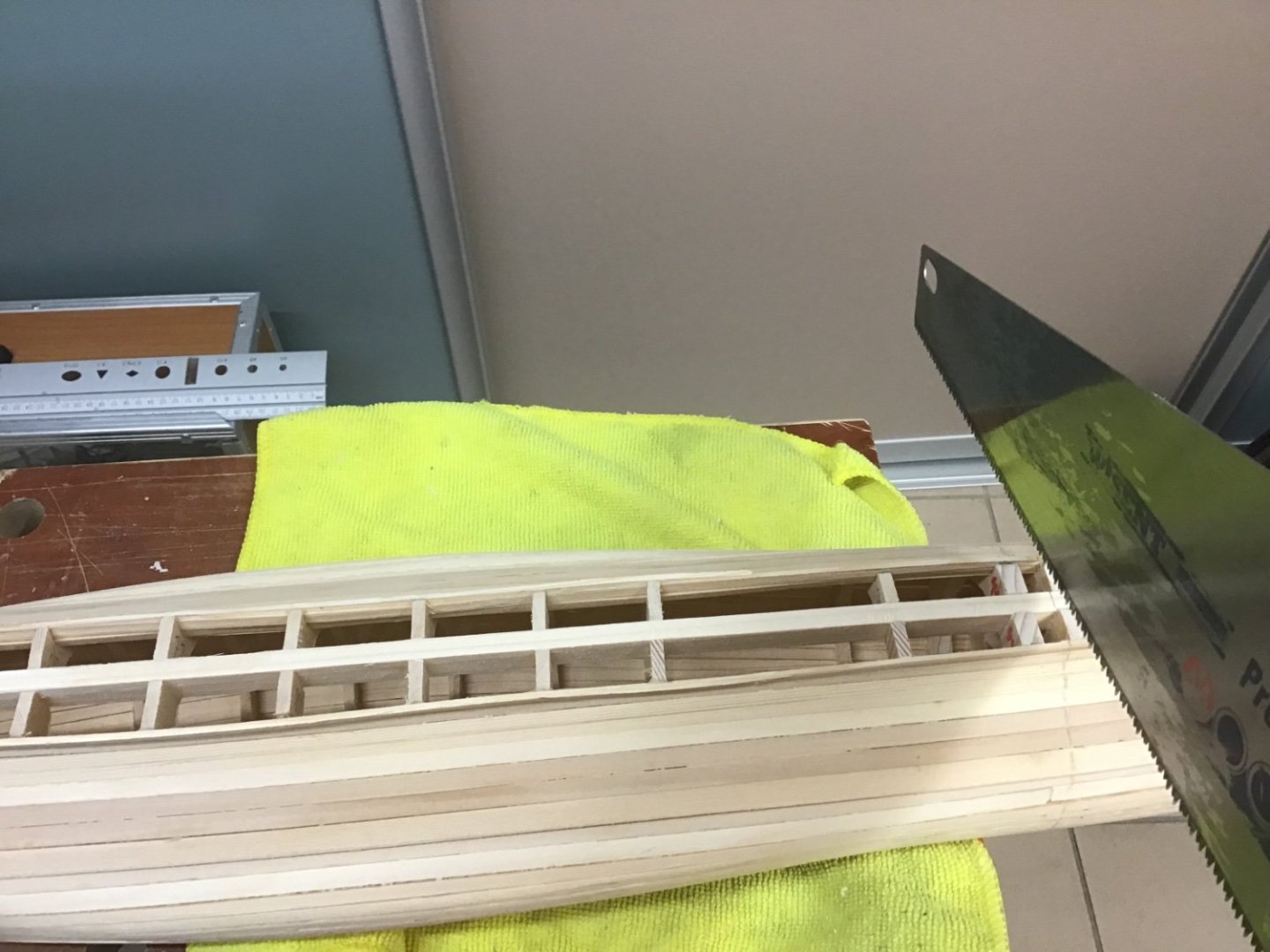
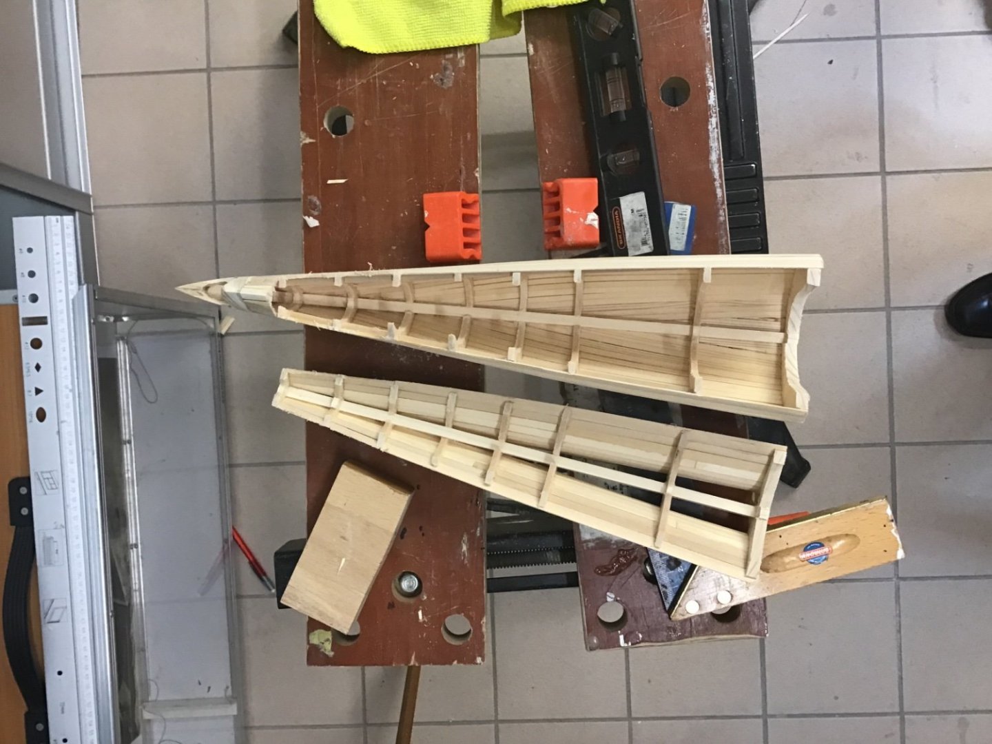
Yes, it’s really taken shape! thanks for the compliments. now comes the best/worst job in building a wooden radio controlled submarine: after some playing with a level, a 90 degree angle I managed to draw the cut lines on the hull. A little splintering, but anything wood can be repaired, and I’m still before the big epoxy putty jobs. This vertical cut is between frames 43 and 44, both of which I made thicker than the other frames. This is where the bajonet closure will be installed later that will give quick access to the boats technology at the water front. to actually build and be able to repair the boat, I’m also doing a horizontal cut that will be closed except for maintenance (with real subs if they need to change an engine they actually cut through the hull). This is where the prop shafts and rudder controls will be built. I’ve done the aft part with a simple jigsaw.

-
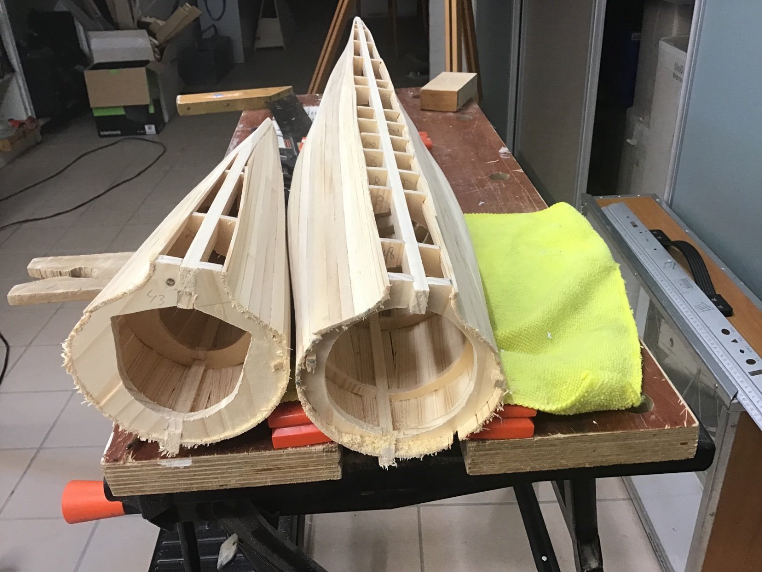
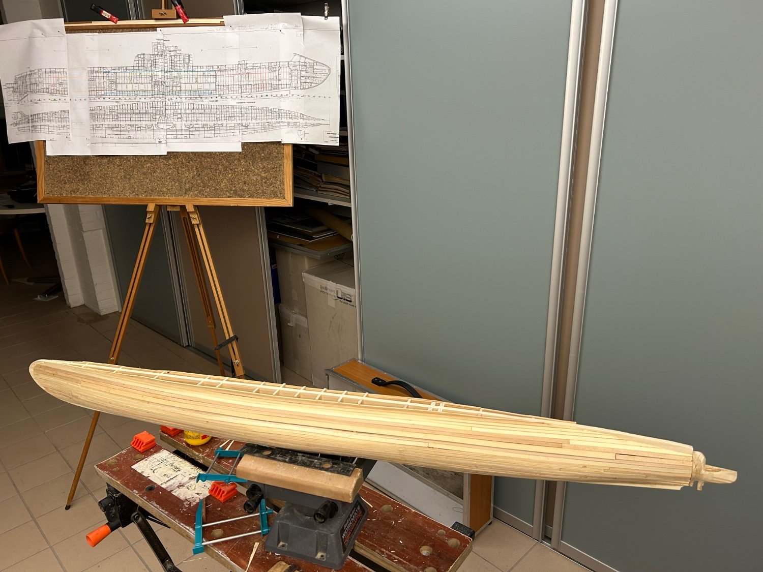
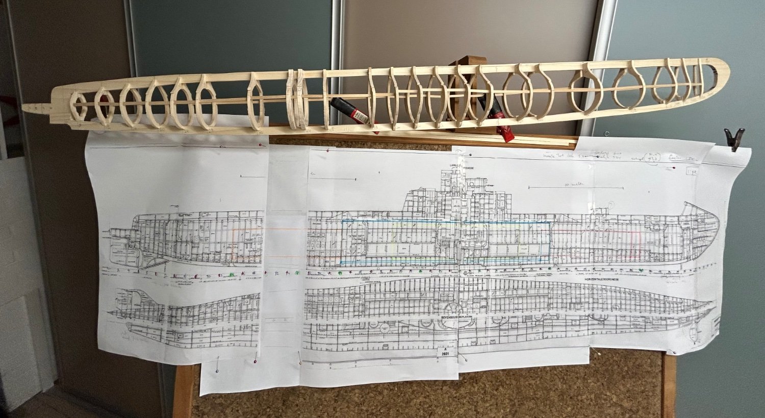
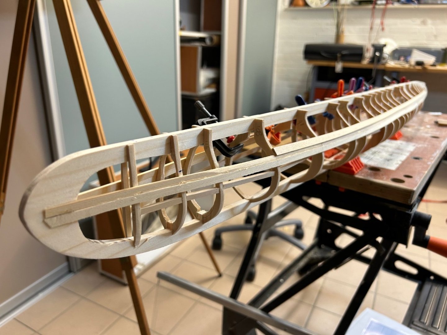
Reached a milestone in that the planking of the hull is complete! I cut my planks myself out of pine, they are 4mm wide and 2 mm thick and were cut from 2m by 5cm by 4mm planks. Just needed to avoid the knots in the wood. the keel of the boat has a thicker area, probably for ballast, as these boats suffered from instability, which is why a deck gun was not included in the class. The keel was not, however, detachable which was common in even older subs. next step is rough sanding, followed by a first coat of epoxy before splitting the boat as described in a previous post to have access to the inside.


-
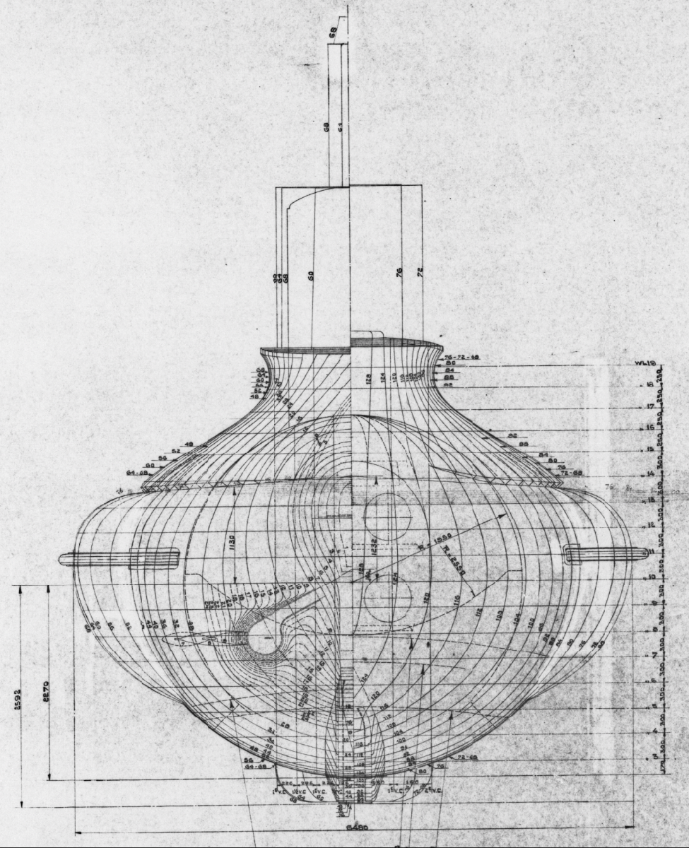
Thanks for your interests - the boat has at least 14 tanks, with the main ballast tanks in the saddles. Well visible on the frame-plan. yes lots of technical challenges - these 1931 boat was rather small - and so I will refrain from working torpedotubes! But I’m going to ensure I have spare power and signal wires going out of the water tight compartment so I can later consider moving periscopes and navigation lights.

-
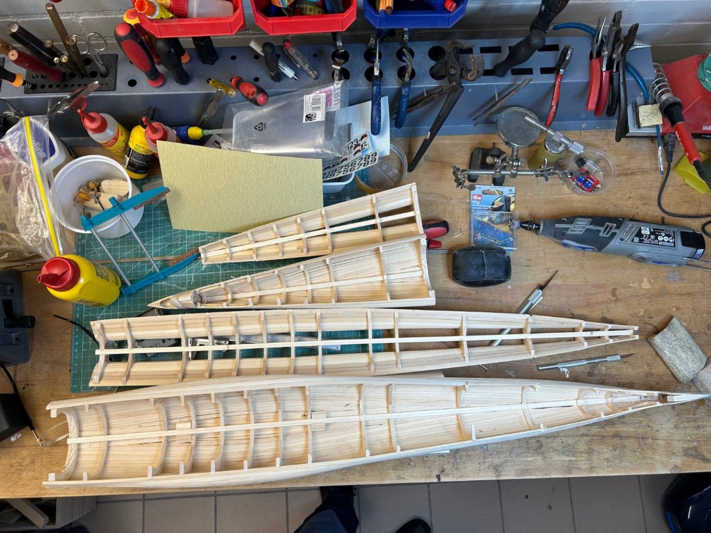
I’ve sort of worked out how the front diveplanes and the rear rudder assembly need to work. They will still be a lot of work, but I can get on with planking. To have access to the front and rear planes mechanisms, I’ve decided to split the boat both horizontally and vertically. Vertically with a bayonet which will open the water tight compartment, and horizontally for maintenance. Horizontally the boat will split along the “drainage line” where the bottom hull meets the deck section. That is the top plank visible in the photo that overlaps the plank below. Those are not glued together so once planking is complete, I will cut the frames along that line. in the stern, a solid block of wood is mounted that will hold the pushrods for the rudder and diveplanes.

-
All frames now glued to the keel, and I inserted small sticks between the frames which gives the hull rigidity. Before planking, I have to assure myself I can install the rudder/diveplanes assembly in the stern, and the bow planes in the bow. The boat is so narrow at this points (around 2cm), that I have to have a clear idea of the controls on the planes and rudders before closing the hull!! started with the bow planes, which as the photo on the 1st post shows, rotate upwards and then fold back when the sub is on the surface. I made a brass assembly where two cogwheels control the dive angle and the vertical rotation, and then a pushrod can fold the planes against the hull. it sort of works, but I have a long list of modifications before I can make a true prototype. And yes, the planes themselves will get shaped!


-
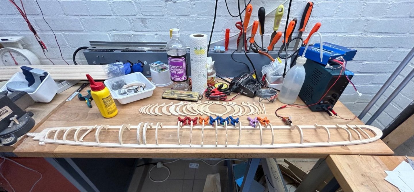
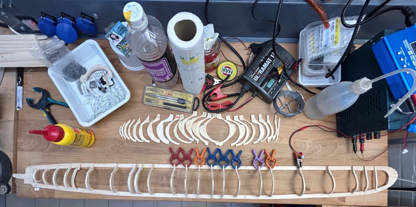
I finished the sawing of the frames, and placed the half-frames loose on the “keel”. It’s clearly a more difficult shape, with the saddletanks in the middle and a suddenly widening keel below them. I also had to take into account the space for the watertight cylinders and for the prop axes as drilling will be harder once the hull is planked. the two thicker frames is where the hull will be cut to access the insides.
-
We all struggle with these calculations! there are some formulas that convert prop rpm and pitch into speed, and like roger I suspect at a few 1000 rpm the prop will deliver the max speed that hull can reach. The hard calculation is if the motor can deliver the torque to the prop under load. I suspect your motor can only do that if you use a gearbox (dropping Reva for more torque). Dropping the voltage on a brushed motor will drop torque. Brushed motors like to run at their rated rpm. but on a brushless motor which typically has ample torque that is exactly what you do. These have kV indications, being rpm per volt, so a 1000kV brushless motor at 12 volt delivers 12000 rpm (too much) so you could run that at lower voltage. You likely would need a 300-700kV brushless motor. I would couple a shaft and prop to your motor in a test rig, hook it up to a ESC and test if it runs and does not get too hot (and how much power it draws).