James H
-
Posts
6,043 -
Joined
-
Last visited
Content Type
Profiles
Forums
Gallery
Events
Everything posted by James H
-

build review L4 Engine - Teching - vie EngineDIY (Build Review)
James H replied to James H's topic in Non ship-related reviews
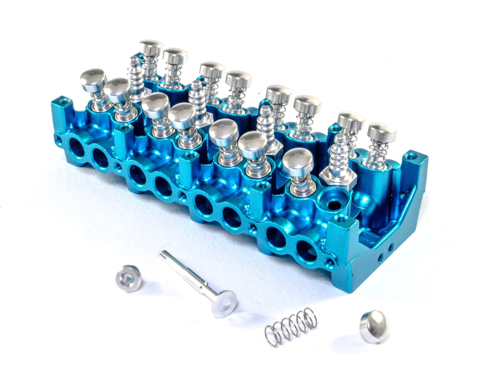
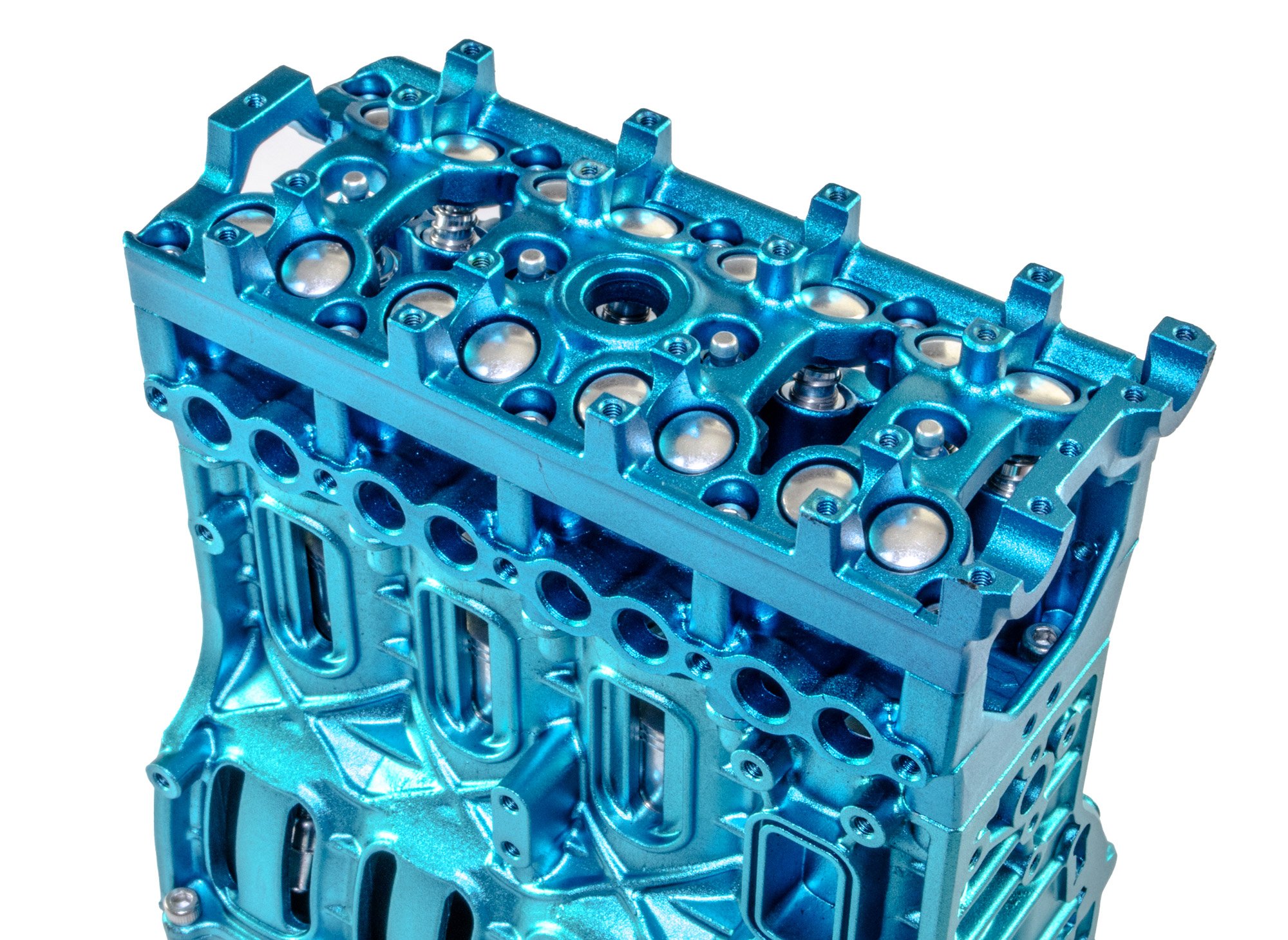
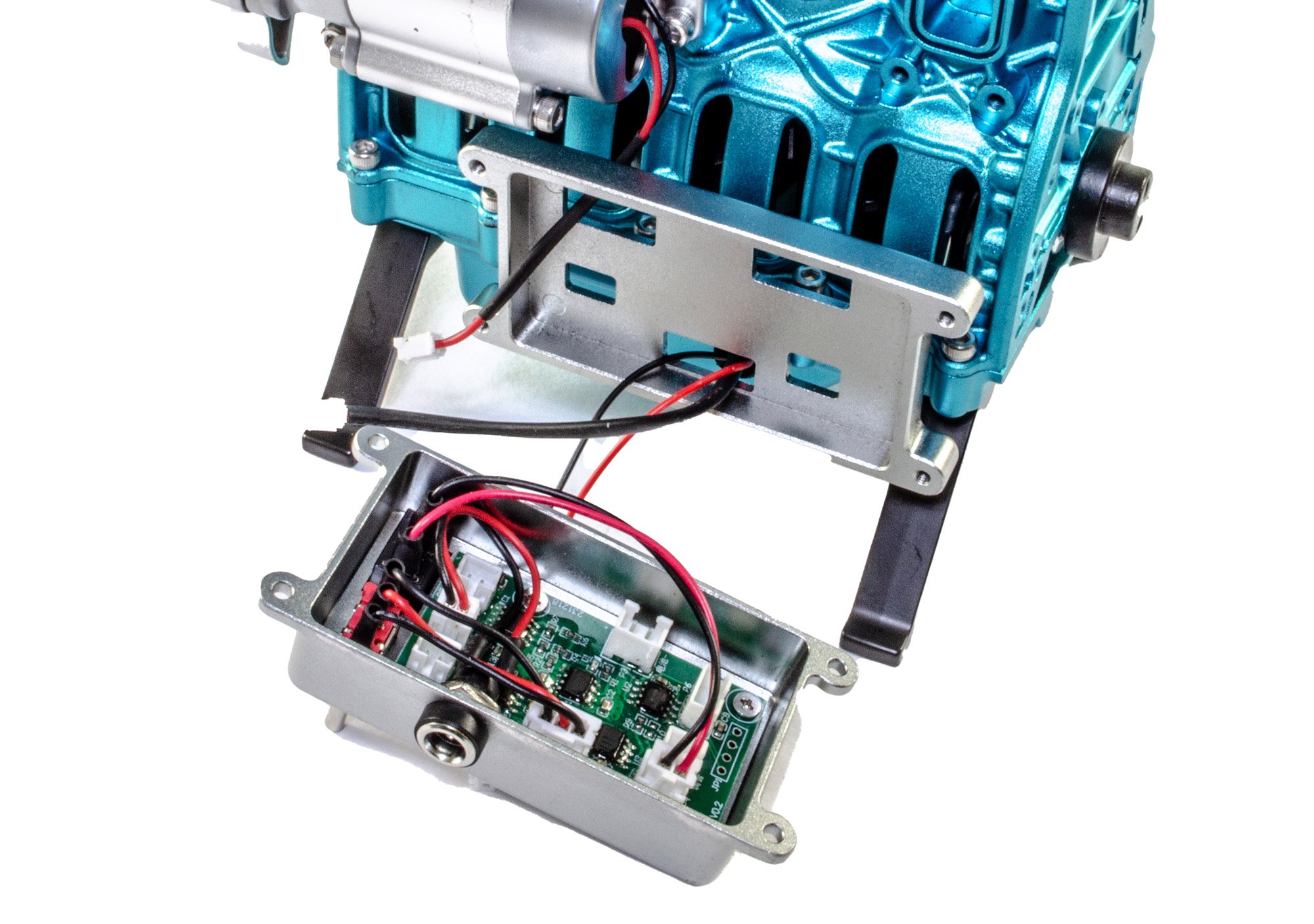
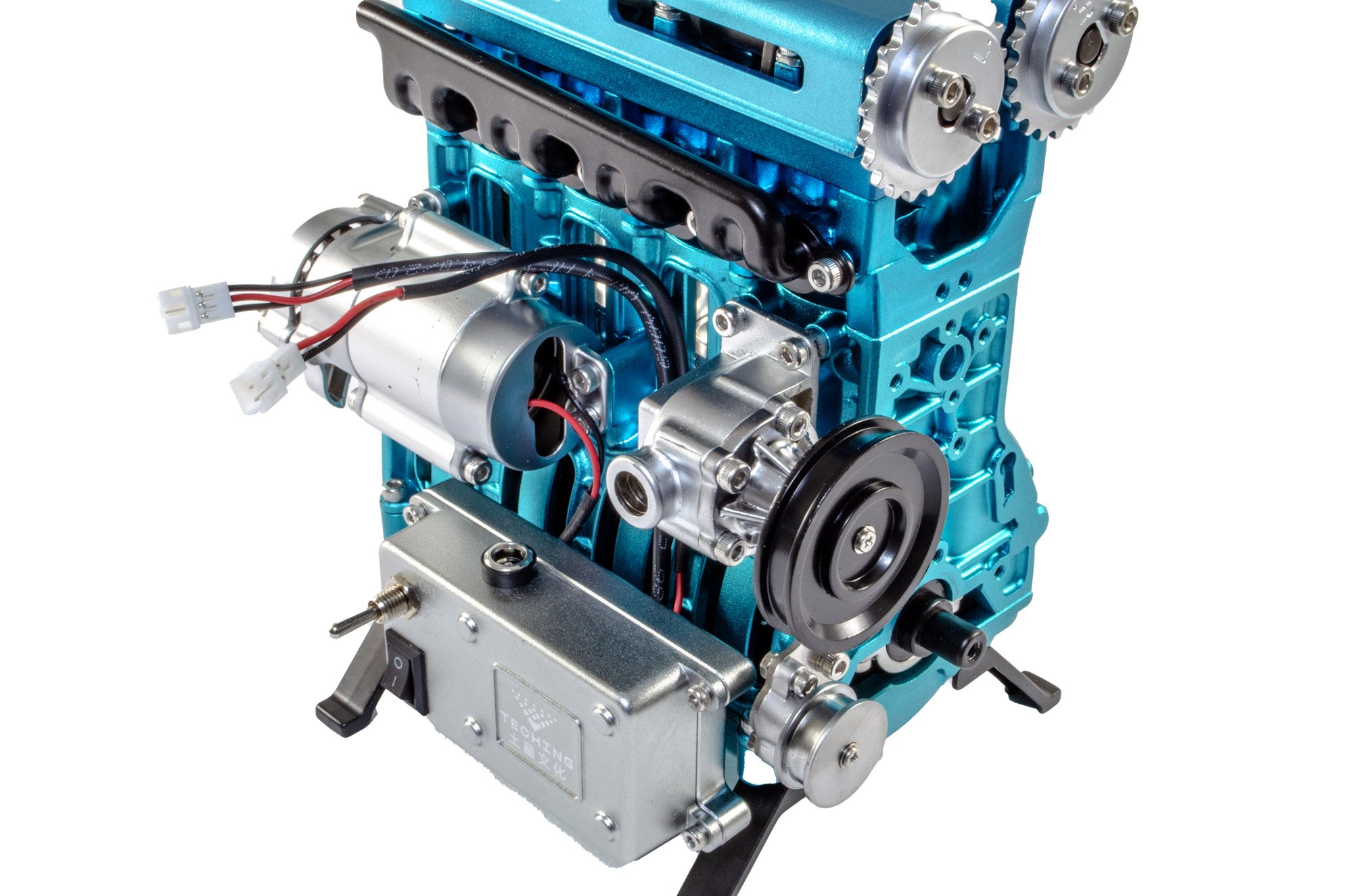
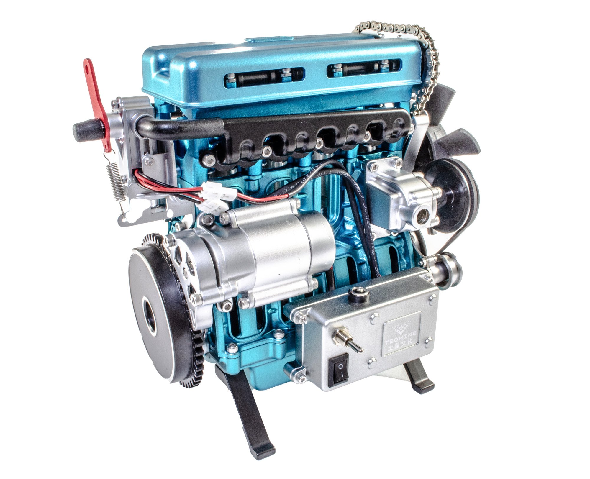
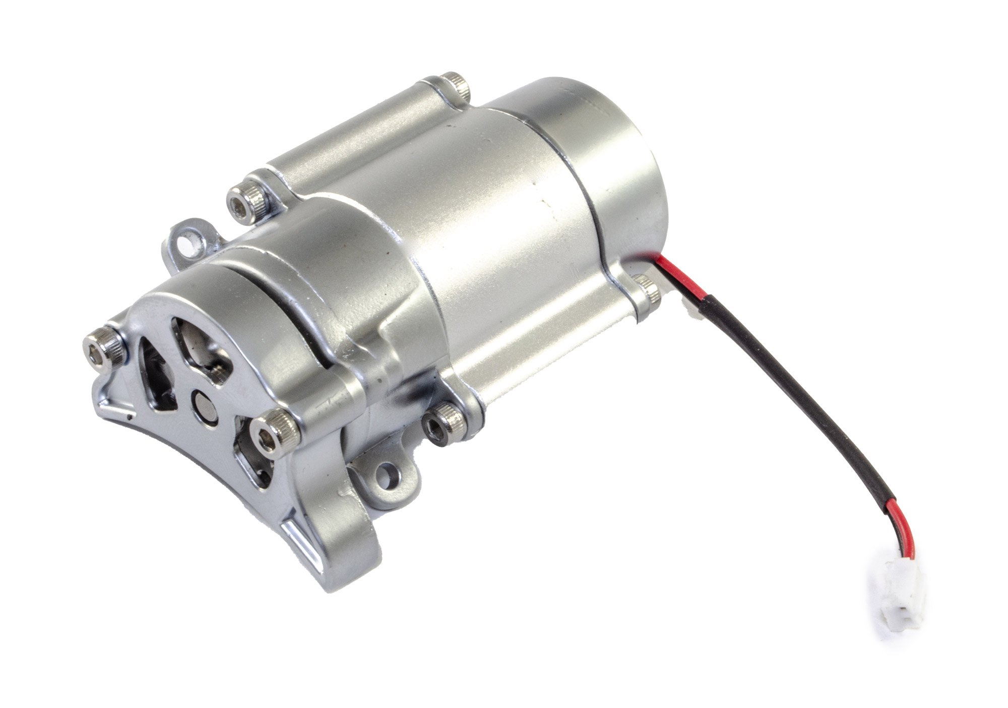
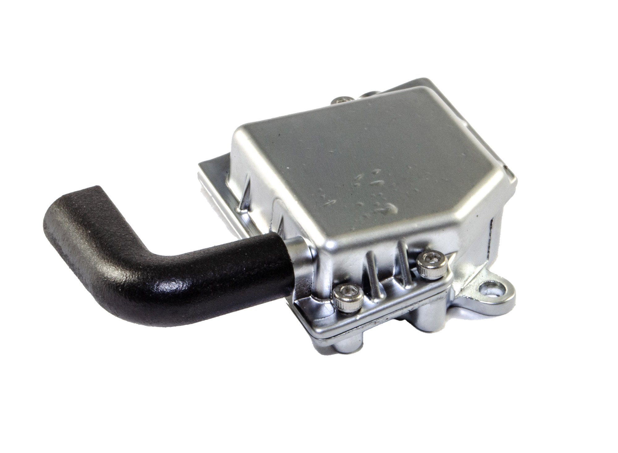
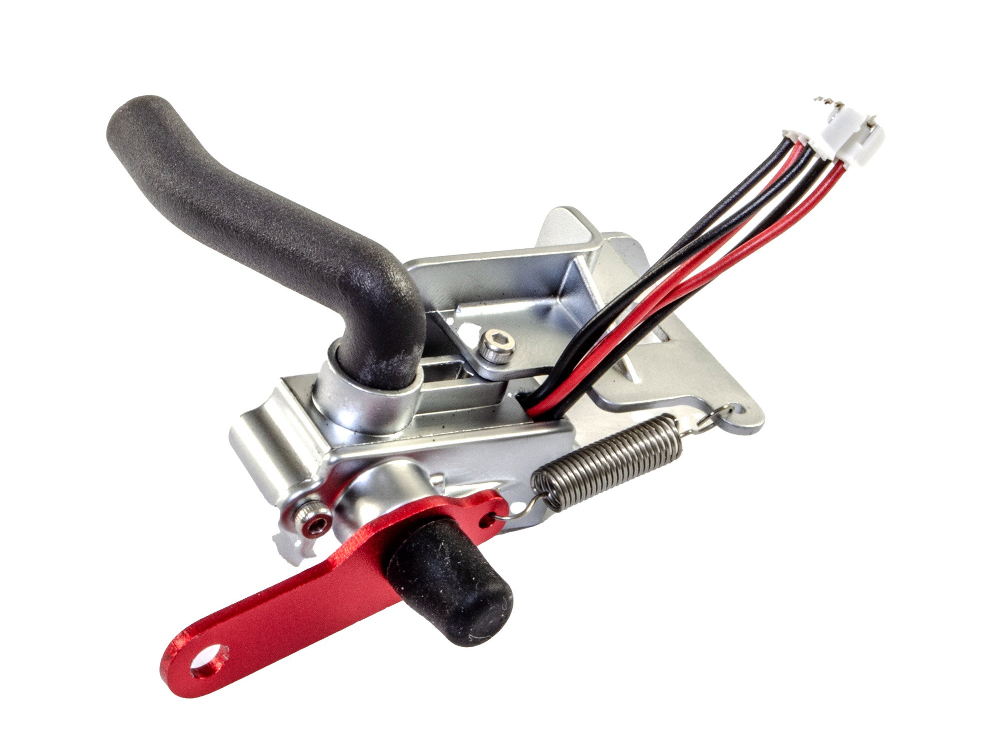
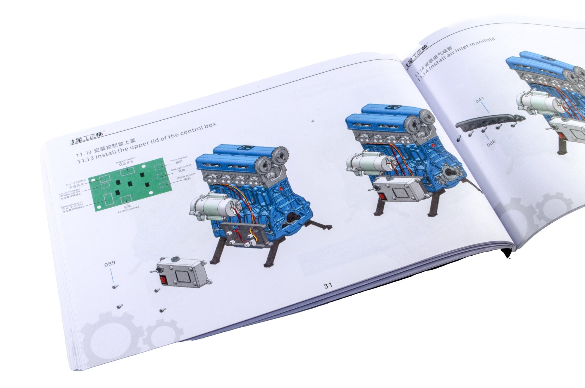
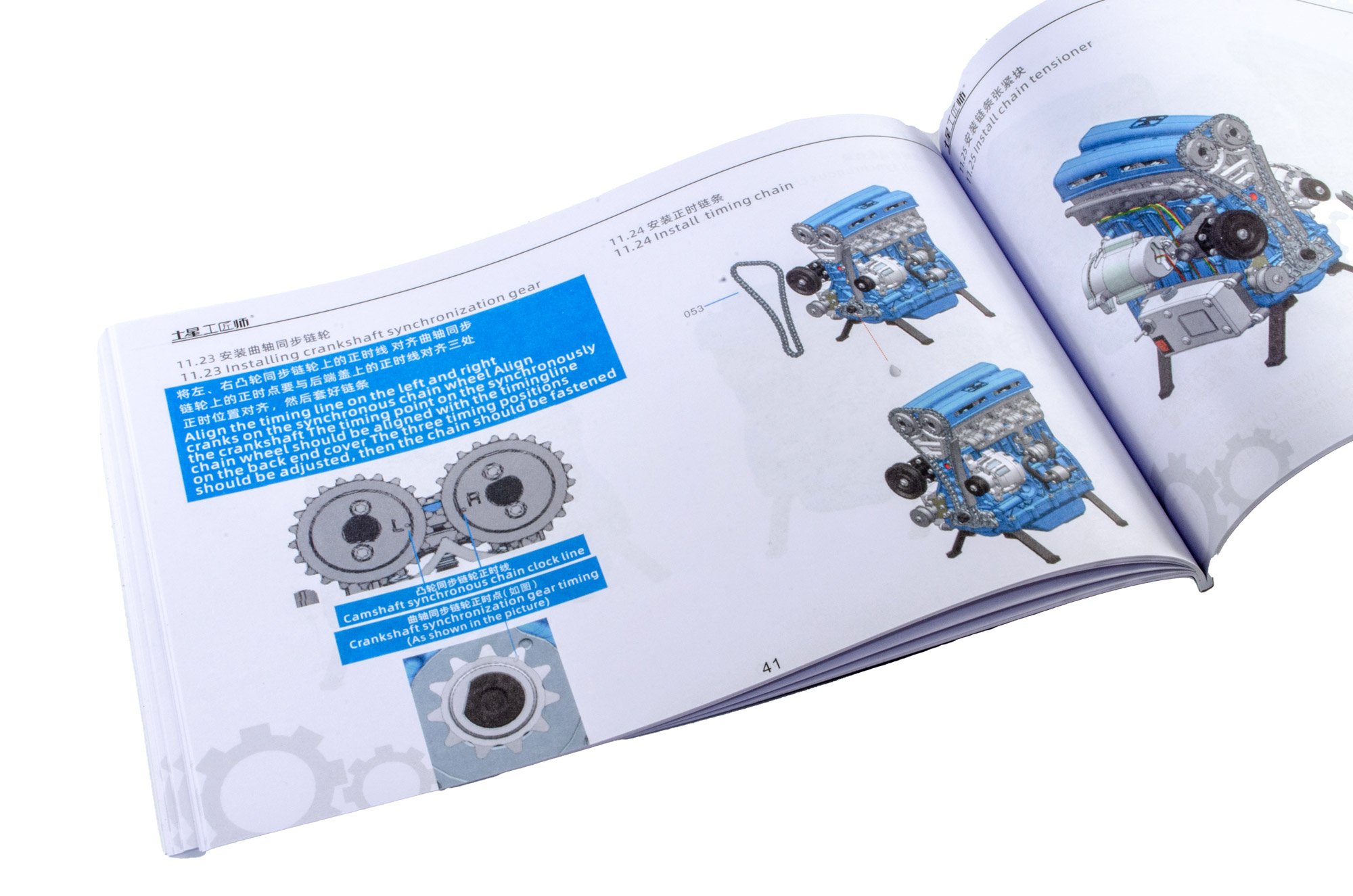
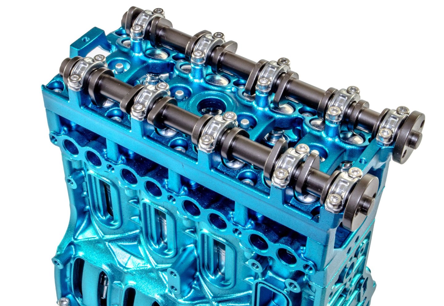
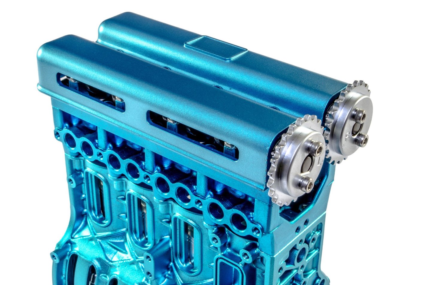
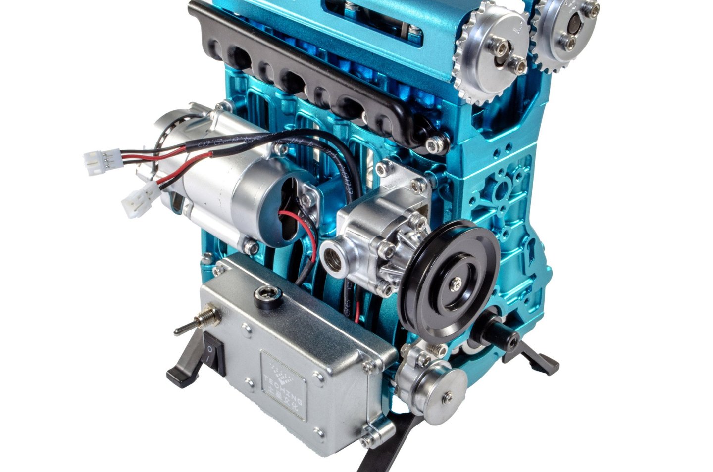
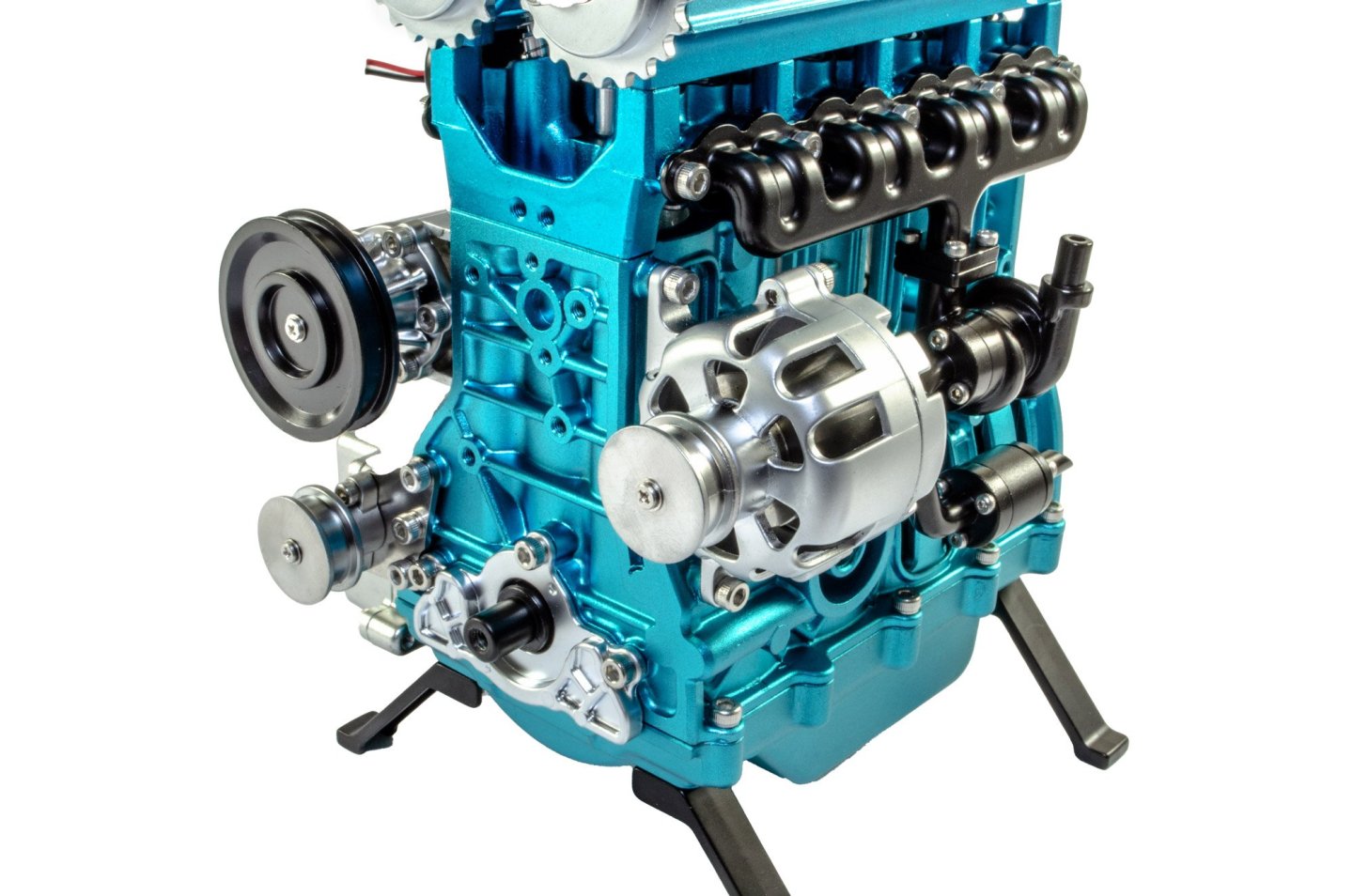
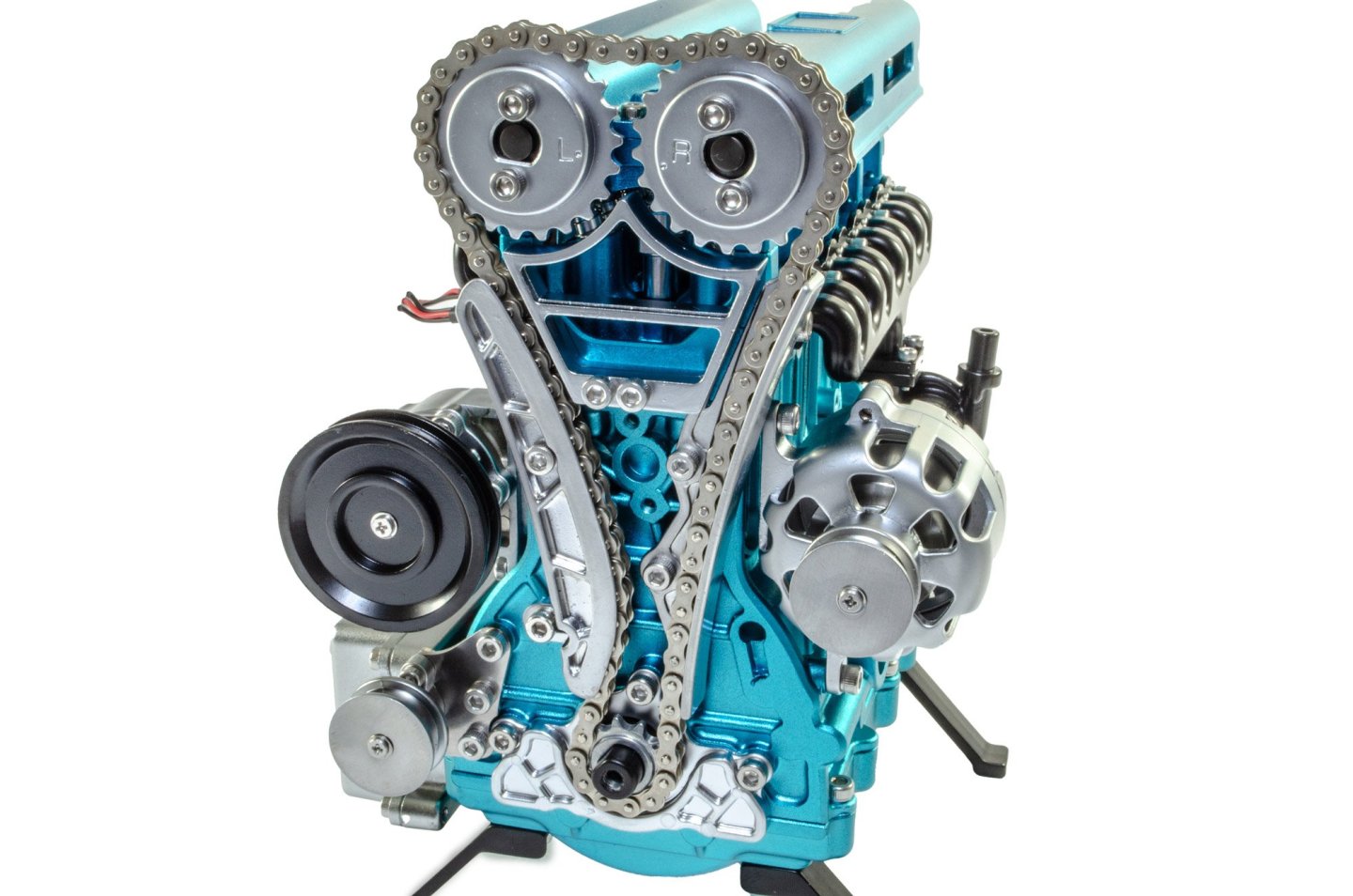
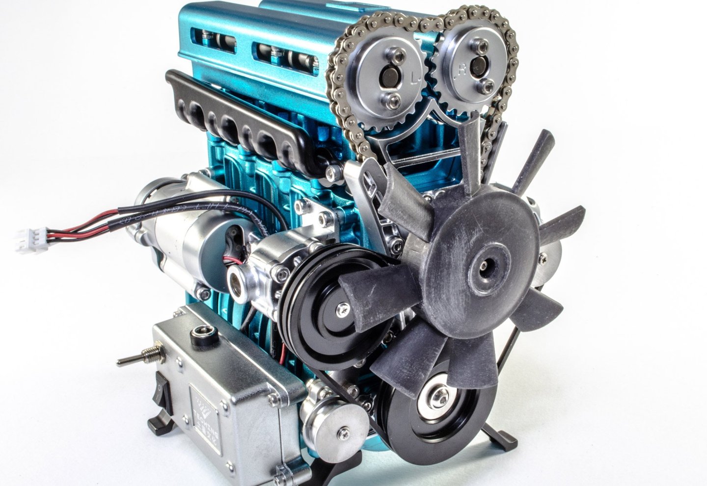
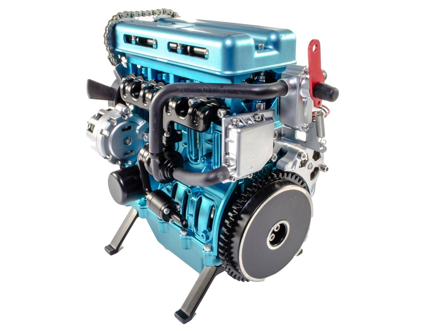
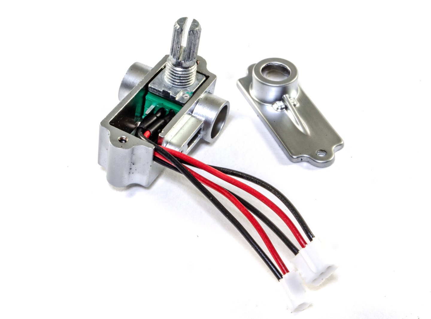
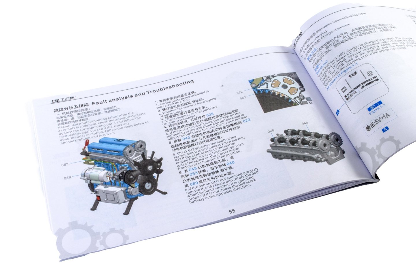
At this point in the build, the cylinder head is to be built. First, I add the four spark plugs, seen here in silver. Now, the pistons are fitted, with some light oil as lubrication. The manual tells you when this is to be added. You'll need to source your own lube, at least if you live in the UK, as it's omitted from the kits I've built. The cylinder head case is now fitted, and the whole assembly bolted to the crankcase. Of course, this engine will need two camshafts, and here they are, bolted in position and lubricated. When secure, the valve cover is installed. The control box is now bolted to the crankcase and the electric motor also fitted. The cables from this and the circuit are now routed into the control box. The belt pulleys are now fitted. Setting up the engine timing is a breeze. These two gears need to be set as thus, with the two pips aligning. The lower gear just needs to have a pip aligned with a mark on the crankcase. With that satisfied, the drive chain is now added, along with the track and tensioner. I found the midway point to be good for setting up the chain tensioner, so the belt and everything moved freely. Now the fan belt. Followed by the crankshaft pulley and the accelerator potentiometer. The engine is now completed! The conclusion and video will follow over the weekend...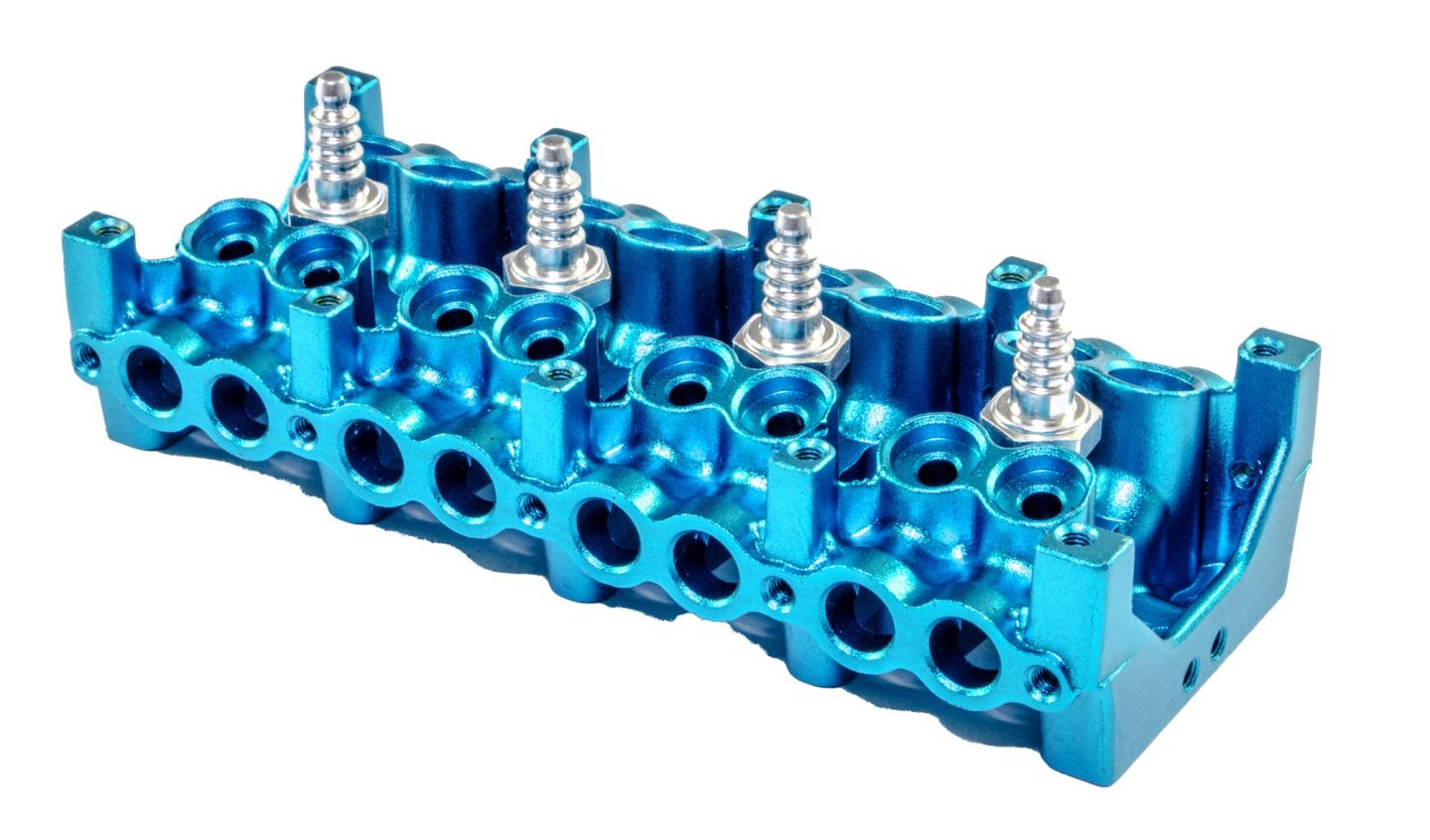


-
build review L4 Engine - Teching - vie EngineDIY (Build Review)
James H replied to James H's topic in Non ship-related reviews
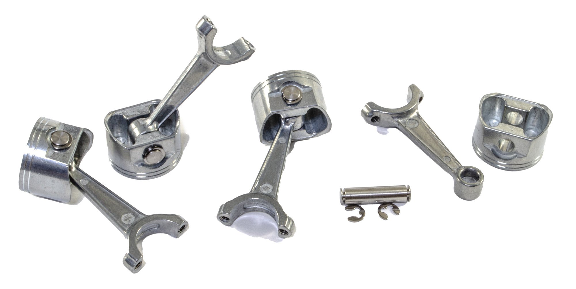
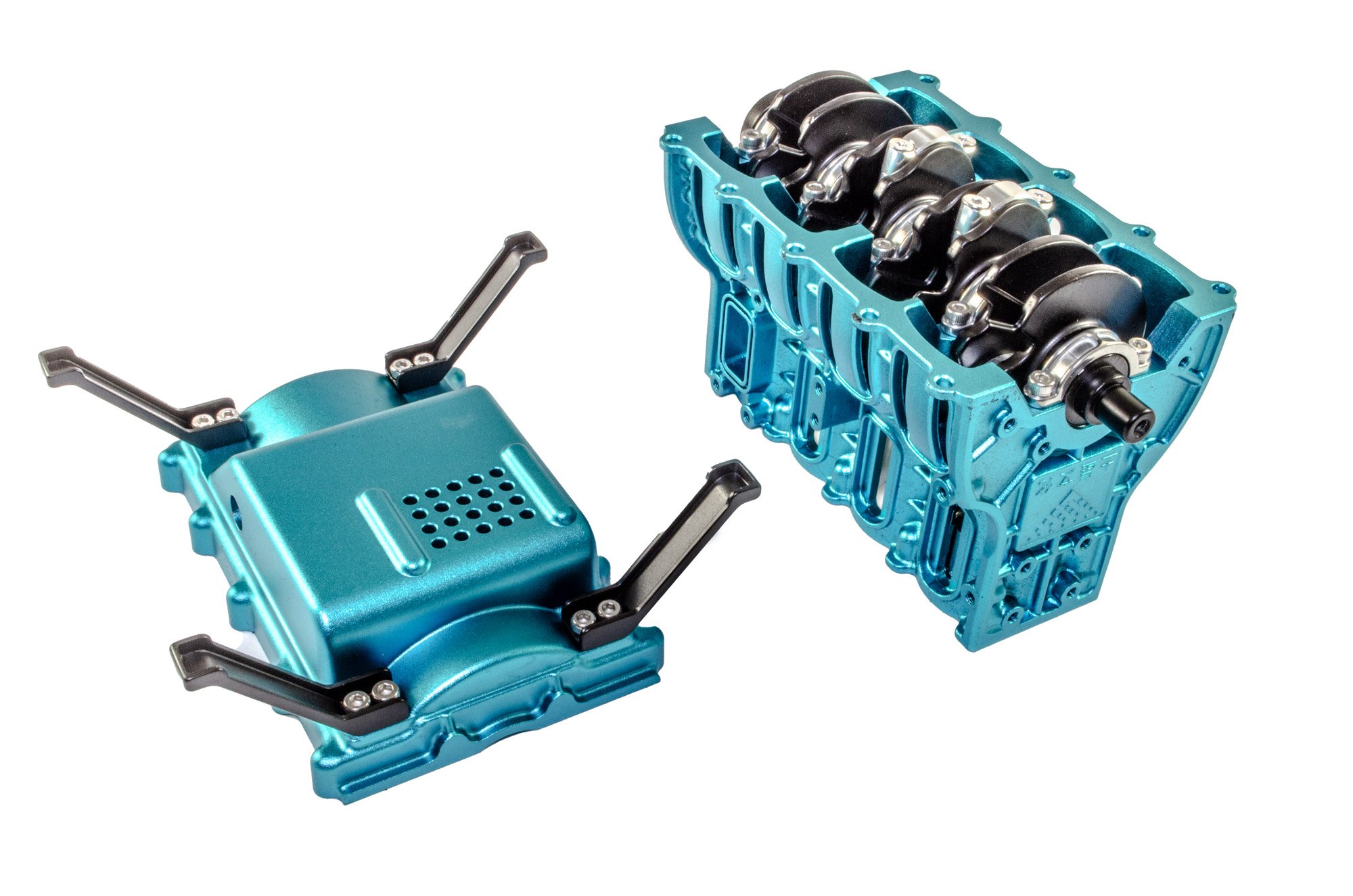
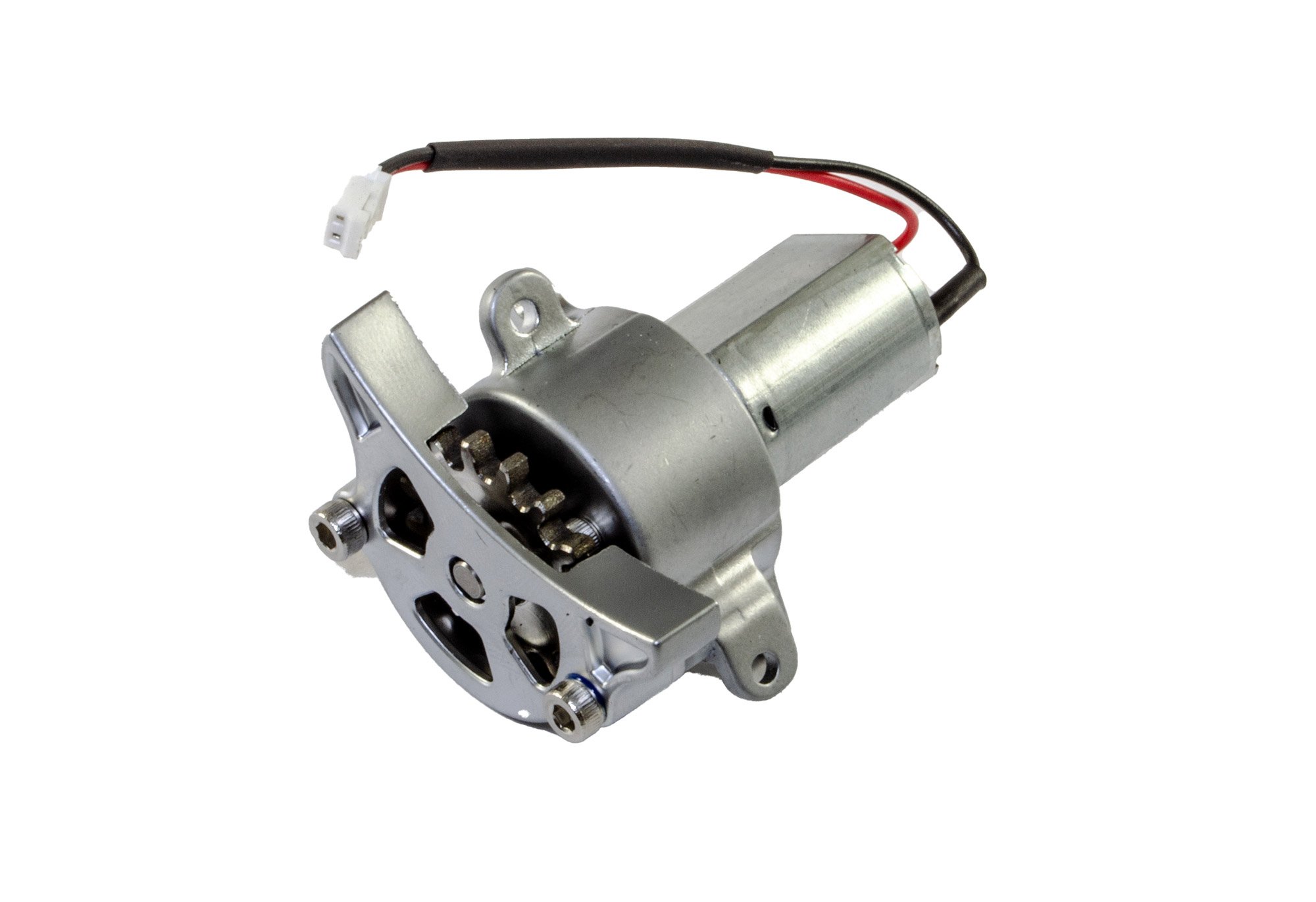
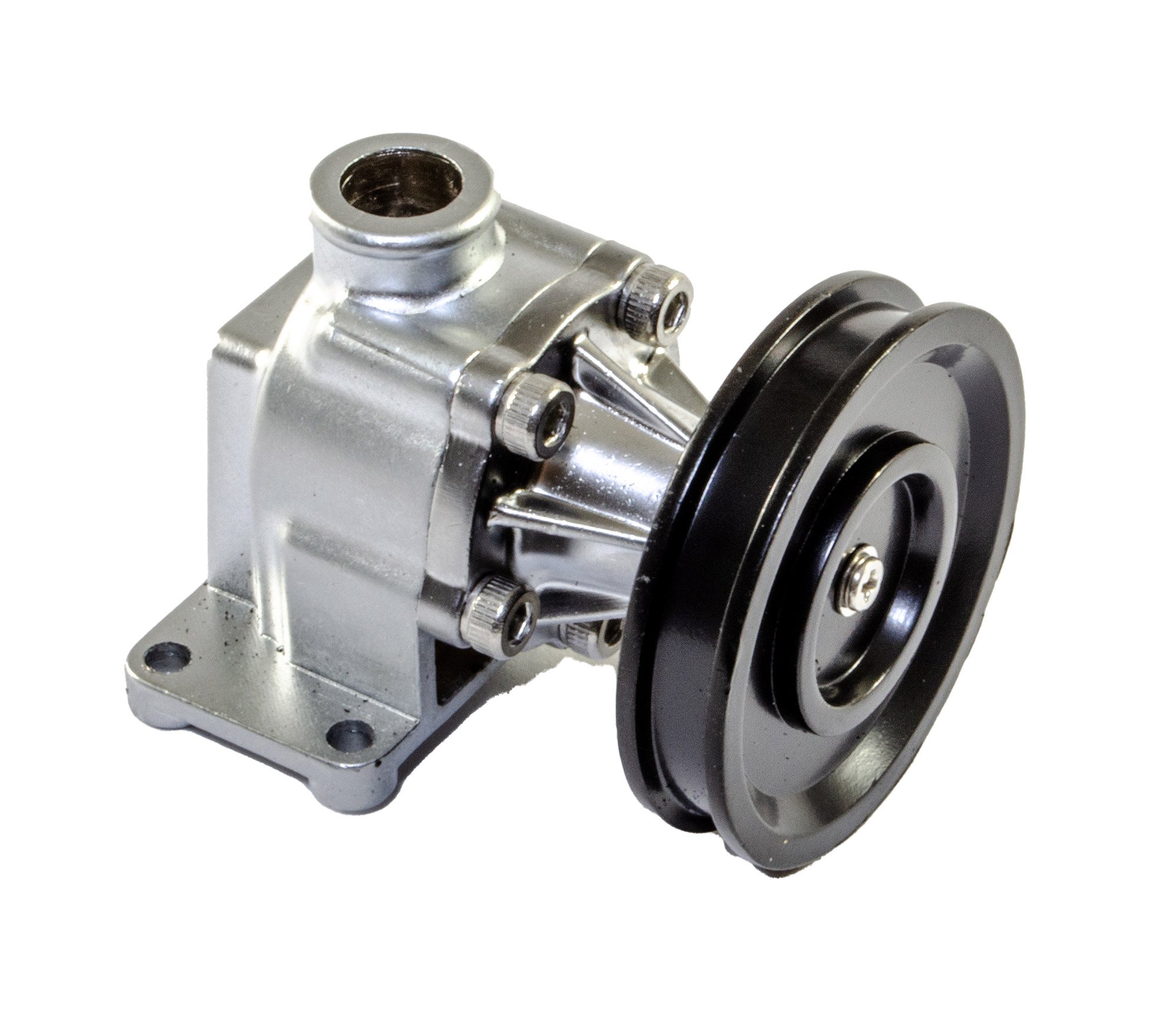
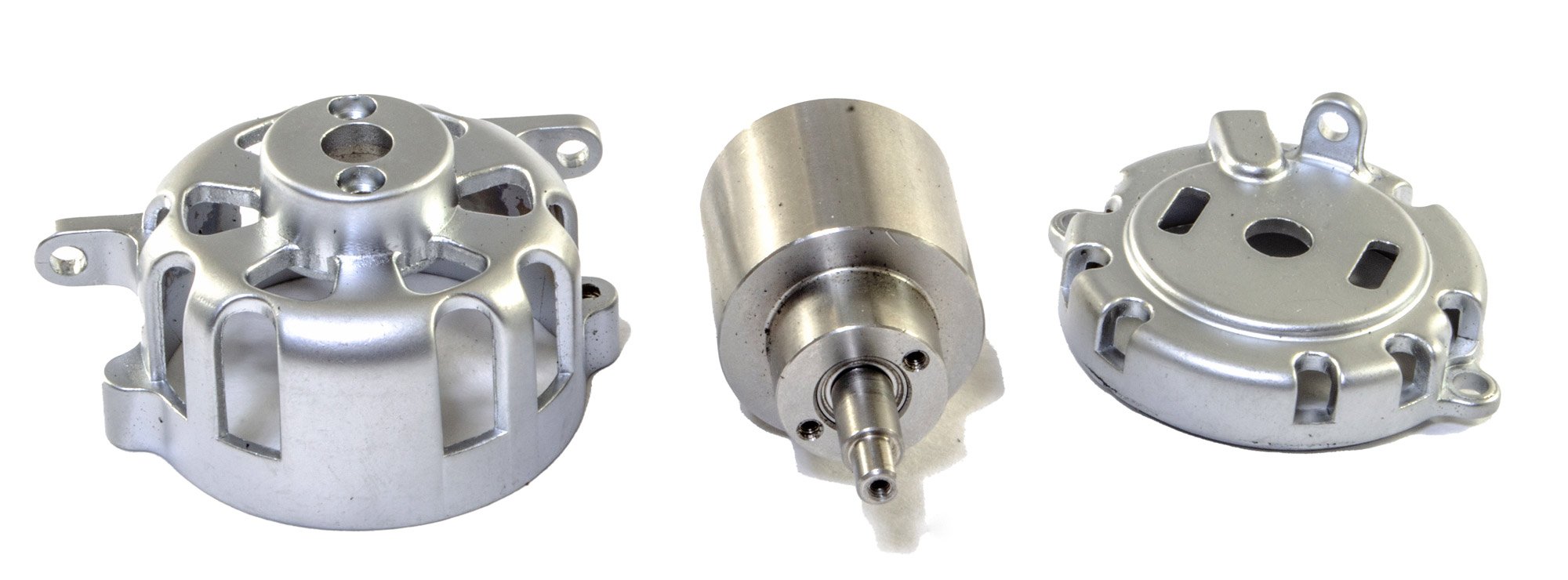
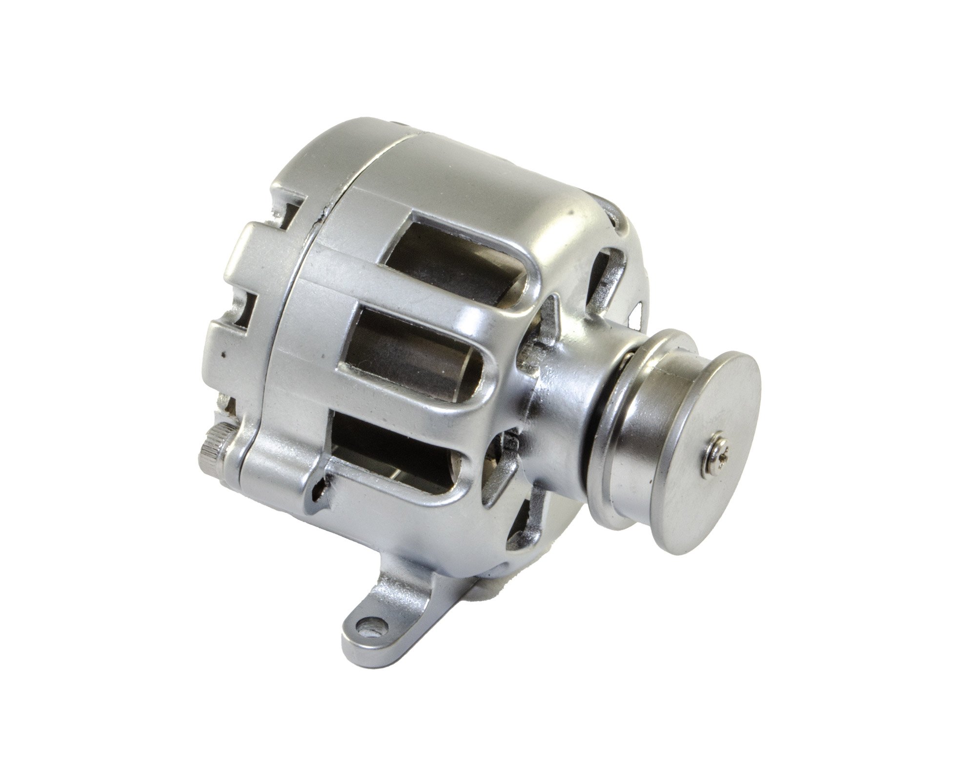
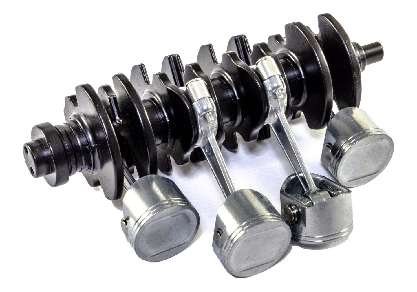
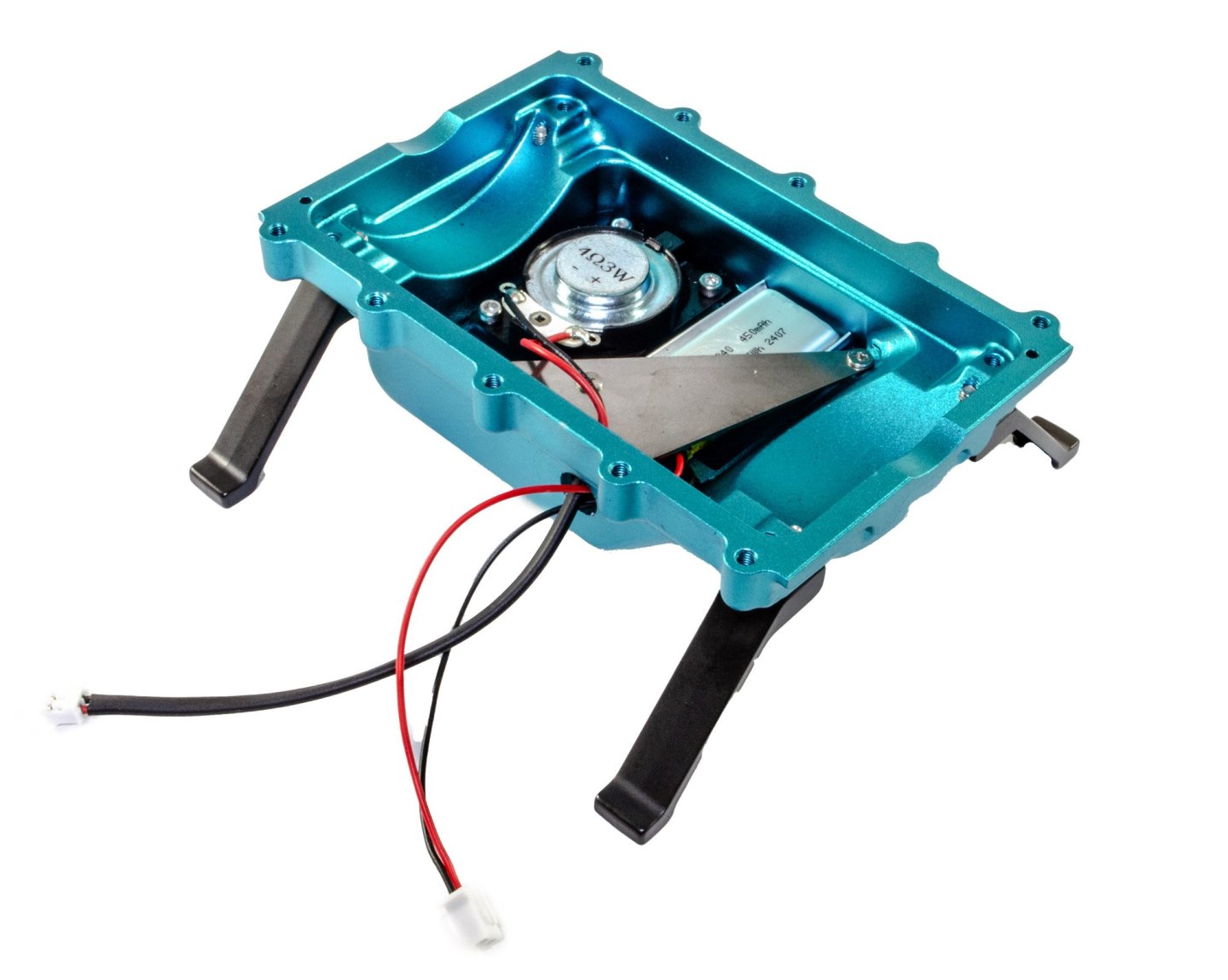
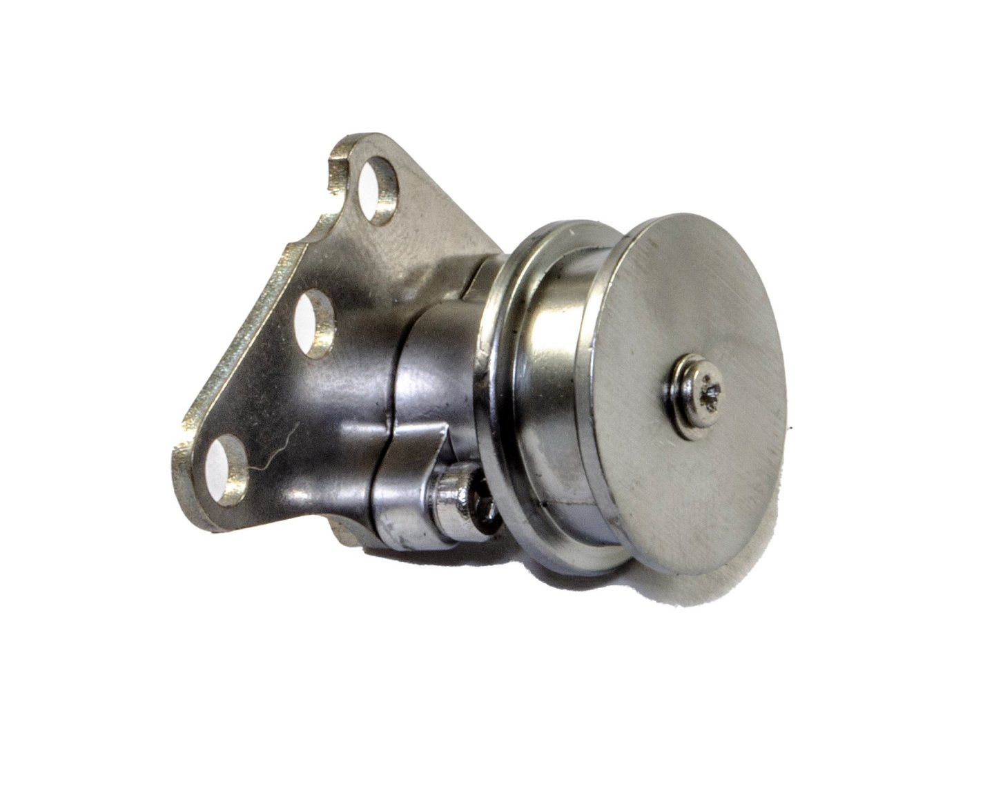
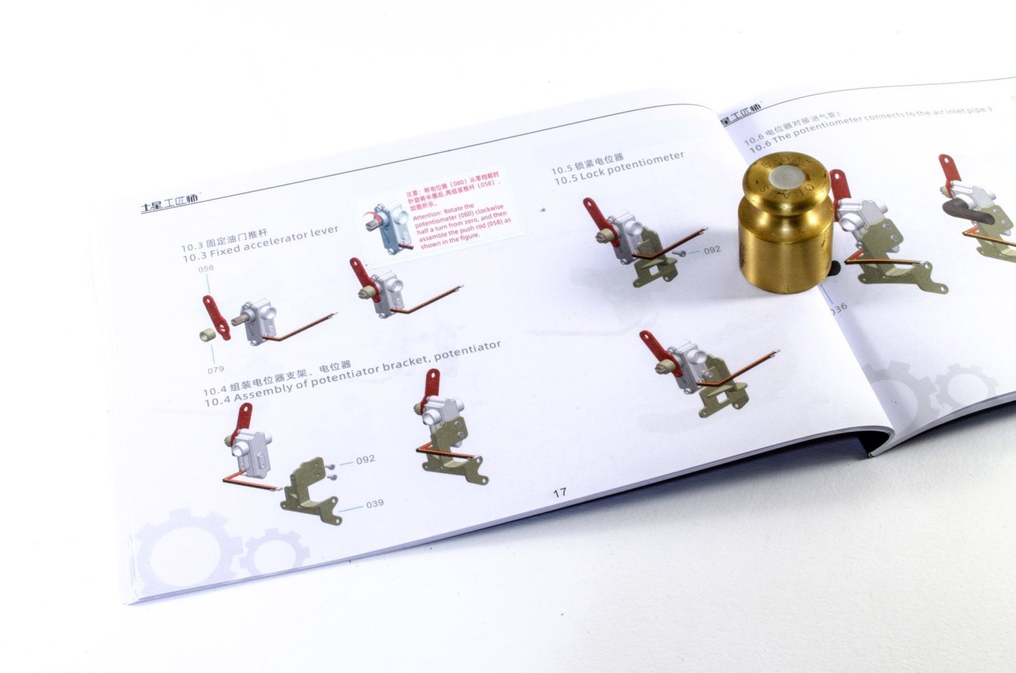
The build starts with building the four pistons. These are quite simple and consist of the pushrod and piston heads, held in place with a steel pin and two circlips. These are also lubricated with a little light oil before assembly. The pistons are then connected to the crankshaft. This assembly is now fitted to the crankcase. At this point, I hadn't noticed that I'd put the crankshaft in the wrong way around, so you'll see it like this for a few shots. In fairness to me, the images in this manual do look a little muddy in places, and I there are some errors too with images being mirrored or numbered incorrectly. Having said that, the model is generally easy to build as the parts look quite distinct. Here you also see the sump, with the display feet fitted. Unlike the V8 I built, this model has sound, with the speaker in the sump. This is also where the battery hides out. The exhaust system is now built up out of multiple parts that need to orientate correctly. The electric motor is then fitted into its forward housing, along with its gear and fence. Once complete, the rear shell is then fitted, enclosing the electric motor. It's now the turn of the water pump to be built. While this does have bearings and rotates, it's only representative here and will not be used to pump water! A belt pulley is now built up, using more bearings. This engine pulley is a little more complex, but is so engineered that it rotates very smoothly, and will of course be used to assist in the operation of this engine. The air filter is merely decorative, but as this engine has one, it needs to be fitted. And this little unit contains a potentiometer. When installed, this will have the effect of increasing and decreasing the engine's revs, and therefore its speed. This needs to be set up in a specific way so that it operates from a neutral position. The crankcase can now be bolted to the sump. It's here that you will need that modified hex key. ......more soon.


-
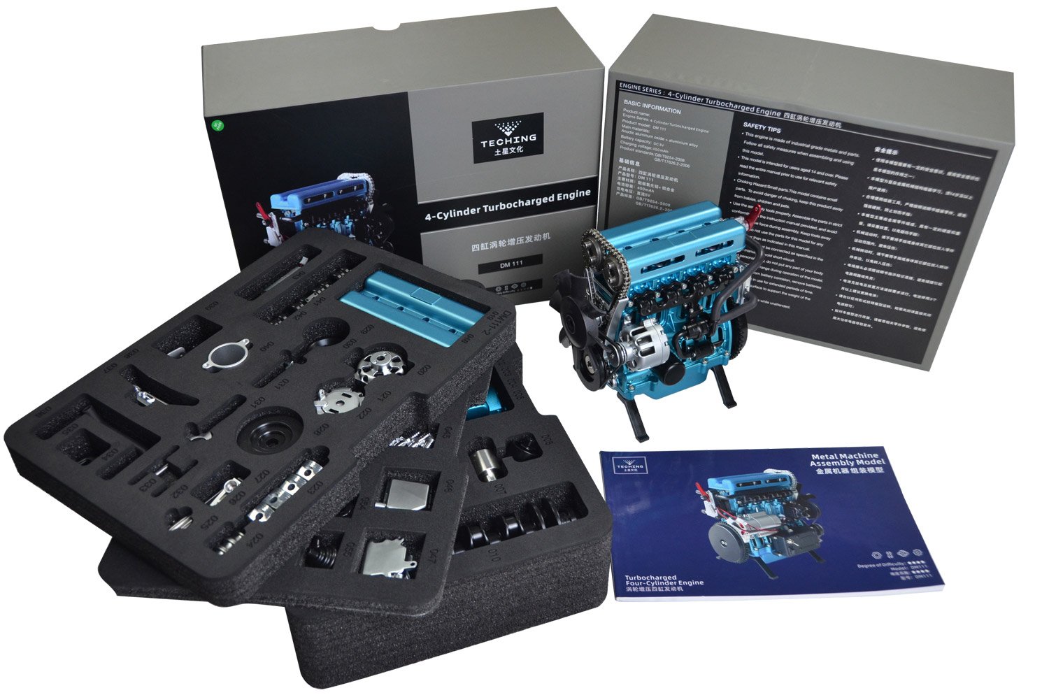
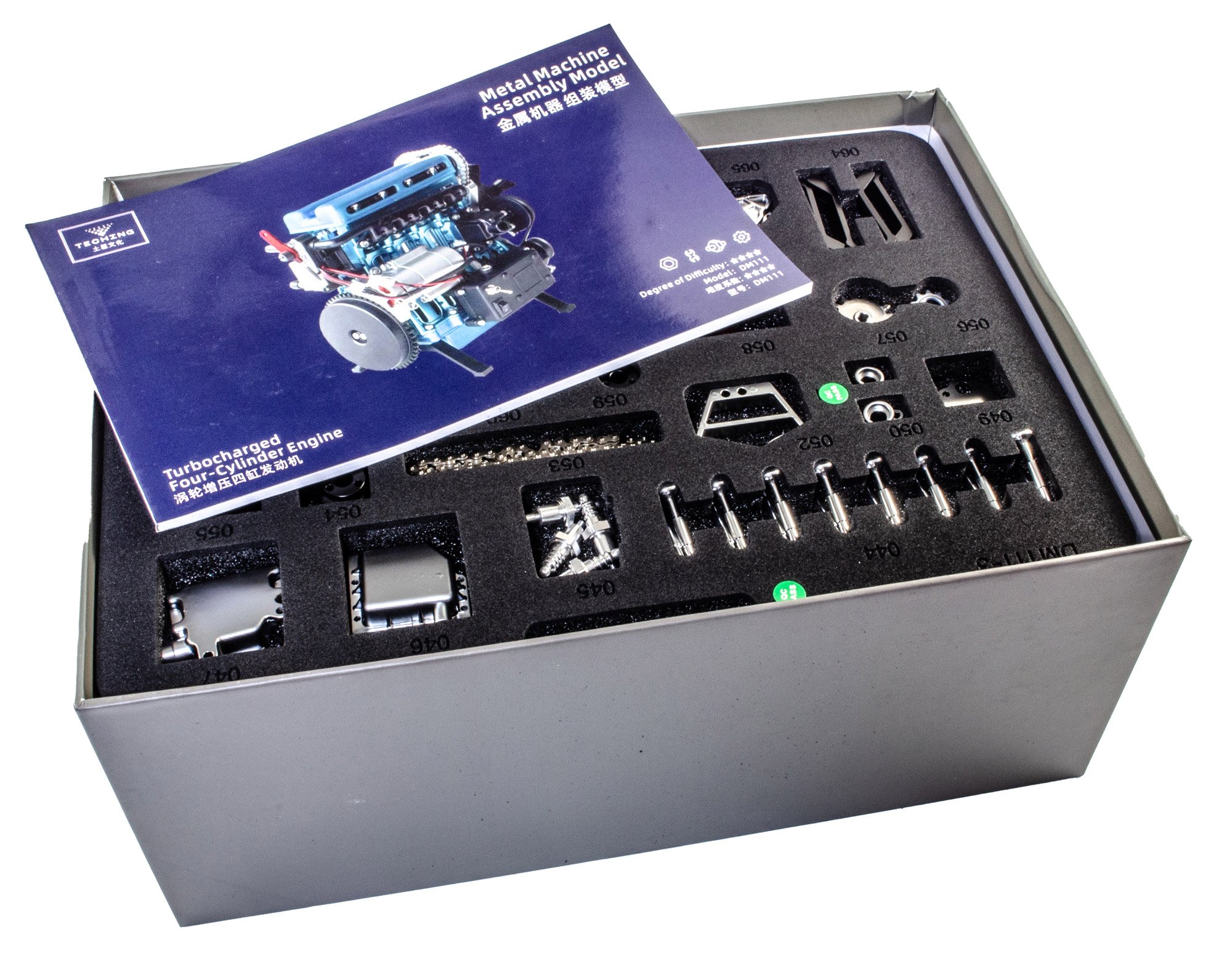
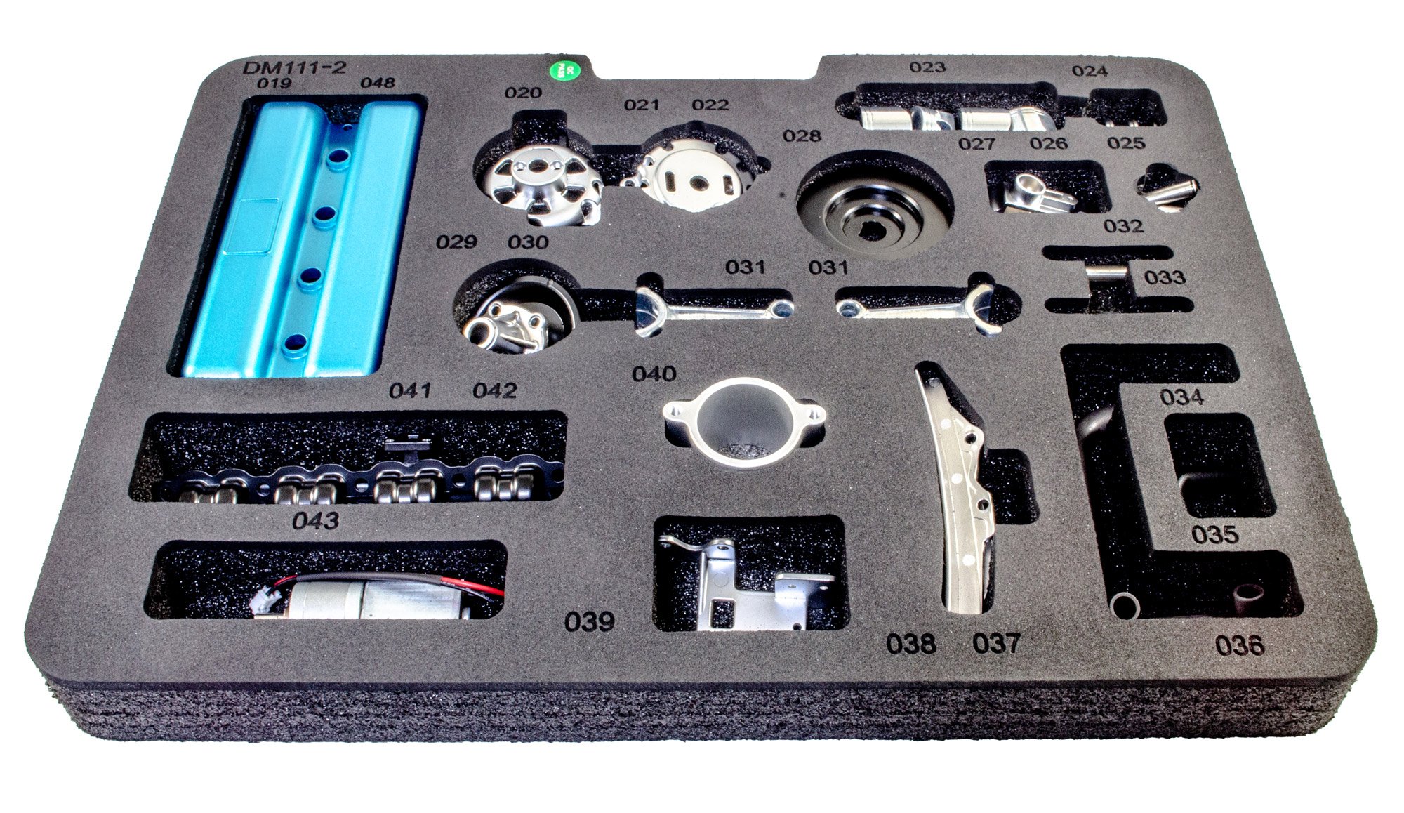
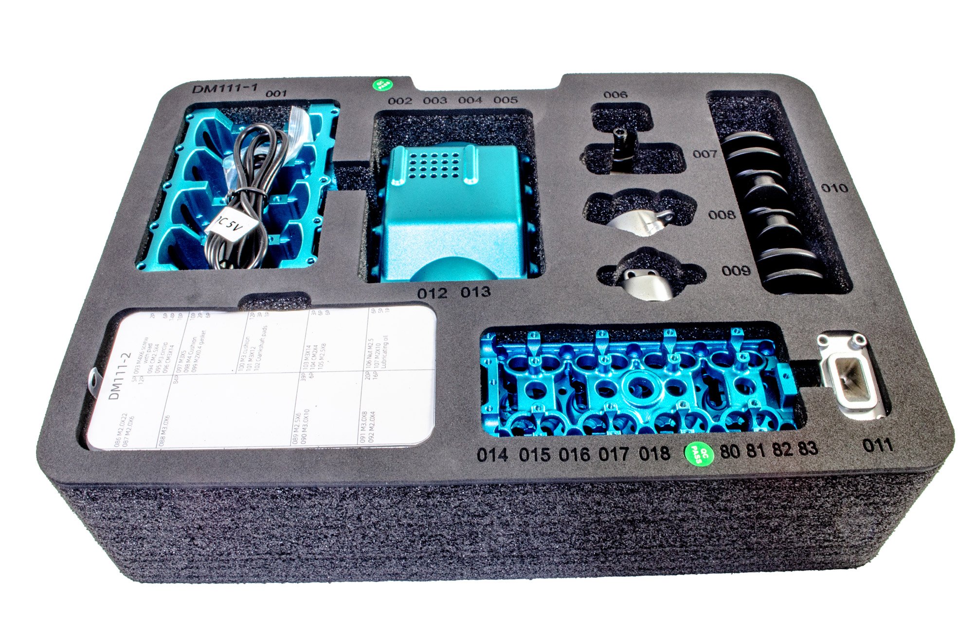
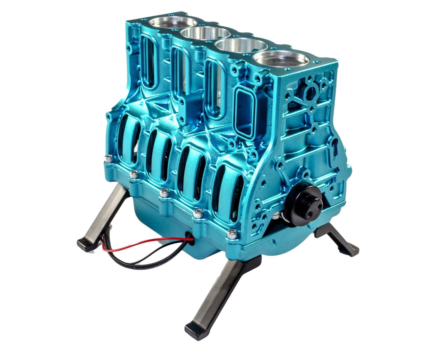
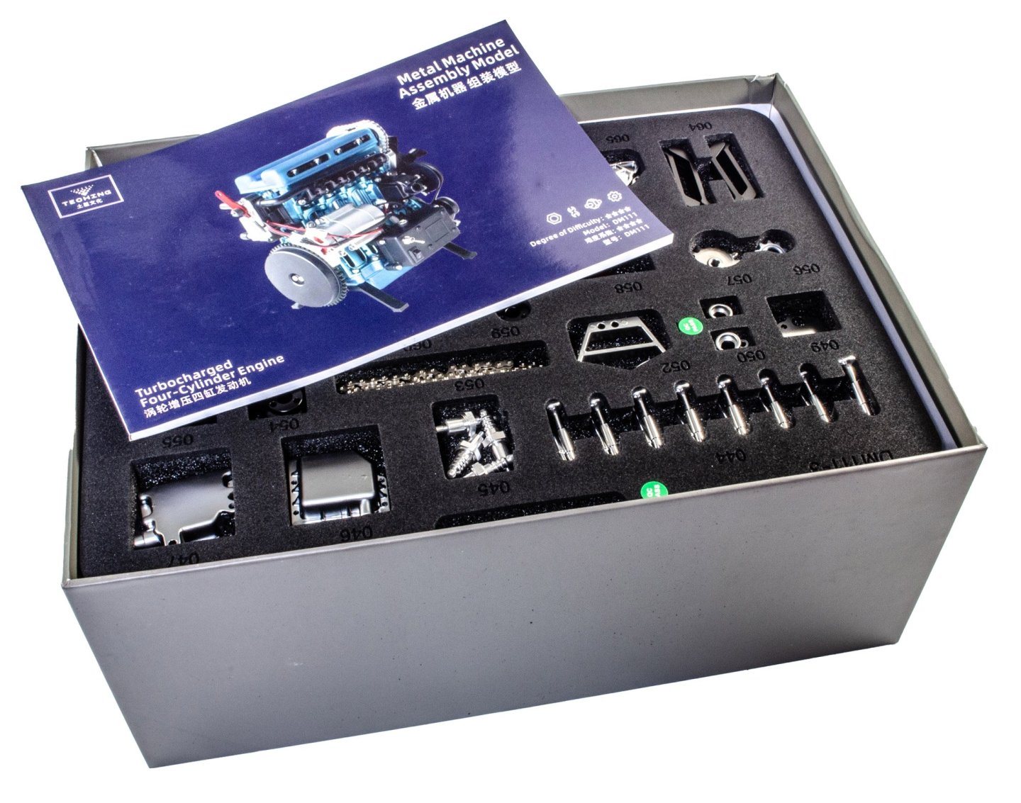
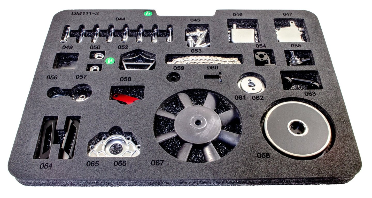
L4 Engine - Teching - vie EngineDIY (Build Review) Available from EngineDIY for $499.99 An L4 (straight-four engine, also referred to as an inline-four engine) is a four-cylinder piston engine where cylinders are arranged in a line along a common crankshaft. The majority of automotive four-cylinder engines use a straight-four layout, with the exceptions of the flat-four engines produced by Subaru and Porsche. Here, the layout is also very common in motorcycles and other machinery. Therefore the term "four-cylinder engine" is usually synonymous with straight-four engines. When a straight-four engine is installed at an inclined angle (instead of with the cylinders oriented vertically), it is sometimes called a slant-four. A four-stroke straight-four engine always has a cylinder on its power stroke, unlike engines with fewer cylinders where there is no power stroke occurring at certain times. Compared with a V4 engine or a flat-four engine, a straight-four engine only has one cylinder head, which reduces complexity and production cost. Abridged from Wikipedia. The kit This is another heavy kit, this time packed into an almost bomb-proof high density card box that even Apple would be proud of. The lid comes off real slow to allow for the air to get in there! The packaging is very attractive, with all panels adorned with photos and data. EngineDIY also say this of the kit: Product name: Inline four-cylinder engine model Material: aluminium alloy + stainless steel colour: blue Coloring process: anodizing Number of parts: 364+PCS Finished product size: 158.5*117*182mm Finished product weight: 1747g External power supply: DC 5V (USB cable charging) Lithium battery capacity: 500mAh Charging time: 2h Battery life: 30+min (when fully charged) Assembly time: 4h Skill level 4/5 There are THREE parts trays in this kit, with all parts being snugly held in a laser slot, with the part number engraved adjacent to the part. It's nigh on impossible not to be able to find a part quickly. It also needs to be known that all of the nuts, bolts, washers, and a number of other specific kit parts such as piston caps, springs, bearings, etc. are to be located in one of TWO compartmented tubs. These have part numbers on the lid of each compartment, making it a breeze to find what you need. Some tools are also included, but I decided to use my Wera tool set mostly. One bolt requires a modified (cut down) hex key, and this is included in the kit. A 72-page colour manual is included. This details the build in coloured illustration, along with text regarding the engine itself, and a complete parts chart. More very soon...


-
Kit review 1:25 Drakkar ‘Oseberg’ - Ships of Pavel Nikitin
James H replied to James H's topic in REVIEWS: Model kits
I hope you consider a build log for this? -
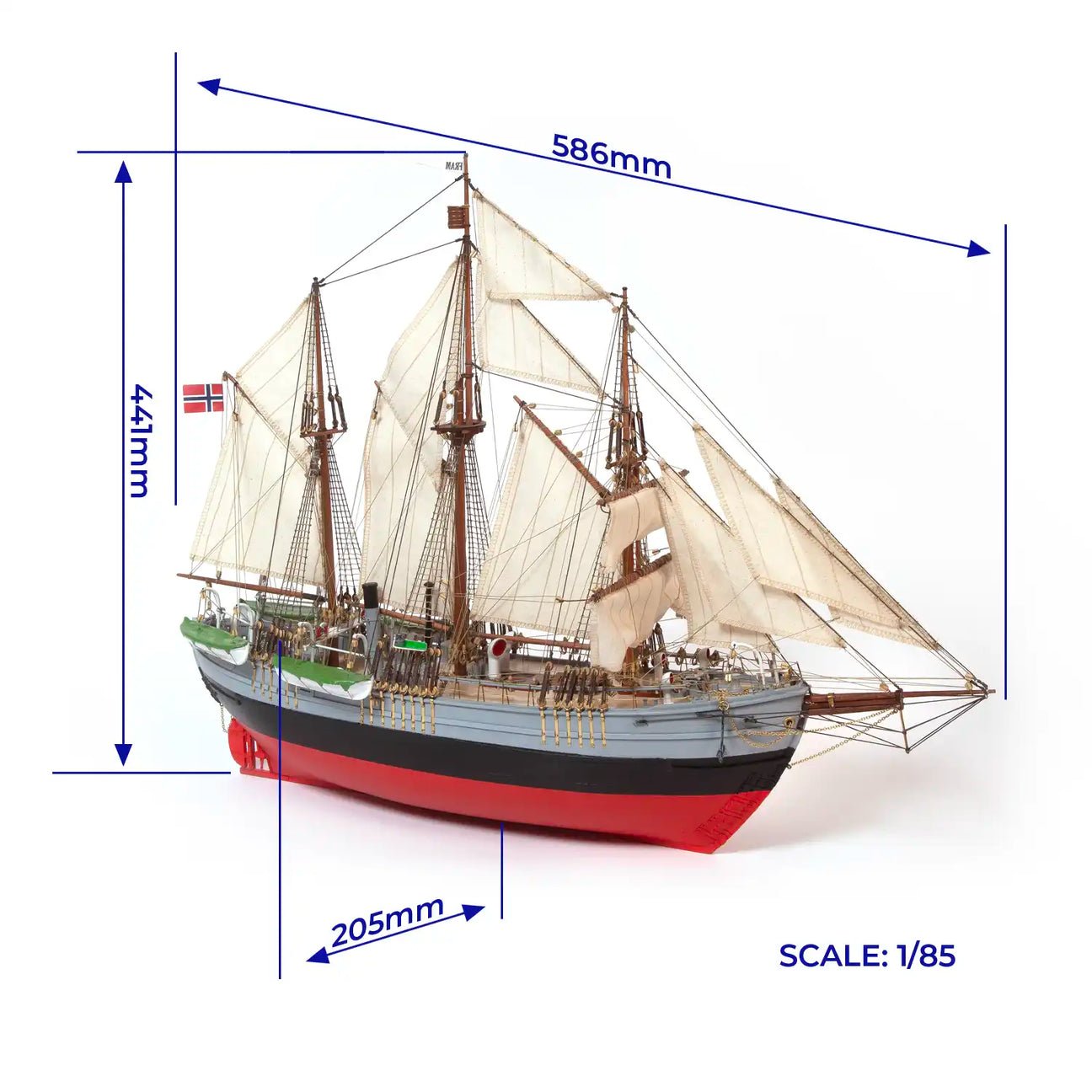
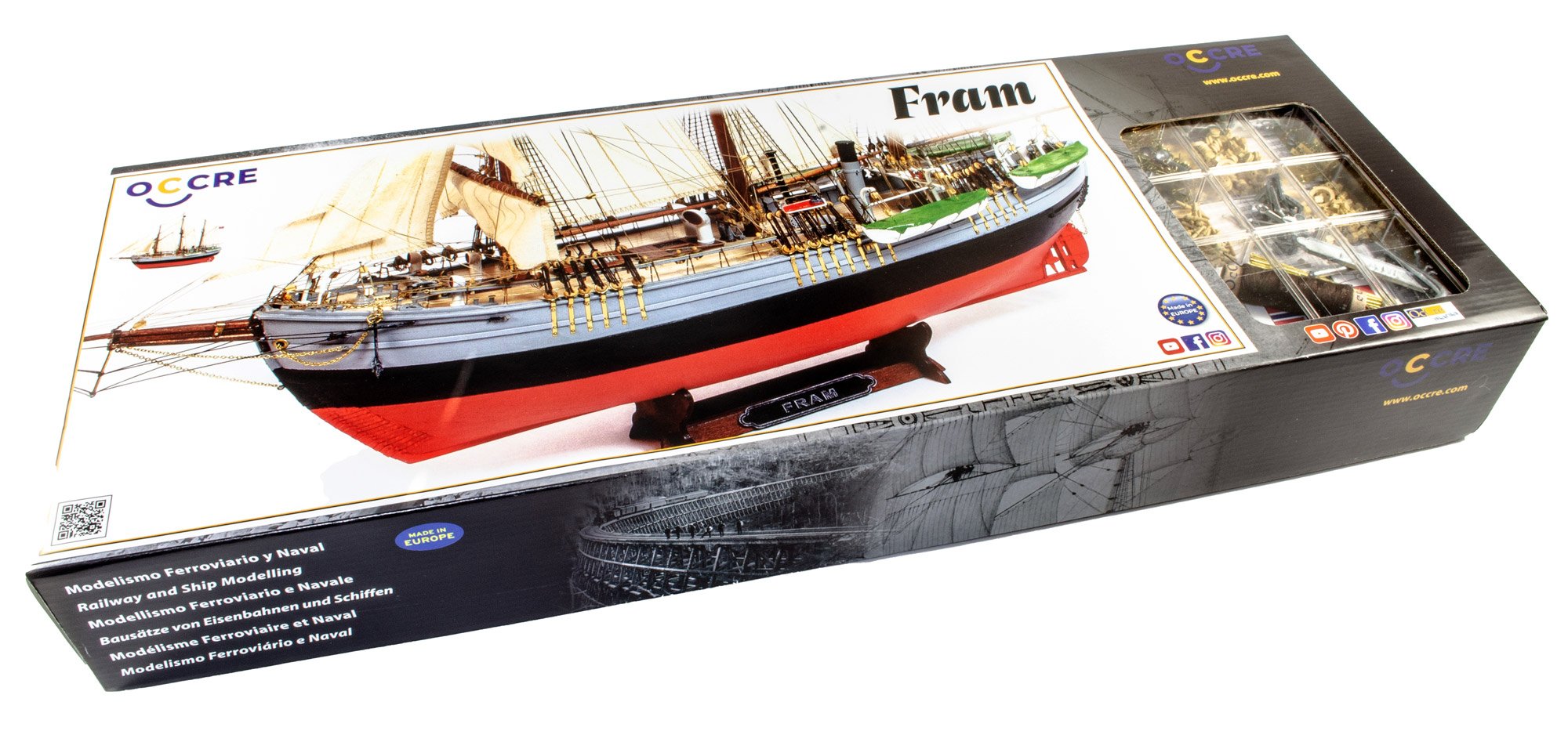
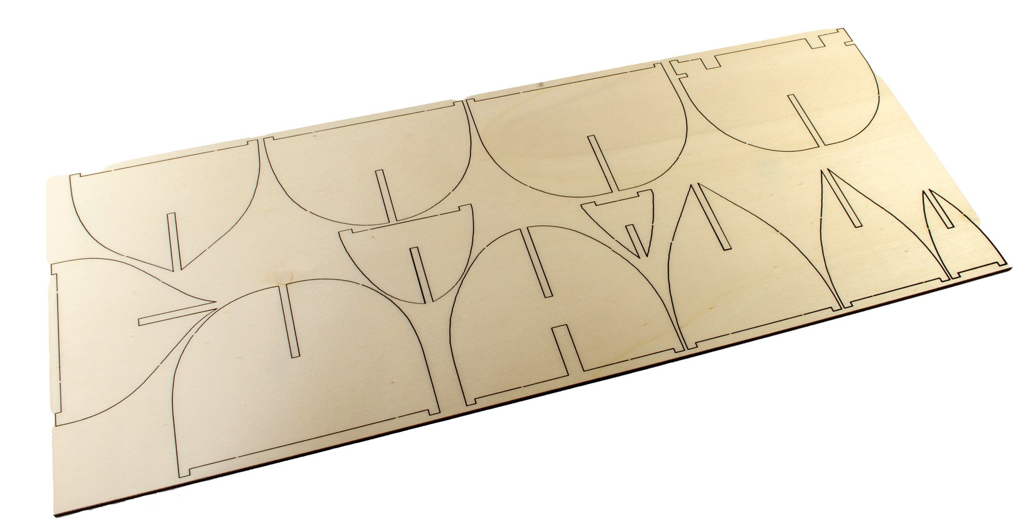
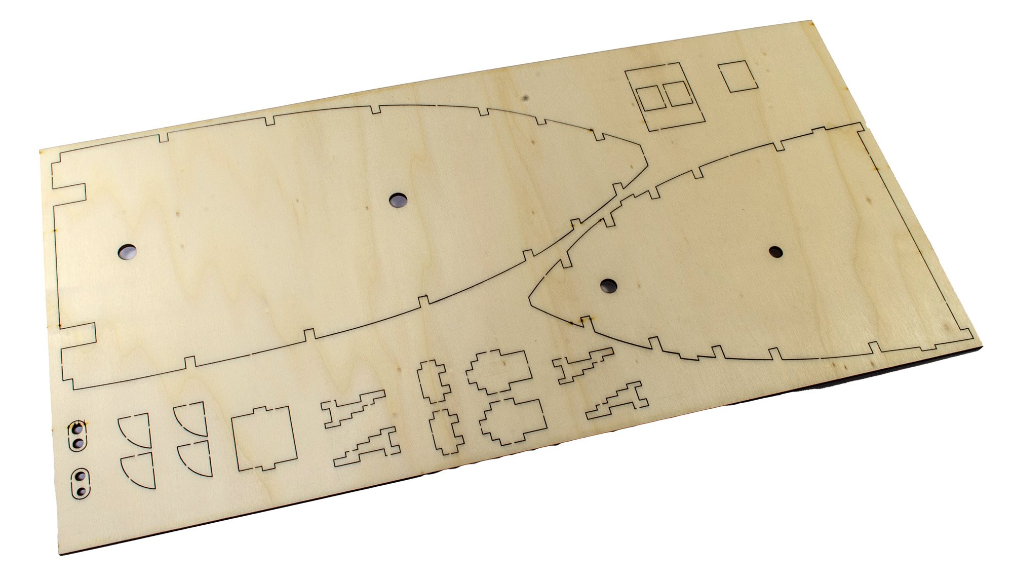
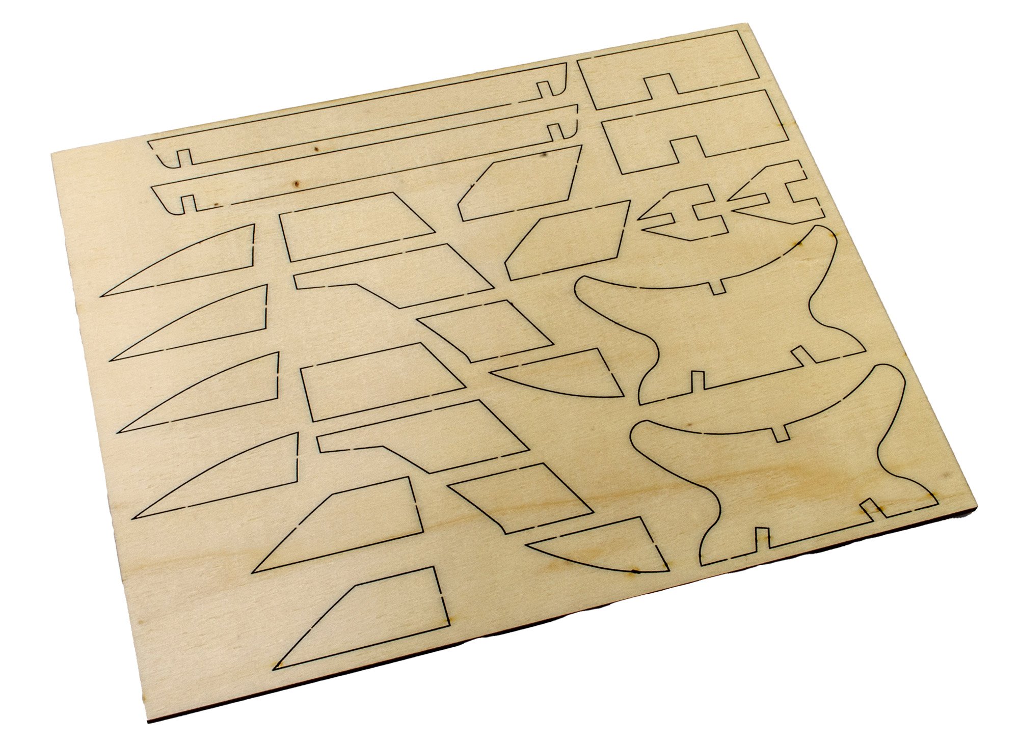
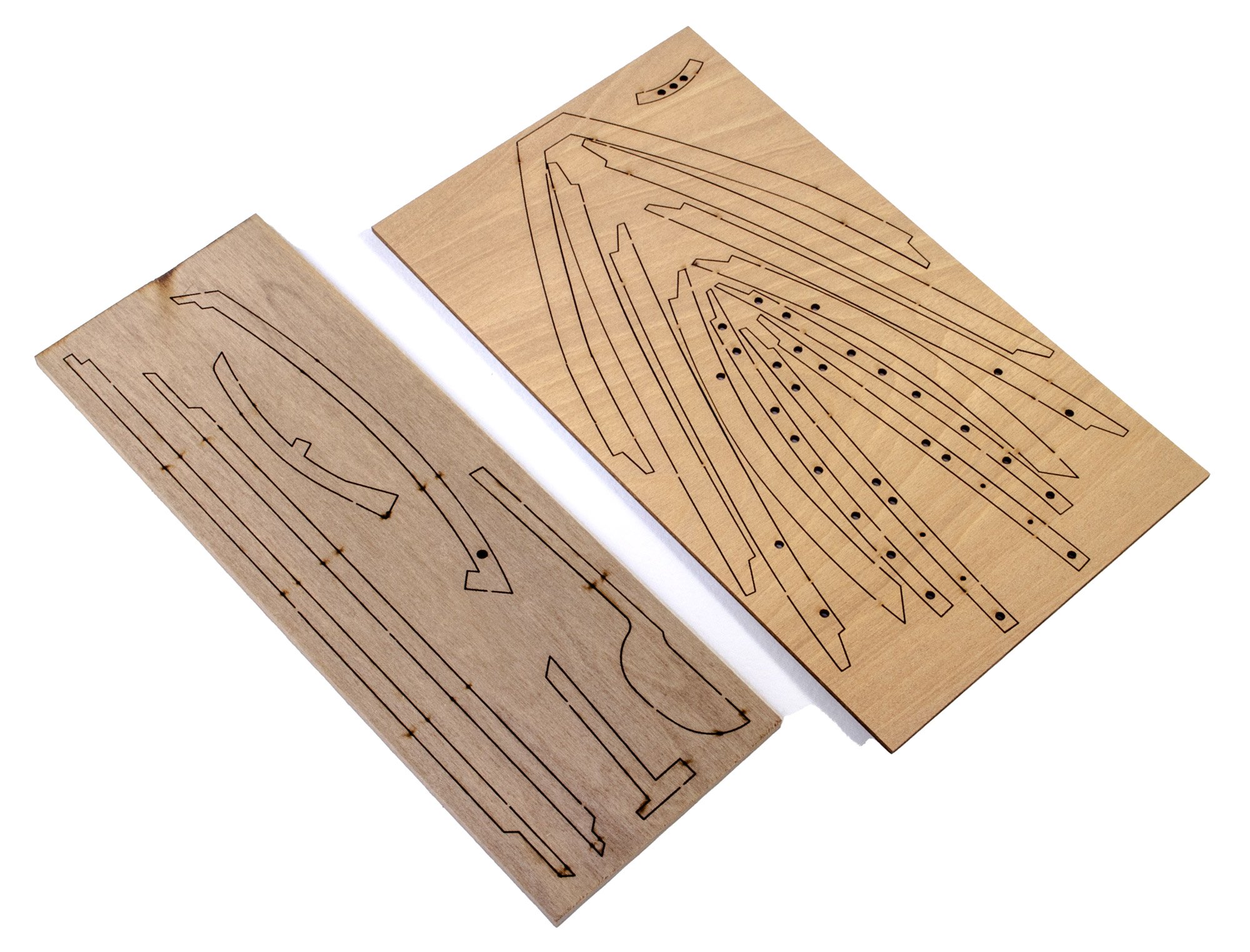
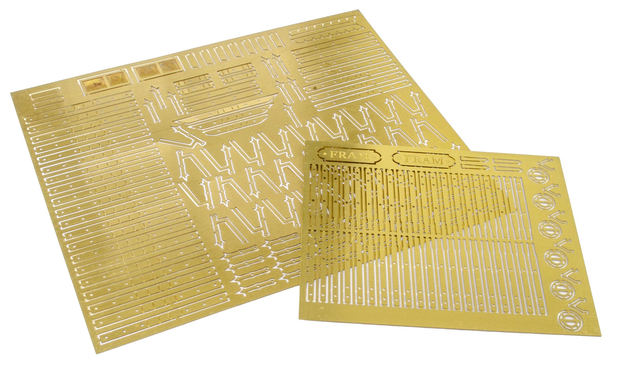
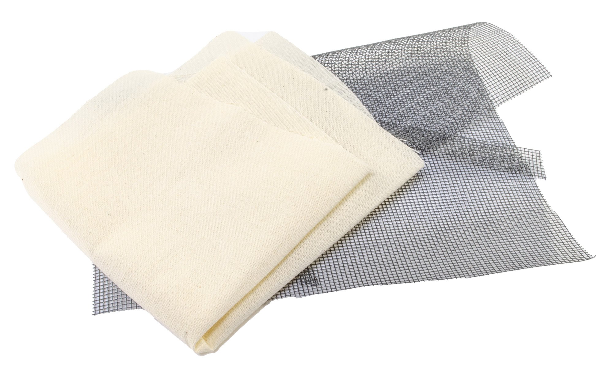
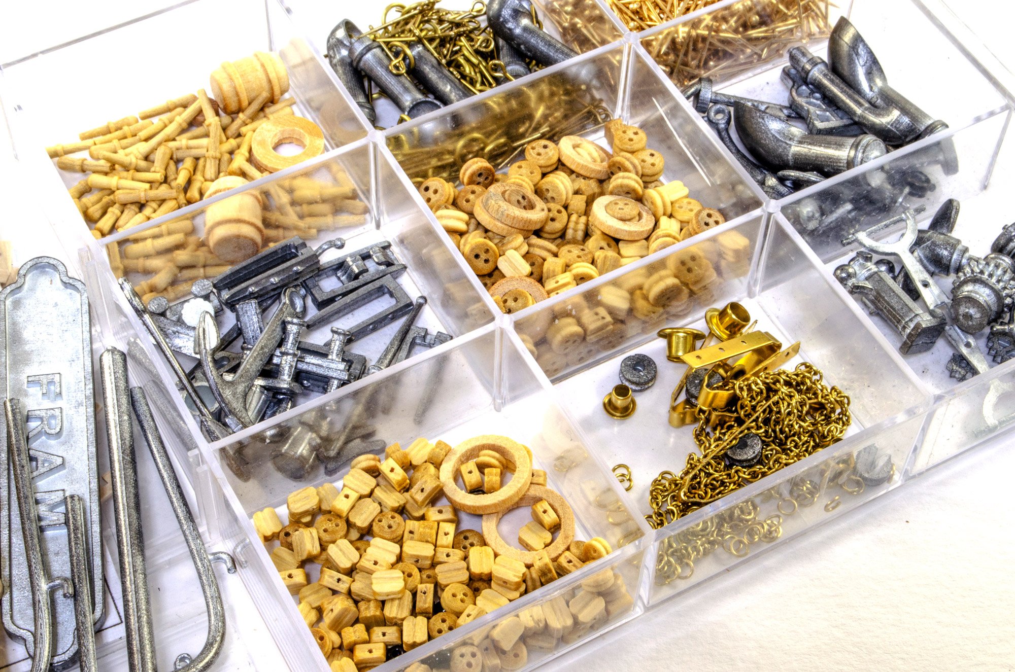
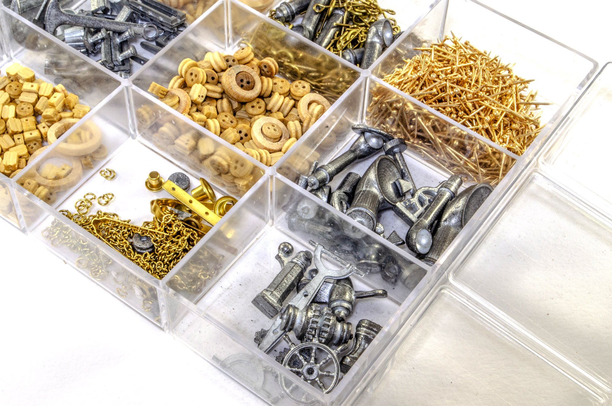
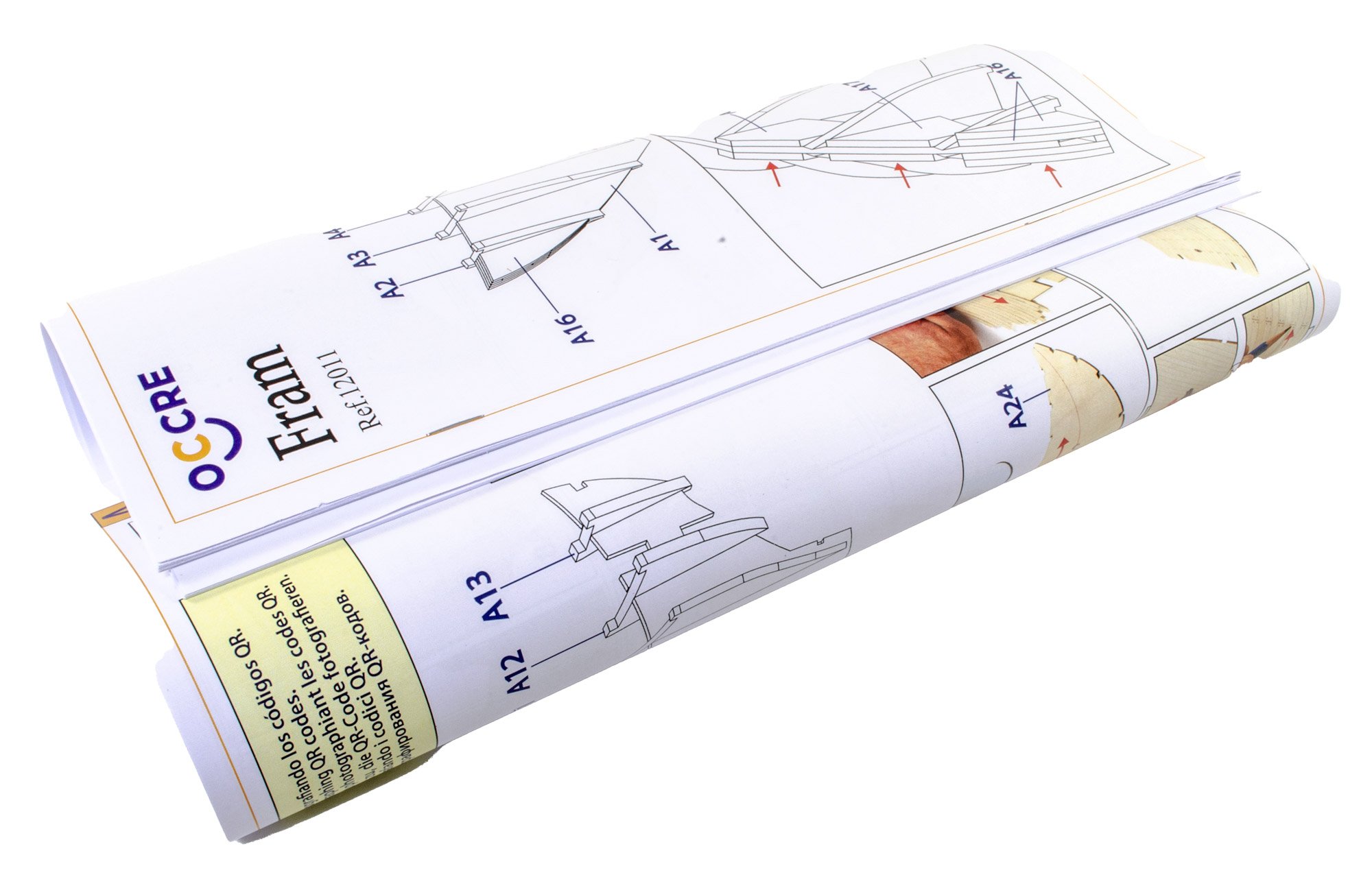
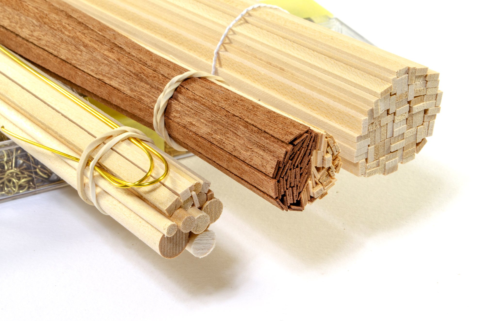
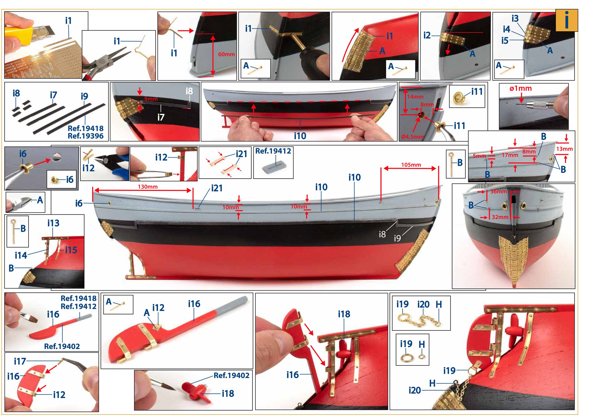
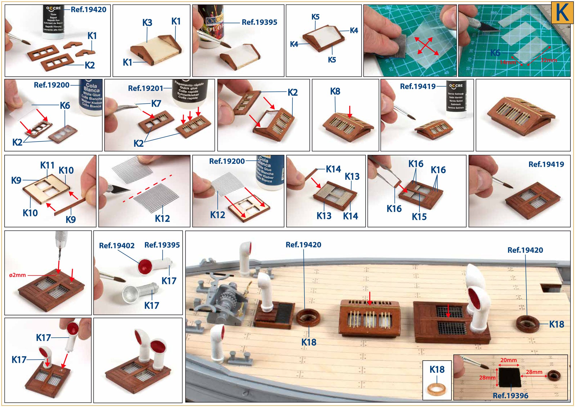
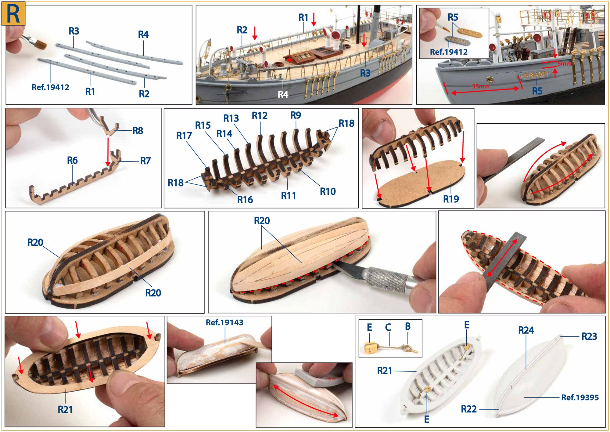
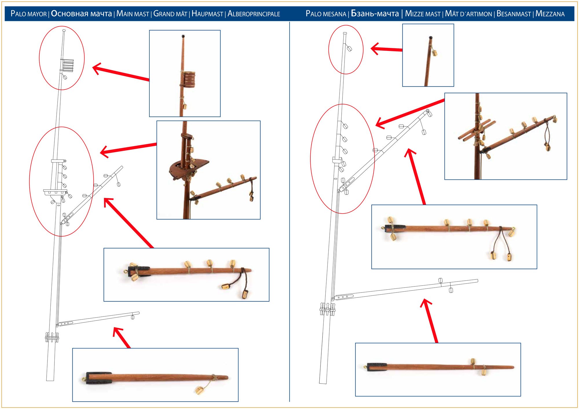
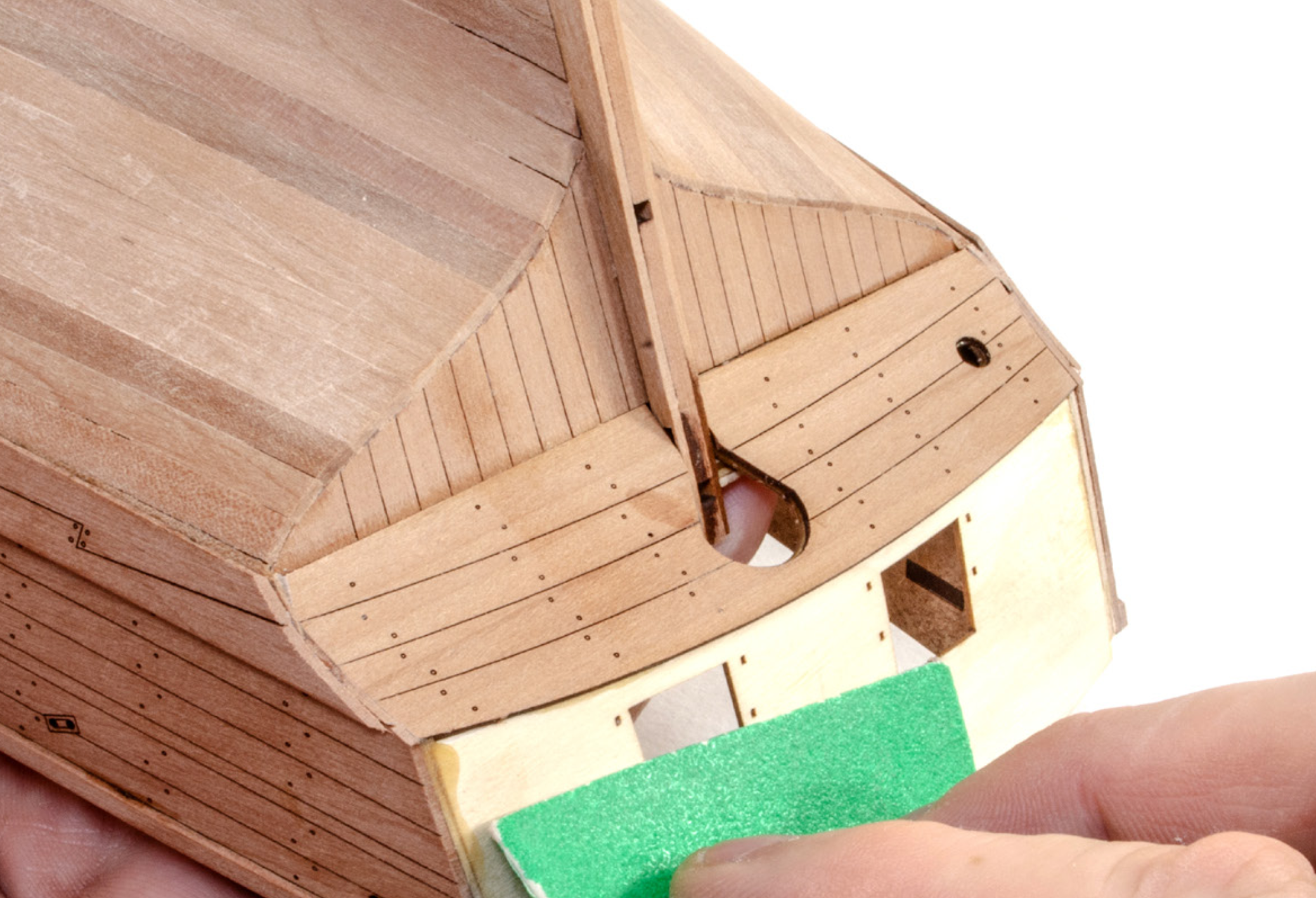
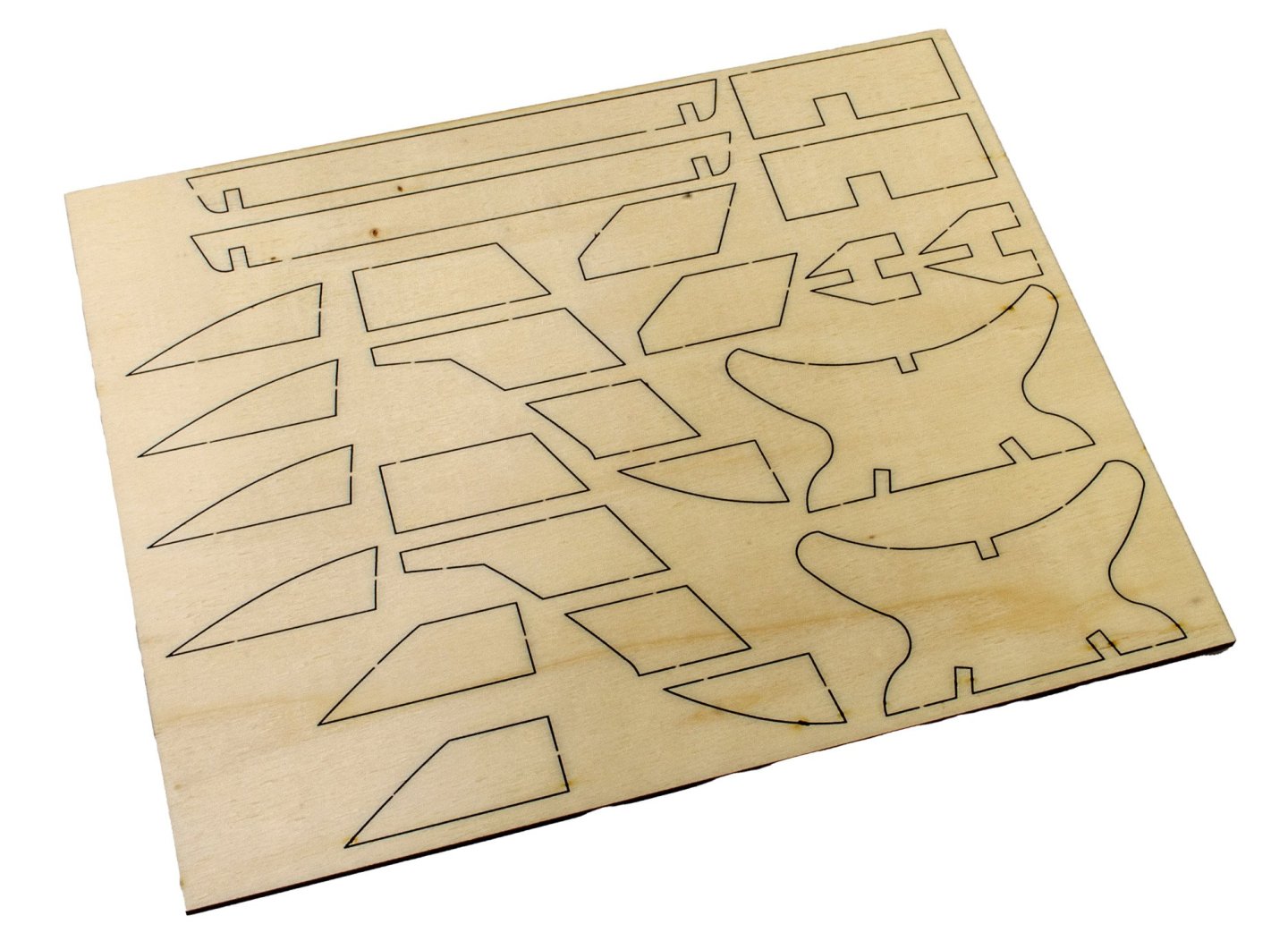
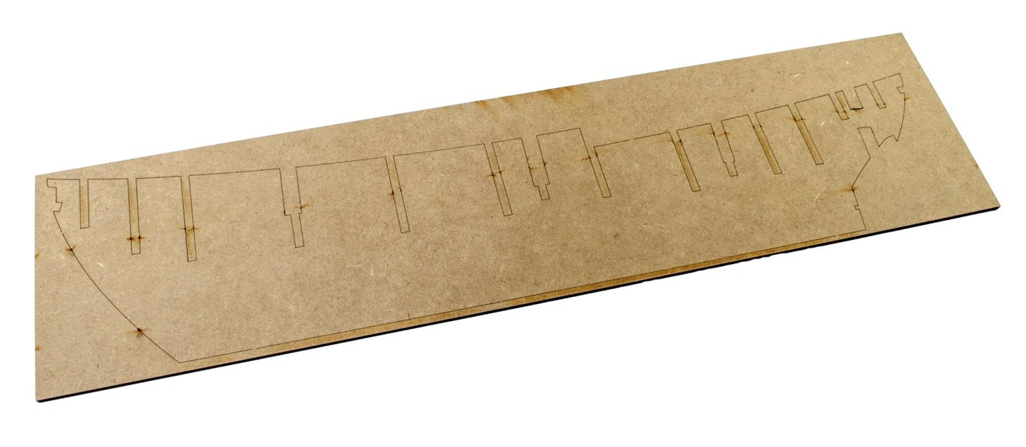
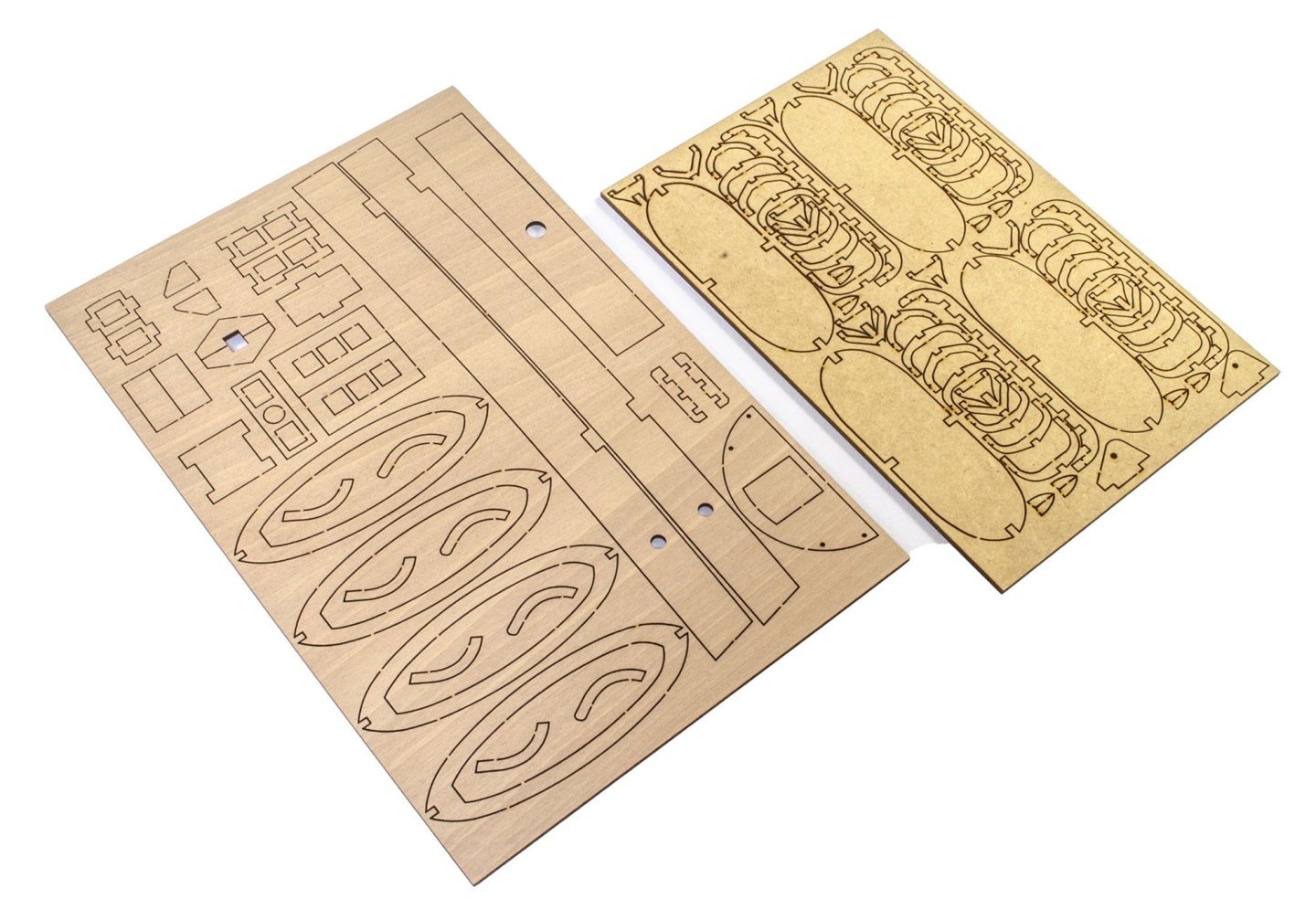
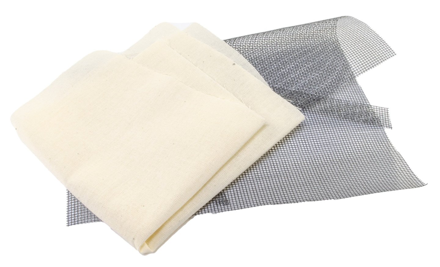
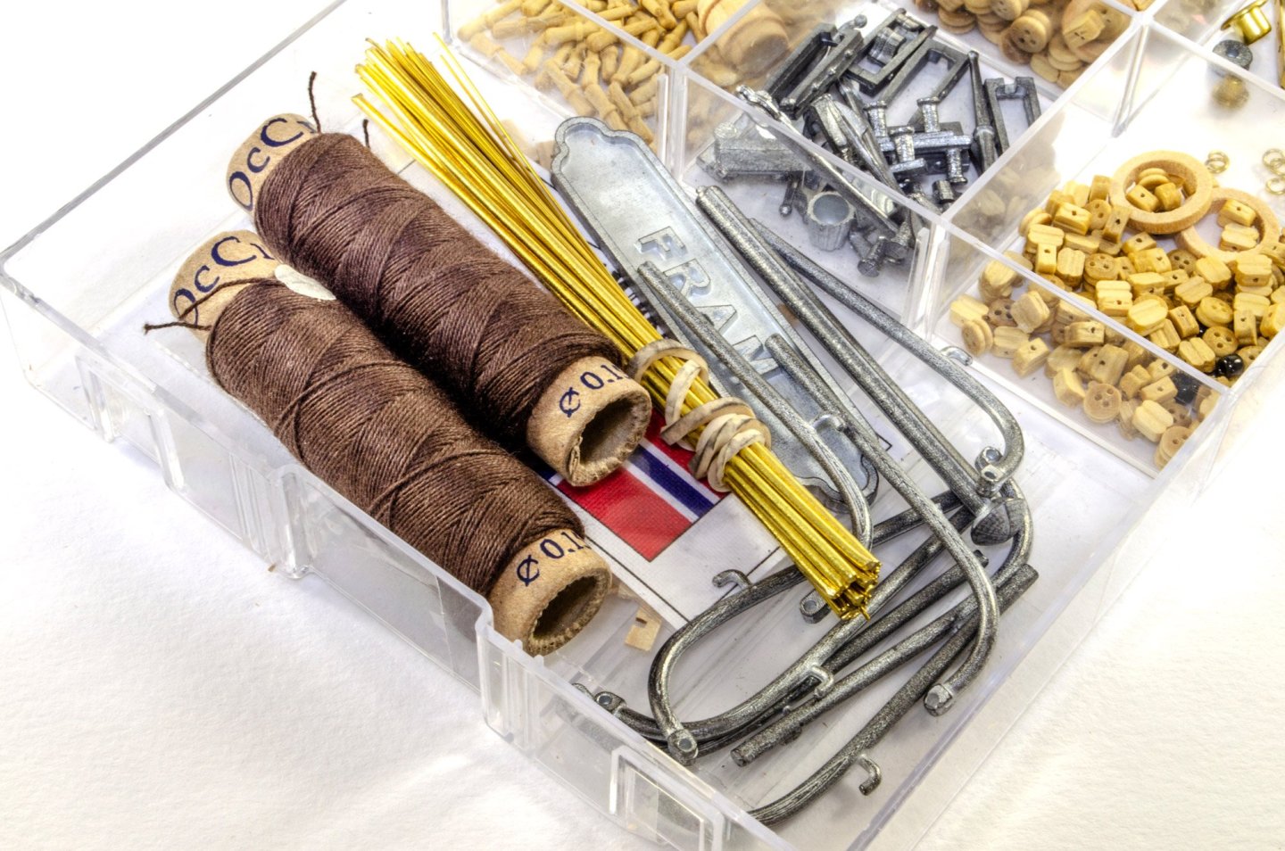
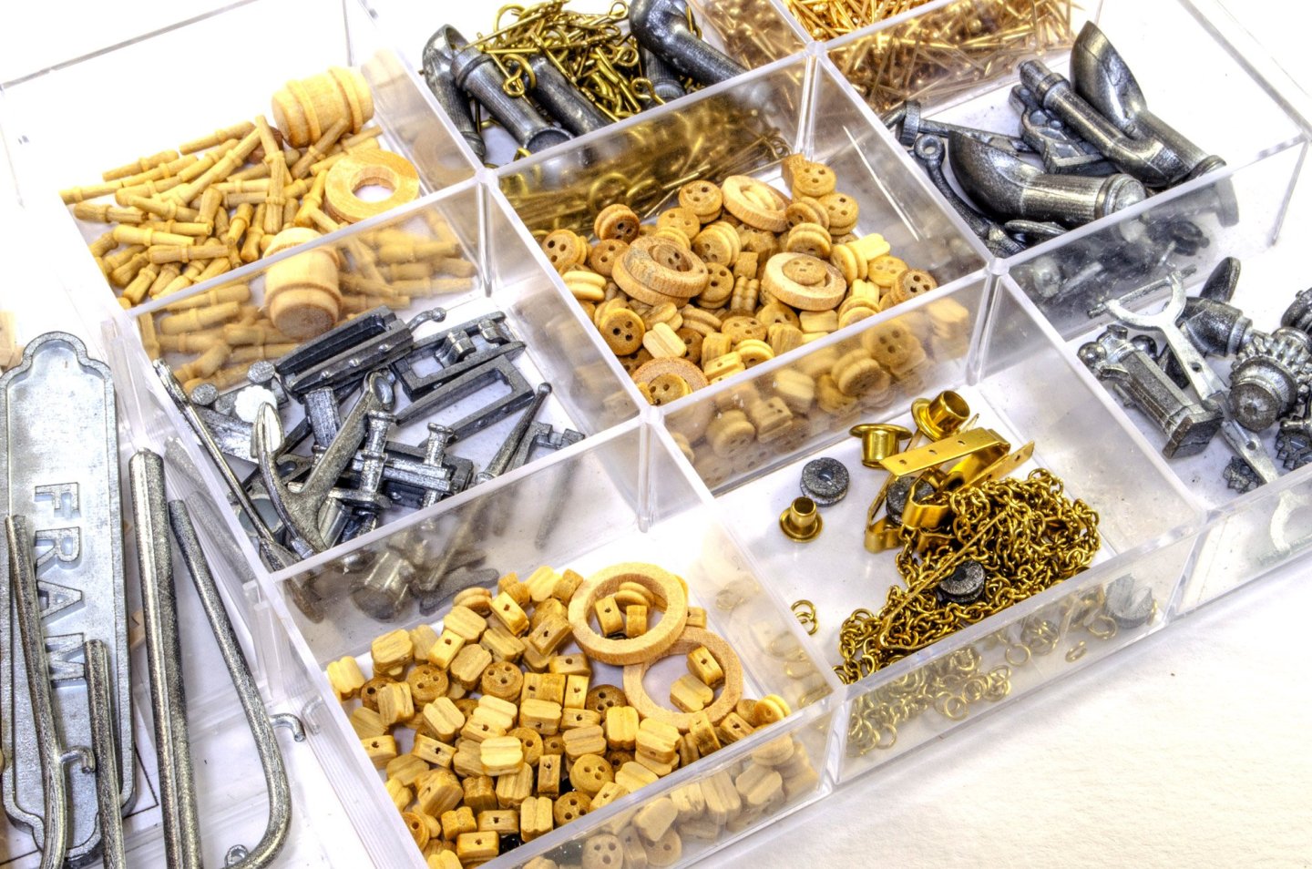
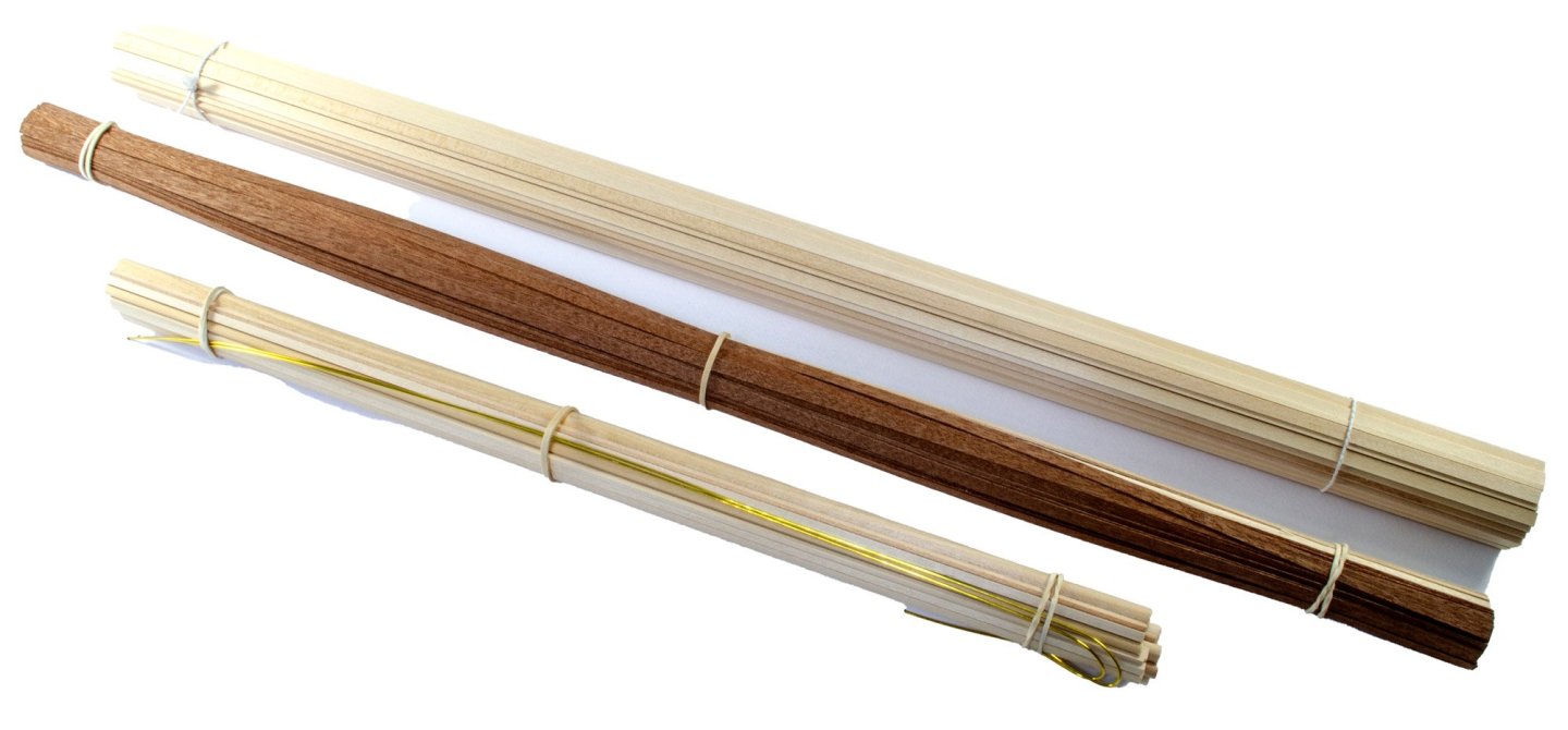
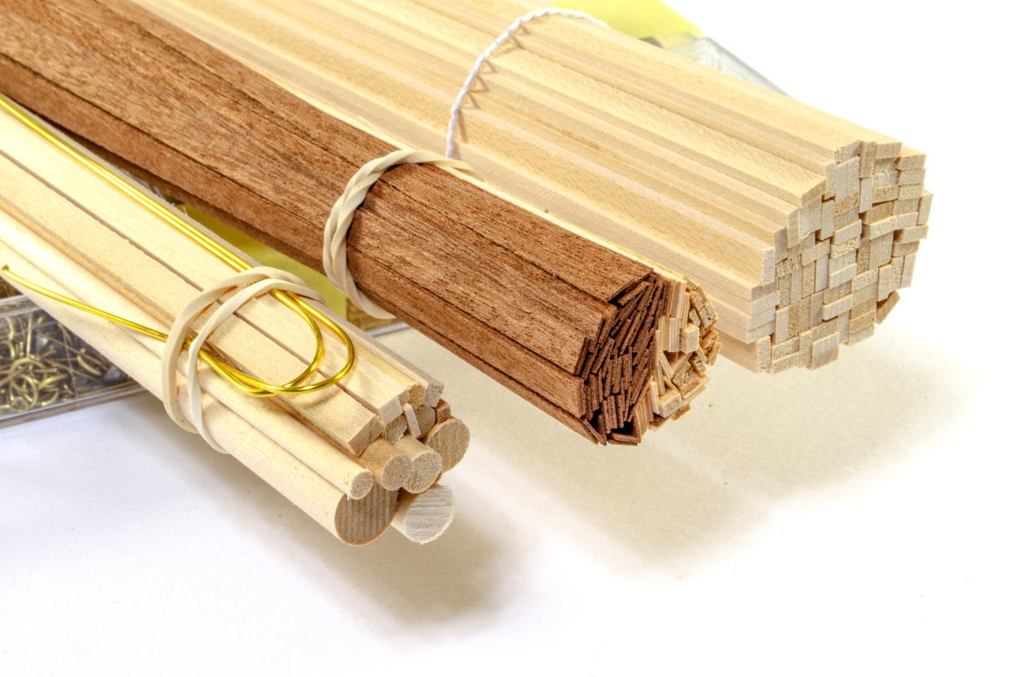
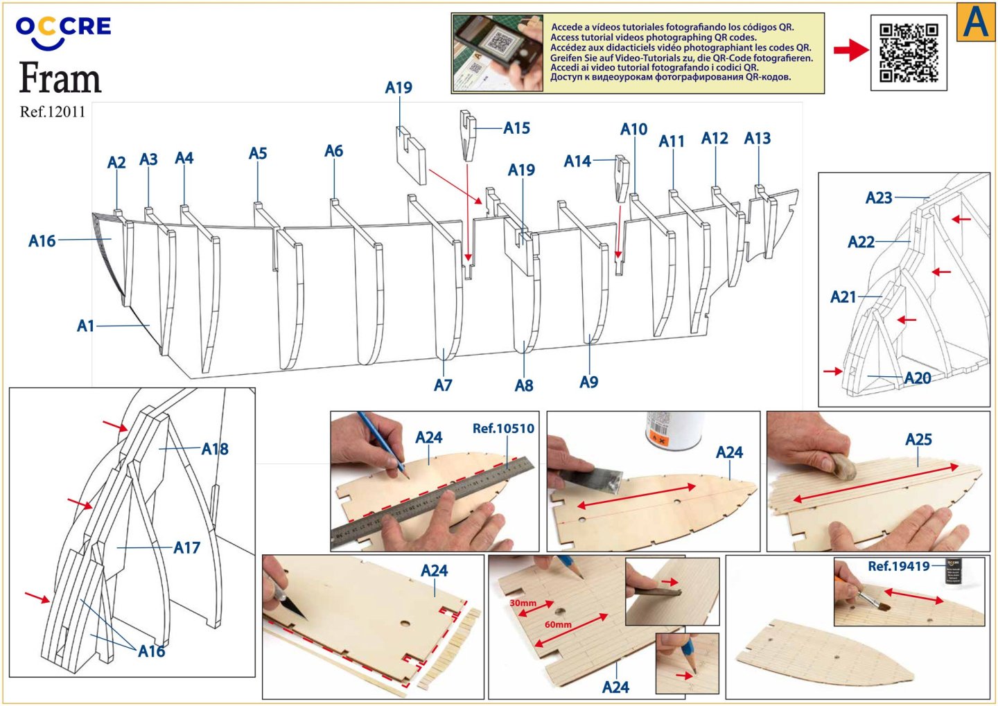
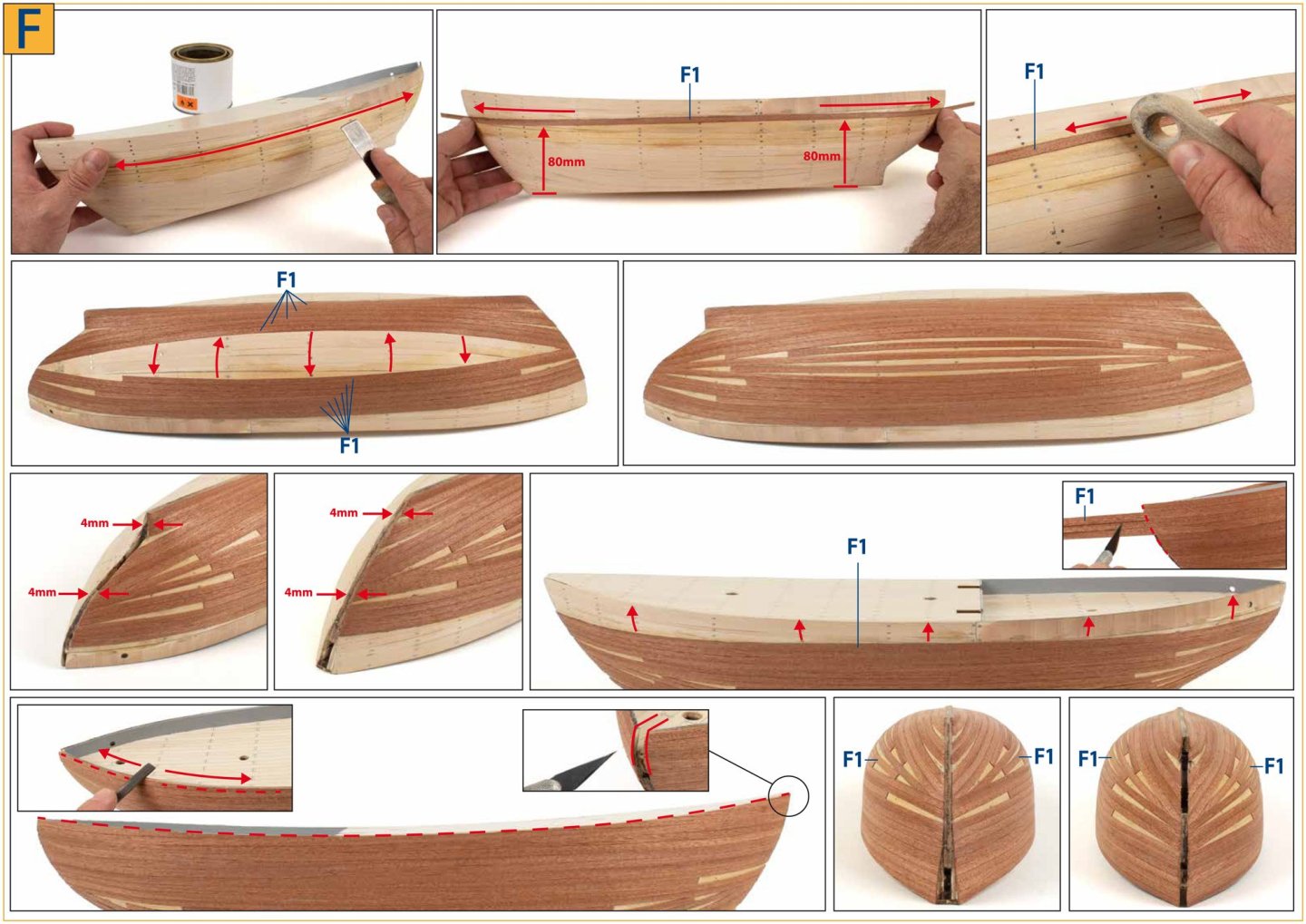
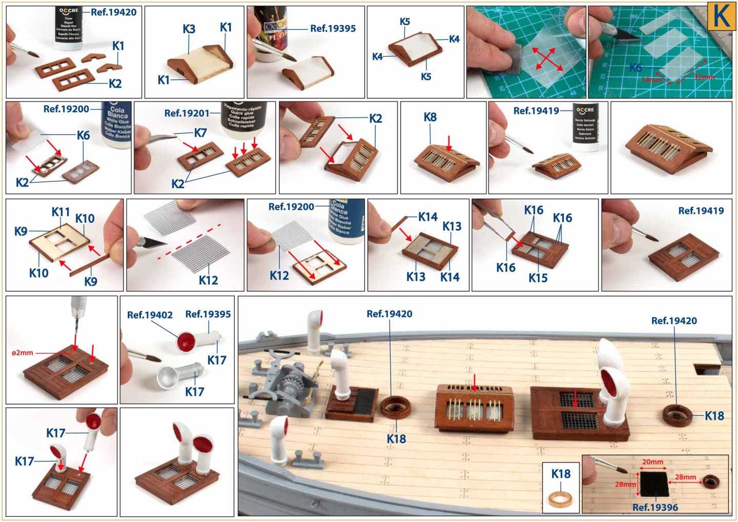
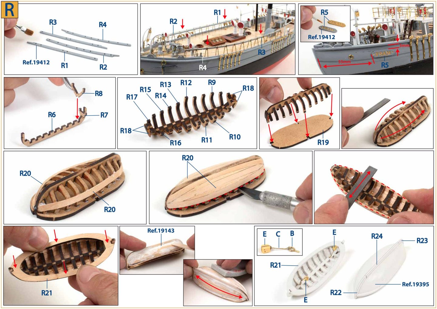
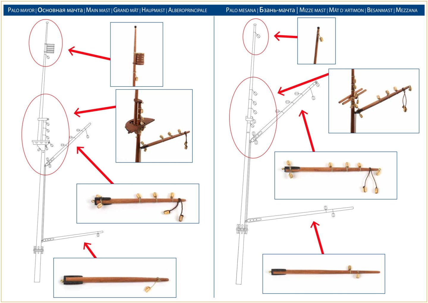
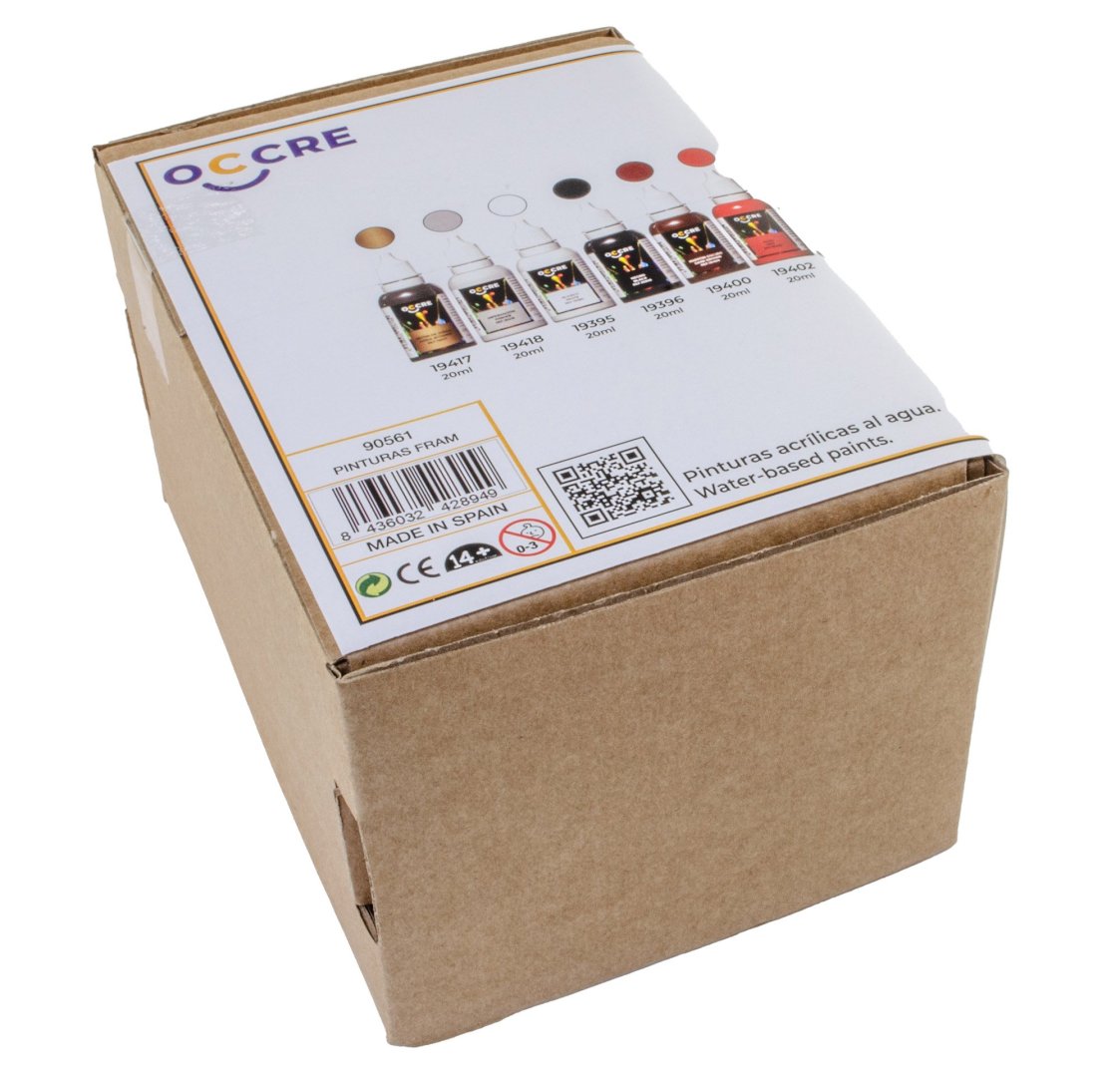
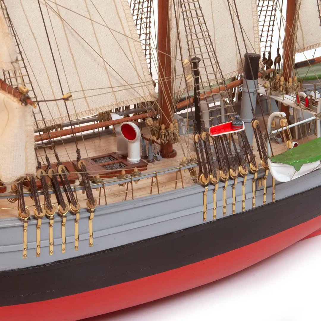
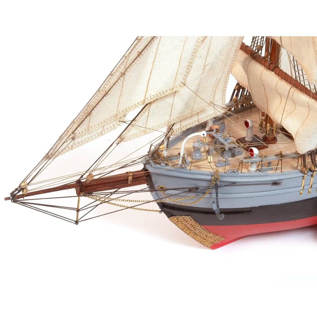
1:85 Fram OcCre Catalogue # 12011 Available from OcCre for €199,99 Fram ("Forward") is a ship that was used in expeditions of the Arctic and Antarctic regions by the Norwegian explorers Fridtjof Nansen, Otto Sverdrup, Oscar Wisting, and Roald Amundsen between 1893 and 1912. It was designed and built by the Scottish-Norwegian shipwright Colin Archer for Fridtjof Nansen's 1893 Arctic expedition in which the plan was to freeze Fram into the Arctic ice sheet and float with it over the North Pole. Today, the historic ship resides at the Fram Museum in Oslo. It is one of the most visited and renowned museums in the city. This prestigious museum is a must-see for travellers interested in polar exploration and maritime history, as it provides a unique experience combining detailed information, immersive exhibits, and the chance to closely admire the resilient vessel that once braved the Arctic and Antarctic ice fields. The Fram Museum has become a world-renowned landmark, reflecting the legacy of adventurers like Fridtjof Nansen and Roald Amundsen, whose feats helped broaden our understanding of the most remote regions of the planet. Abridged from Wiki and OcCre The kit Fram is packaged into OcCre’s medium size generic box that has an opening to see the parts tray, plus a product label secured to the top of the lid. The package is quite sturdy, which I always good for shipping. With the lid off the off, the box contents are accessed by pushing open the sides and then opening the formed card flaps which hold the various parts in place to stop them rattling about. There seems a modest number of timber parts in this, relatively speaking, but the model itself when complete builds up as below, with this image showing the size of the finished vessel. All timber materials are supplied in a shrink wrapped cellophane sheet, protecting them and stopping them rattling around in the box. Fram is constructed in the standard plywood POB style. A dozen bulkheads are laser cut into a single piece of ply. Note that there's no part numbers engraved. These are shown on the plans, so it's a good idea to write the ID on each of these key parts. The main deck is split into two to represent the split level nature of the ship. Other parts you see here are for the lower deck access door housings, poop deck stairways, etc. On this ply sheet you will find the cradle for building and displaying Fram. This will need a good priming/sealing and paint/stain to make it suitable for actual display purposes. Bow and stern filler parts are included on this sheet. Fram's false keel is supplied in a single piece on this sheet. We are now onto actual timber sheets, and here you will find keel parts and various gunwale sections. Whilst there are some deck fitting elements on this timber sheet, the rest of the parts sheet, and the accompanying ply sheet are concerned with the building of the four ship's boats, which are identical. These are constructed in very much the same way as others that you may have seen me build on my prototype work. This involves creating a framework over a base. The frames are then planked before the base is removed, leaving you with a little boat. Three bundles of strip wood are supplied, along with brass wire. The first hull planking layer is lime, followed by the darker, second layer of sapele. The wood is nicely cut and is of consistent quality throughout. All bundles are supplied with elastic ties to keep them together. If you like adding sails to your models, then there is a full suite of thirteen here, all pre-stitched and ready to fit. The colour of these is cream/off-white, so could be fitted to the model without any extra colour treatments. All sails are supplied flat, packed into an OcCre envelope. Another envelope is supplied in the package. This includes TWO brass photo-etch sheets, plastic mesh sheet for deck fittings, fabric sheet for boat tarpaulins, and eight spools of rigging cord in both dark and natural. There is a single fitting box with this kit, chock full of components in both bras and cast, along with rigging blocks, brass pins, brass wire, and more rigging cord. A printed Norwegian flag is also included. All rigging blocks and other machined wooden parts, such as barrels, are also found in this component box. Fram is bundled with a set of paper instructions, totalling 44 sides of colour-printed sheets which show Fram being built in a series of photographs. Included in the sheets is a parts list, parts map, rigging drawings, and plans. If you like to watch build videos, then this is also covered by OcCre. Click THIS link to access the Fram videos on their YouTube channel. https://youtu.be/UmquIiY-UjE?si=g4mQPVGyqvv-eTJp Conclusion OcCre have certainly been surprising the modelling community with their recent releases, and this was one that we didn't see coming until it was almost upon us. From a builder's perspective, I would say this was aimed at the advanced beginner/intermediate modeller, and to that end, this should serve its purpose perfectly, with plenty of detail throughout, including all of those sails, should you wish to add them. My sincere thanks to OcCre for sending out this kit for review/build on MSW. To purchase directly, click the link at the top of this article. WAIT!!!! That's not quite it. We have also been sent the paint set for this kit. This can be bought from OcCre for €29,99 via THIS link. This set contains the following: Sapele wood dye Satin varnish Grey Light green Red Dark brown Black White Judea bitumen Primer Paints and primer are supposed to be 20ml, although my grey and white bottles are larger in size. The varnish and dye are 50ml. These also appear to be acrylic, and I'm not sure whether any of these can be passed through an airbrush. You would need to dilute, possibly with distilled water, and test them first. For now, here are some completed images of Fram...


-
Unfortunately, that is the case. There are very few settings in the Gallery app, and it would need either a 3rd party plugin (not available) or a code customisation. We would also like to set it so members HAVE to create an album to add their images to, but that option isn't available either.
-
Those inner walls look great in that colour. As for that metalwork on the carronades, I think I've probably even fitted them a different way on other models I've built!
- 241 replies
-
- 1
-

-
- Vanguarrd Models
- Harpy
- (and 1 more)
-
Just a reminder that the video instructions for this are continually being uploaded to Artesania's YouTube playlist. They are currently at video #42. Check it out here: https://www.youtube.com/watch?v=Y6VAfr_M2jg&list=PLSWjc49gHdjlmgxz-loTM9MorsDryYgHO
-
There's Sphinx too. https://vanguardmodels.co.uk/product/hms-sphinx-1775/

-
There you go: https://vanguardmodels.co.uk/product/hms-indefatigable-1794/ There's a build log in my signature, and other build logs here on MSW.
-
I'm not generally a fan of video. I used some in the engine builds as that's the only way you can gauge the result. For static models, not so much.
-
Scrappee Liaison by chadwijm6 - Microaces - RADIO
James H replied to chadwijm6's topic in Non-ship/categorised builds
How did this go? -
Looking great, and that transition looks fine too.
-
I used that stuff all the time when I was building flying models. You needed good, er, ventilation.
- 332 replies
-
- 1
-

-
- Harpy
- Vanguard Models
- (and 1 more)
-
On the prototype, this was done as with the other ships. The was sanded flush to the lime, then the second layer sits atop that.

- 332 replies
-
- 6
-
-
- Harpy
- Vanguard Models
- (and 1 more)
-
Ok, this is now fixed. For some reason, the option to allow all file types, was set to 'none'. This isn't something that's been tinkered with, nor has there been any update, so it remains a mystery.

-
You have logged in to post that message.
-
Chaps, the password info is very good advice, but please can we keep this one on topic as it's extremely important.
-
Yes, sometime in the not to distant future. I can't say when as I don't know the date of the final release of V5. This topic is merely a heads up that it will happen, given with plenty of notice.
-
Not a problem. It did make me check though!
-
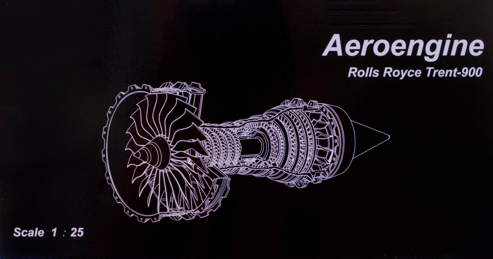
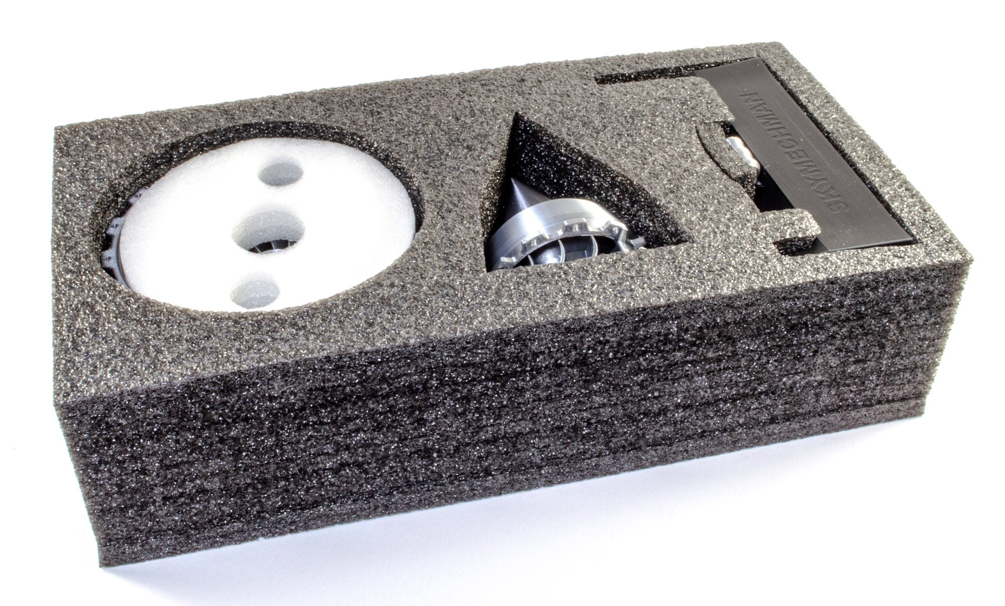
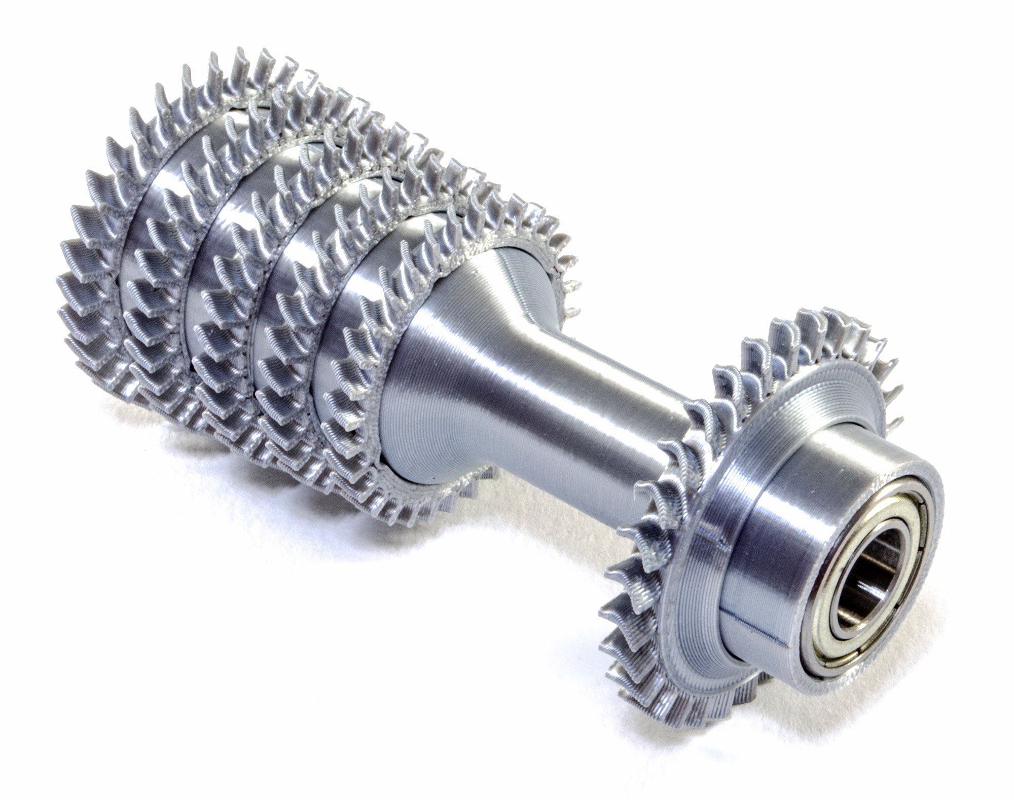
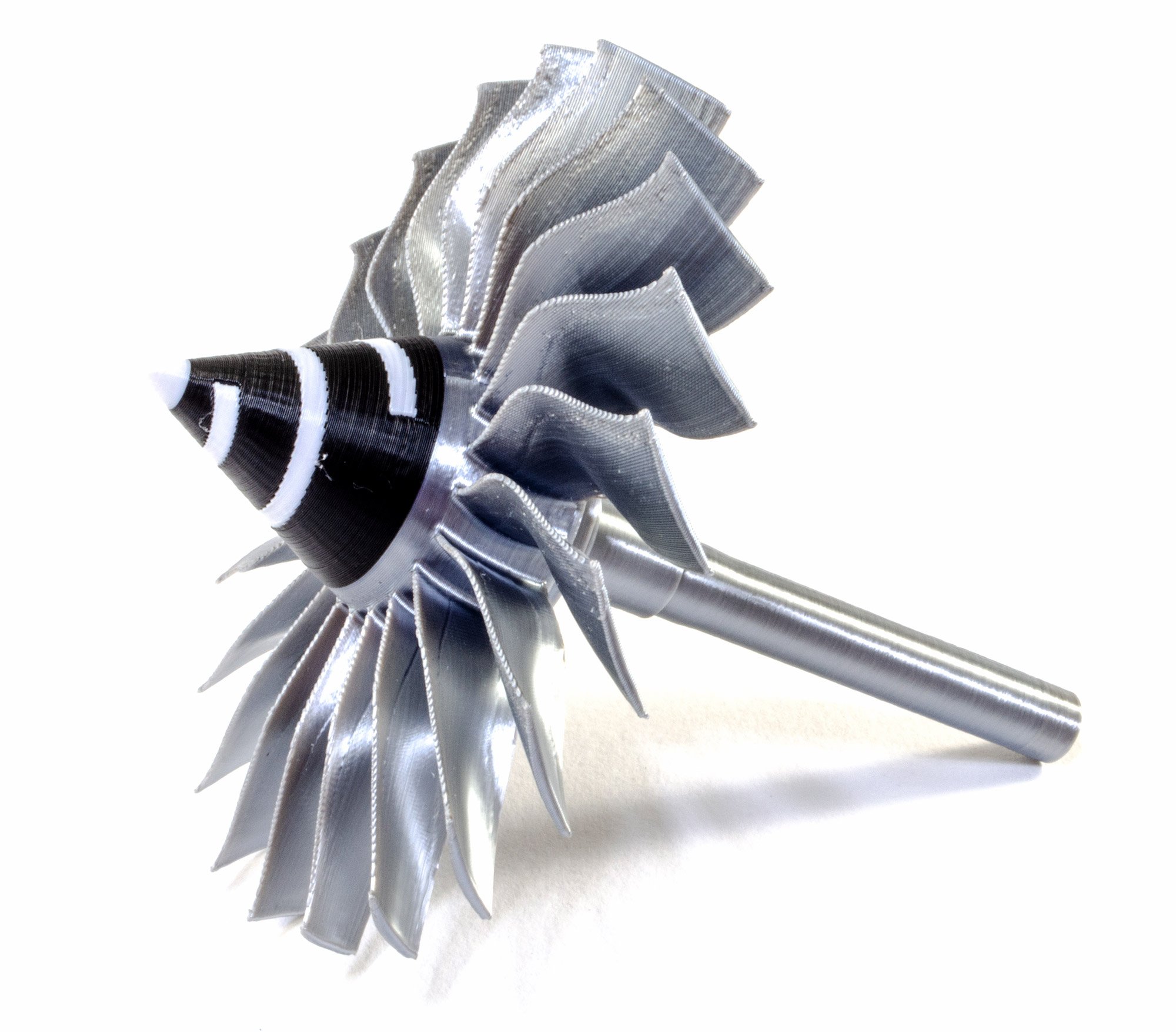
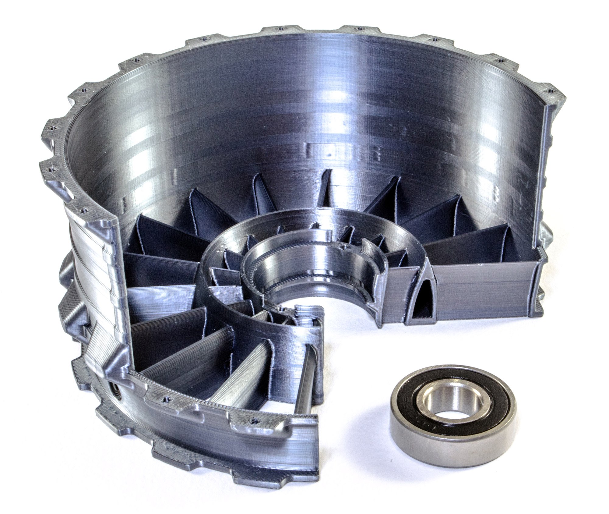
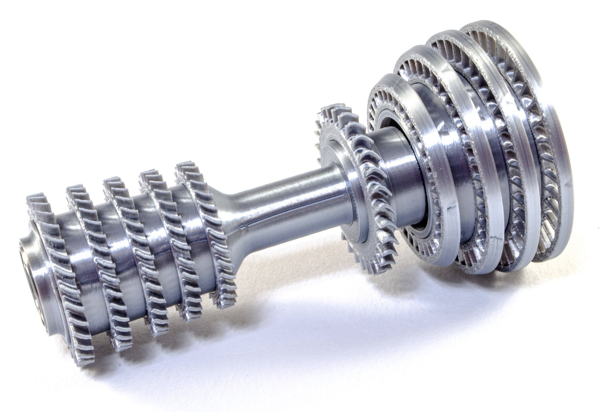
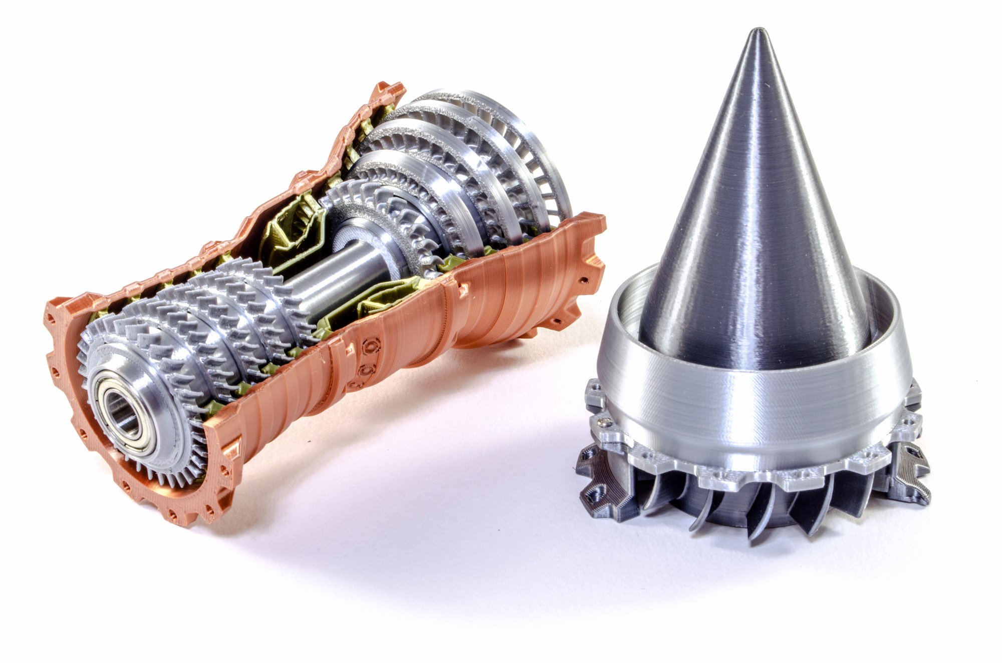
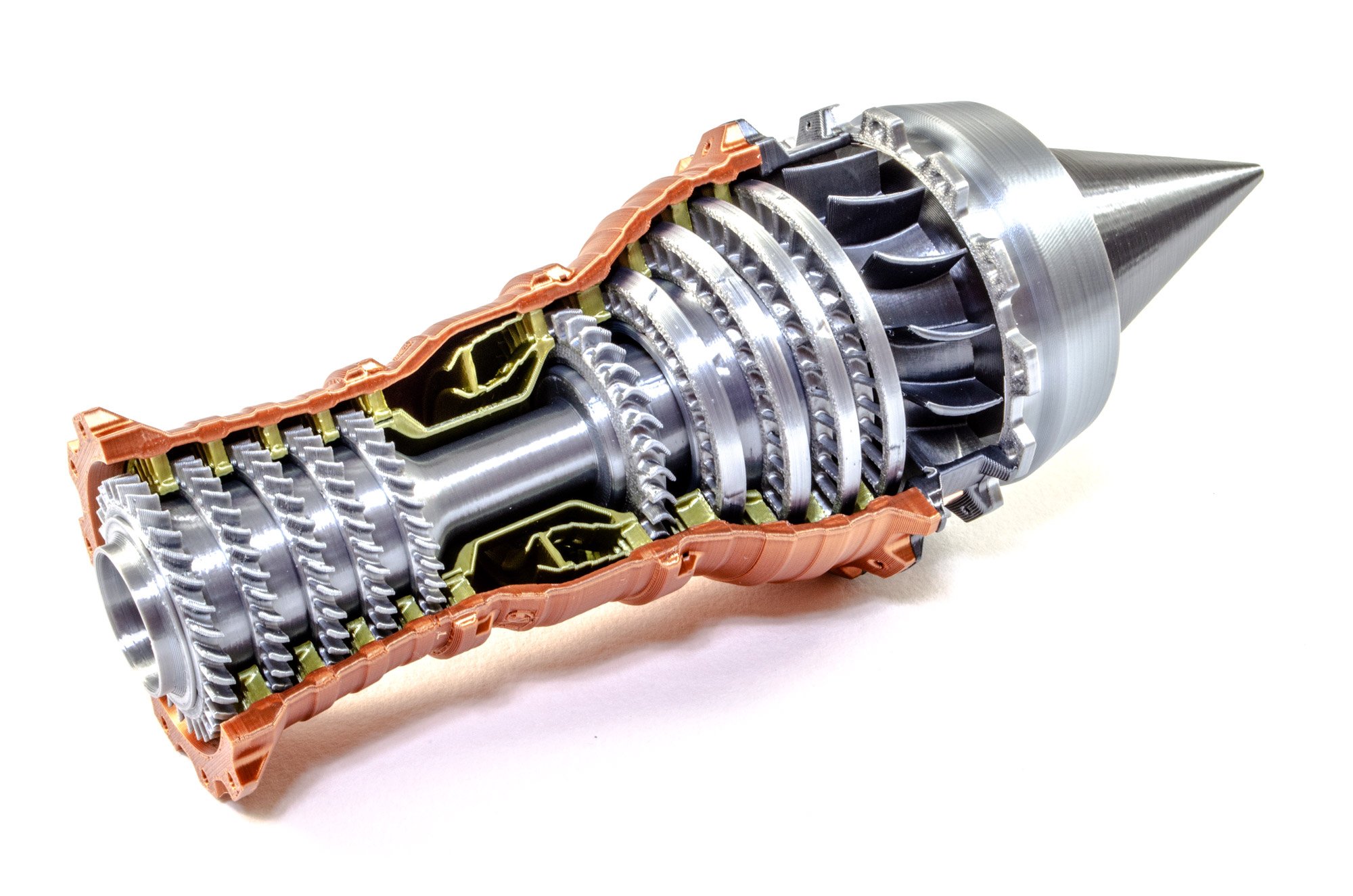
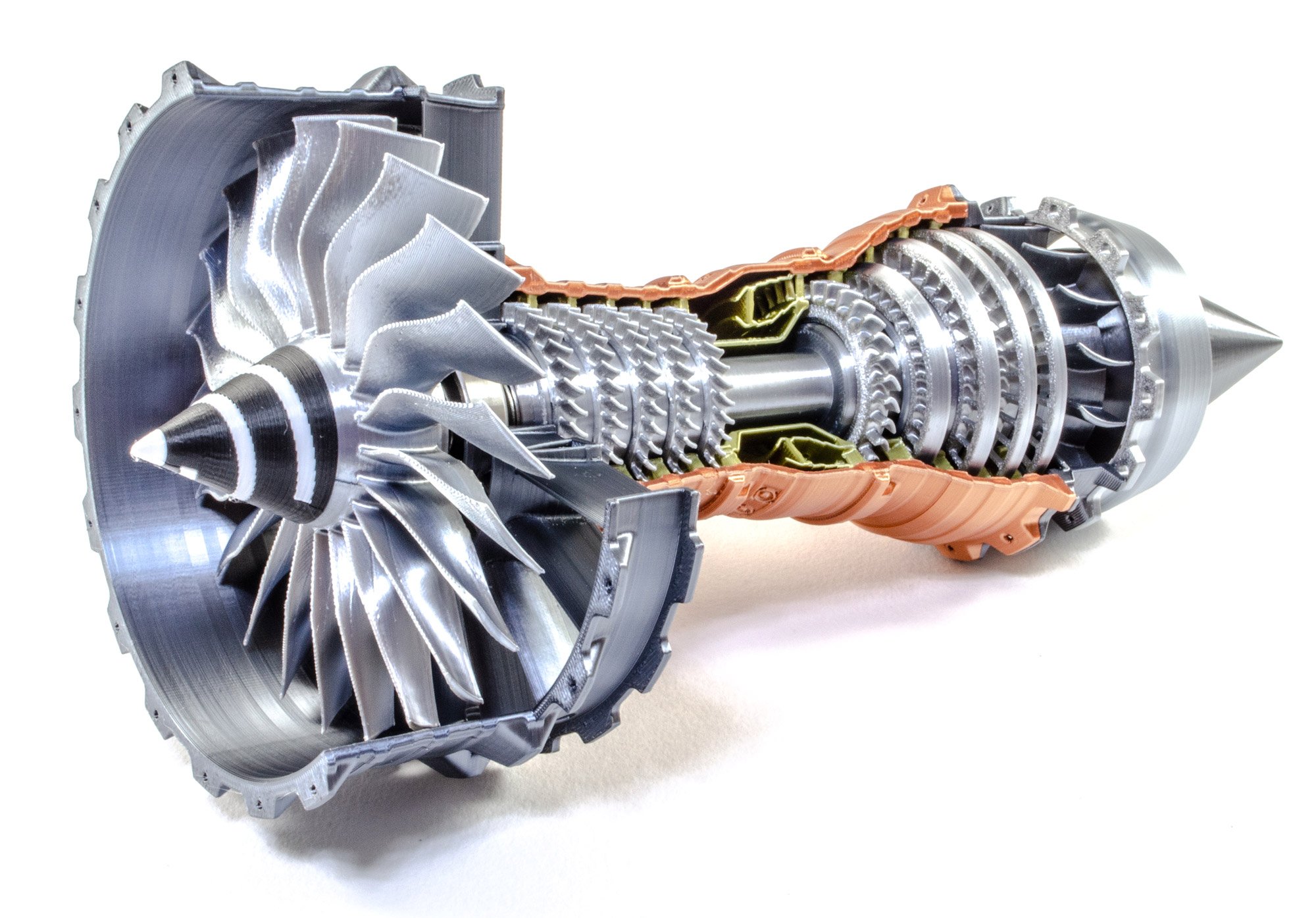
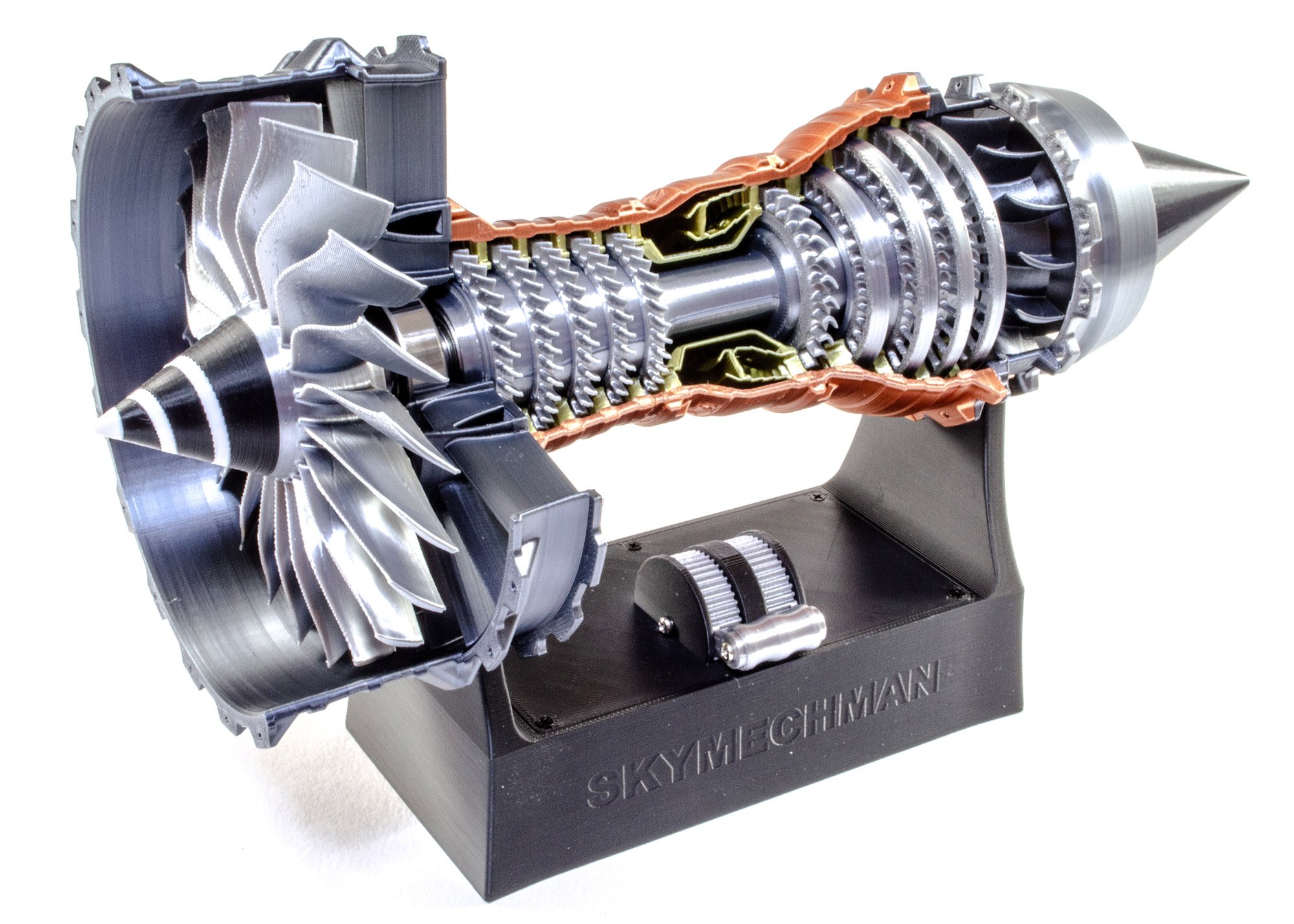
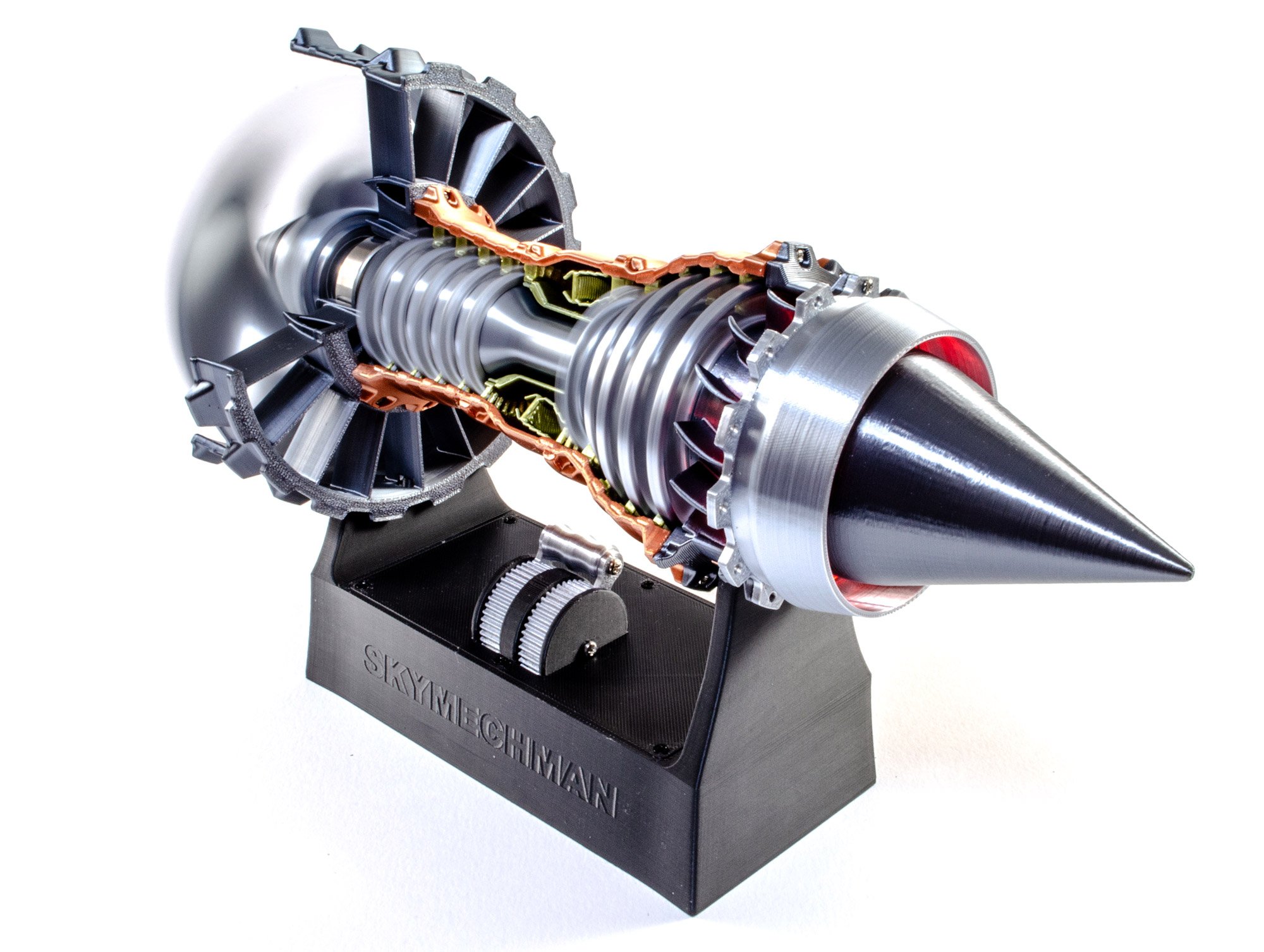
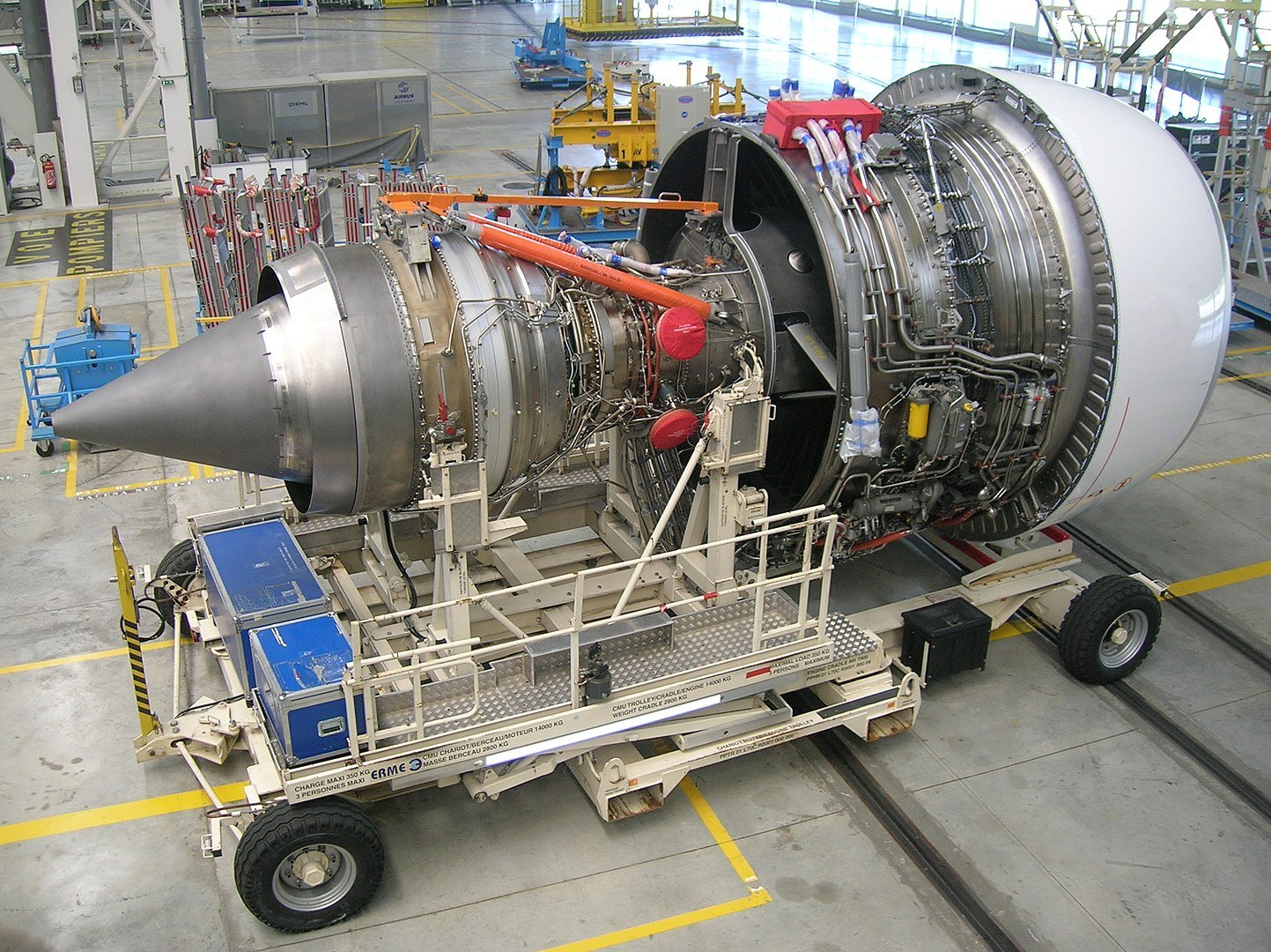
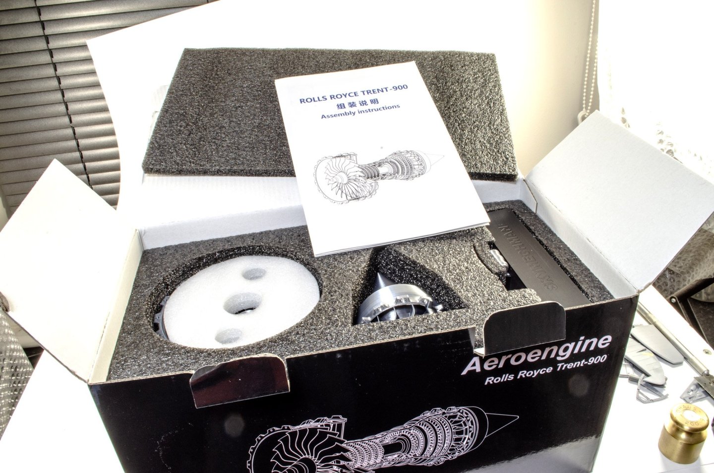
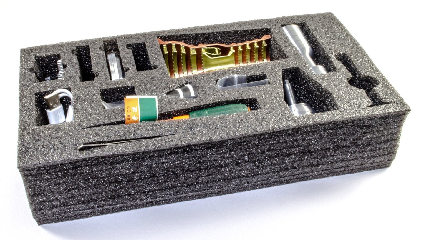
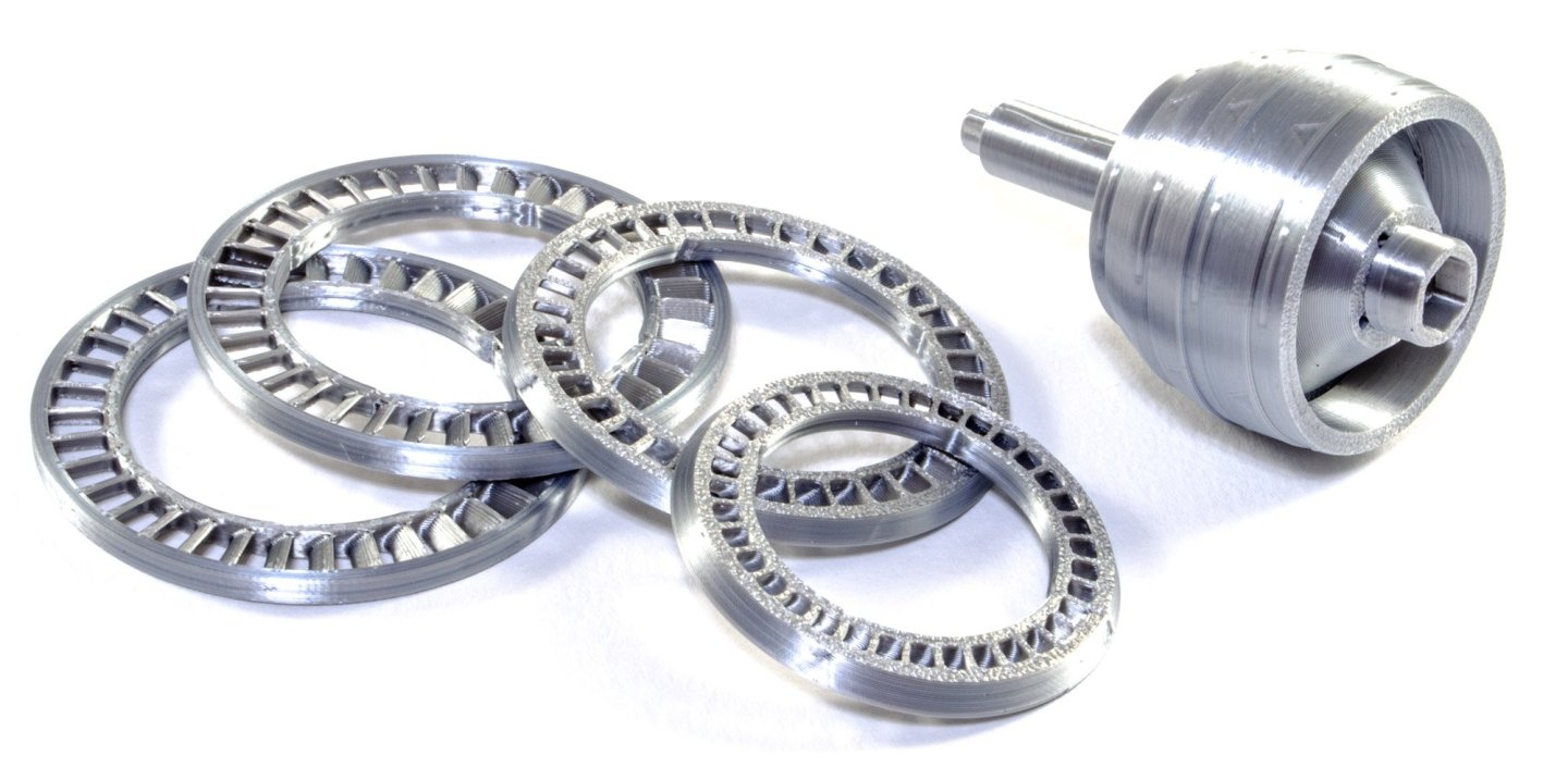
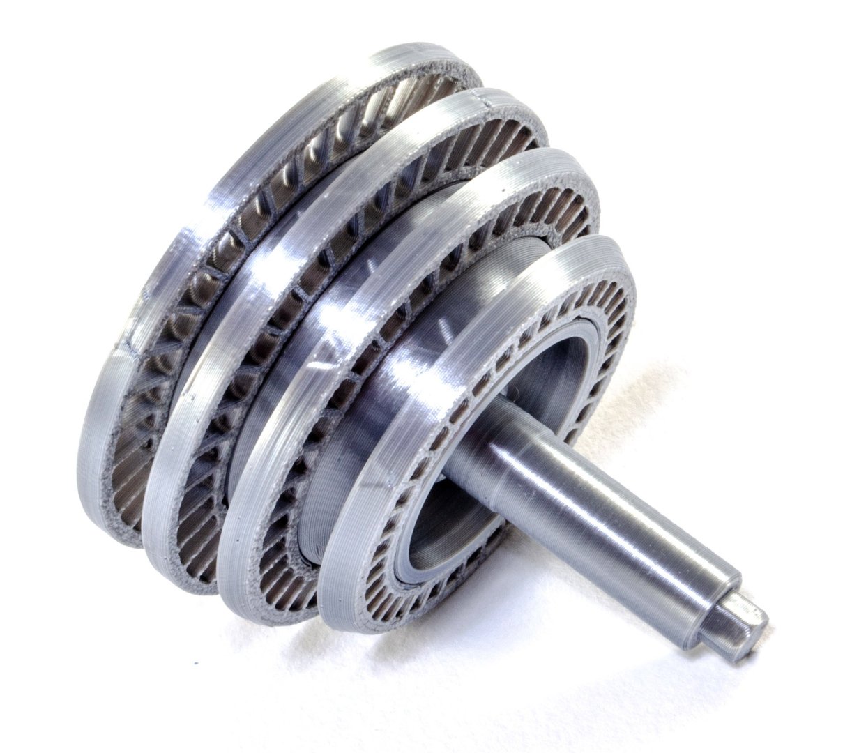
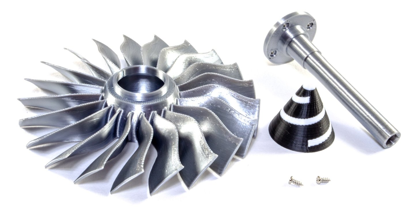
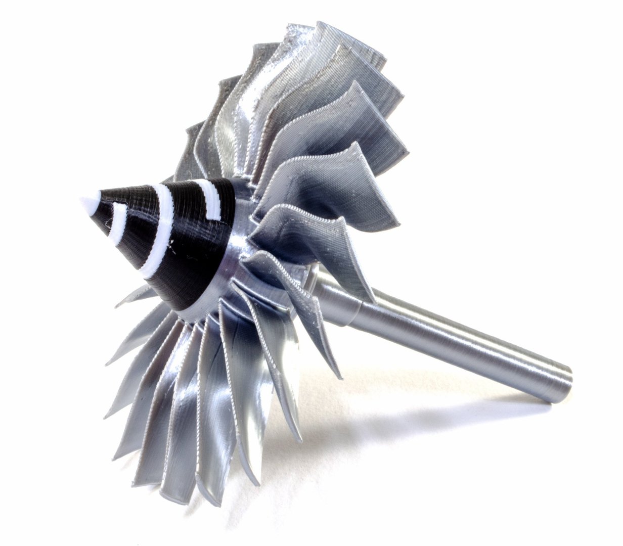
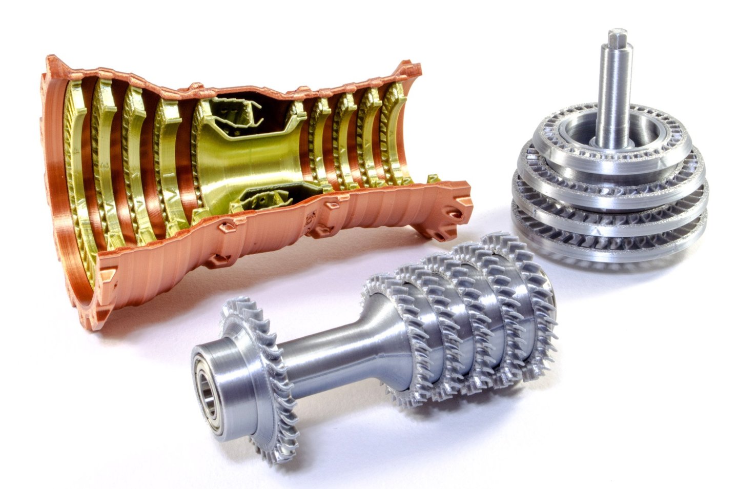
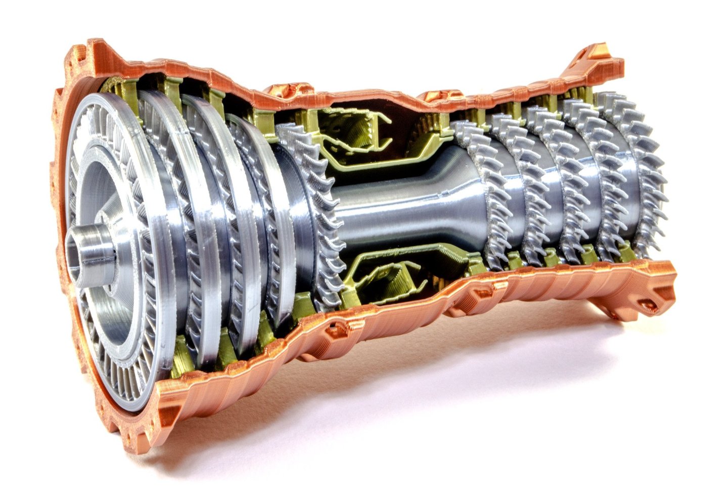
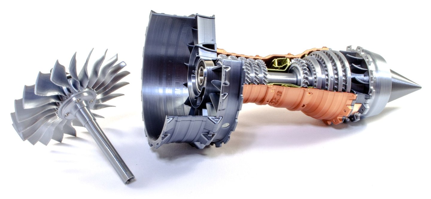
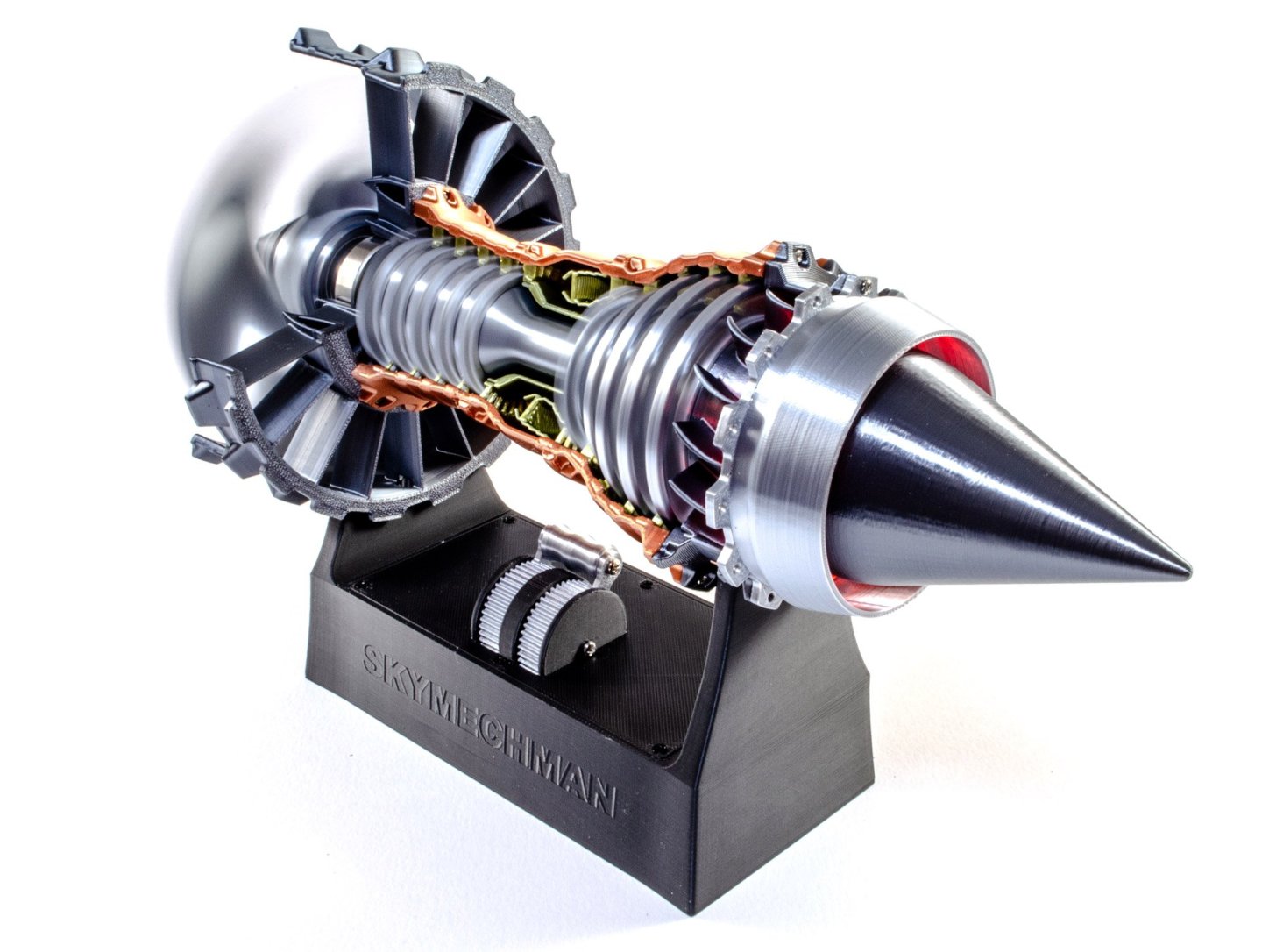
1:25 Rolls Royce Trent-900 Turbofan - SKYMECH - via EngineDIY Available from EngineDIY for $99.99 The Rolls-Royce Trent 900 is a high-bypass turbofan produced by Rolls-Royce plc to power the Airbus A380, competing with the Engine Alliance GP7000. Initially proposed for the Boeing 747-500/600X in July 1996, this first application was later abandoned but it was offered for the A3XX, launched as the A380 in December 2000. It first ran on 18 March 2003, made its maiden flight on 17 May 2004 on an A340 testbed, and was certified by the EASA on 29 October 2004. Producing up to 374 kN (84,000 lbf), the Trent 900 has the three shaft architecture of the Rolls-Royce Trent family with a 2.95 m (116 in) fan. It has a 8.5–8.7:1 bypass ratio and a 37–39:1 overall pressure ratio. The Trent 900 is an axial flow, high bypass turbofan with the three coaxial shafts of the Rolls-Royce Trent family. The 2.95 m (116 in) fan with swept blades is driven by a 5-stage LP turbine, the 8-stage IP compressor and the 6-stage HP compressor are both powered by a single stage turbine, with the HP spool rotating in the opposite direction of the others. It has a single annular combustor and is controlled by an Electronic Engine Controller. Abridged from Wikipedia The kit This is certainly the most inexpensive of the turbofan kits I've looked at here, but the first indicator of reason is the weight of the box. It's very light indeed. This kit is mostly made from 3D-printed parts, made with some very strong, metallic resins. Some sections are also pre-built. The kit is packed into an attractive and glossy black box, with a single line drawing image of the Rolls Royce Trent-900 on the side. The bus is opened via a top lifting flap. Inside the box are two trays of parts. This tray contains the main forward ring and fan (under the white styrene protector), and two pre-assembled units. These are the tail cone with its electronics, and also the display stand with more electronics. This tray has only pre-assembled unit; namely the main body which is made in a copper coloured material, with internal stators in a brass colour. Other parts here are various compressor blade rings, spinner, turbine shafts, bearings, screws, and the only tool you will need...namely a small screwdriver. Work begins by taking the six blade rings for the high pressure turbine. The first five simply slide and click onto the turbine shaft, in order of decreasing size. Arrows on all parts indicate the orientation of the parts, and the fit is incredibly accurate and positive. The last ring fits at the foot of the shaft as seen in the final image. A bearing is then pushed into each side of the turbine shaft, to complete this assembly. The next assembly is the low pressure turbine. This assembles in exactly the same way as the previous unit...arrows are used to align the turbines to the shaft. This time there are only four to fit, with two of these being identical. It's now the turn of the main impeller to be fitted to the drive shaft. Self-tapping screws are used to fit this. As a precaution, I only used absolute minimum of torque to screw the parts together, but that was probably just me as the parts are very robust. The spinner is then pushed into place. This is printed in two colours to create the spiral, which is a safety feature of the real engine. The main fan blade housing has a cutaway section so the modeller will be able to see the interior parts rotating. This is simply fitted with a bearing. The main engine body is an extremely attractive single-piece unit, as I mentioned earlier. We now take this and also push together both the high and low pressure turbine units. The fan unit actually fits quite easily into the engine body. There is some flex in the materials and a small push allows the fan to be quickly inserted without any fuss. The tail cone is called the 'power module' in this kit. That is because it holds the drive motor and all of the electronics associated with rotating the engine. This and the main fan unit fit together by means of a keyed slot in the shaft. More self-tapping screws are now used to assemble both parts. The main fan housing unit is now screwed to the turbofan body. The fan assembly then simply pushes into the engine to lock it in place. There's no connecting wires between the engine and the base. Instead, two copper contacts on the power module, are used to transfer voltage from the base to the engine. These sit together with some positivity, and the engine can then be powered. When the lever is first moved, it will click, and the red LEDs at the tail, will light. Push further and the engine begins to rotate. The speed can be controlled depending on how far you push or pull the lever. Operation is fairly quiet too, and unlike the other engines, this one doesn't have the pre-recorded jet engine sound. It isn't missed or needed though. You can see the fan in operation in the bottom photo. OPERATIONAL VIDEO Conclusion This little kit took less than an hour to build, and was actually a very satisfying little project and highly enjoyable. Being 3D printed was no detriment to the fun and final appearance of the completed model, and of course, those materials help to create a relatively cheap way of building your own little turbofan engine for your office desk. The kit itself is high quality and fits like a dream. The only thing I'd do myself would be to make a Rolls Royce display plate to cover the manufacturer name on the base. My sincere thanks to the folks at EngineDIY for sending out this great little kit for the purposes of review here at Model Ship World. To buy directly, click the link at the top of this article.


-
I'm unaware of that. The system isn't accepting email addresses as logins. This is something the software creators have picked up on, and are changing it, wholesale for all forum members. If I try to login, I'm asked for username and password. You're saying yours asks for email? Can you screenshot that? I just added a new test account here and it's asking for username and password, as per this account.
-
Good evening, all! The software we use is currently version v4.x. We are edging, month by month, closer to V5. When we hit a new number, these are usually massive revisions, and we've only had one of those on MSW in the past 10yrs. It is anticipated that within the next months that we will need to upgrade to the new version. To improve security, we will all have to login using our registered email address. At the moment, we simply use our username. EVERYONE....please take note of the registered email address on your MSW account, by looking at your Account Settings. Take note of it. Maybe you no longer use your registered address. If not, change it. I will be prompted to reauthorise your account. That's all there is to it to be prepared for the change, when it happens. When it is imminent, I will give you a further period of notice. Maybe you no longer have access to that email account. The same will apply. The short of this is PLEASE TAKE NOTICE OF YOUR REGISTERED EMAIL ADDRESS and correct it if it's not current.
- 14 replies
-
- 23
-
-
-
That really does look excellent, and your work is so clean.
-
I’ll watch the new videos tonight.