James H
-
Posts
6,126 -
Joined
-
Last visited
Content Type
Profiles
Forums
Gallery
Events
Everything posted by James H
-
 For the time, I'm locking this topic. Nothing is imminent with resurrecting this project.
 -
There are a small number of things which stalled this build, regarding contents. Those are between Amati and myself at this stage of the project.
-
Unknown Royal Yacht kit.
James H replied to Lucius Molchany's topic in - Kit build logs for subjects built from 1751 - 1800
No. Only if they are rip off copies of legitimate designs. Please don't spread that misinformation here. There are legitimate Chinese kits, and as you have that wrong belief, I assume you have gained that information on different shores to MSW. -
That was a hell of a save! Congrats on the sale too. Well deserved.
- 587 replies
-
- 5
-

-

-
- Indefatigable
- Vanguard Models
- (and 1 more)
-
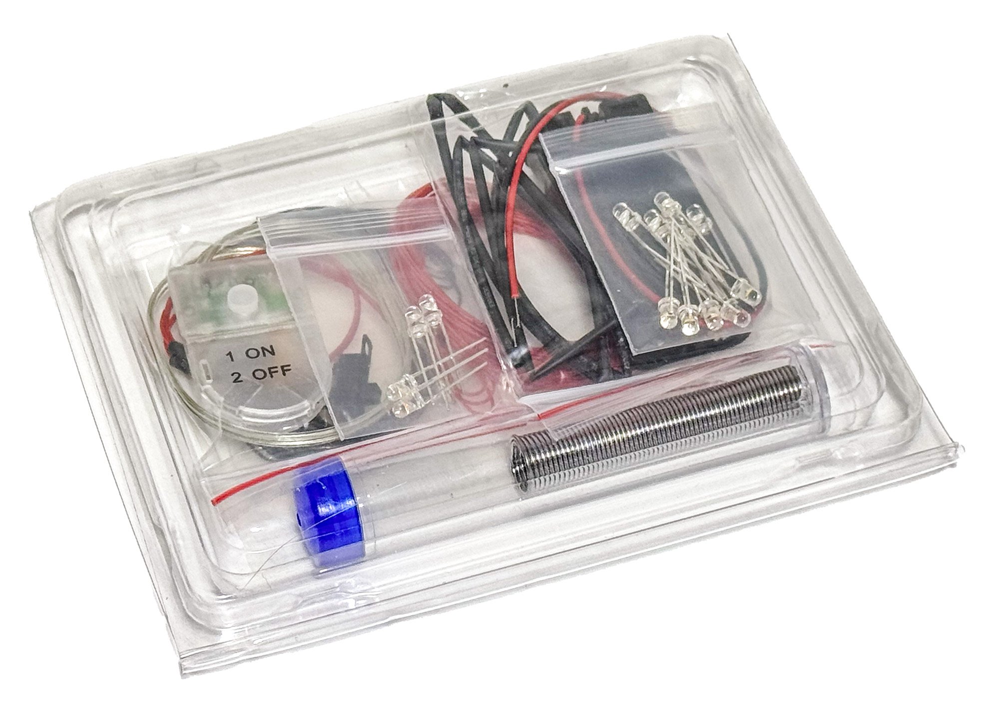
I have one of the lighting sets here, and they are very nice. Here's a photo.

-
That is stunning, beyond words. If I'd built that, I'd retire my tools. Simply gorgeous.
- 840 replies
-
- 5
-
-
- winchelsea
- Syren Ship Model Company
- (and 1 more)
-
Ok, I've pruned this topic, but left Chris's last post where he quotes Vane. Vane's post was pertinent. From here, let's get back to usual business and not sermons from old, dusty journals on the minutiae of armament on 18th century seafaring vessels.
-
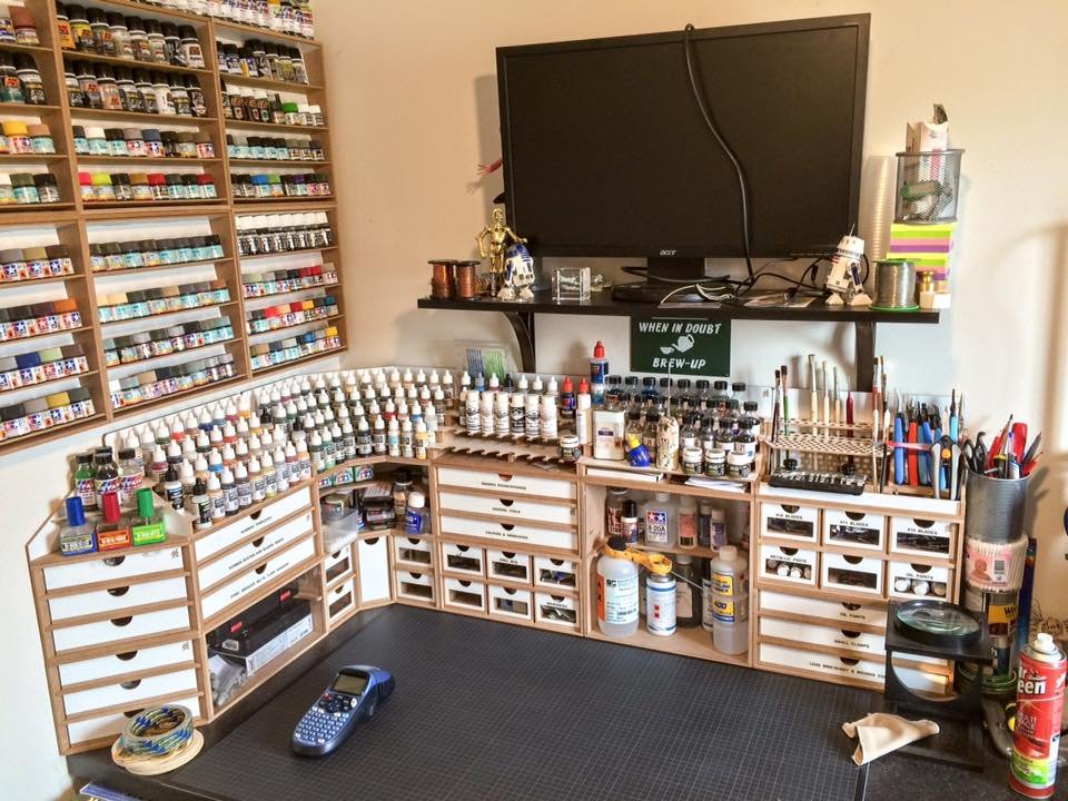
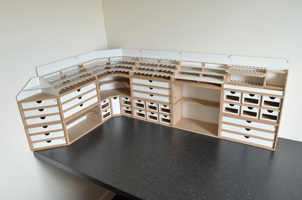
These are a couple of photos of my setup. All of the bench storage is from HobbyZone in Poland.
- 32 replies
-
- 10
-

-
-
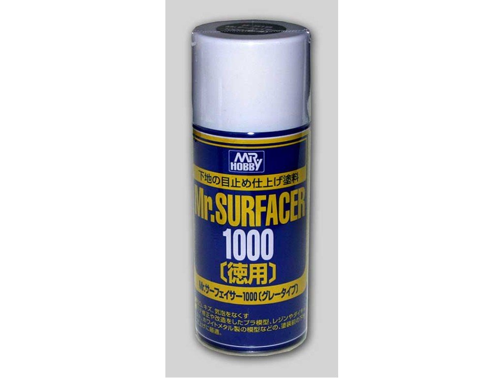
I consider Tamiya Fine Surface Primer to be one of the very best around. If the Mr Surfacer equivalent isn't banned, then that is every bit as good.
-
That's exactly what it is.
-
Remember that this kit will have been developed at the same time as another Vic kit from this year. That isn't the fault of any company. AL seem to be offering something akin to the original cutaway Bounty kit they once did, but on steroids. Fair play. If it appeals, then give it a try. Choice is good.
-
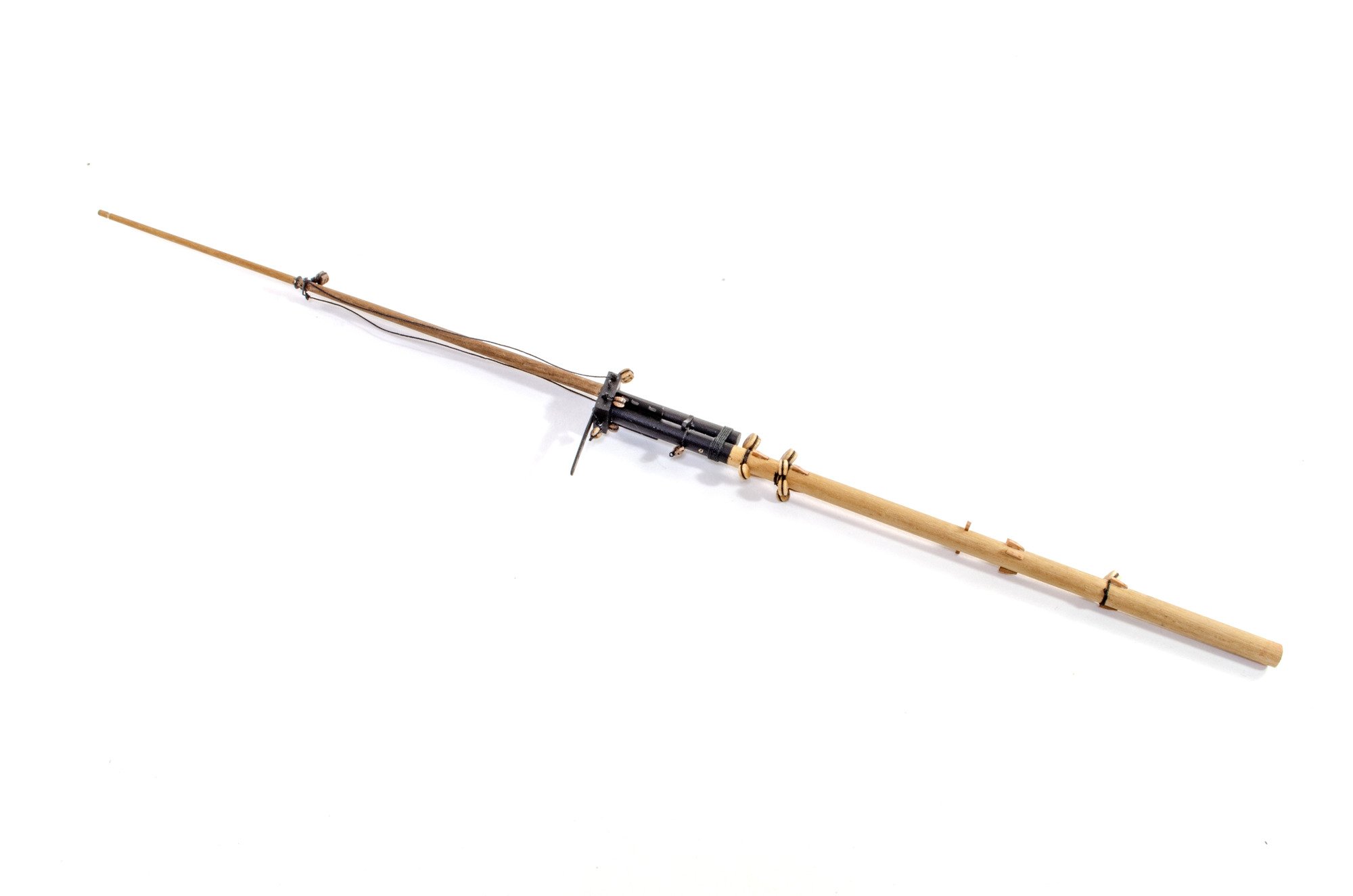
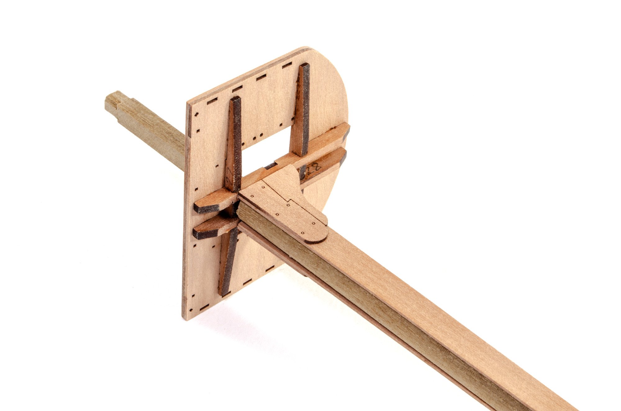
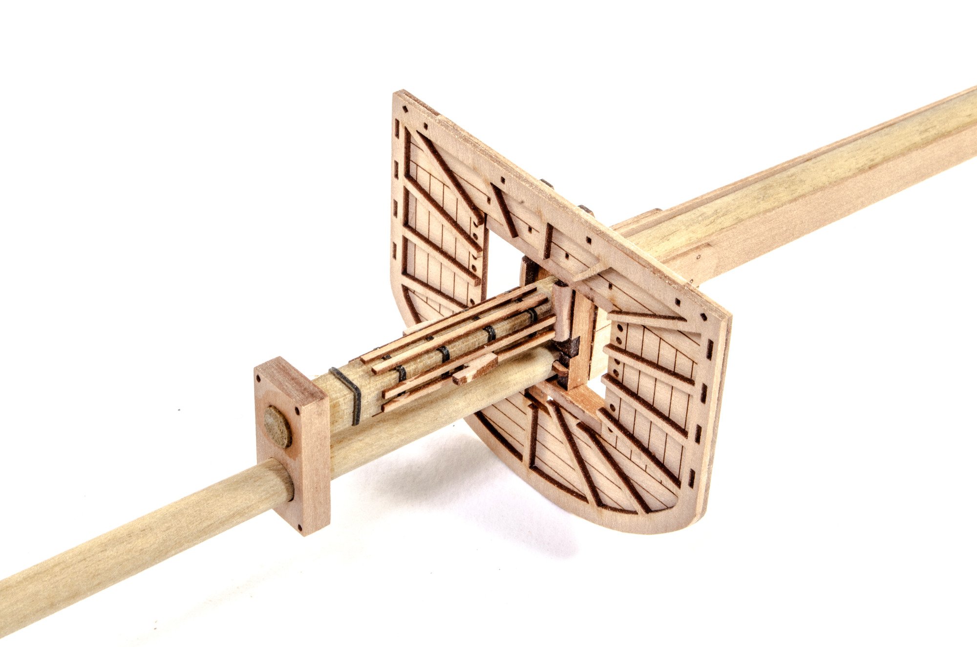
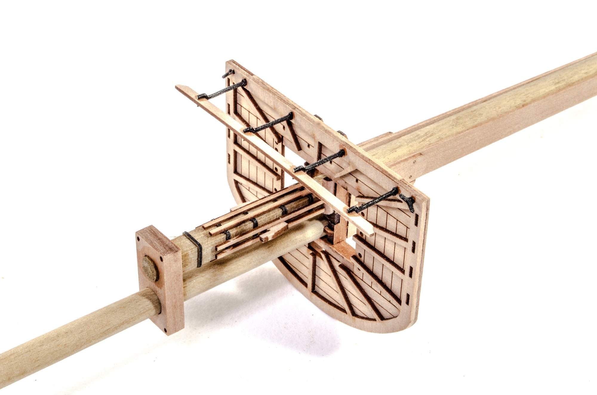
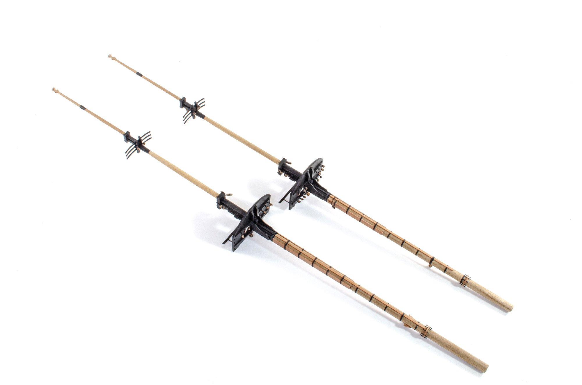
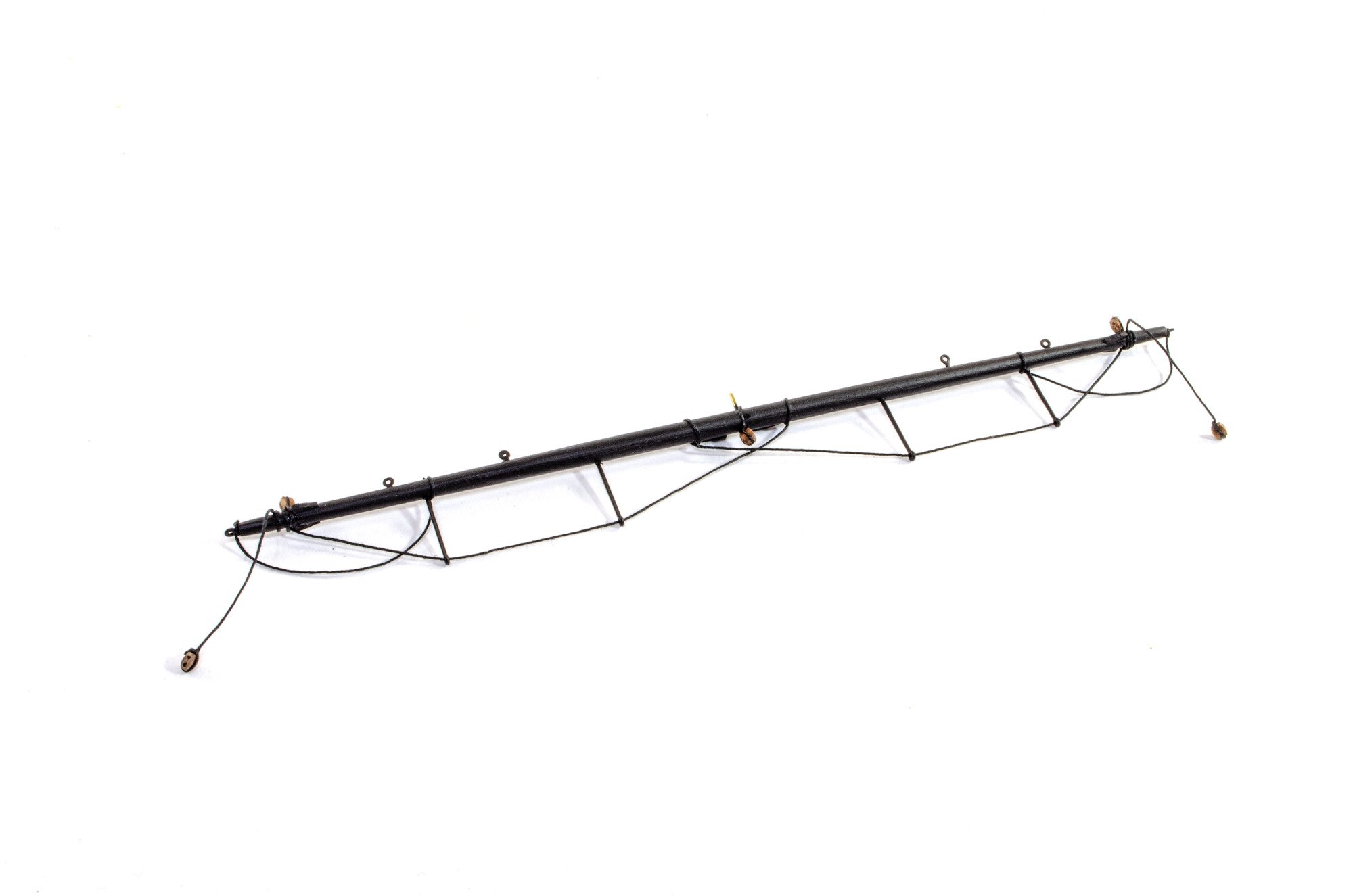
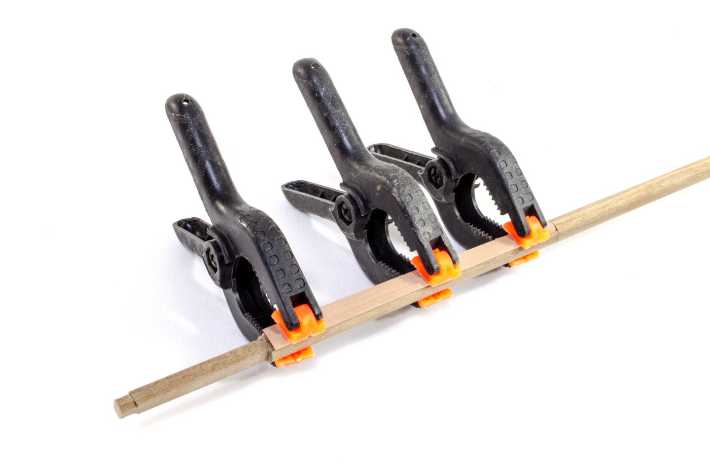
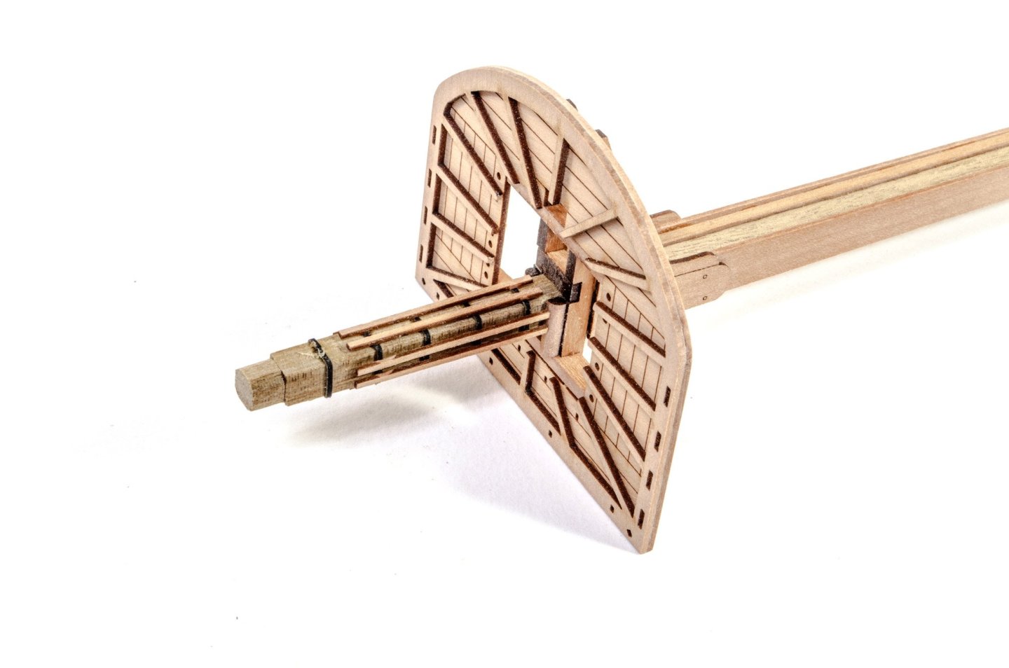
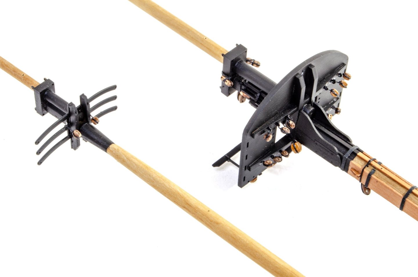
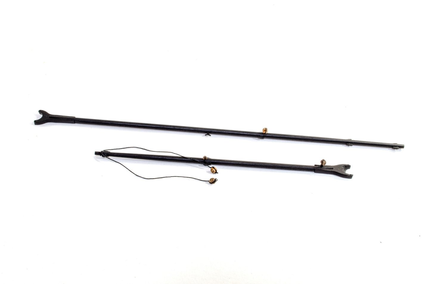
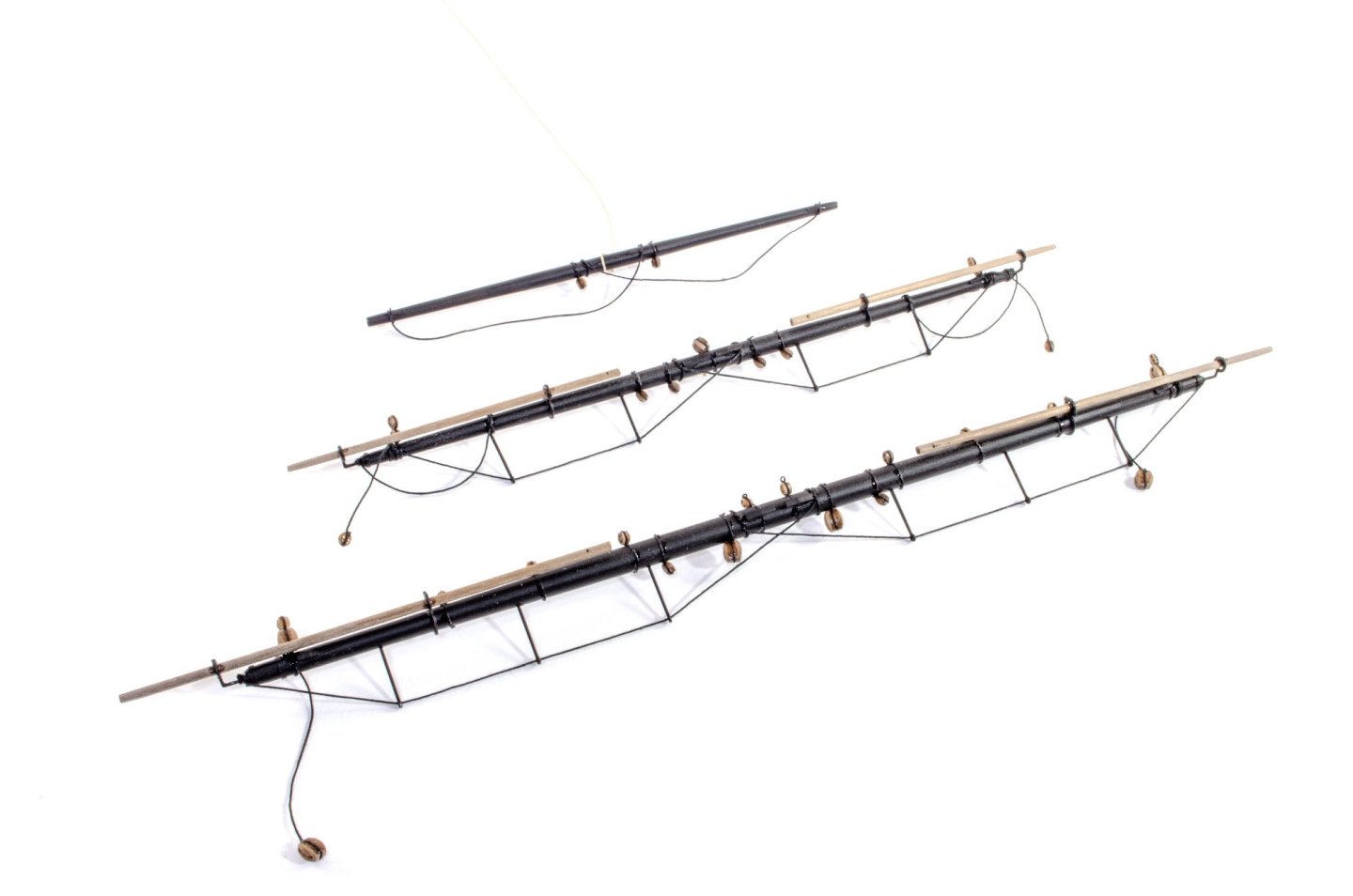
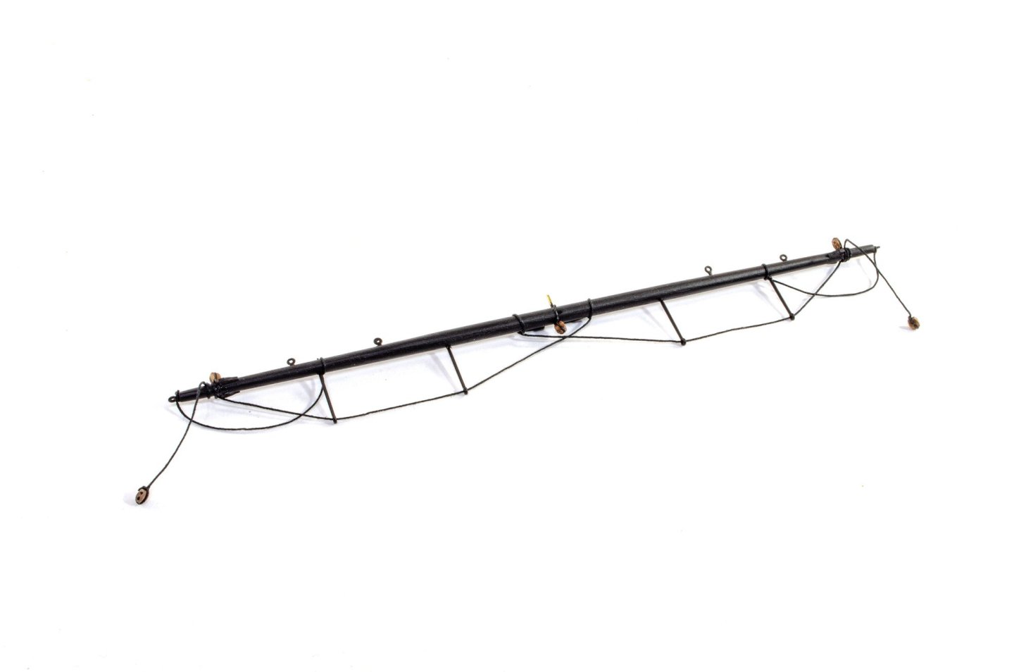
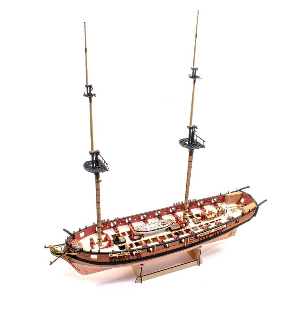
This is likely to be my penultimate update as the next one should show this rigged and finished. That'll be a nice way to conclude this, so until this, these are a few photos of Harpy's masting, including some photos of the yards, gaff, boom, spritsail yard and the completed bowsprit. I've concluded this with a photo of Harpy as she currently looks. No text is really needed for this as the photos are self-explanatory and perfectly follow the convention you've seen in other VM build logs. Hope you like the results so far. ]


- 76 replies
-
- 29
-
-
-
- Harpy
- Vanguard Models
- (and 1 more)
-
Very pretty! Are you fully masting and rigging?
-
I refer you to this post:
-
Come on, at least one clue? 😆
-
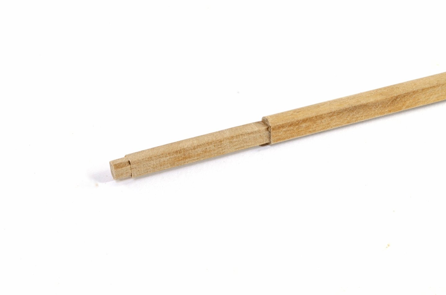
A pin pusher isn't a precision tool. It's just for slapping in brass pins anywhere along the place where the joint is. There's a knack to using one quickly so you get the pins roughly where you need them. The Modelcraft pin pusher works real well and of course you can set it so it doesn't push all the way into the wood. Quite neat.
-
That’s the exact same one I use.
-
We're going to do something a little different. We'll start a log which will show you some of the design processes as they move along, culminating in the prototype build.
-
I will be starting a build log for this. Could be an idea to open one where Chris can post in the development which then morphs into the build as it progresses.
-
Please, if anyone IS an NRG member, they need to let me know as I manually add these logos. Adding your membership number will not automatically make the logo appear. I'm sure there are other topics in this forum which relate to this.
-
It does seem very cut and dried with those hints!
-
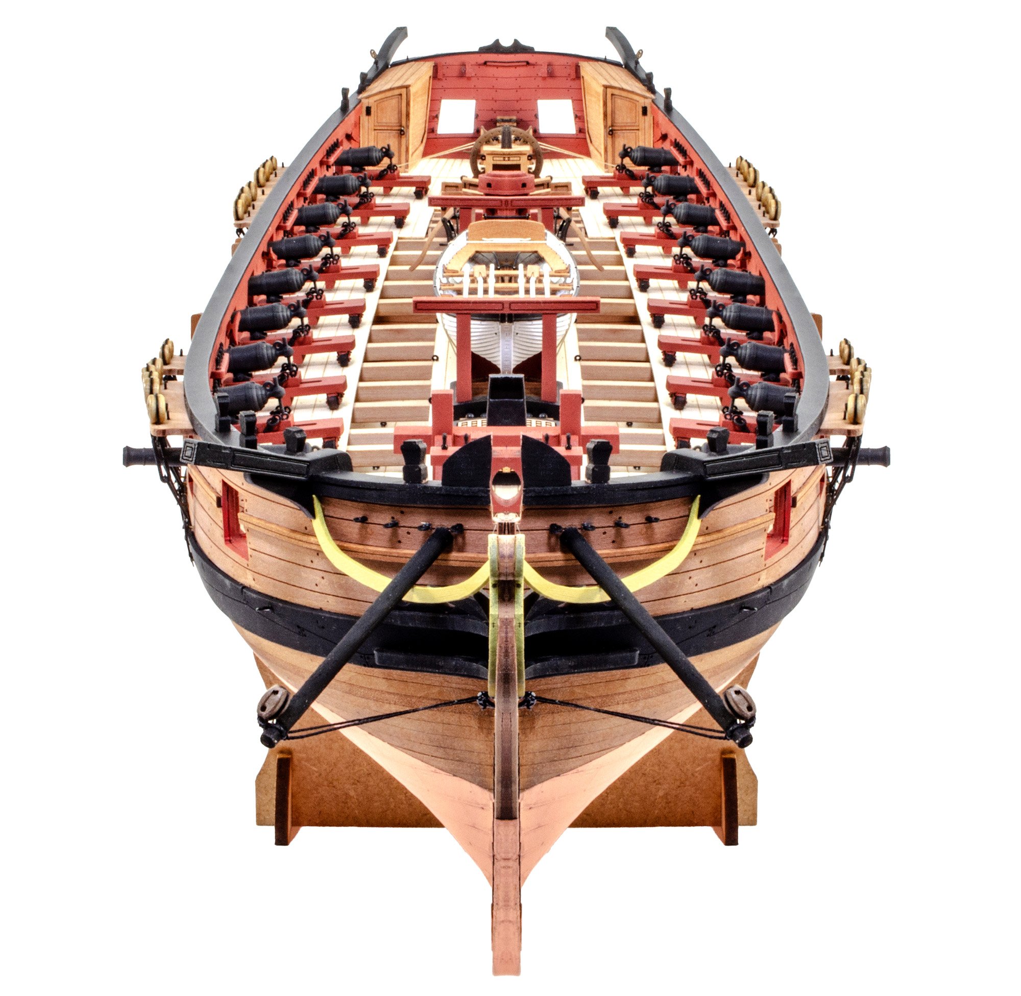
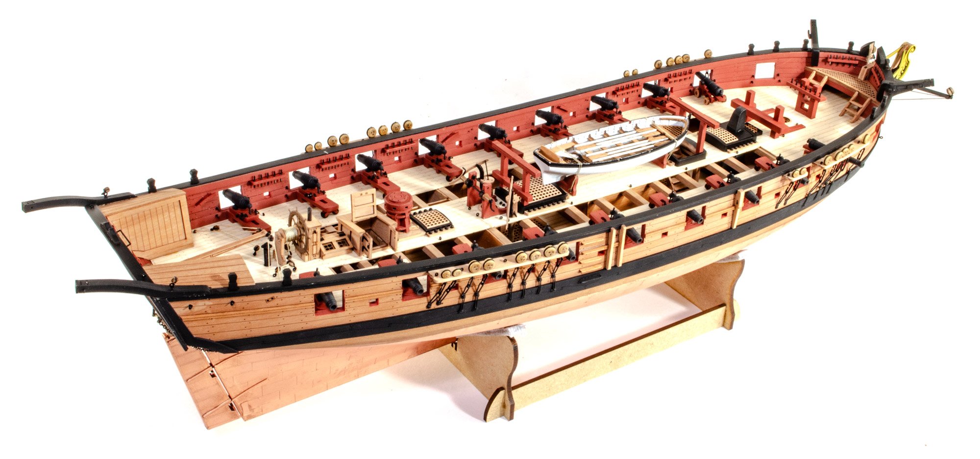
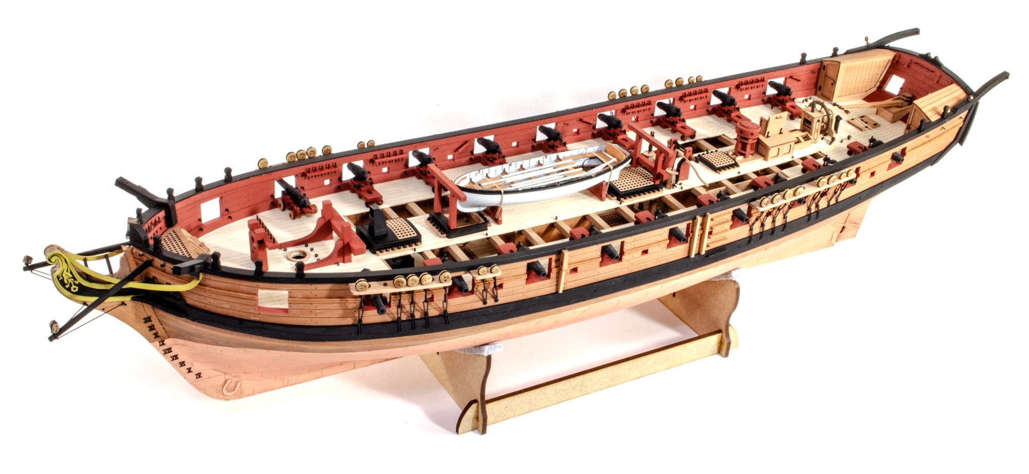
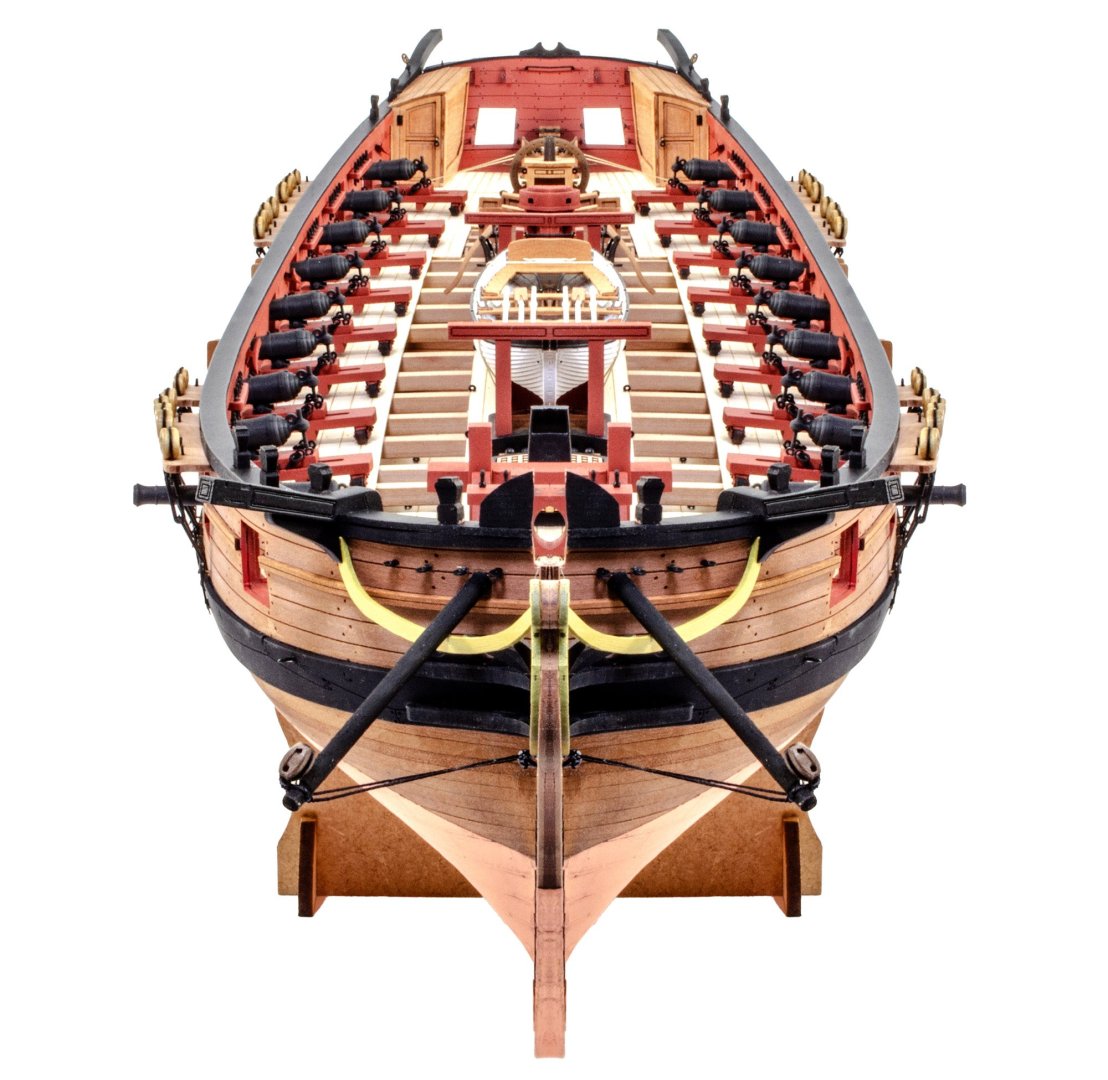
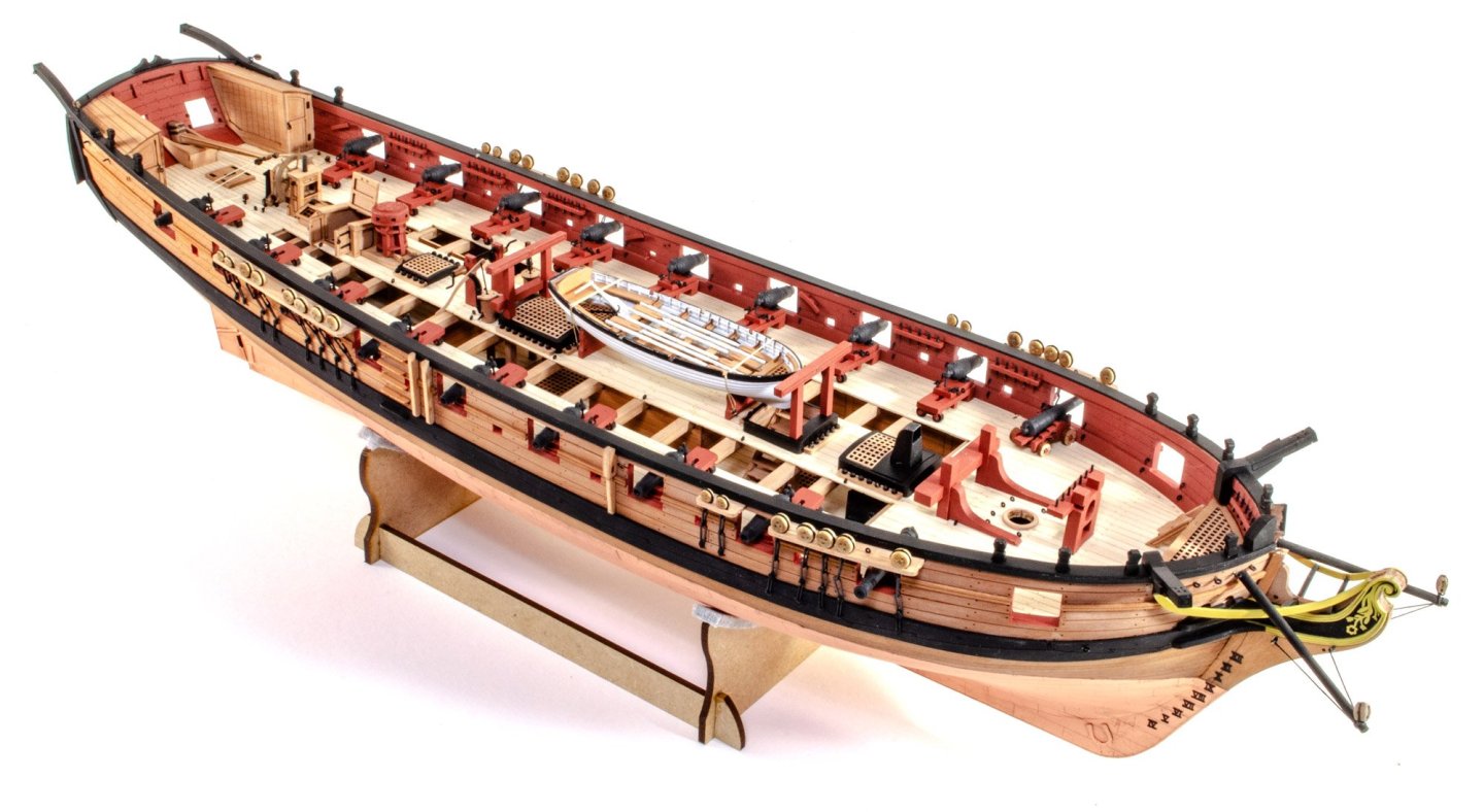
I couldn't let those dusty photos remain, so I gave Harpy a blast of canned air tonight, and some delicate brushing. Here are some new pics.


- 76 replies
-
- 28
-
-
-
-
- Harpy
- Vanguard Models
- (and 1 more)