thibaultron
-
Posts
2,952 -
Joined
-
Last visited
Content Type
Profiles
Forums
Gallery
Events
Everything posted by thibaultron
-
 I'll resume this log shortly. My desktop computer died, but I was able to get my files off it. I'm left with my laptop, which has less computing power and a lower resolution screen. The screen shots will thus be a little lower resolution. Sorry for the delays in finishing this tutorial, I spent quite a while trying to get my other computer going. It would intermittently either just turn off or not reliably turn on. Now it just won't turn on. It is either the motherboard, or the CPU.
 -
Great Work!!
-
I was surprised by that sentence in the Chappelle book, and was wondering if they had use a different arrangement. I've seen the strap type on ships several hundred years.
-
White Paint Issues
thibaultron replied to rynmss's topic in Painting, finishing and weathering products and techniques
Thaks for the advice to used white primer. In the next couple of weeks, I am going to be painting a mostly white ship! -
I've been reading Chappelle's "The American Fishing Schooners 1825 - 1935" and have come across something that has me confused, about how rudders were "hinged" before about 1880. In describing a particular ship built in 1887 "Her very sharp ends ... hollowed sternpost, and strap pintles and grudgeons were departures from contemporary fishing schooners." So if the strap pintles and grudgeons where not used previously, what method did they use before this to mount the rudders? One of my upcoming projects is the Flying Fish schooner, and I would like to put the proper hardware on her.
-
You could also place a sacrificial board behind the plywood.
-
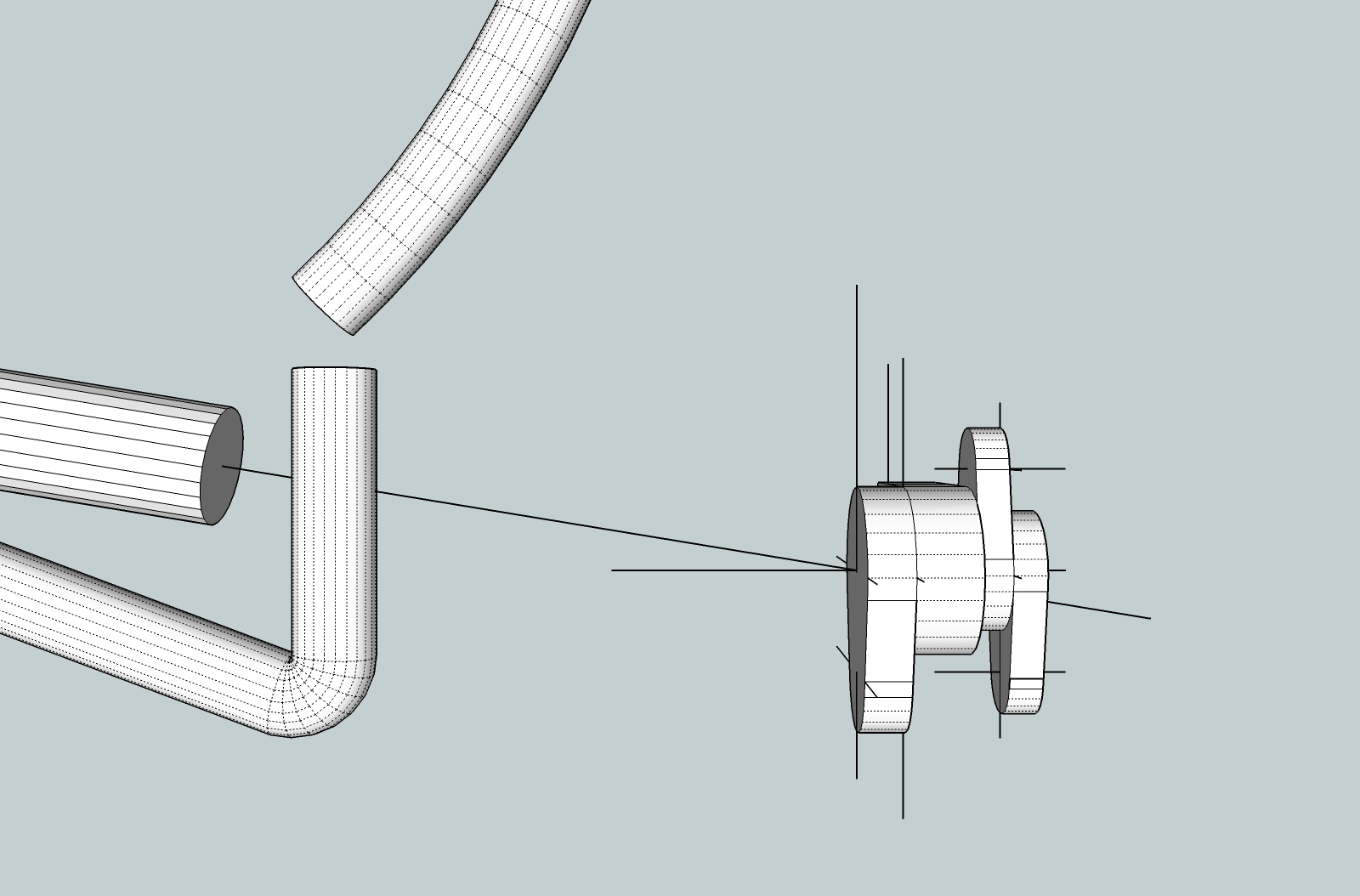
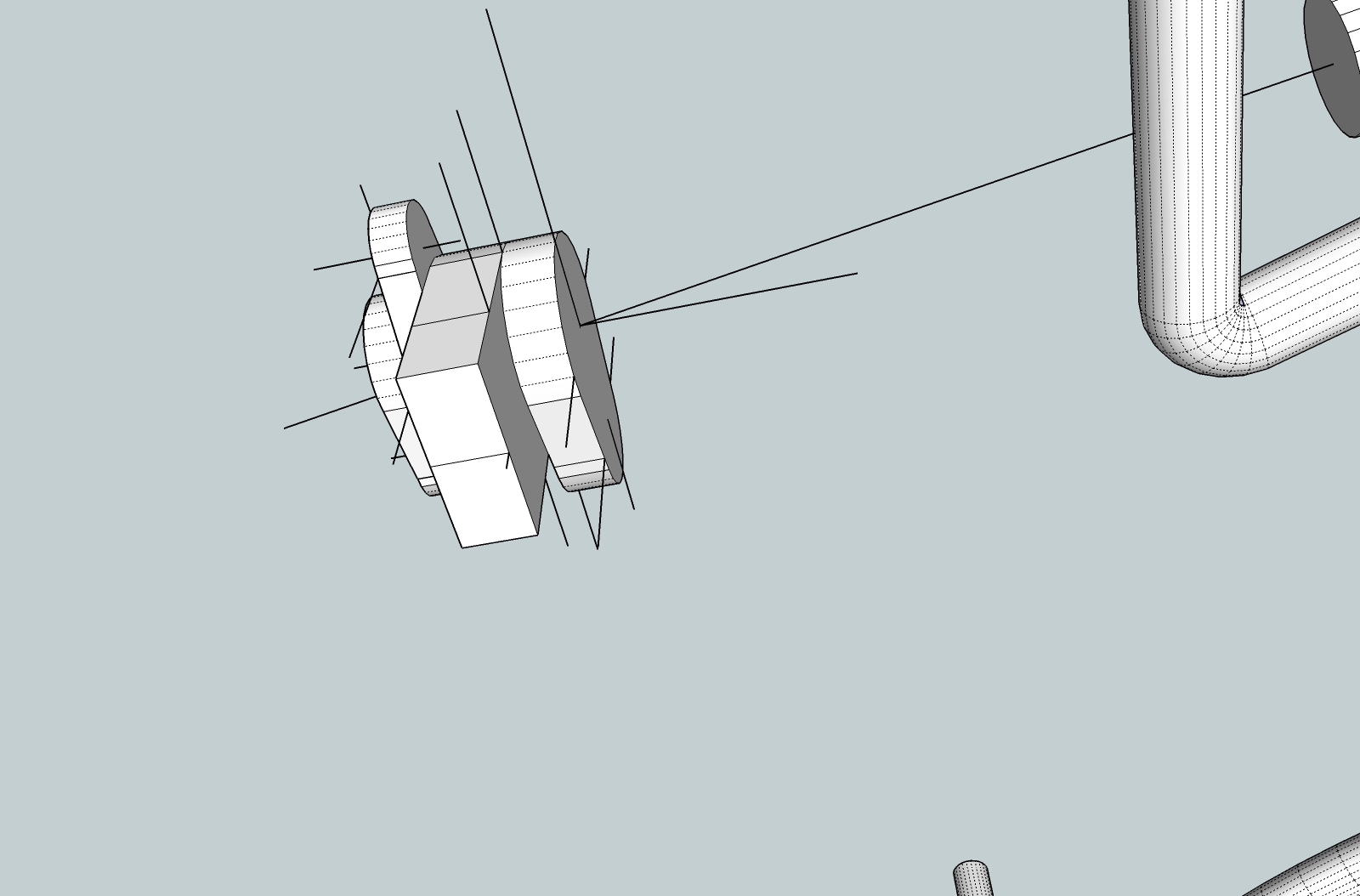
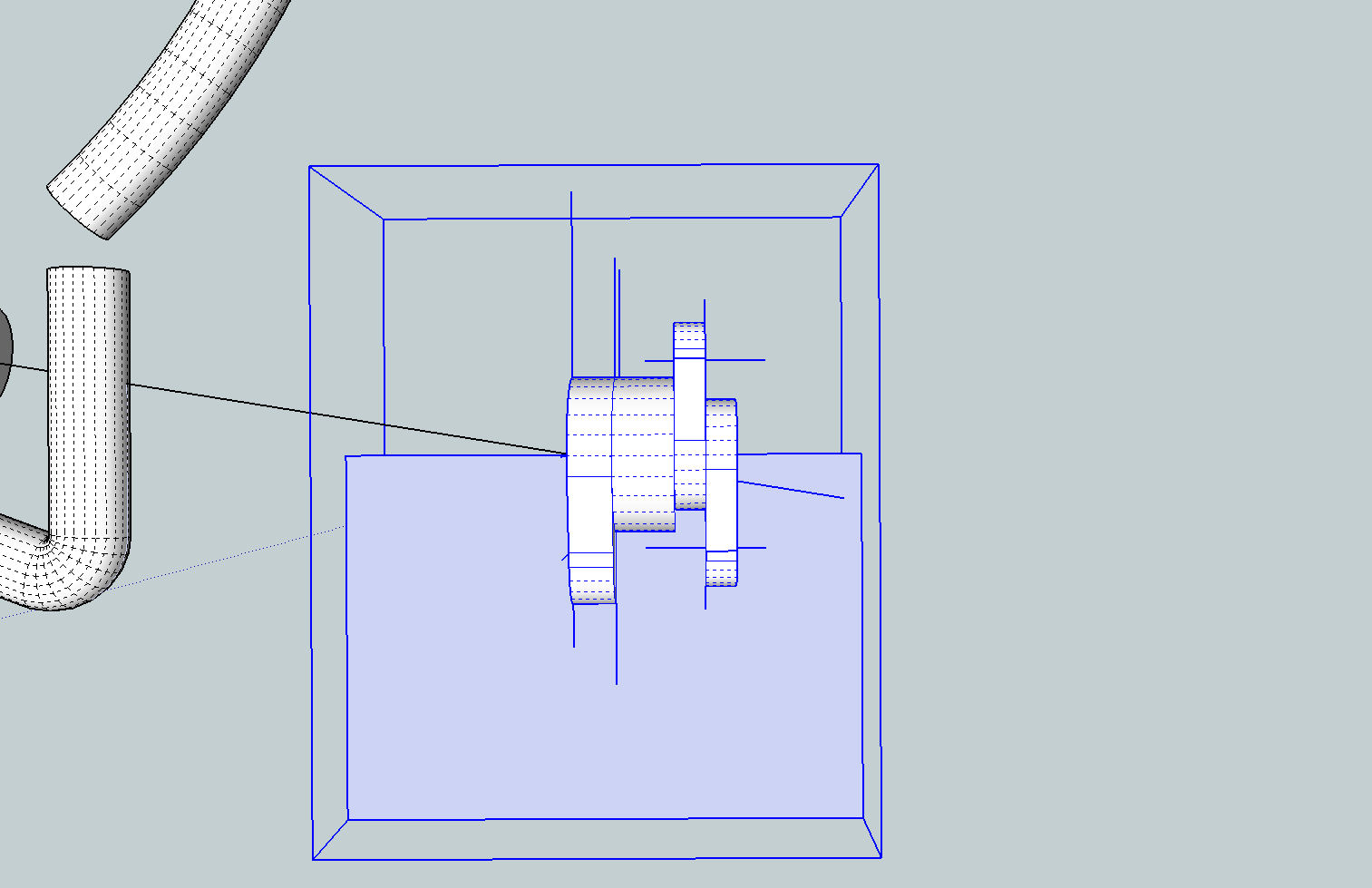
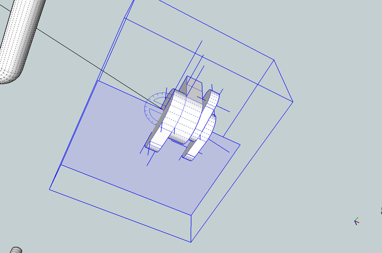
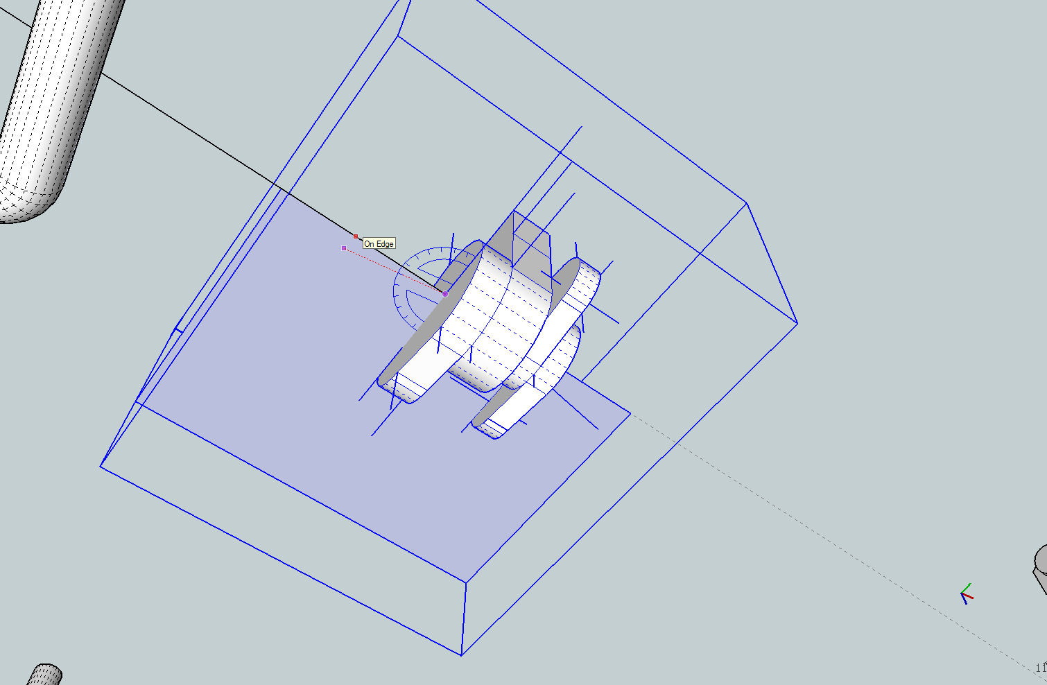
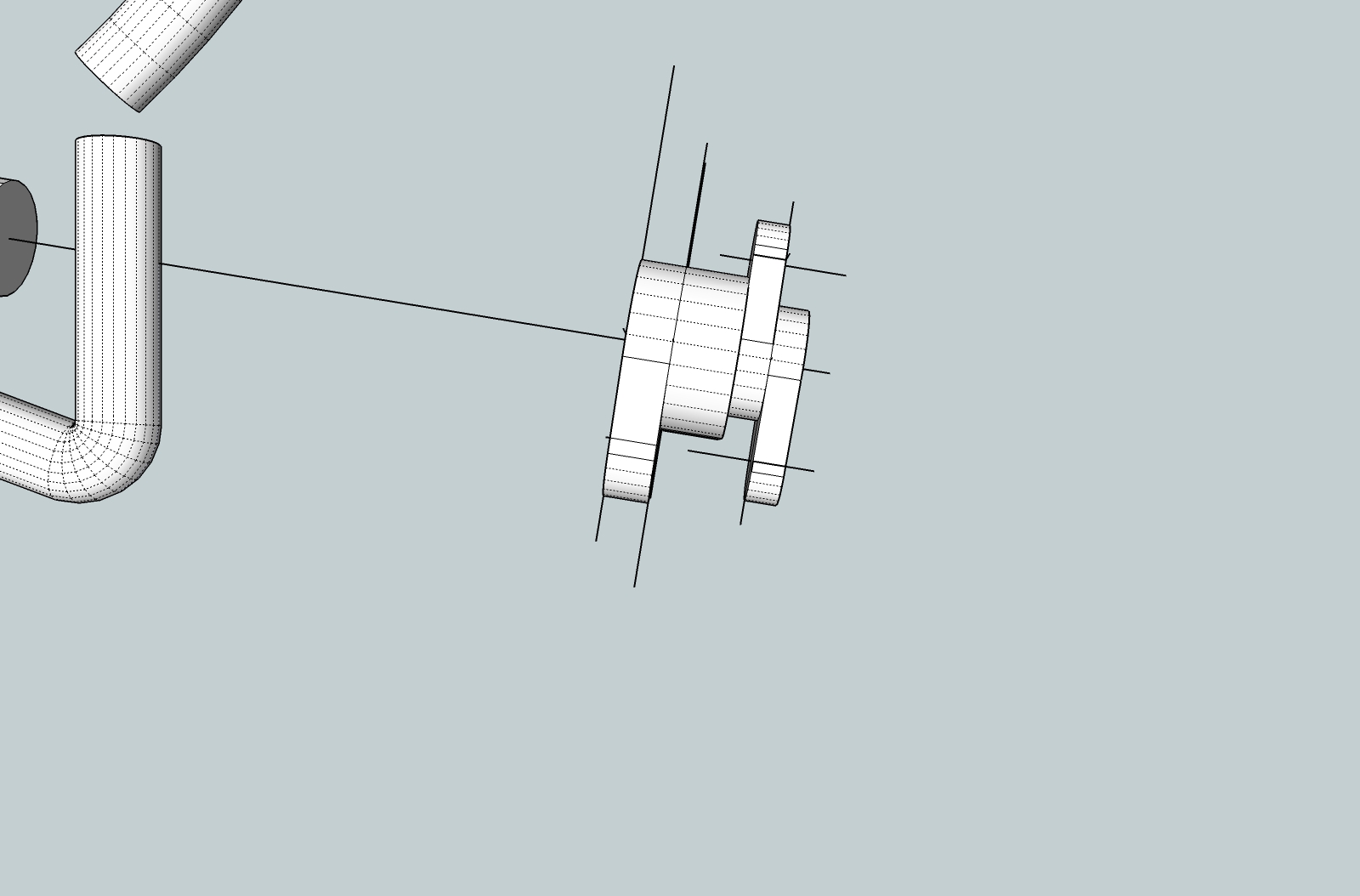
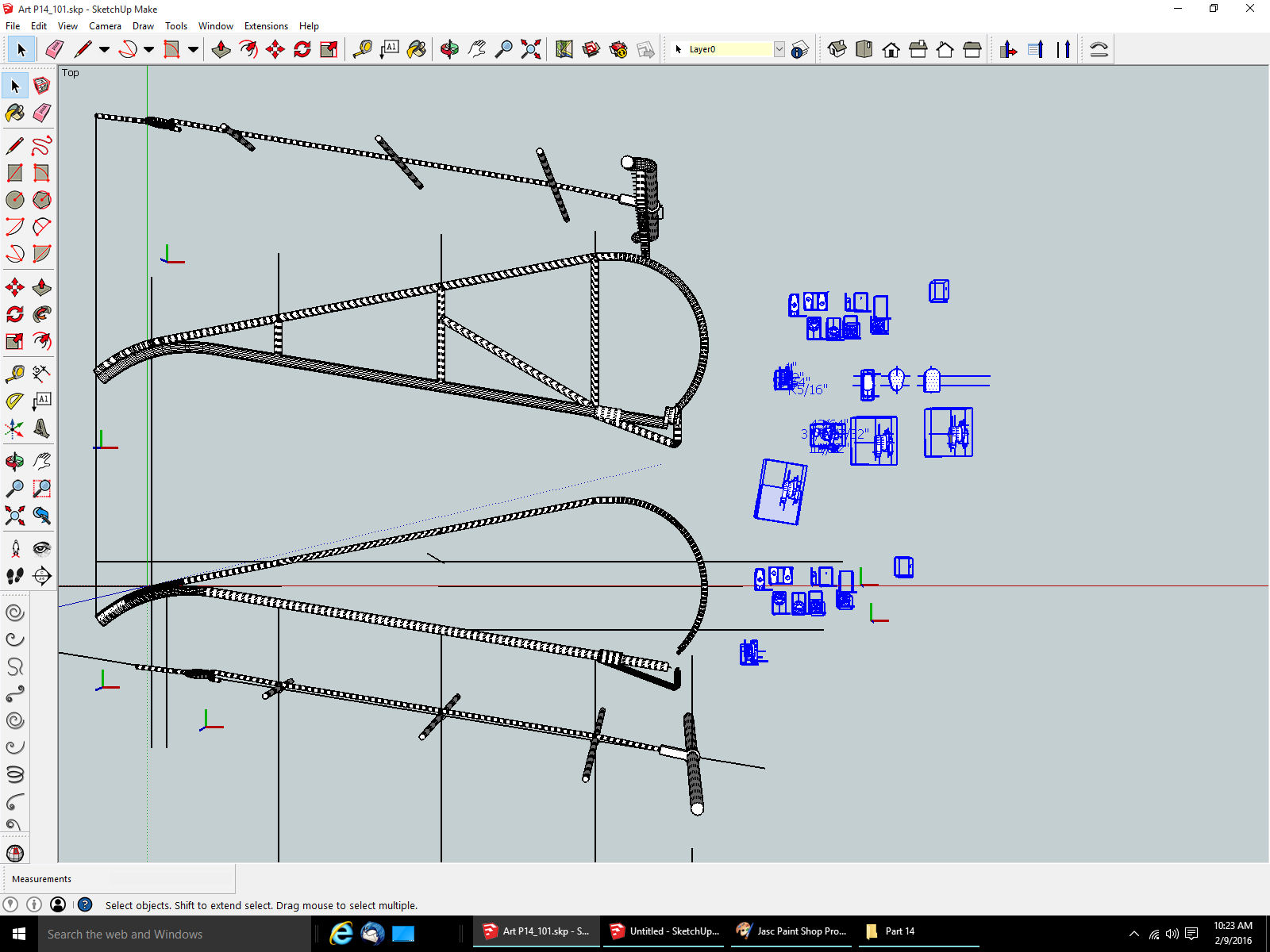
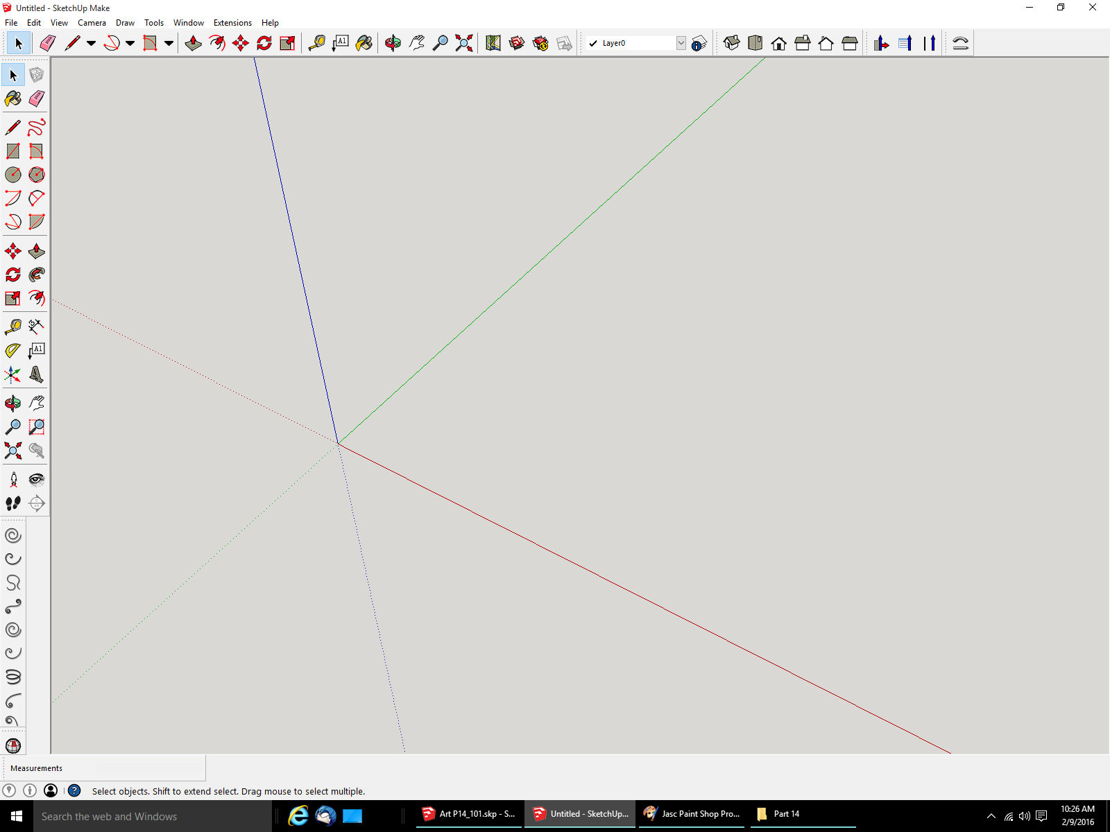
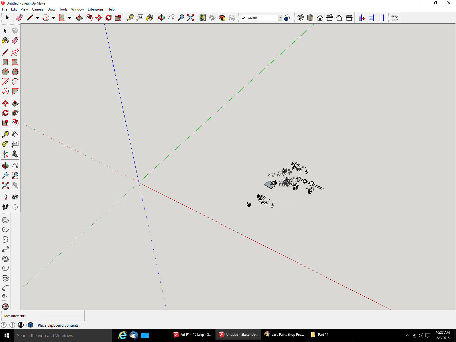
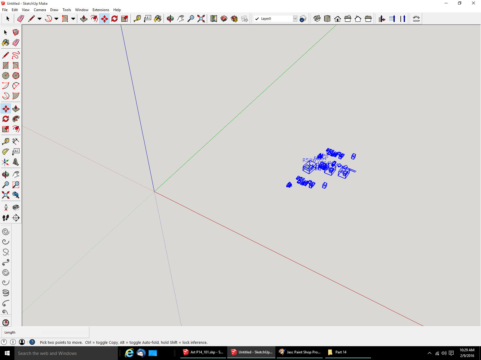
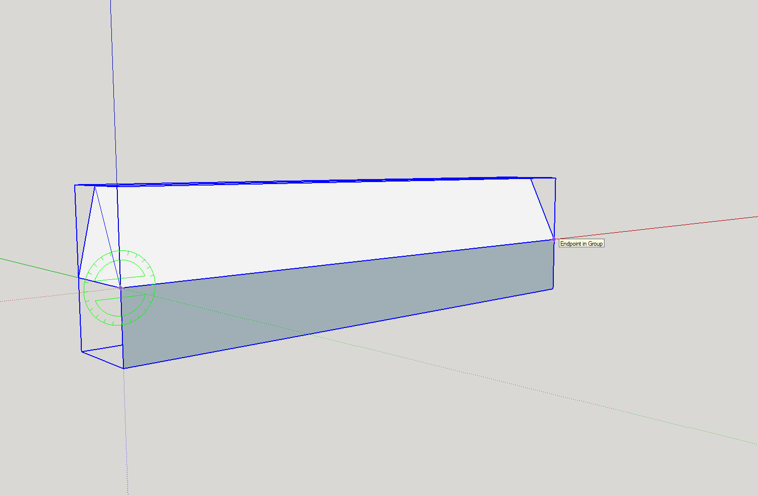
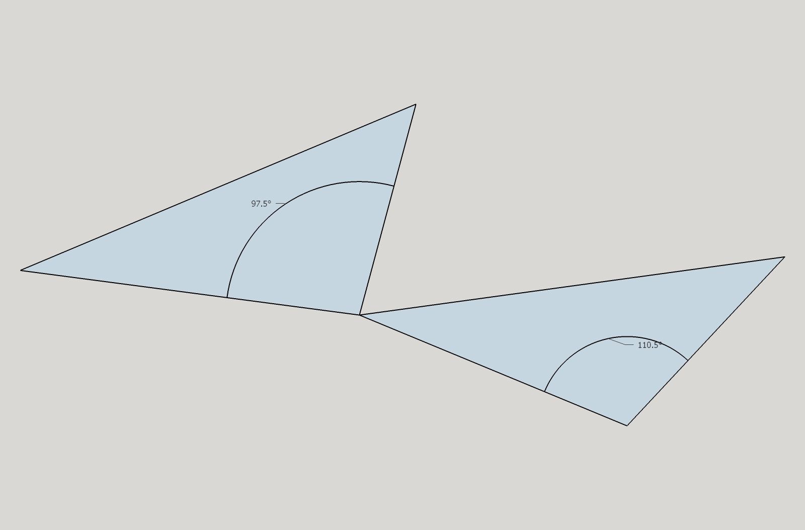
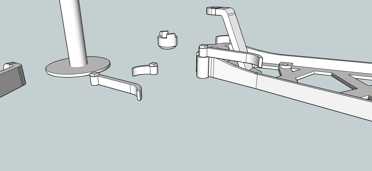
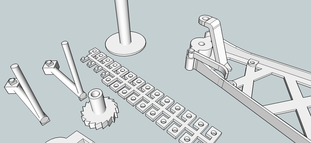
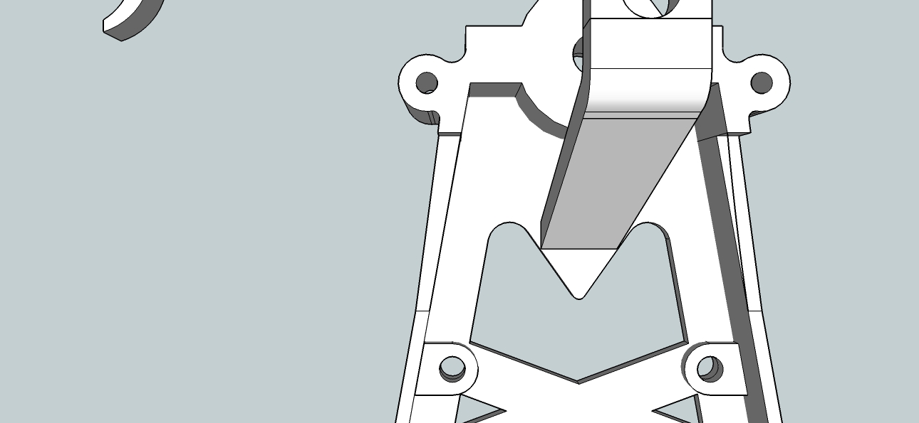
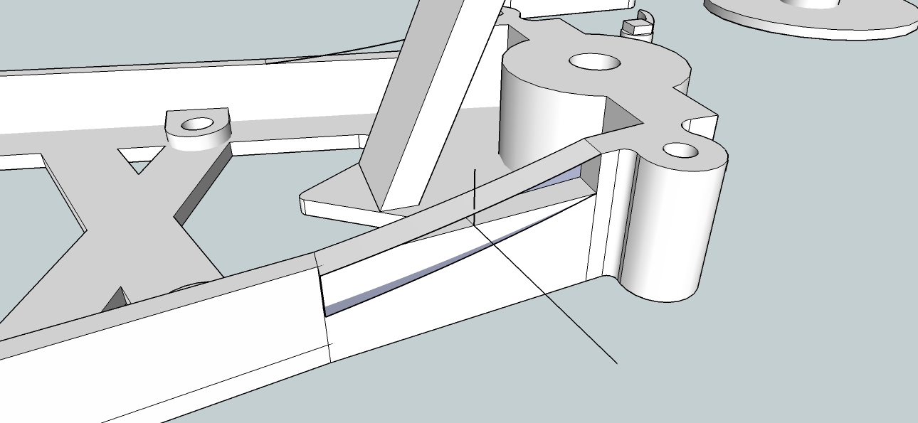
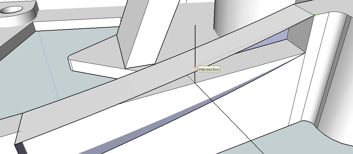
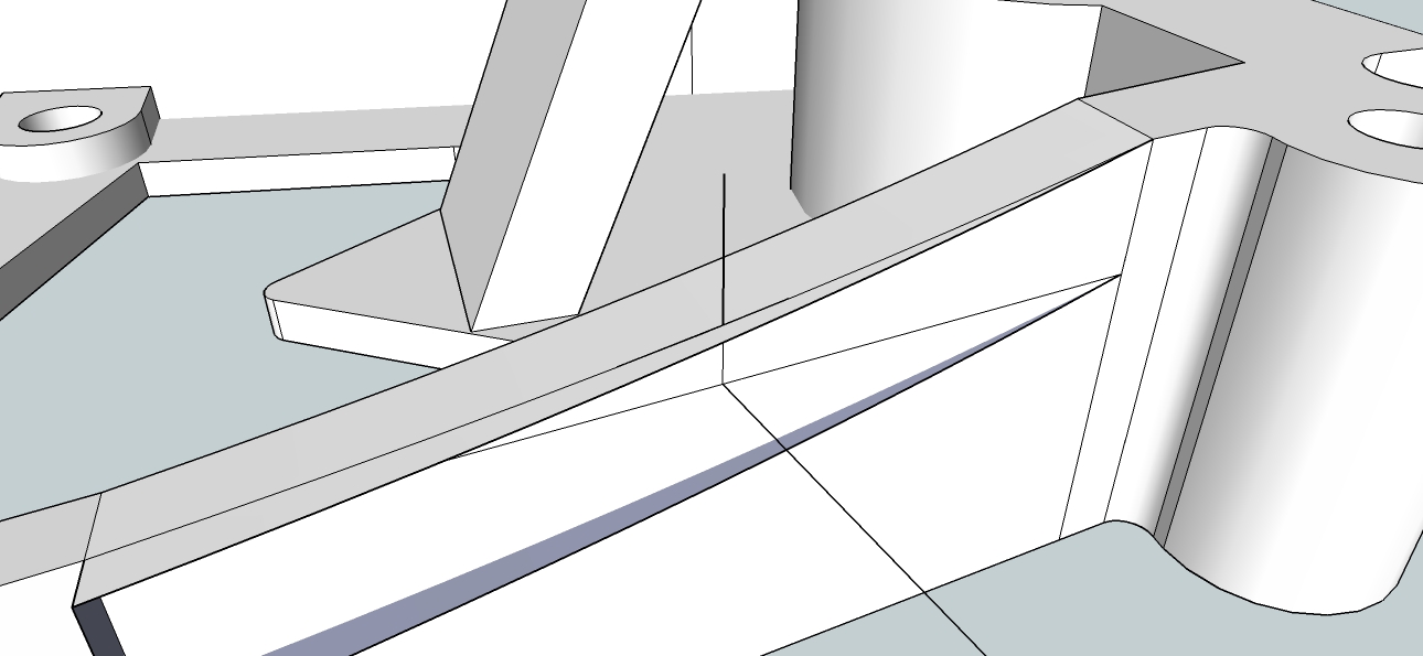
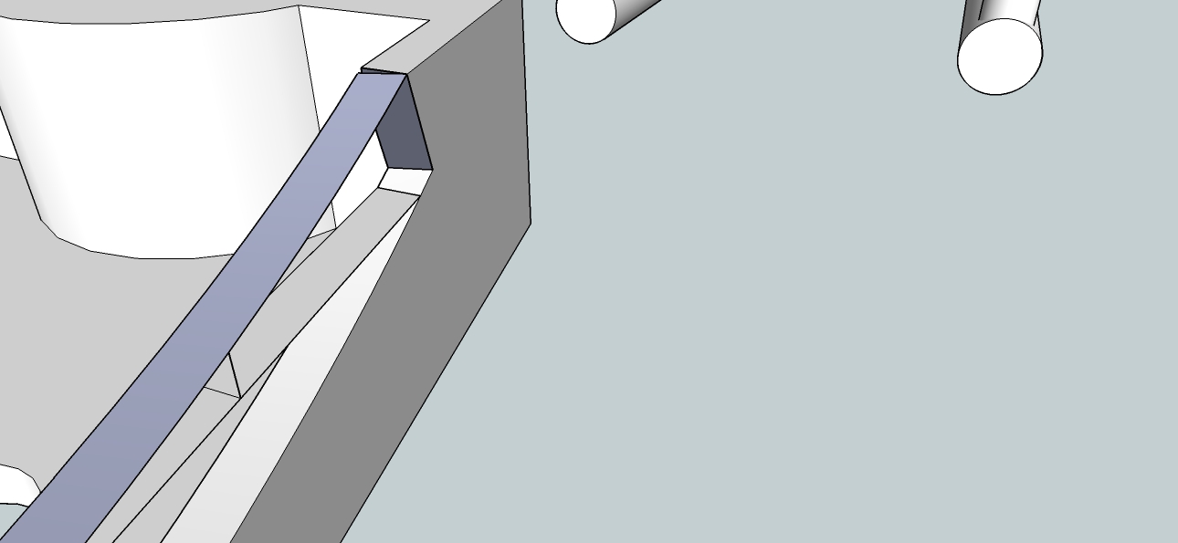
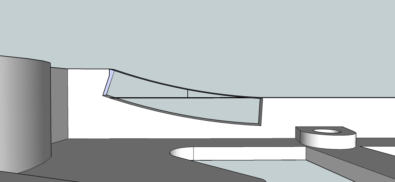
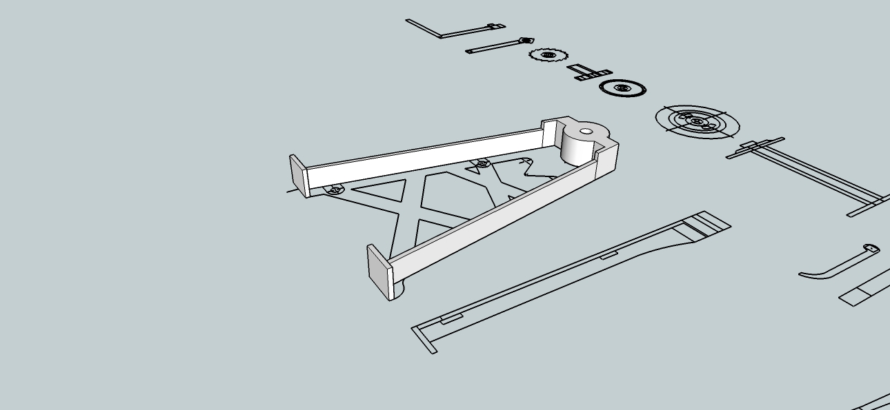
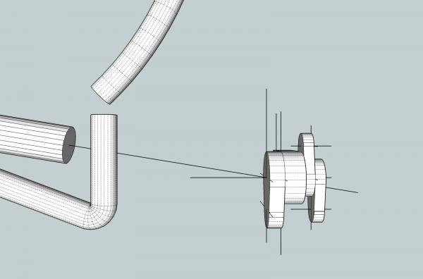
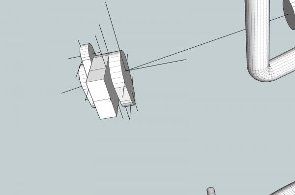
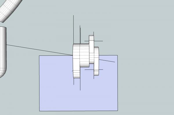
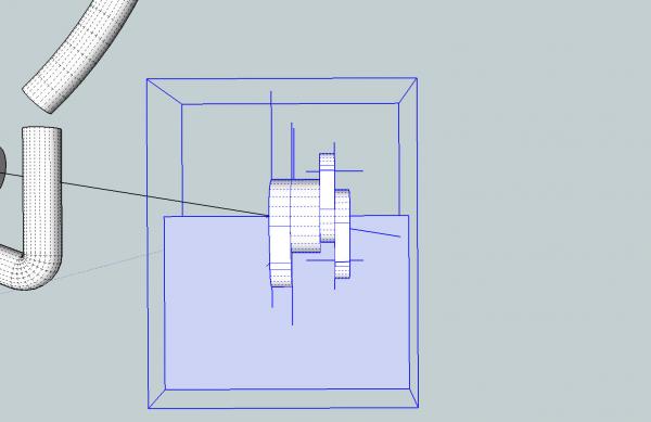
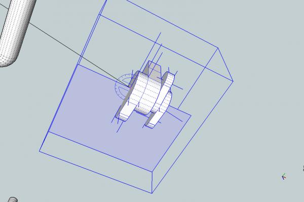
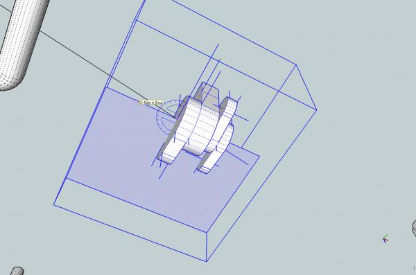
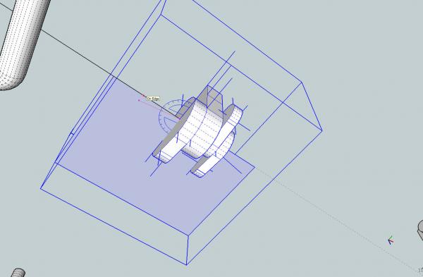
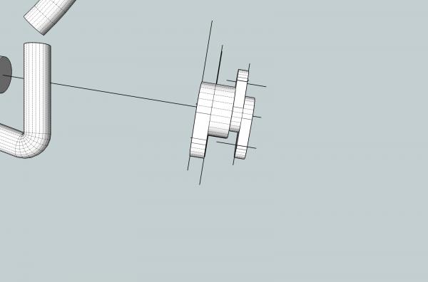
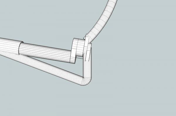
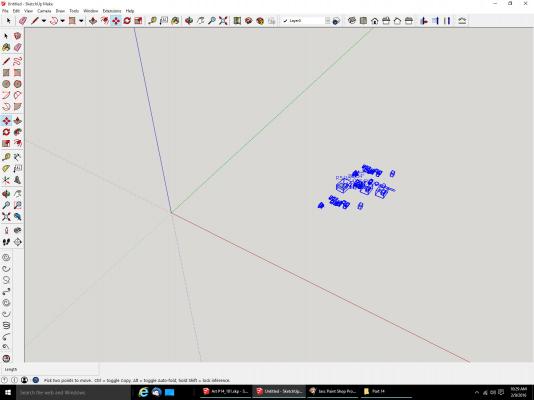
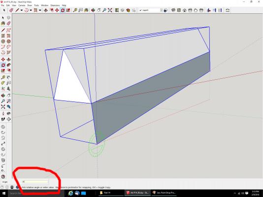
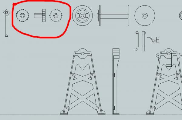
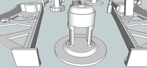
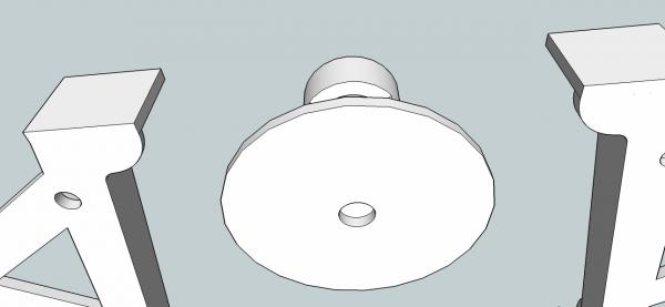
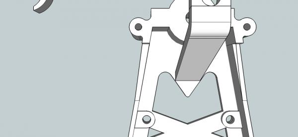
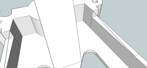
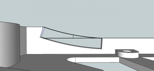
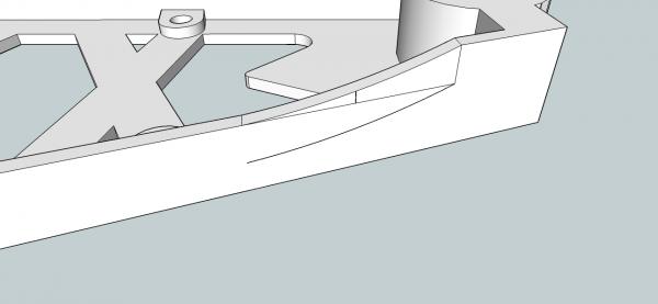
Part 14B Here is a real world example of this process. I needed to rotate the assembly below to match the angle of the lower part of the dredge frame. These are the ends of the various frame parts that are bolted together. I will have to blend them into the rods, as detailed in an earlier post. After selecting the rotation point, I selected a point on the edge of the rectangle, as a handle, I pulled it up until it fell on the line I wanted the rotated object to match. The object is now lined up at the correct angle. After moving it into place and cleaning it up it looks like this. Copying A Part From One Drawing To Another I recently ran into the situation where I had made a mistake several versions back on my drawing for the 1/64th scale dredge frame, but had done several things that I did not want to redo. So I needed to copy some parts of the drawing to the earlier version. SketchUp only allows you to have one drawing open at a time per program window. So to copy from one drawing to another, you have to open two different instances of the SketchUp program, and copy from one to another. Start up the first program and open the donor drawing. Then select the portions of the drawing you want to copy. Copy the highlighted portions, with either Ctrl C or Copy. Start a new SketchUp program. If copying to another existing drawing, open it. Next paste the objects to the new drawing using either Ctrl V, or Paste. The objects will be displayed, and you can move them around until you have them where you want them. Once they are properly placed, click the mouse to set them. They will be displayed in blue, like when you normally select object(s). They will be placed in the red/green plain (x and Z plane). If you need to rotate them, as I did here, group them, and use the regular or 90 degree rotate function (one of the plug-ins I mentioned at the start of the thread) to get them where you need them.


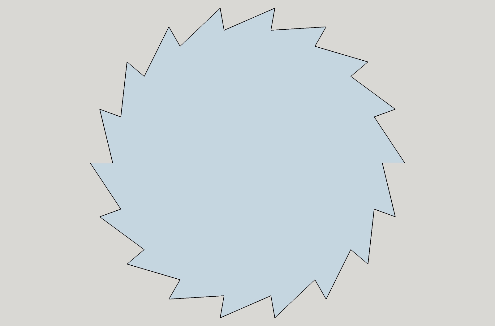
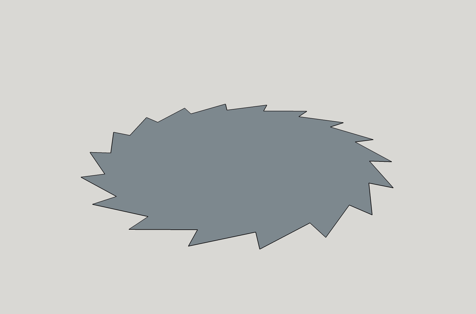
-
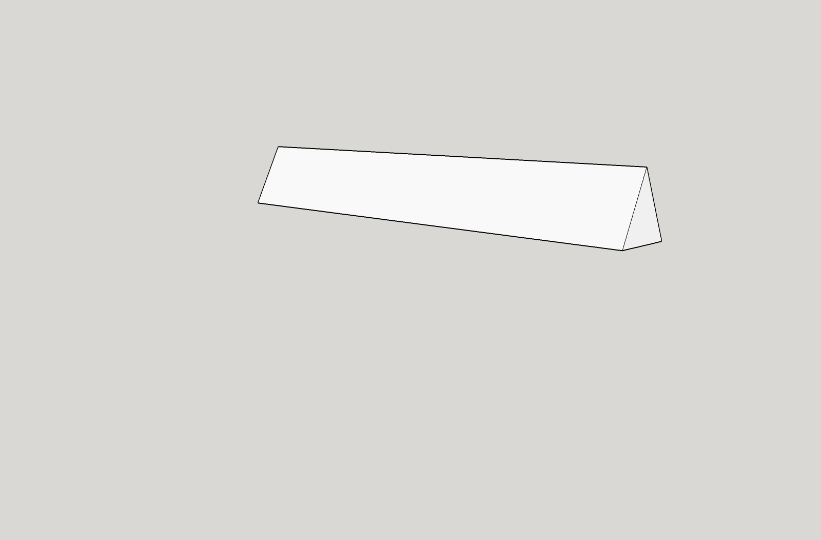
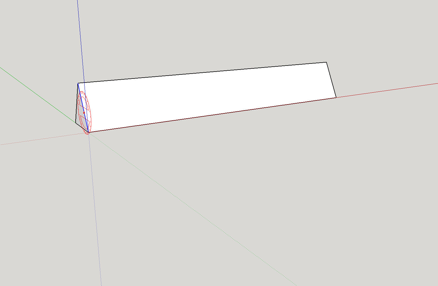
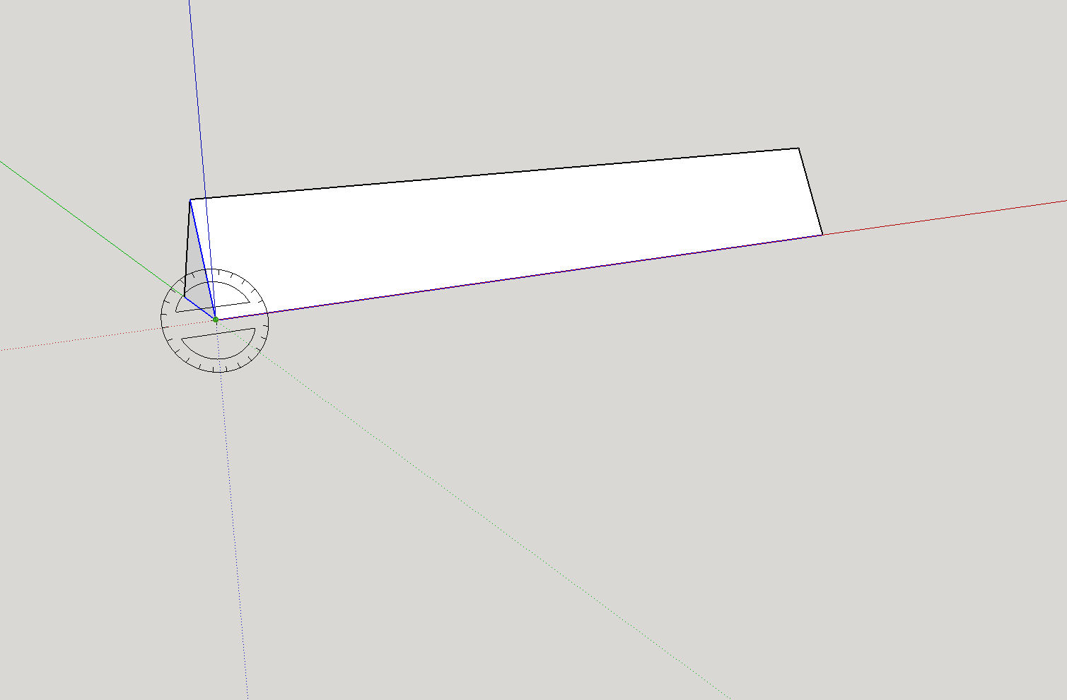
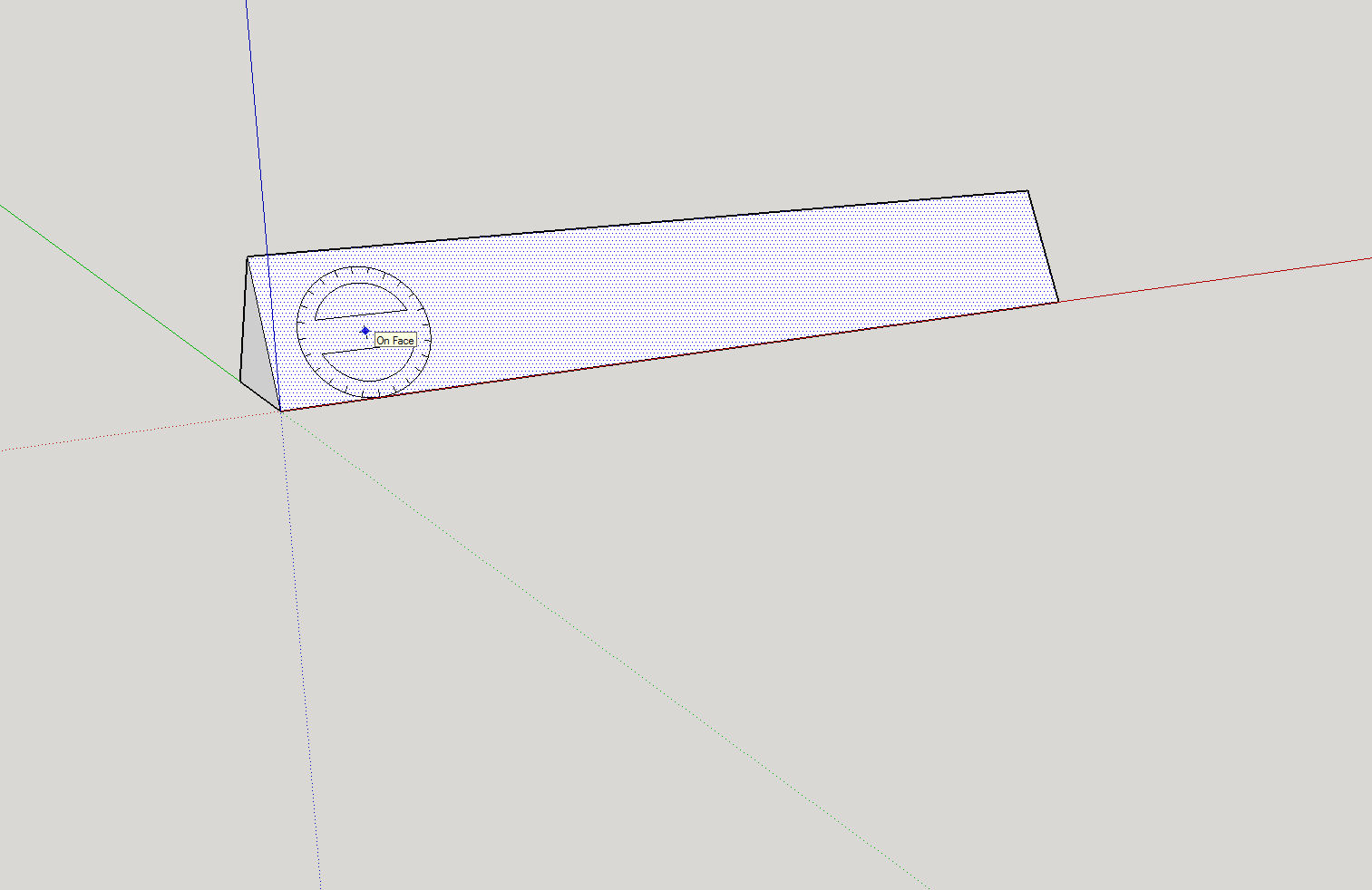
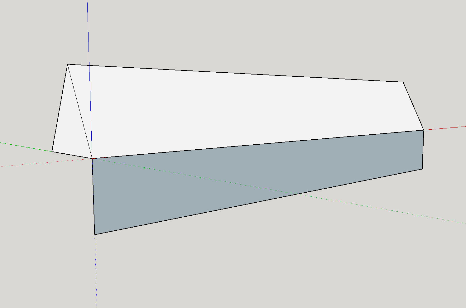
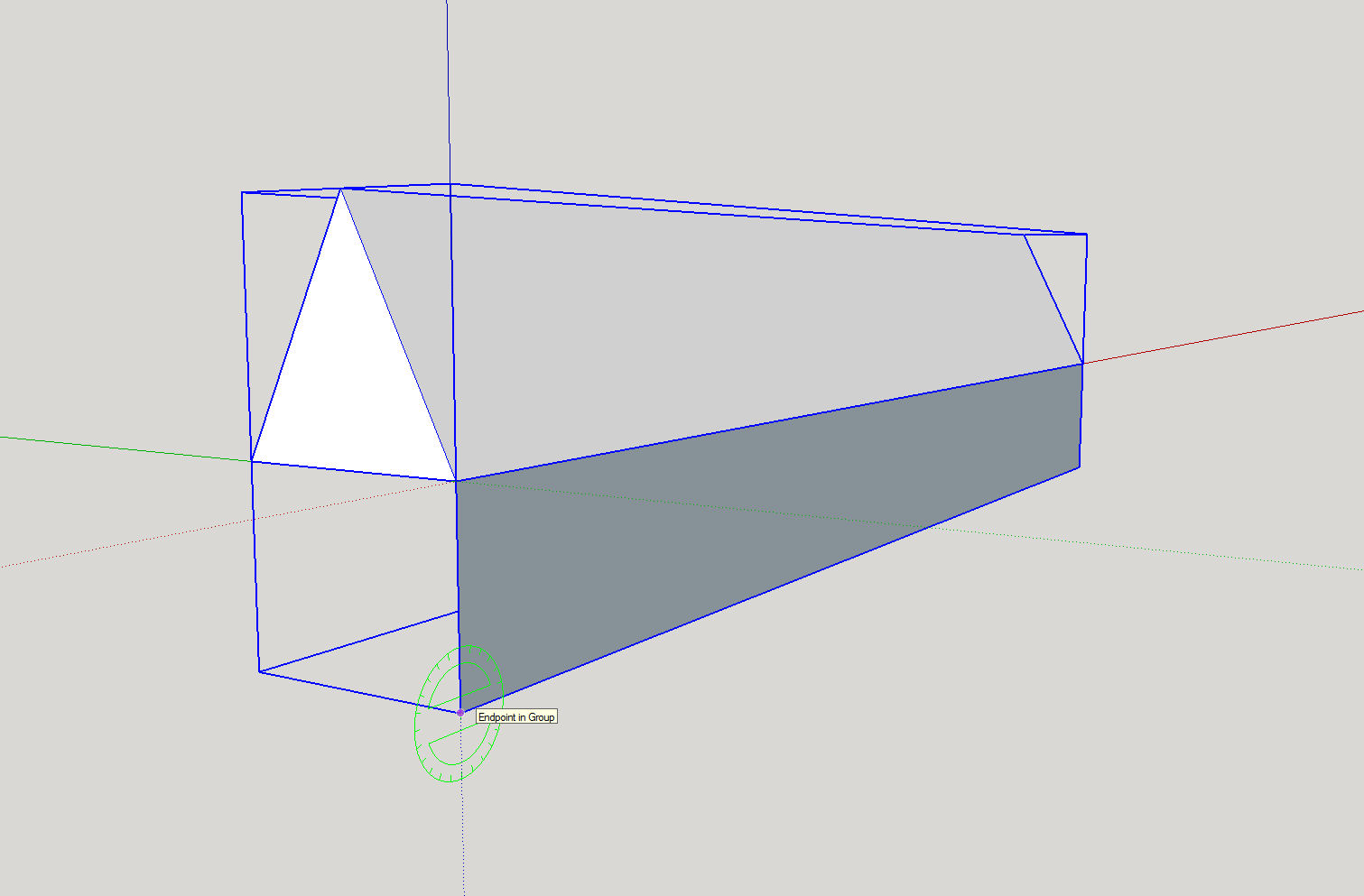
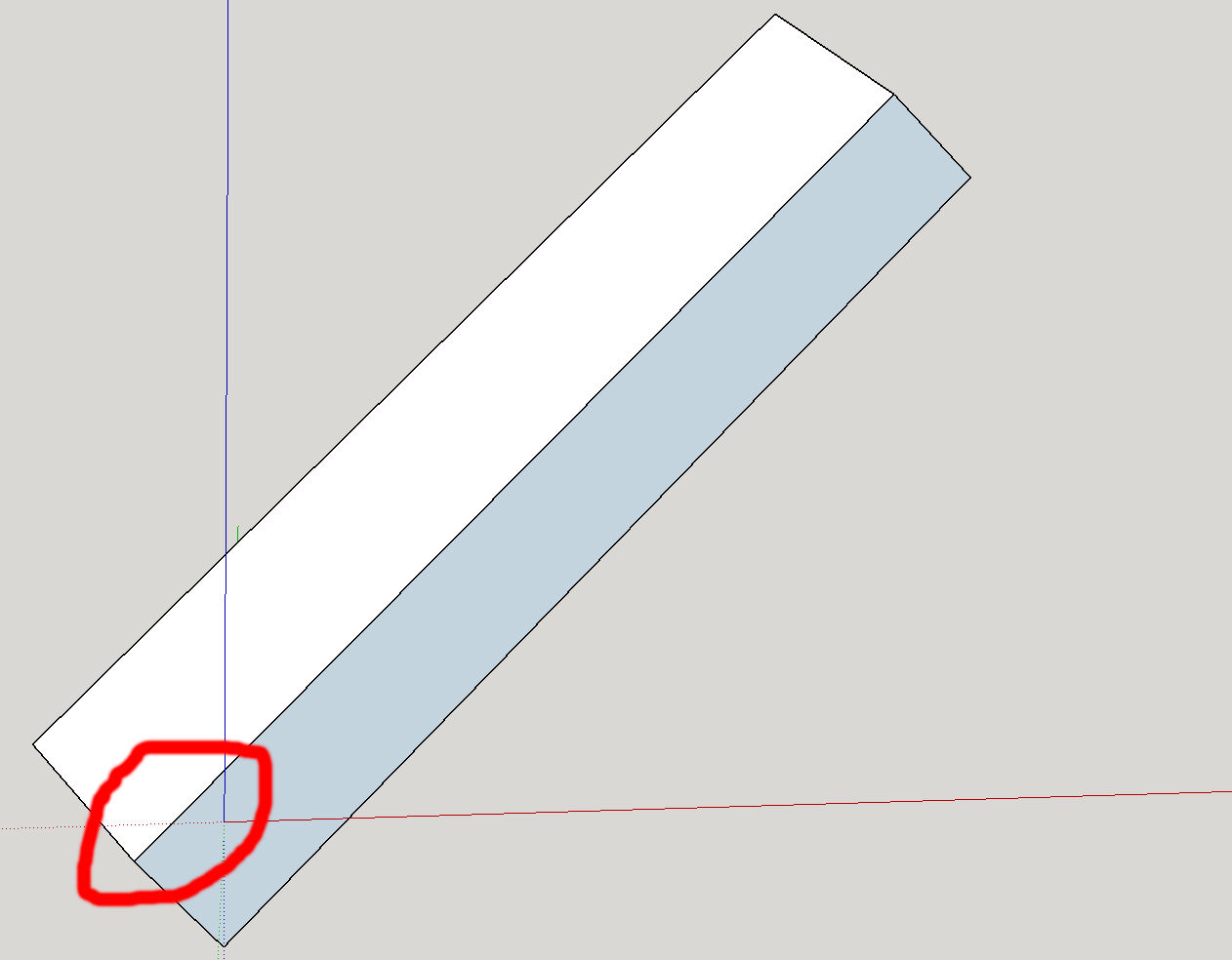
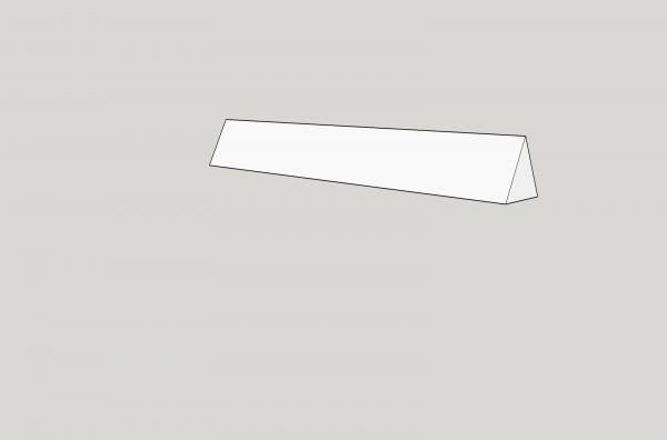
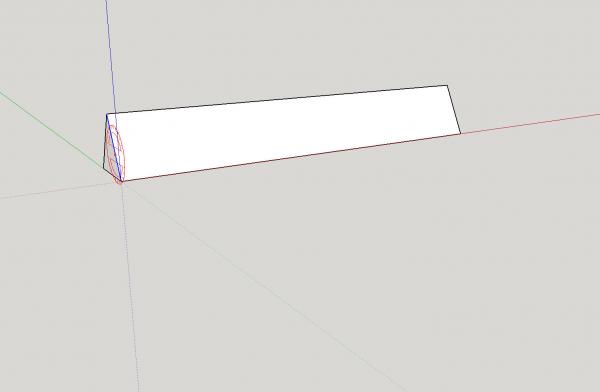
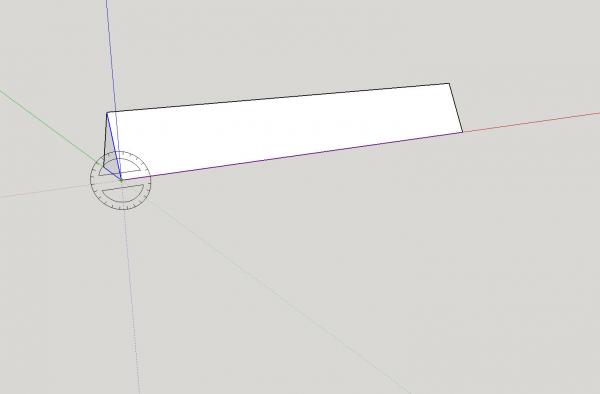
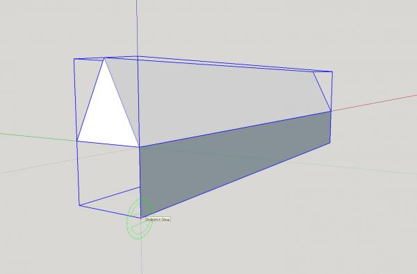
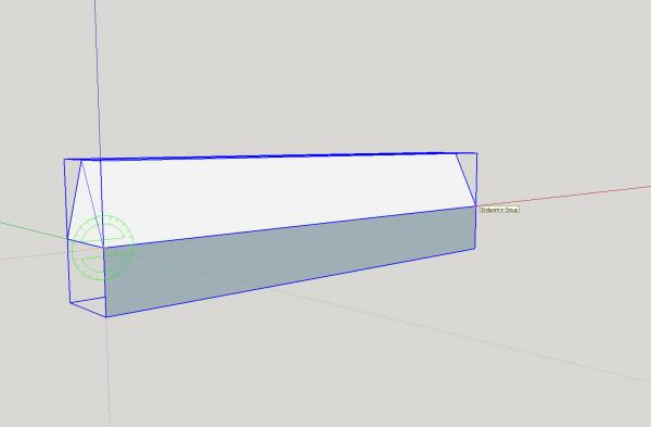
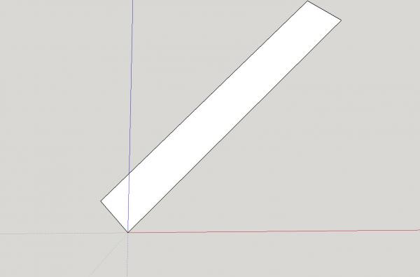
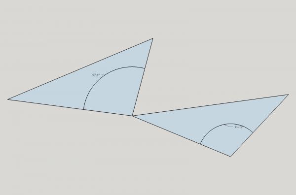
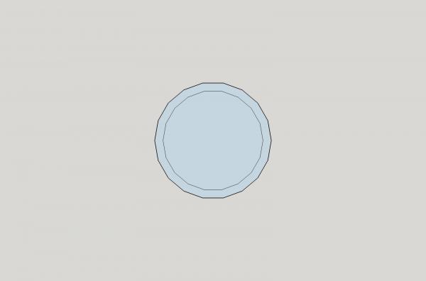
Part 14A I was doing some drawing on the 1/64th scale version of the dredge frame, and I had to do a couple of operations that I have not covered, rotating an object, and copying parts between drawings. Rotating An Object The rotation operation in SketchUp can be almost impossible, if you do not have a flat surface to reference when attempting to perform this function. The rotate operation looks to be designed for architecture, where you have many flat surfaces to reference when doing the operation. If you do not have such a surface, SketchUp will pick an axis that it thinks you want to do the rotation in. Generally it will select the Blue axis, and whatever axis it chooses, it insists on, it will frequently stubbornly refuse to allow you to use another axis. For an example: We want to rotate the shape below 45 degrees CCW up the X axis (around the green axis). The program places the rotation axis everywhere but the X axis. Here it says rotate around Blue axis? Red axis? Here it is indicating rotation along the front face. The only way I have found to have it consistently allow me to use a specific axis, is to draw a rectangle along the axis I want to rotate around. Before drawing the rectangle, I make the object a group, so that I can easily delete the rectangle later. Then I make the object and rectangle a group, so that they can be rotated together. The rectangle does not have to touch the object, as long as it is grouped with it. Now, when I place the cursor on the rectangle, the green axis is chosen. After selecting the corner (as the rotation point), then selecting the other corner as the handle to use as a reference for rotating the group. I moved the reference point up (CCW rotation, and entered 45 in the box at the bottom to specify 45 degrees of rotation (see the highlighted area). Voila, the object is at 45 degrees! There is one possible problem, though. The left edge is no longer at the origin (see the highlighted area below) If we need the edge to still be at the origin. We need to select the point and handle at the edge where the object and rectangle meet. Then I ungrouped the rectangle and object, and deleted the rectangle.


-
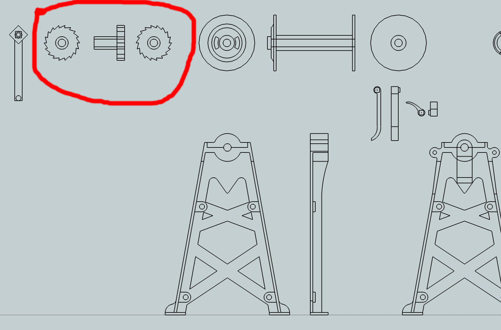
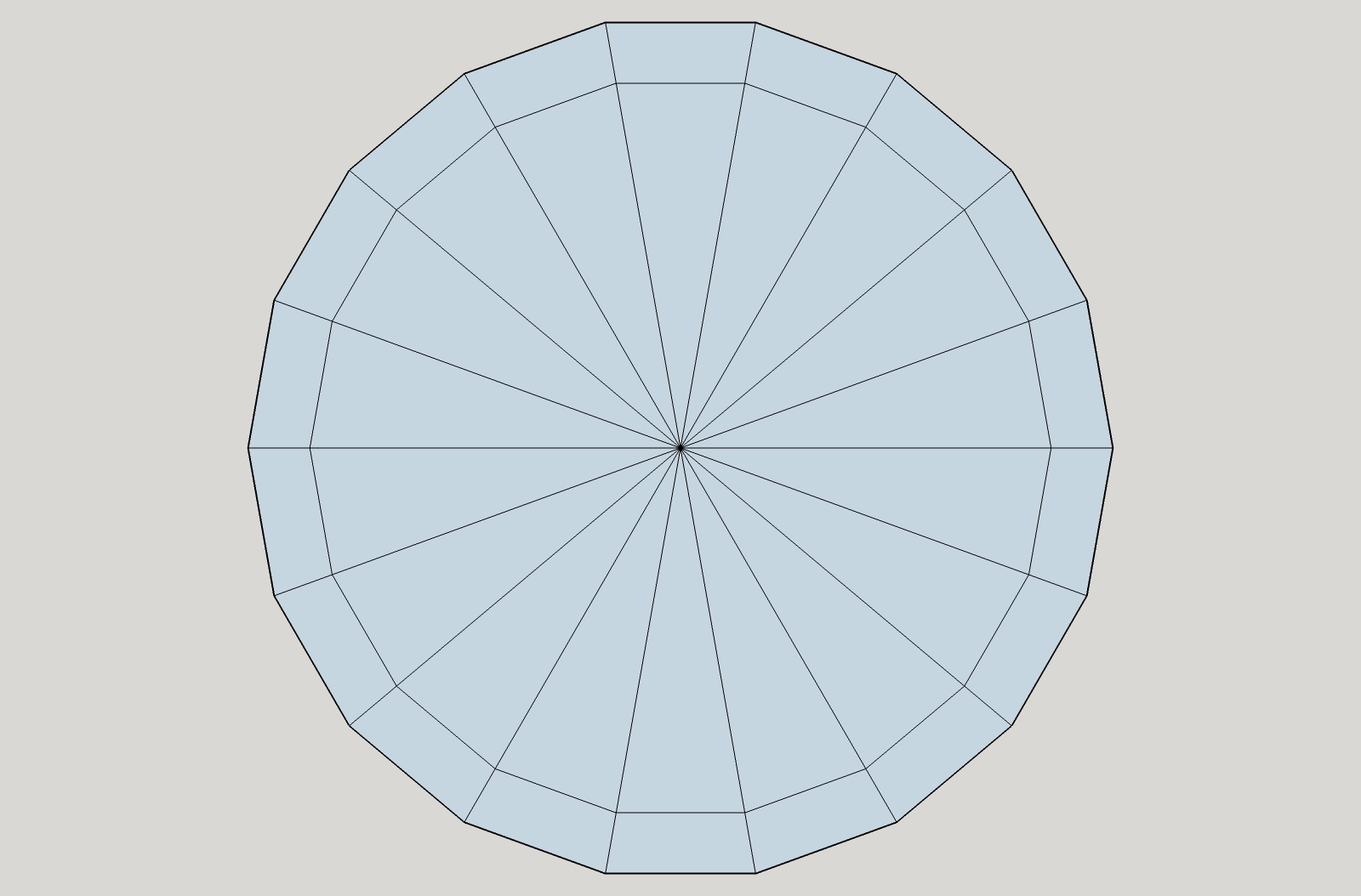
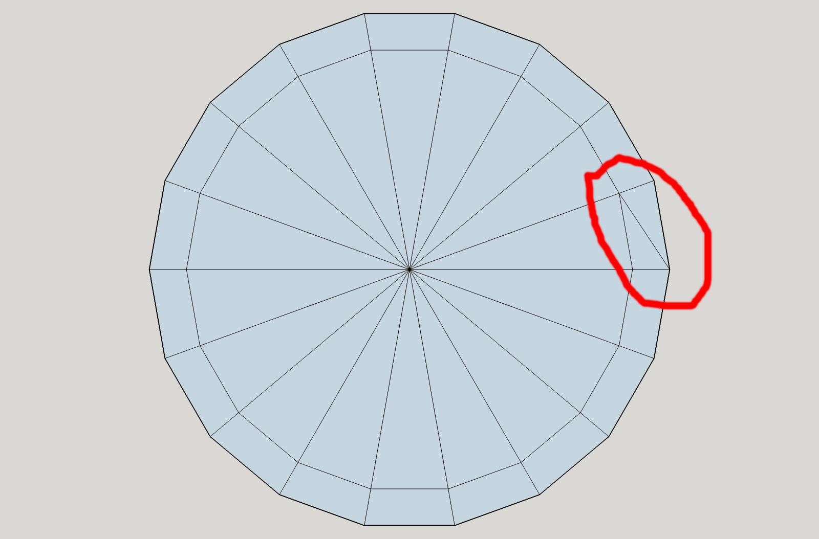
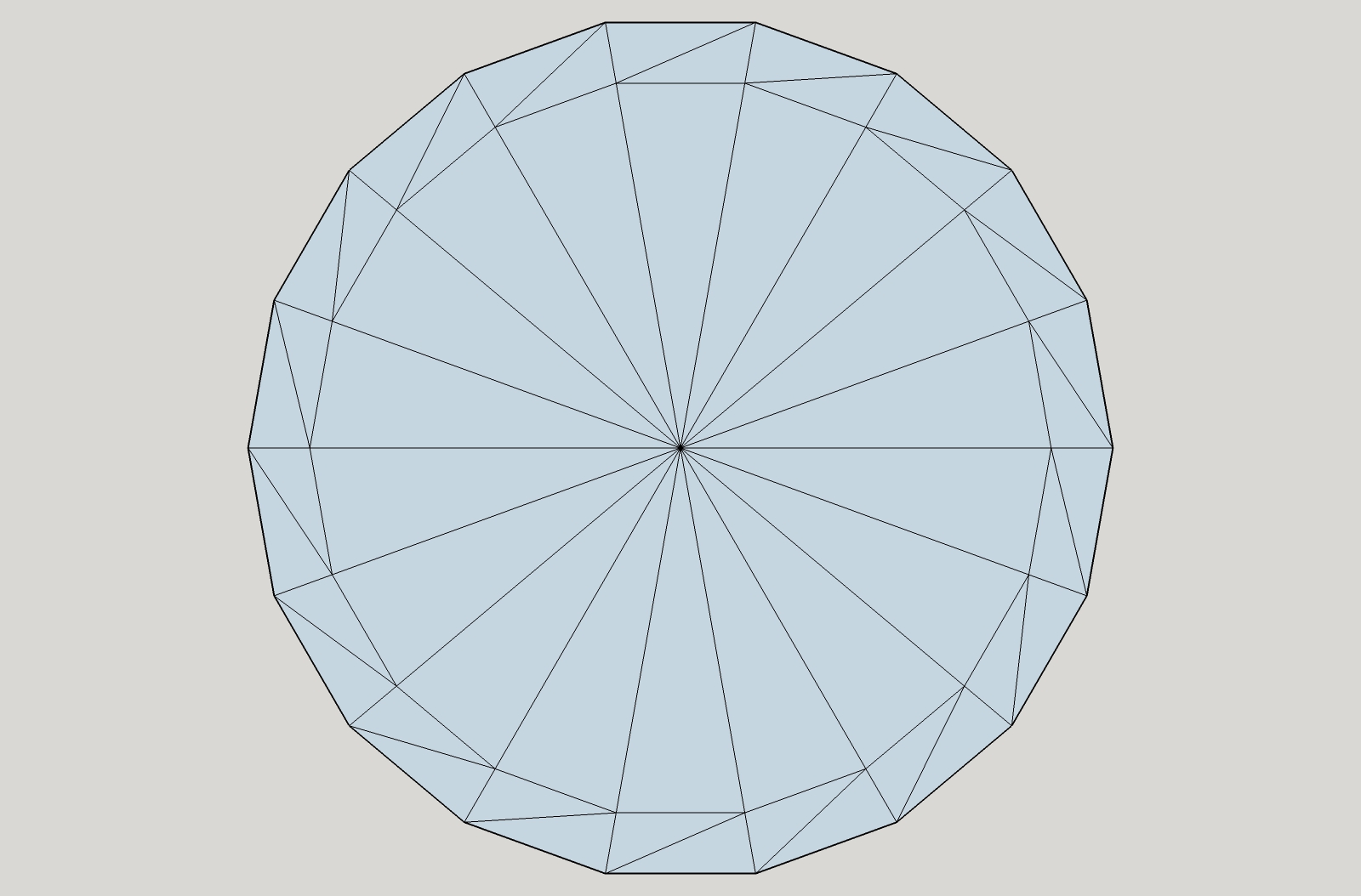
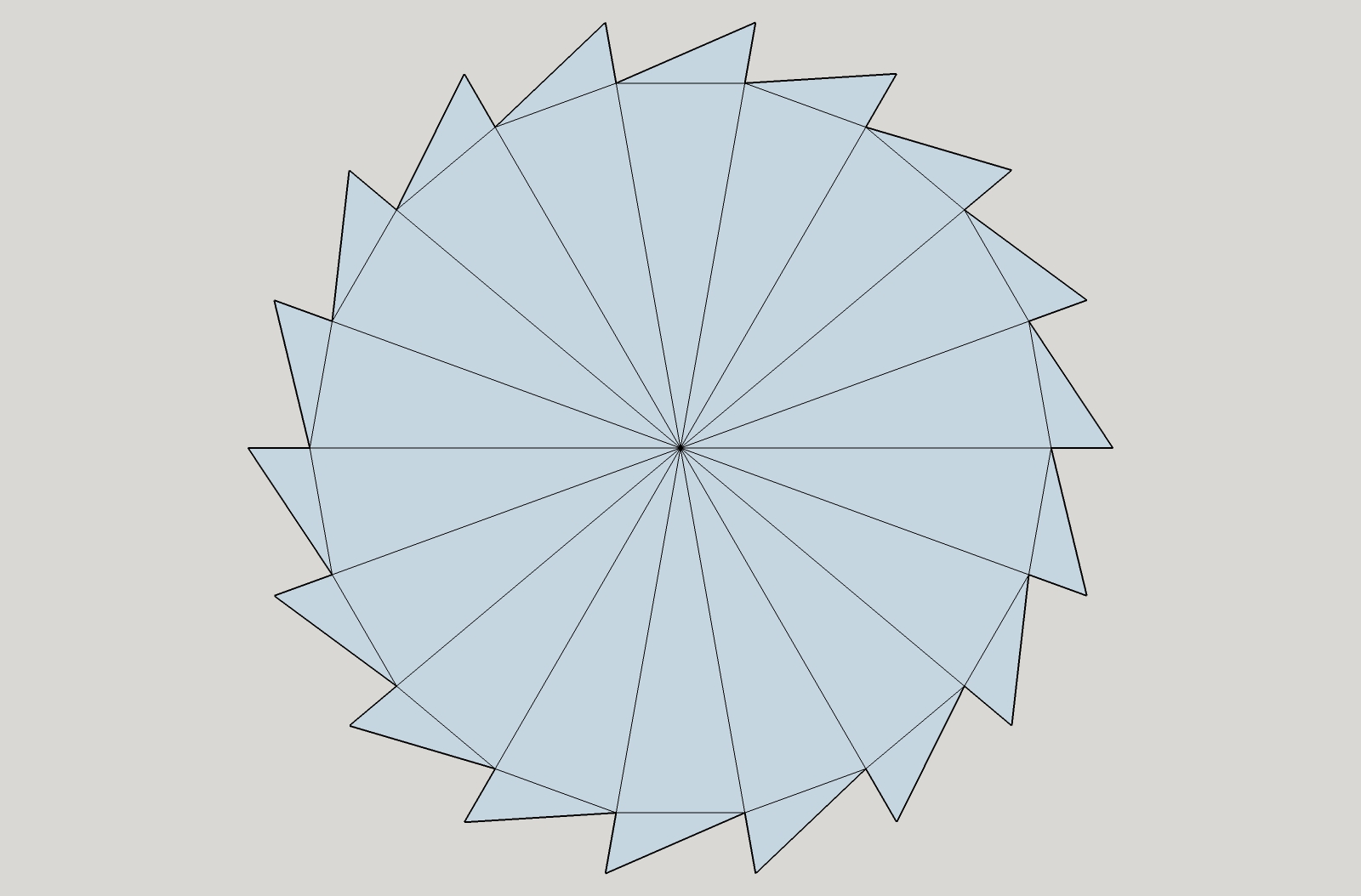
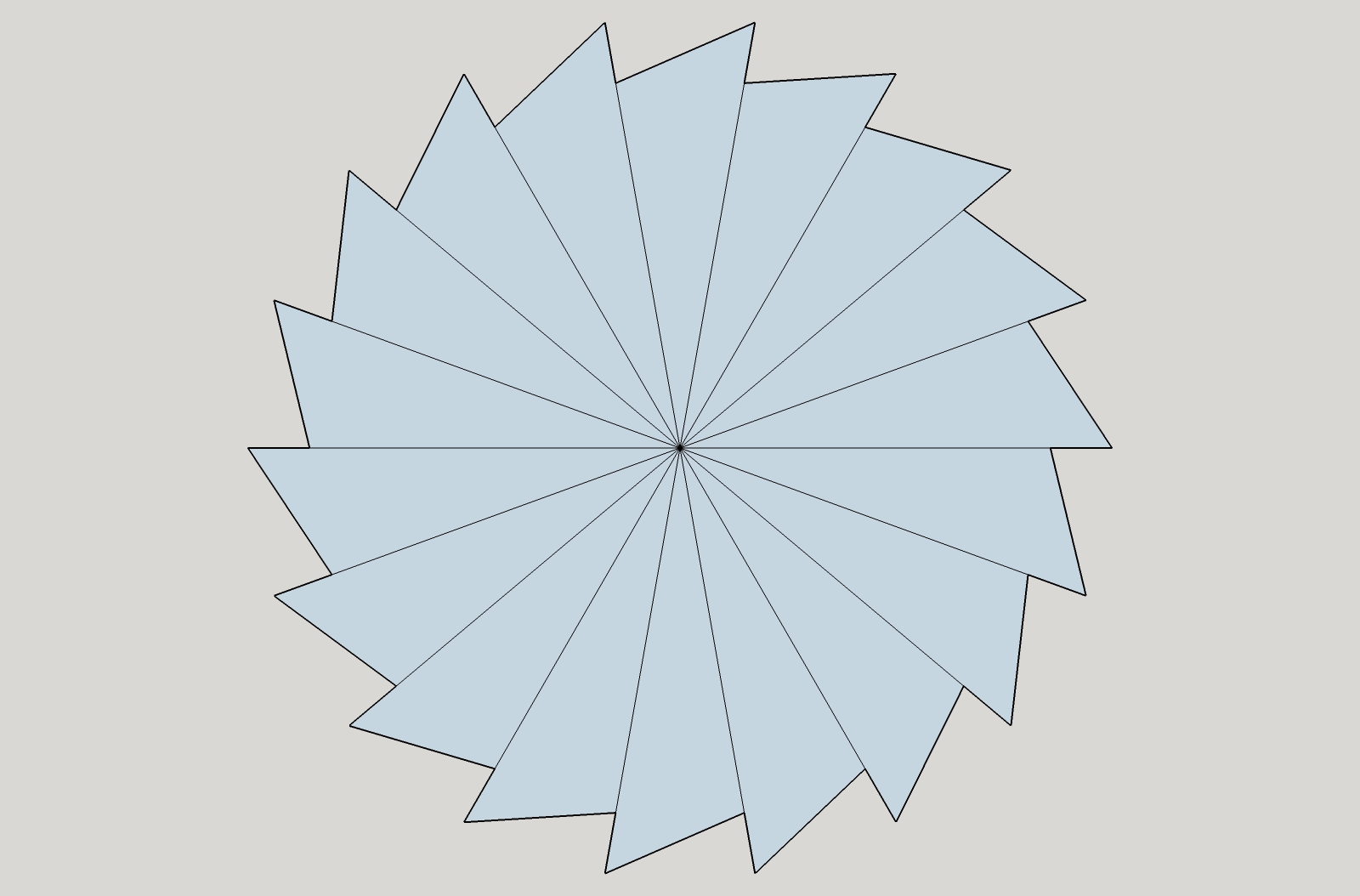
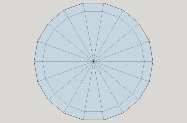
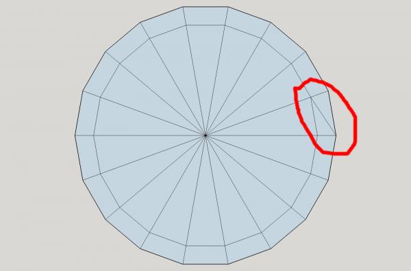
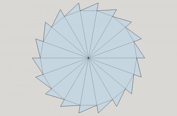
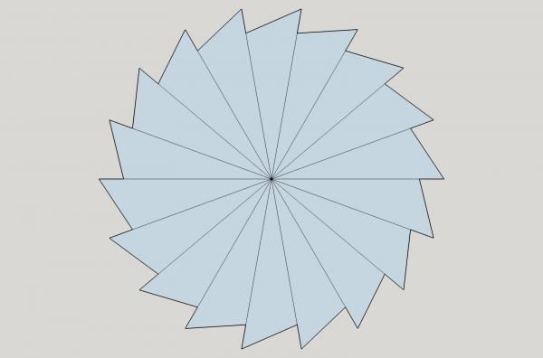
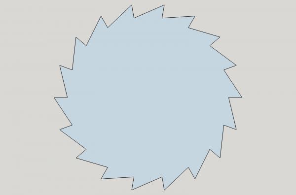
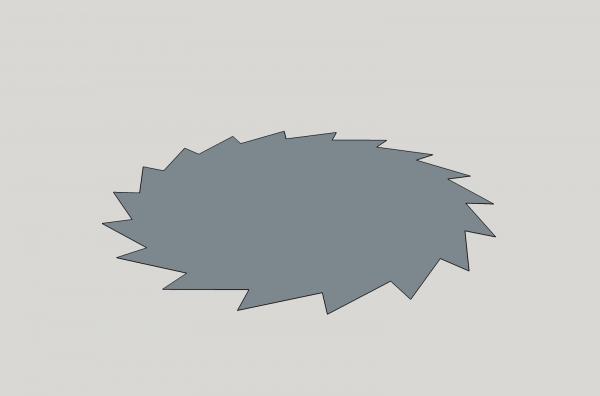
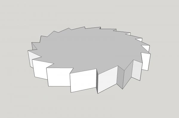
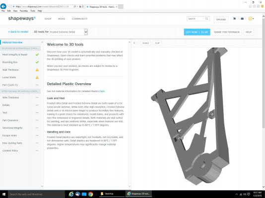
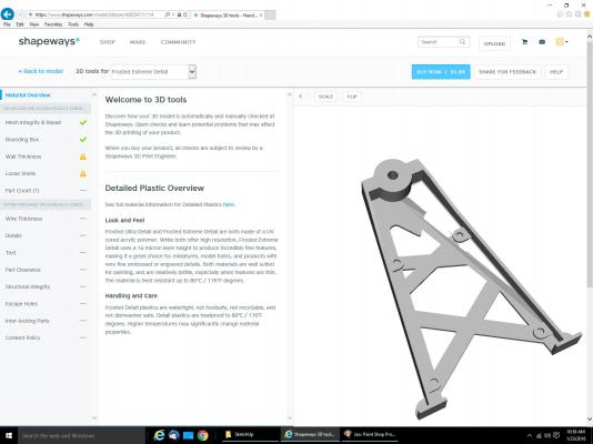
Part 13 I originally drew the Pawl Gear assembly with my CAD program, but here I’ll show how it can be done with SketchUp. In the CAD program the three standard views (front, side, and back) gear look like this. For the model, I simplified the tooth shape some, from what I think it would be shaped like in real life. I made the surface that the Pawl catches on close to a 90 degree angle (see left hand tooth shape). Basically as you will see shortly, I used the radial line as that side of the tooth. In real life that surface would likely be a bit deeper angle, to better hold the pawl in place when under pressure (see right hand tooth shape). In the model, you wouldn’t be able tell the difference, at least not without major magnification, and the nit picking type of personality that would. :-) SketchUp has no Polar Coordinate line draw capability, despite what the help file seems to indicate. The polar coordinates described, are for the Layout program, which is a feature of the Professional License version only, and this is a separate program from SketchUp. Polar coordinate lines, are ones drawn from a point, X long, and at Y degrees from and axis or another line. For example: “Draw a line from this point 10” long and at an angle of 20 degrees, from the X axis. SketchUp will however allow you to specify how many sides a circle has. The gear was drawn with 18 teeth. The pictures showed a gear of about this many teeth (as far as I could make out.), and I could have gone with 18 or 20. I used 18, simply because it was easier to draw, and more likely to print out correctly than a finer tooth size. I also assumed a ½” tooth height. So, I started by drawing two 18 sided circles, one the outer 7” diameter gear dimension, and an inner 6” circle representing the bottom of the tooth (1/2” tooth X 2 teeth, one on each “Side” of the gear). Next I drew lines from the center out to each of the circle vertices (endpoints that form the flat surfaces of the circle). To create the tooth shape I drew a line from each of the outer vertices to the next counter clockwise inner one. Be careful to make the teeth point in the correct direction! When I first extruded the gear, I accidentally used the bottom view (right hand gear drawing above) of the gear, rather than the front view. When I placed the central cylinder in, in the correct direction, my teeth were backwards, and had to go back and correct it, later. I then continued around the gear. Then I removed the extra lines. Using this I extruded the gear to the correct height. To draw the pawl gear, I placed the parts in position, and used the gear tooth surface as one end, and drew a couple curves, that did not interfere with the next tooth, when engaged, for the body of the pawl. I originally did this in my 2D CAD program, but couldn’t find the version of the drawing I did it on. These posts cover all the SketchUp tips I can think of. Next time I’ll take you through the downloading of the file to Shapeways, and after that I’ll show the program I use to check the drawing on my computer, before submitting it.

-
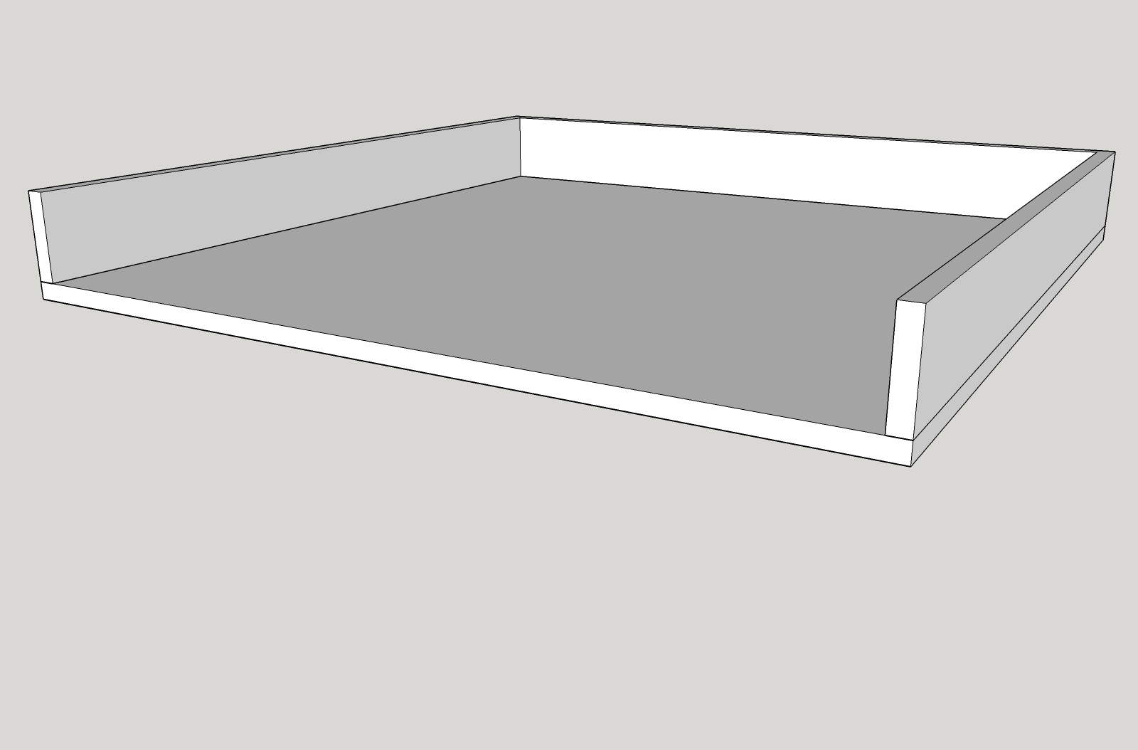
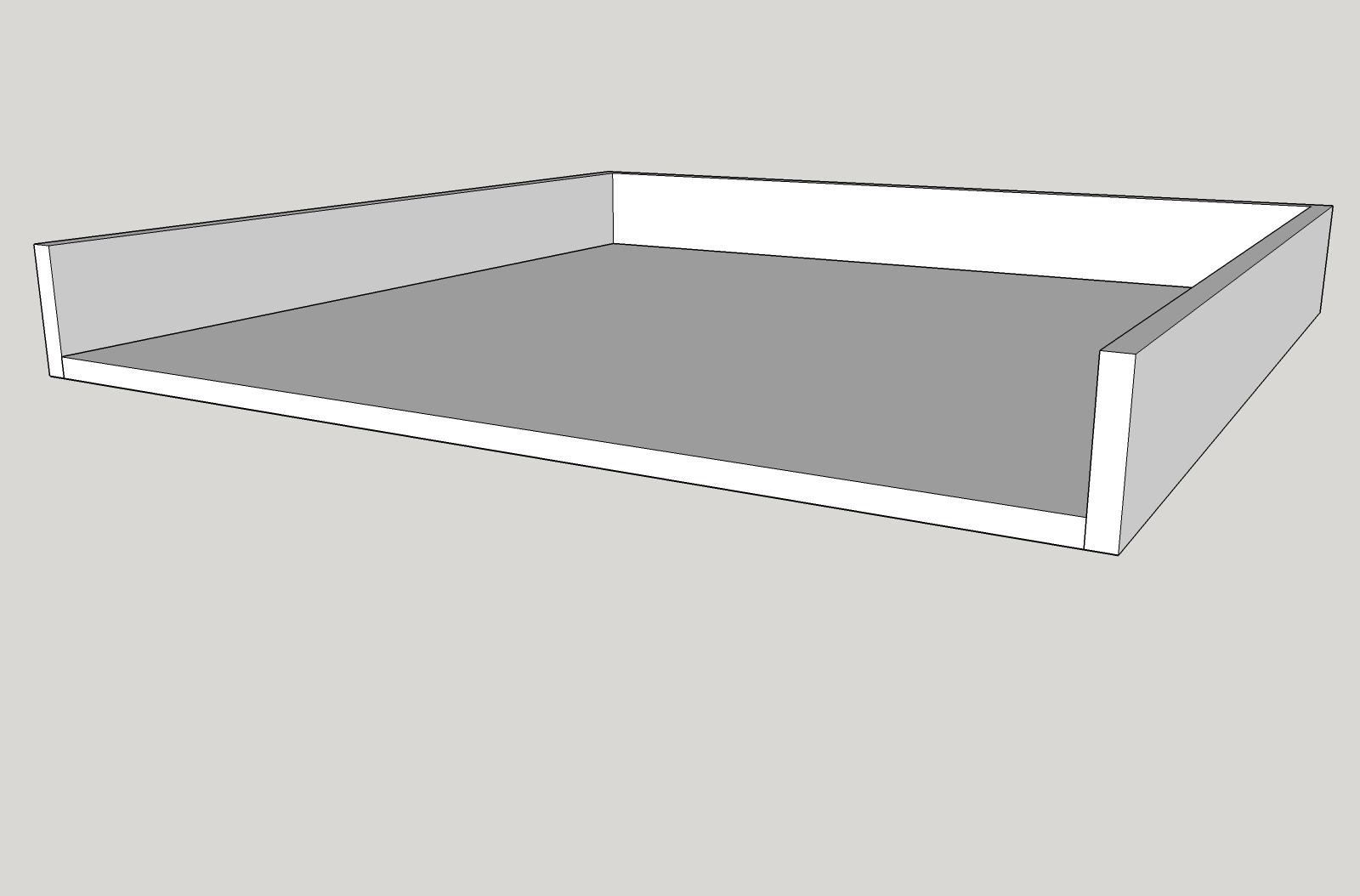
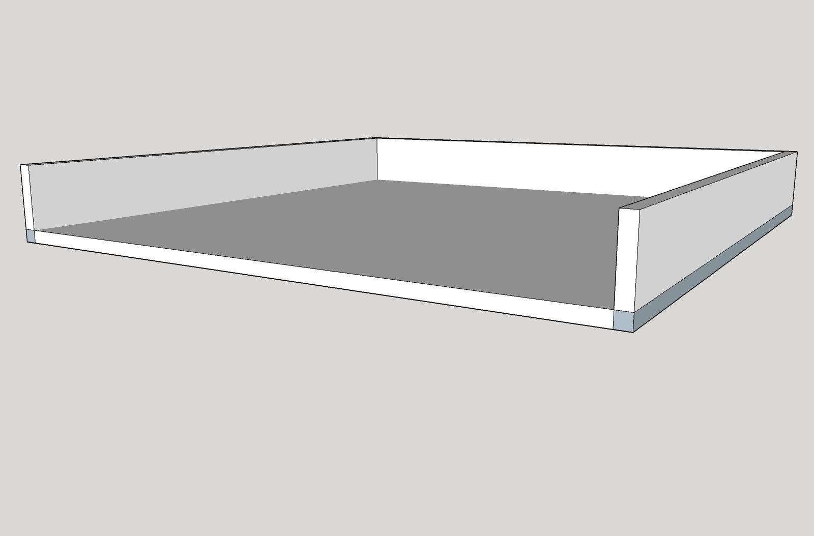
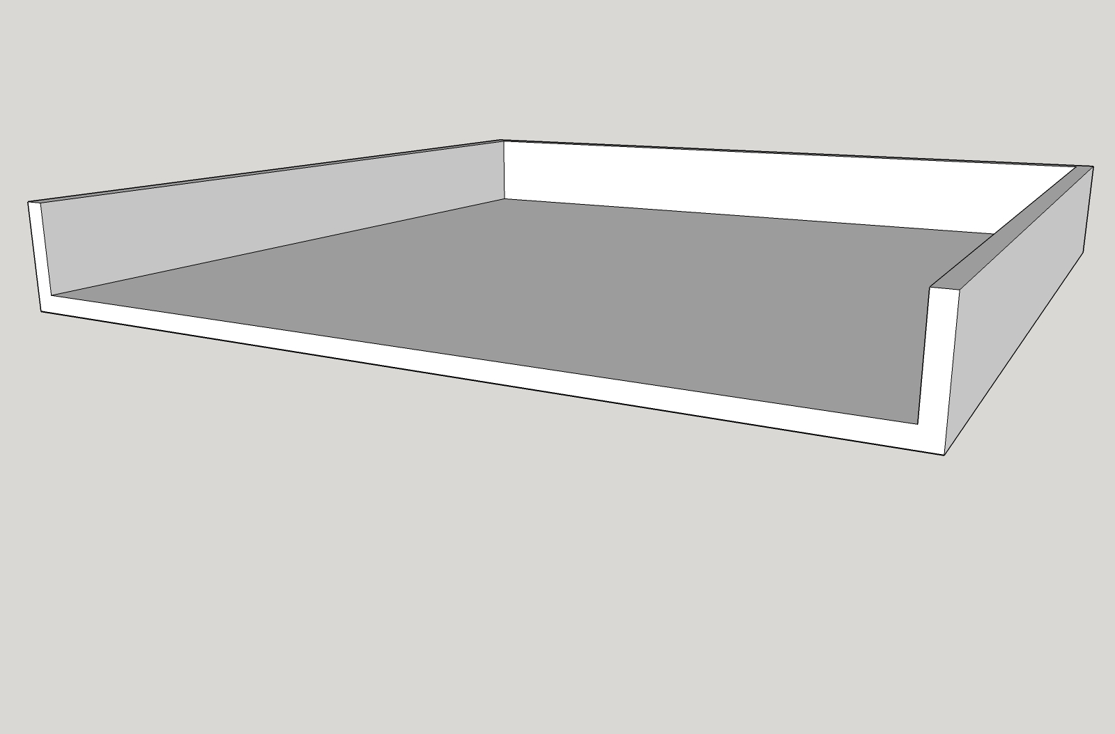
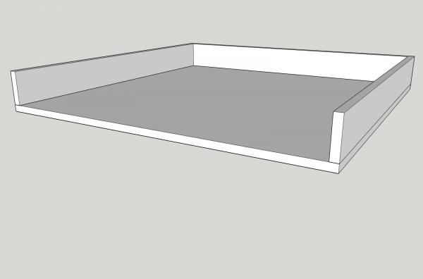
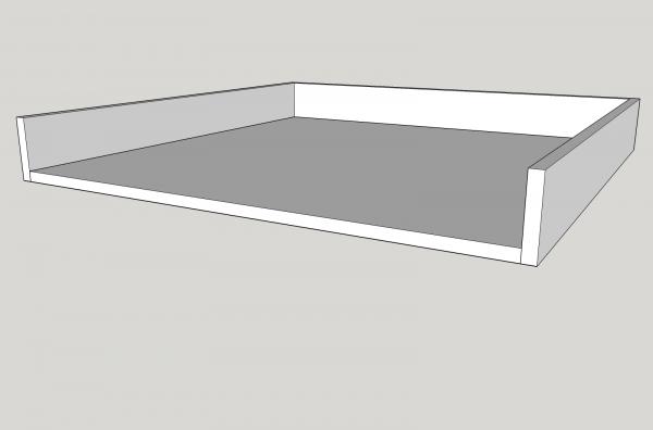
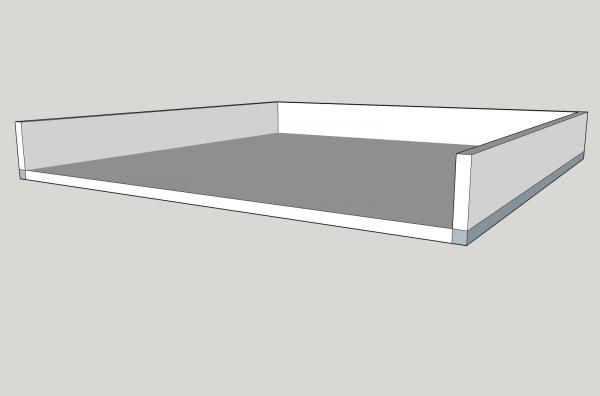
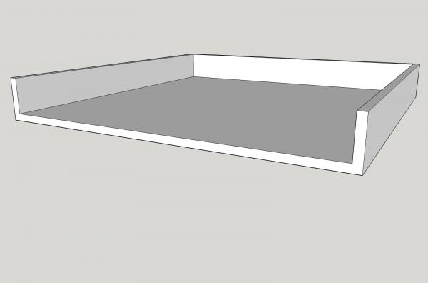
Part 12D There seems to be some confusion in what I meant by “overlapping parts”. I’ll show an example. We need an open top box 24” square by 3” high, with ½” thick base and sides. If we were making it out of wood, we could make it two different basic ways. There are several fancier ways that it could be made, but I’m going to stick to basics. I will be eliminating the front side, to show the joints better. The first way would be to cut the base 24” square and ½” thick, then nail on 2 ½” tall with ½” thick sides. The second way would be to cut the base 23” square and ½” thick, then nail on 3” tall sides with ½” thick sides. To draw this for 3D printing I can draw it 3 basic ways. The first two are just like I drew them above. The third way is to draw a 24” square base, ½” thick, then paste on 3” tall sides. This causes the base and sides to overlap at the edges, as shown by the darkened areas. Theoretically all three ways will produce the same 3D printed box, but the Shapeways software choked when my drawing with overlapping solids was submitted. The final 3D printed box would look like this.
-
I think for the next post, I will show how I drew the pawl gear.
-
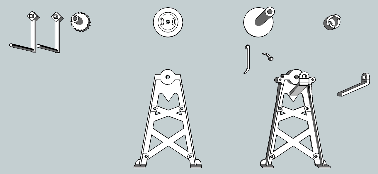
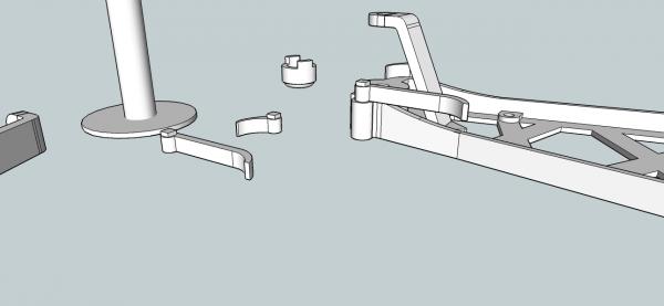
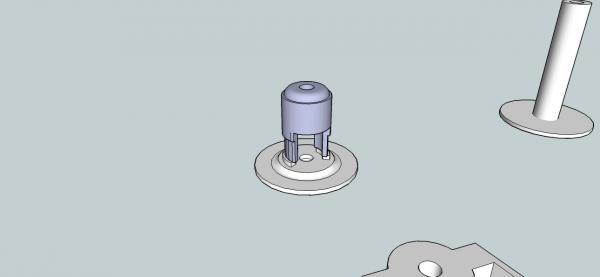
Part 12C The two handles were too small to print as separate parts, and attaching them to a sprue, would have left a lot of trimming to do on small parts. So I attached them directly to the leg. The pawl “handle” is positioned on the leg so that it correctly engages the Pawl Gear teeth, when the gear is installed. The clutch was also too small to print as a separate part, so I attached it to the left hand drum disk. I left a groove to guide the saw when I cut them apart. No matter how I drew the left hand drum disk, the Shapeways software deleted the center hole. I gave up and just put in a depression in the back for a drill guide, this depression the software left intact. I drew up a sprue of nuts, for detailing the final model. I also added small feet to the end of the crank handles, to stabilize them during printing, I’ll sand them off during construction..

-
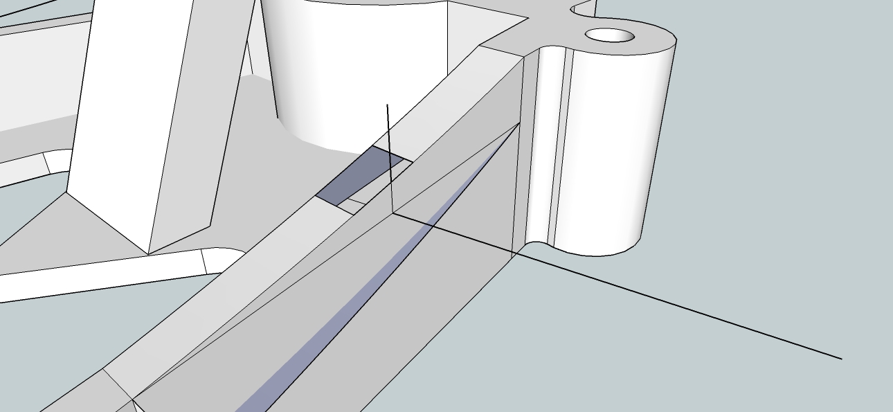
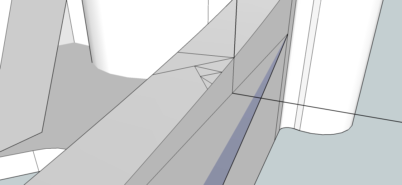
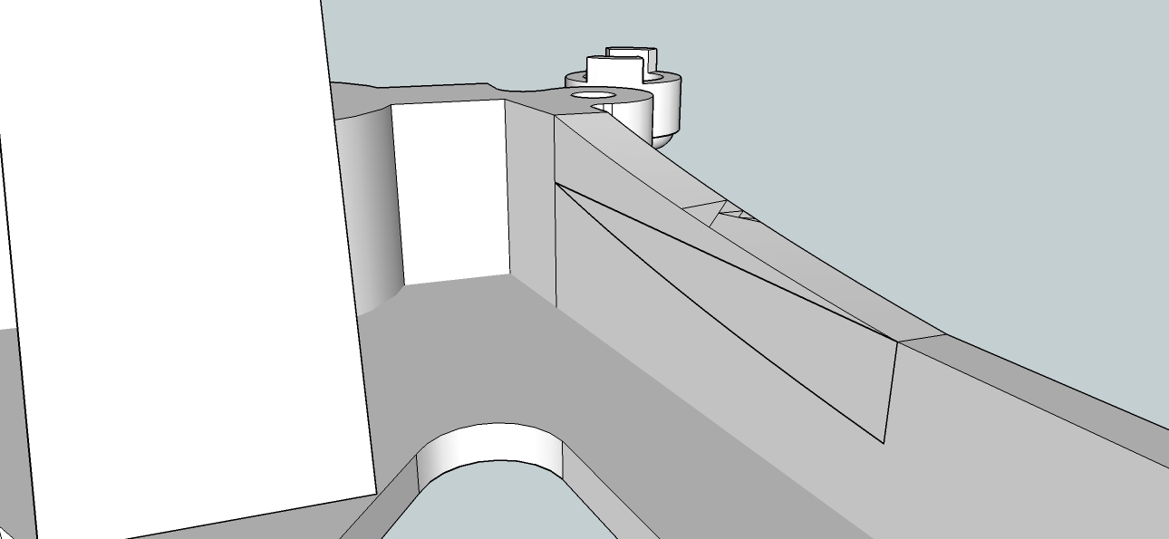
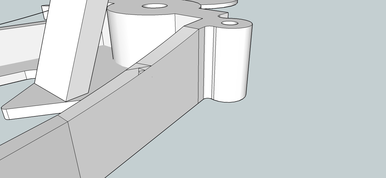
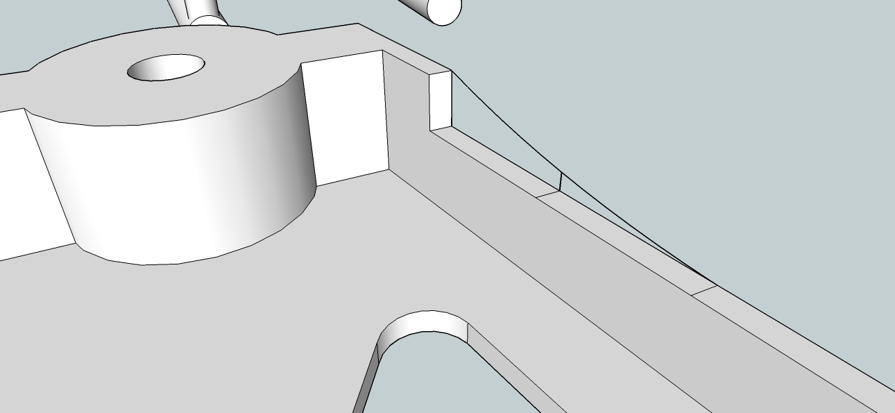
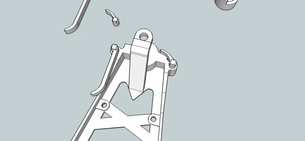
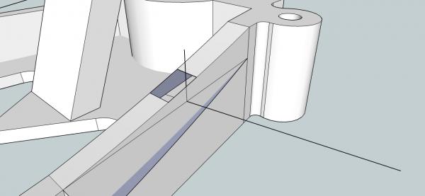
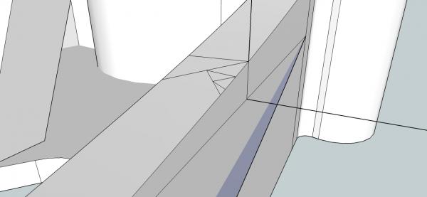
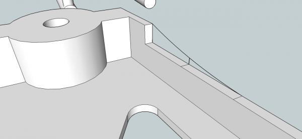
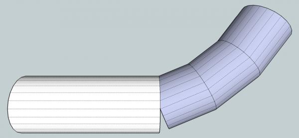
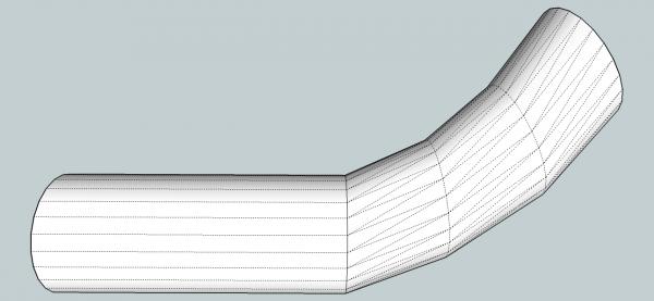
Part 12B The other leg is the one the handles mount to, and it has a more complex geometry. Where the vertical portion of the leg web meets the handle bosses, it widens at the transition. On the first leg it stayed the same thickness. On this leg the inside of the vertical web stays straight, and the outside angles off to widen the leg web. This complicates the shape of the extrusion, as the extrusion will stay the same width as the top, when created, making it wider than the leg web at the bottom. Because the inner surface stays straight, I drew the curved path line on that side. We can fix the extrusion shape later. After using the Upright Extrude, I had this. It matches the inside web surface, but sticks out at the bottom on the outside. We can delete the portion that sticks out, but first we must draw in a new curved line for the top outside edge. I deleted the outer wall, and drew a midpoint for the new curve, by drawing in a vertical line from the edge of the outside web top. Using the 3 point arc command, I drew in a new curved edge. When I erased the flash along the top, part of the curved surface was erased, along with the flash. I filled in the void using the triangle method discussed in a previous post. As you will see in later pictures, when I did this originally, I was lucky, and the curved surface did not need to be filled in. I finished cleaning up the excess flash and lines.


-
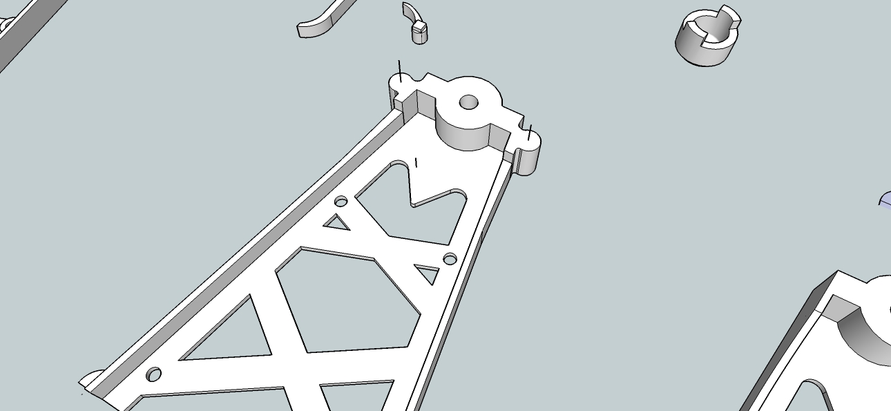
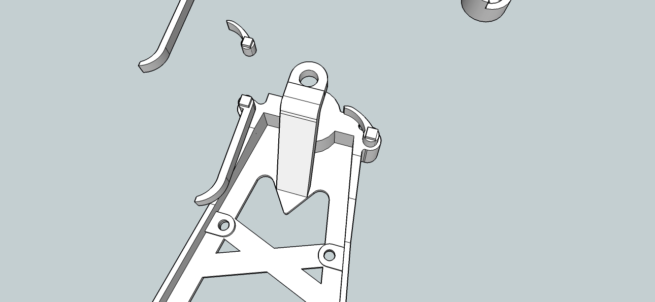
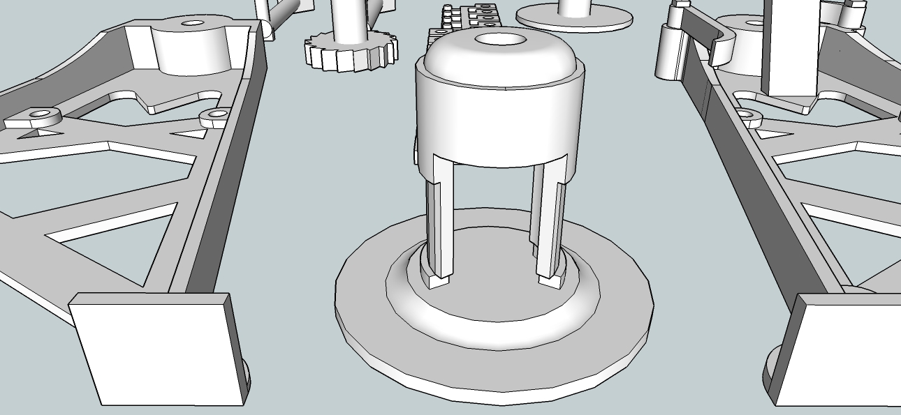
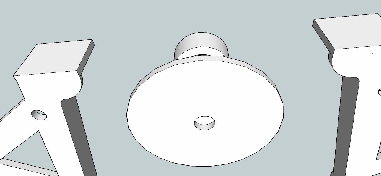
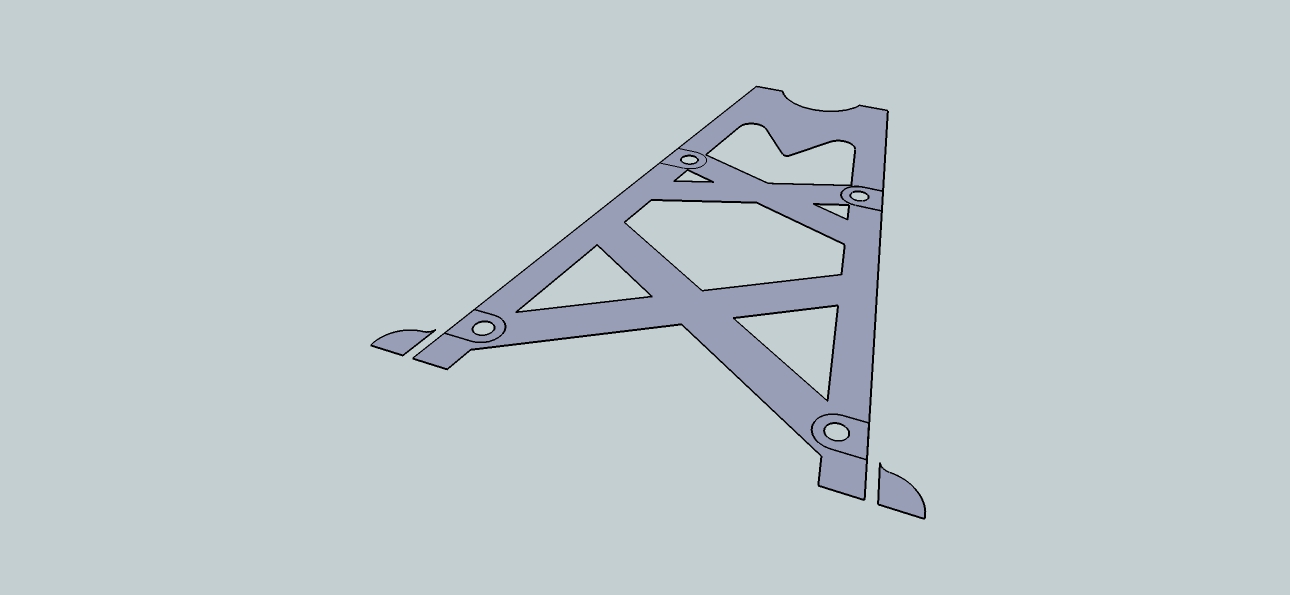
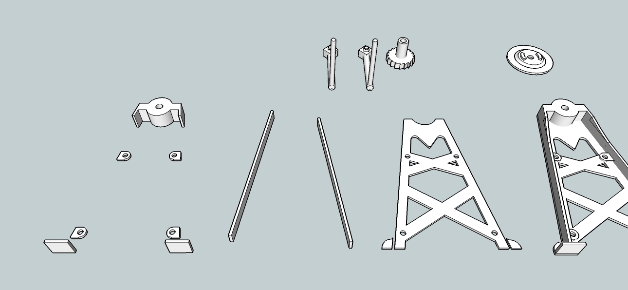
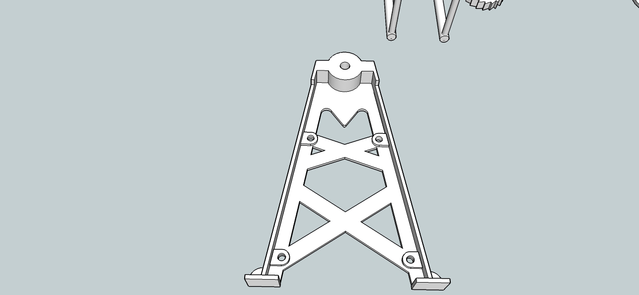
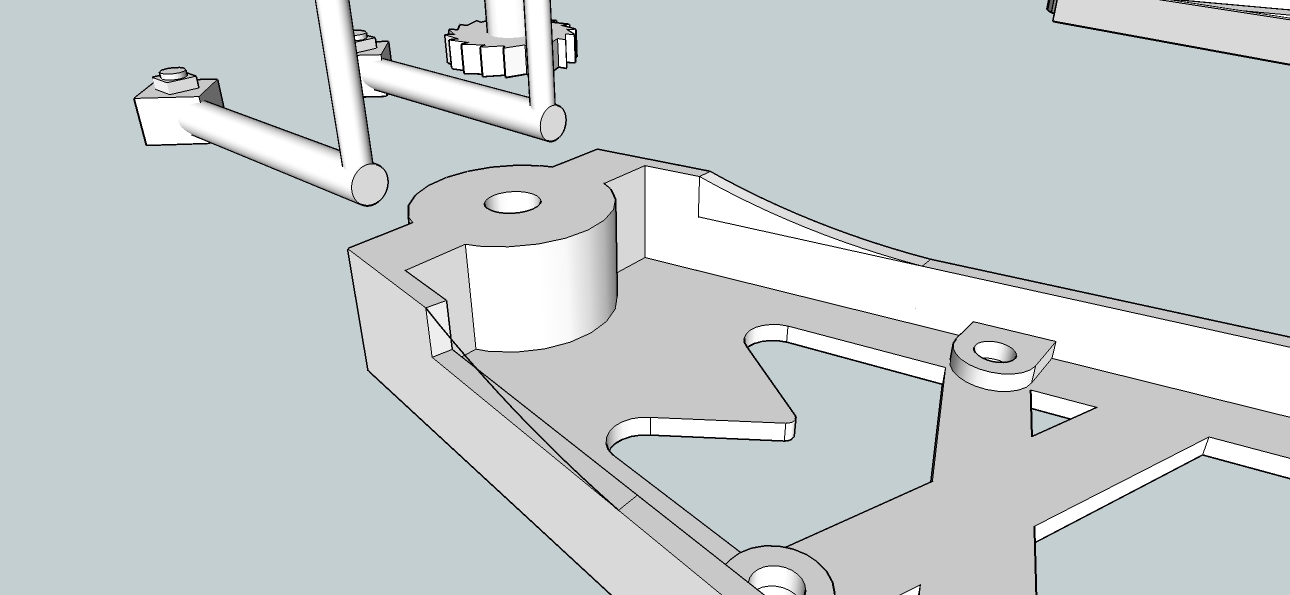
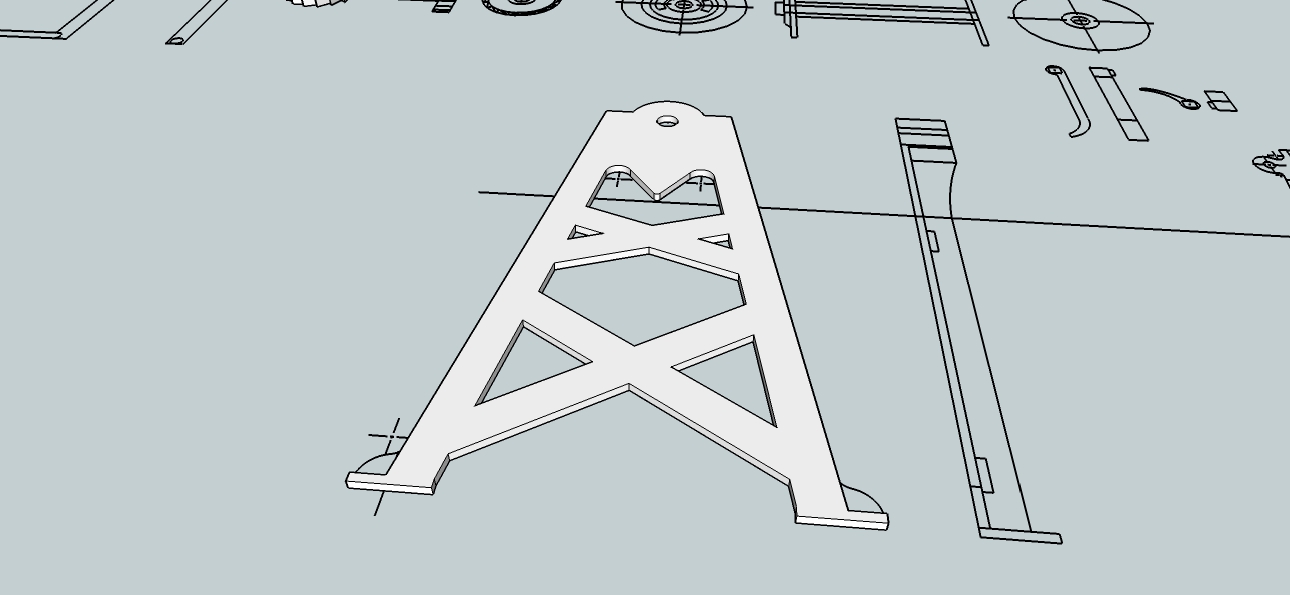
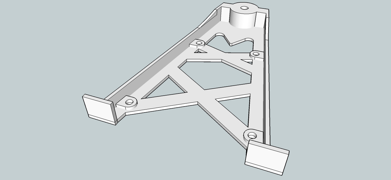
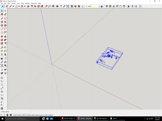
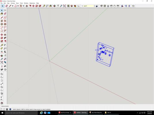
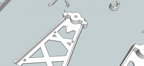
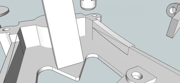
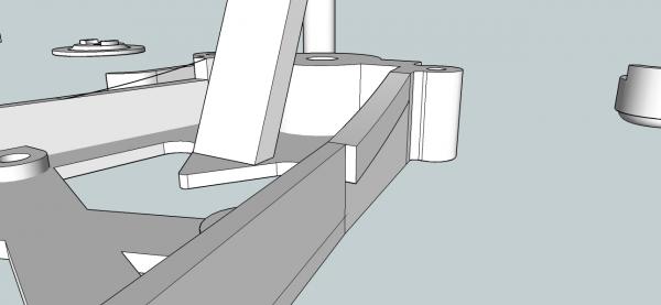
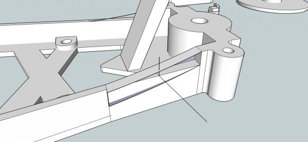
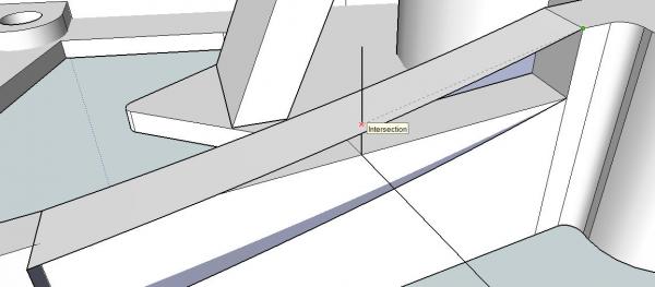
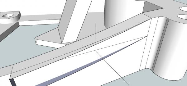
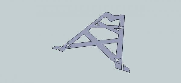
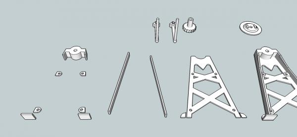
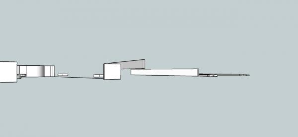
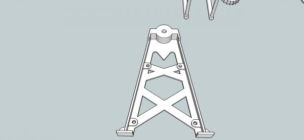
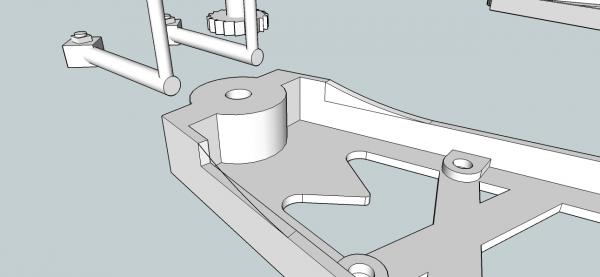
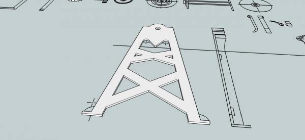
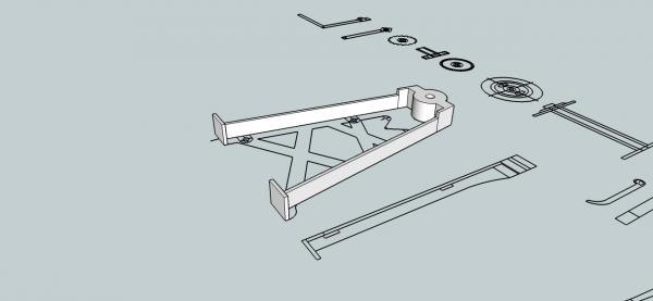
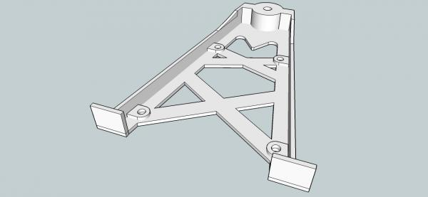
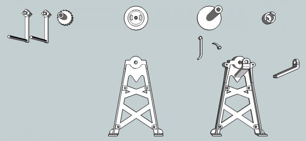
Part 12A Now we will switch to the hand dredge drawings and some problems I had, and examples of the procedures I used for some of the parts of the drawing. I started out Extruding the parts from the reference drawing to their full height, and the base to it’s full outline. Then I overlaid them to form the leg, ending up with this. In fact I had drawn almost all of the winch, before I bothered checking it at the Shapeways site. That was a mistake! I checked just the simple leg at this point, and it leg came out a mess. Drawing the leg with everything overlapping, was not the correct way to go! Not checking the drawing frequently was also a mistake. Even the holes in the legs for the support rods are partially filled in. The smaller parts came out OK, except that some of them were too small to print as separate parts. So I started over. I drew each major piece so that they did not overlap. First I drew the back of the web for the leg, drawing it so its outer rim was along the inner rim of the vertical portion of the web. Before I extruded this I deleted the outlines for the tabs, so that the center portion was all one solid. Then I copied it to another location, and deleted all but the outer outline. This makes sure the next parts will mate completely with the next subassembly. I then drew the vertical portions of the web, and the top support rod bosses and the feet separately, as can be seen in the left of the picture below. Here is a view from the side. Note, that the bosses are set at the correct elevation, to fit on top of the back web. The horizontal line is at the level of the bottom of the back web. Then, once again using copies of the originals, I combined them into one assembly. This leg is just about finished, but I need to add the angled section that ties the two levels of the vertical web together. This section has a curved profile, not a straight line slope, so it took a little more effort. After drawing in the proper length line to give me the correct position of the center of the curve, I drew in the curved line for one side of the transition. I used the 3-Point Arc command to do this. Then selecting both portions of the curve, then the rear vertical surface, I used the Follow Me command to draw in the section. Opps, the rear of the extrusion, does not meet the original starting surface. In this case it is off both in the vertical, and horizontal axis. The legs flair out as they go towards the feet, and this threw off the Follow Me command in the horizontal axis. Also the extrusion cut into the existing web, As the height remains the same as the solid is extruded. This is not a problem, as it is easily repaired. The Upright Extrude, will do the same thing. Here is a view from the other side. I redrew It using the Upright Extrude. Then I went in and erased the curved lines that are the bottom of the extrusion, to clean up the drawing. I repeated this for the other side.

-
Unfortunately, no. The only drawings I have of a modern winder, are from the Willie Bennett plans.
-
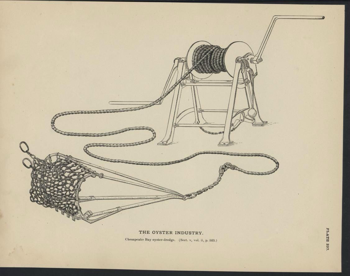
Kevin; I read the section in Chappelle's Small Craft book, on the skipjack "Messenger". The skipjacks with wells, did mount the winches on the main deck, according to Chappelle, just abaft the cabin. The crew stood in the well, and cranked it from there. So the shorter winch shown in the fisheries plate, would be correct for this type of skipjack.

-
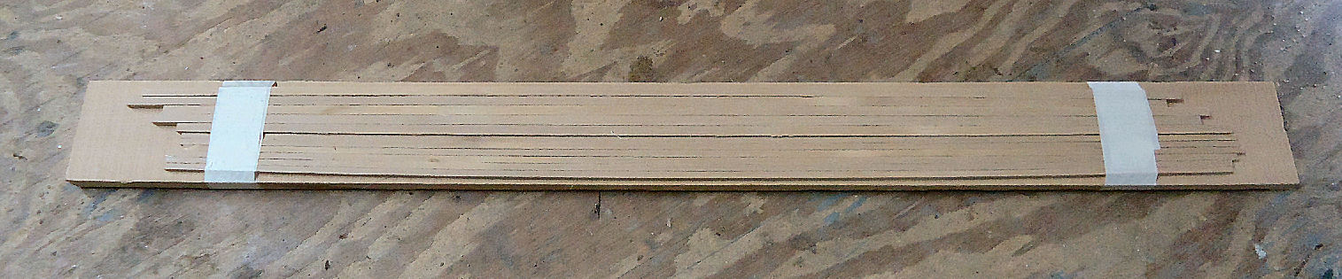
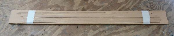
Here's a picture of the boxwood square stock for the mast and boom. The wood slab they are mounted on, is what I saw when I opened the end, thus thinking that the slab is what had been sent. The slab itself looks like a nice piece of wood. I wrote them and asked what type of wood it is. I'm going to leave the square stock attached, until I need one. The slab will be good protection, until I can build the wood storage rack.
-
As I get older, I must be losing neurons faster than I thought. When I got the wood order, it was wrapped up like the Fort Knox version of a mummy, so I only opened one end. What I thought was a chunk of a solid wood slab, was in fact the board they had mounted the wood strips on to protect them during shipment! Still have not managed to strip all the wrapping off of the shipment.
-
Well dang!! I got my boxwood today, but it is not what I wanted. I guess I did not make my order clear. What I need are 3/32 and 1/8 square stock, for the mast and boom. What they sent was a very nice solid chunk of boxwood, that I have no way to cut into the stock I need. I'm going to reorder when I can get a hold of them.
-
Part 11C Now I’ll do this again, but with the left hand extrusion vertical, as in the original curve setup. Follow me creates this new extrusion. Again the left hand end, is not in line with the original surface. Upright Extrude gives this. Notice that without the second extrusion to mate to, the right-hand end finishes at an angle not at a right angle to the last line.
-
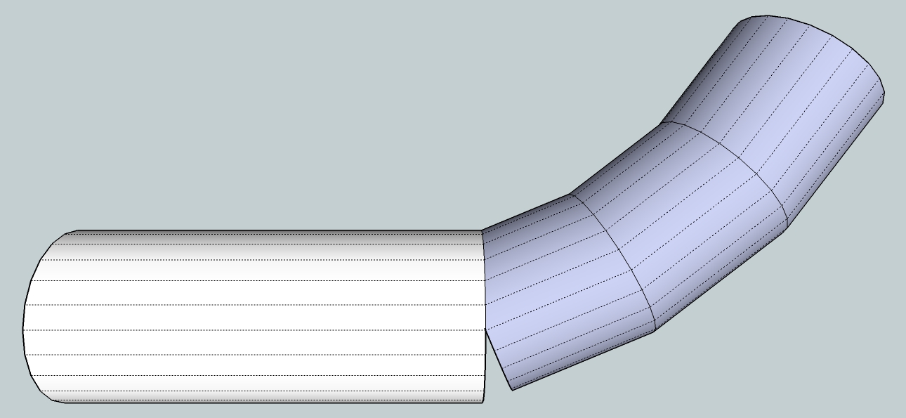
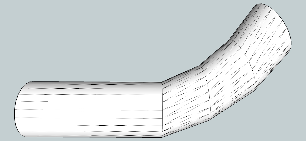
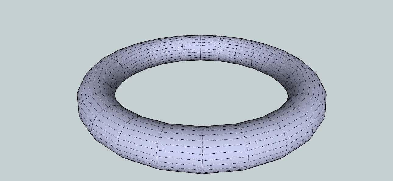
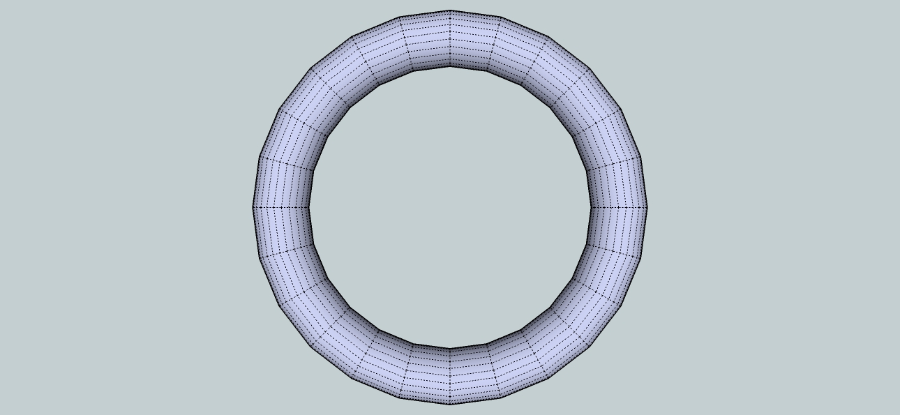
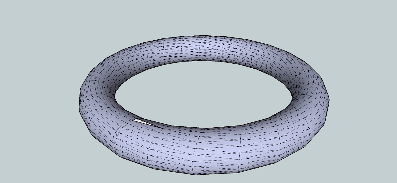
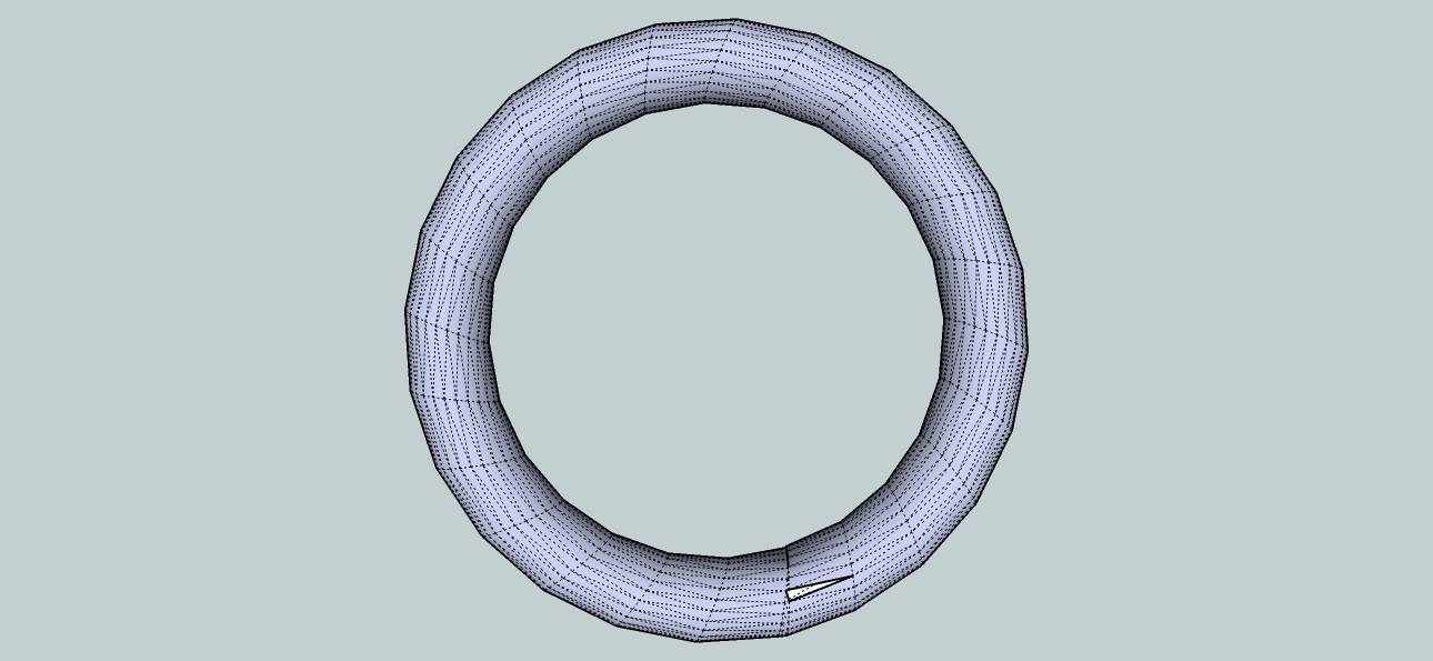
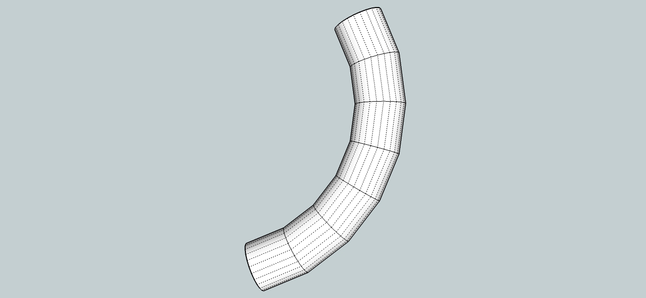
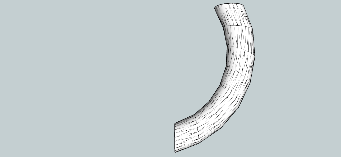
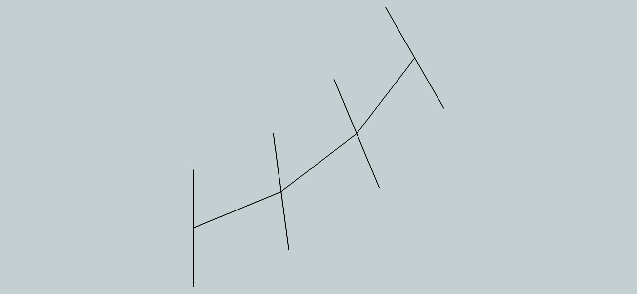
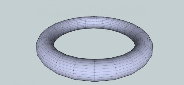
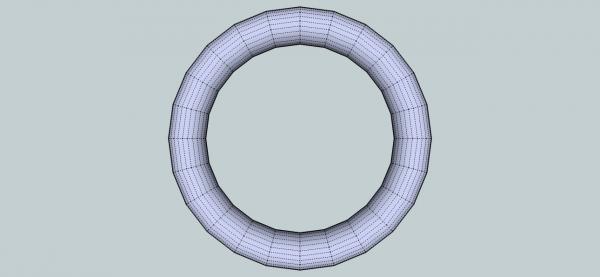
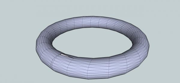
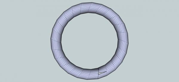
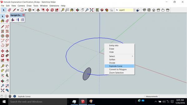
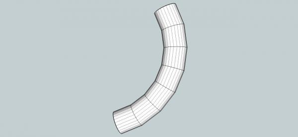
Part 11B Using Follow Me, gives the results below. The sections produced flow evenly along the path. The original surface is gone, if it were there, there should be a vertical joint, in the above view off to the right bottom, of the ring. The Upright Extruder produces this. The sections are fairly even, but titled at an angle to the path. Were the original surface was, there is a distorted section, filling in the ring, and a missing surface. The missing surface is not typical of this process, but does pop up now and then, as explained in previous posts. Let’s take a closer look at how the curved extrusions are created. First a tip. If SketchUp makes a curved path that is all one piece and you only need a part of it, you can break up the curve into individual lines, then work on them separately. Select the curve, then right click on it. Select the Explode Curve option from the menu. The curve is now a set of lines, that you can edit individually. Now I’ll shorten the path, and we will look at how the two different extrude operations work. This is the Follow Me result. Once again the sections are even and align with the path, but there is a change in the position of the first (lower left) surface orientation. Remember that the surface we wanted to extrude was parallel to the green axis, but the first surface on the extrusion is angled away from the axis. The first and last faces have been set at right angles to the ends of the path, rather than starting with the original surface, a new one has been generated. The intermediate surfaces, have been set so as to split the angle between the lines, at the joints. The cross section of the extrusion is circular, however. The result of the Upright Extruder is shown below. The intermediate surfaces are at a different angle than for the Follow Me. The first surface, however is in line with the original surface. The last surface is also not at a right angle to the last line. This is a view of just the surfaces, like we saw for the Follow Me version, for comparison. The cross section of the extrusion, is also not quite circular. Next We’ll try to connect to extrusions that have the end surfaces aligned like the Follow Me uses (right angle to the end of the line. The Follow Me extrusion. Even Sections were created. Now the Upright Extrude. Interestingly, the Upright Extrude correctly connected the right hand end, even though it was not in the same plain, than just extruding the surfaces without the end extrusions to connect to. This will not be true if the angle is too different.


-
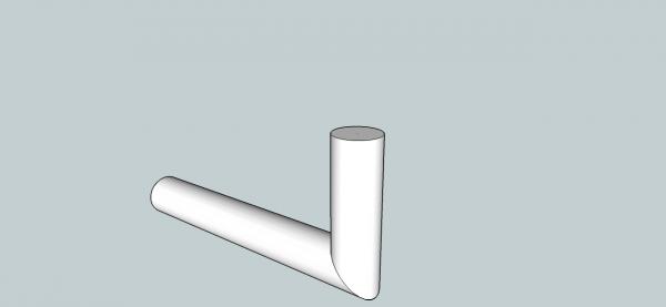
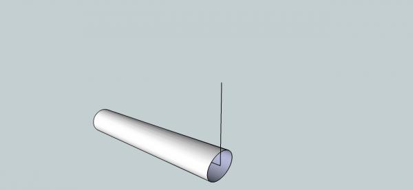
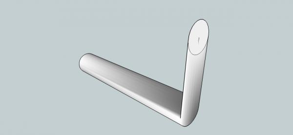
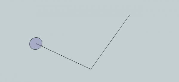
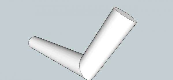
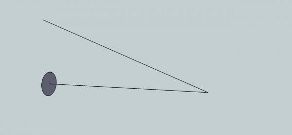
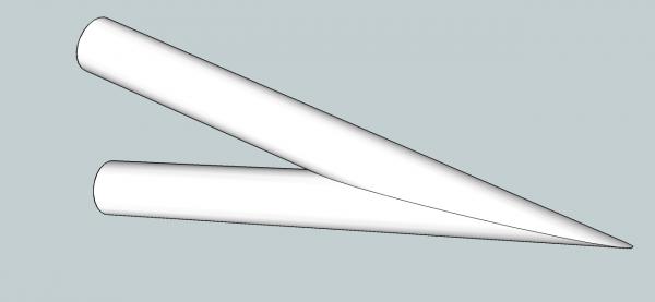
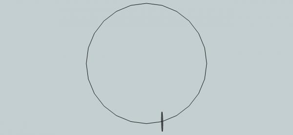
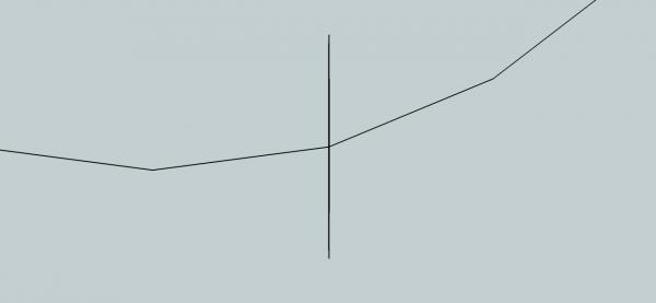
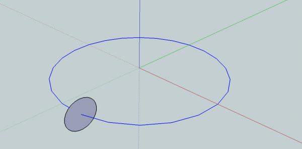
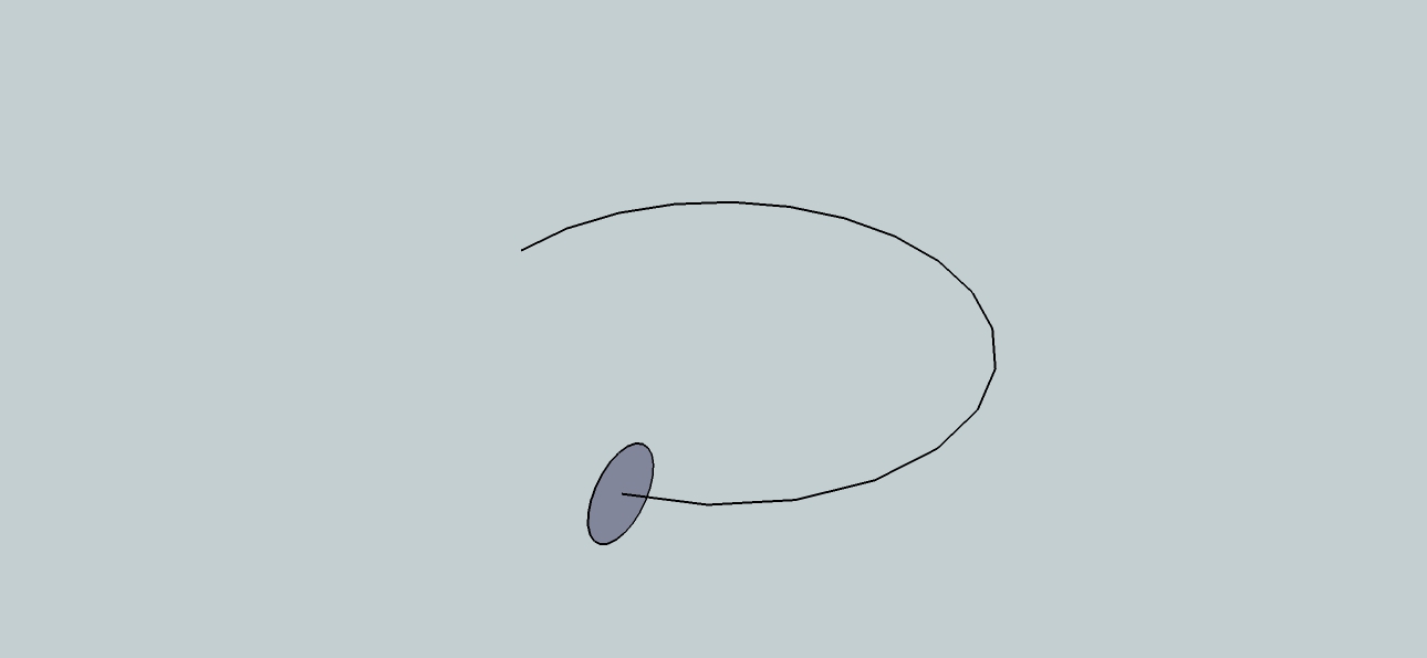
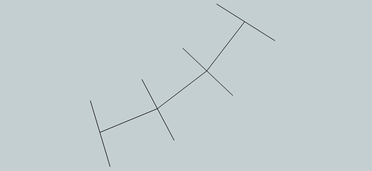
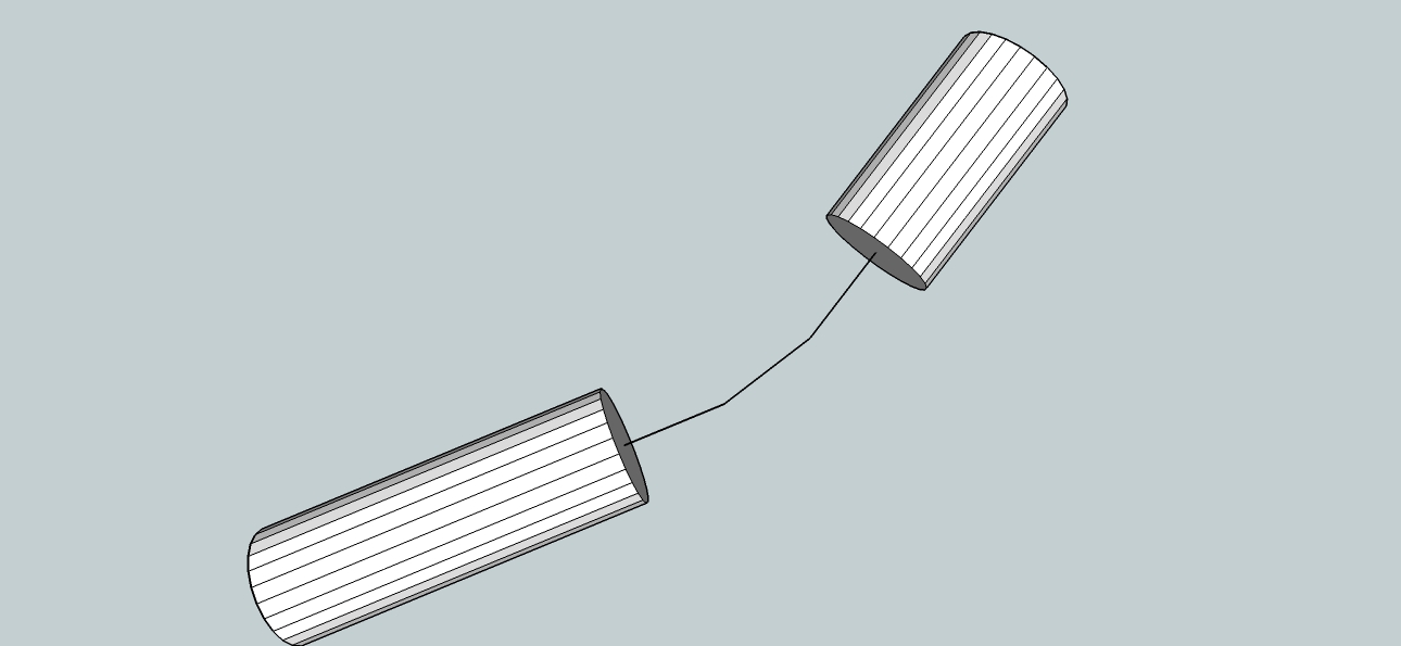
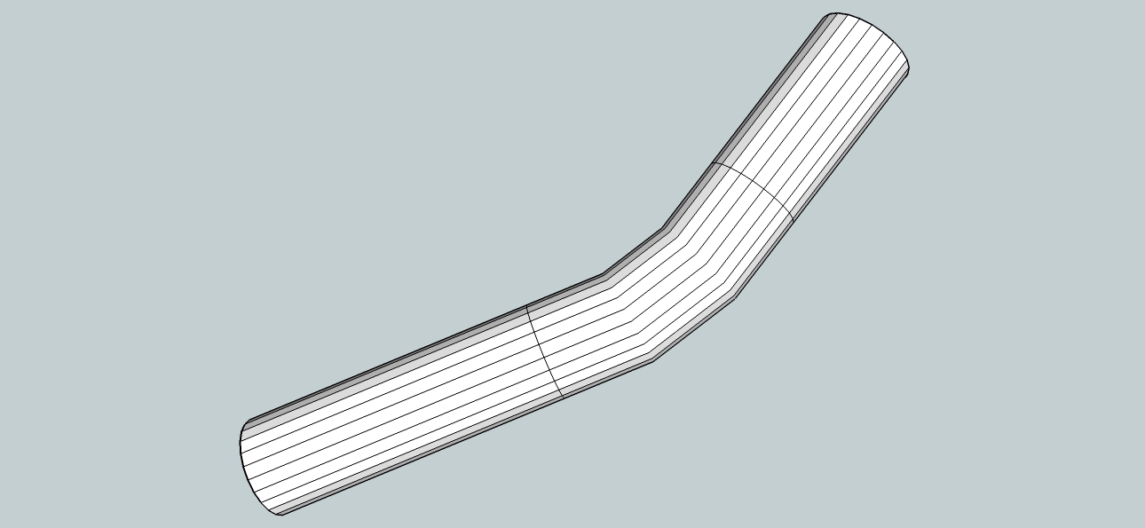
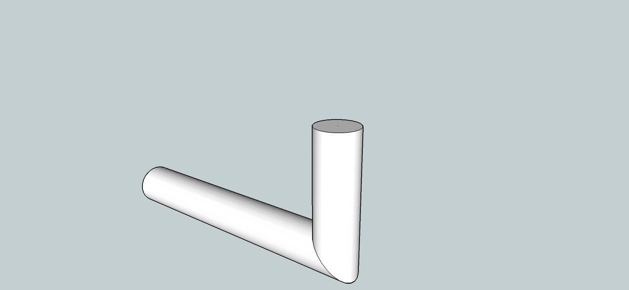
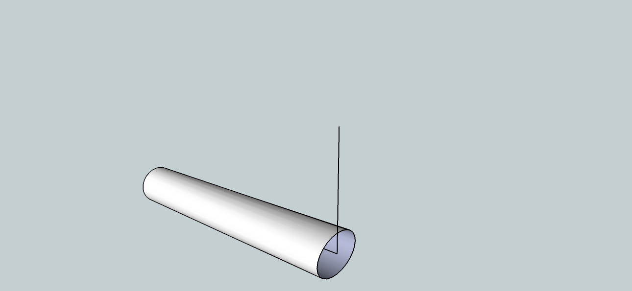
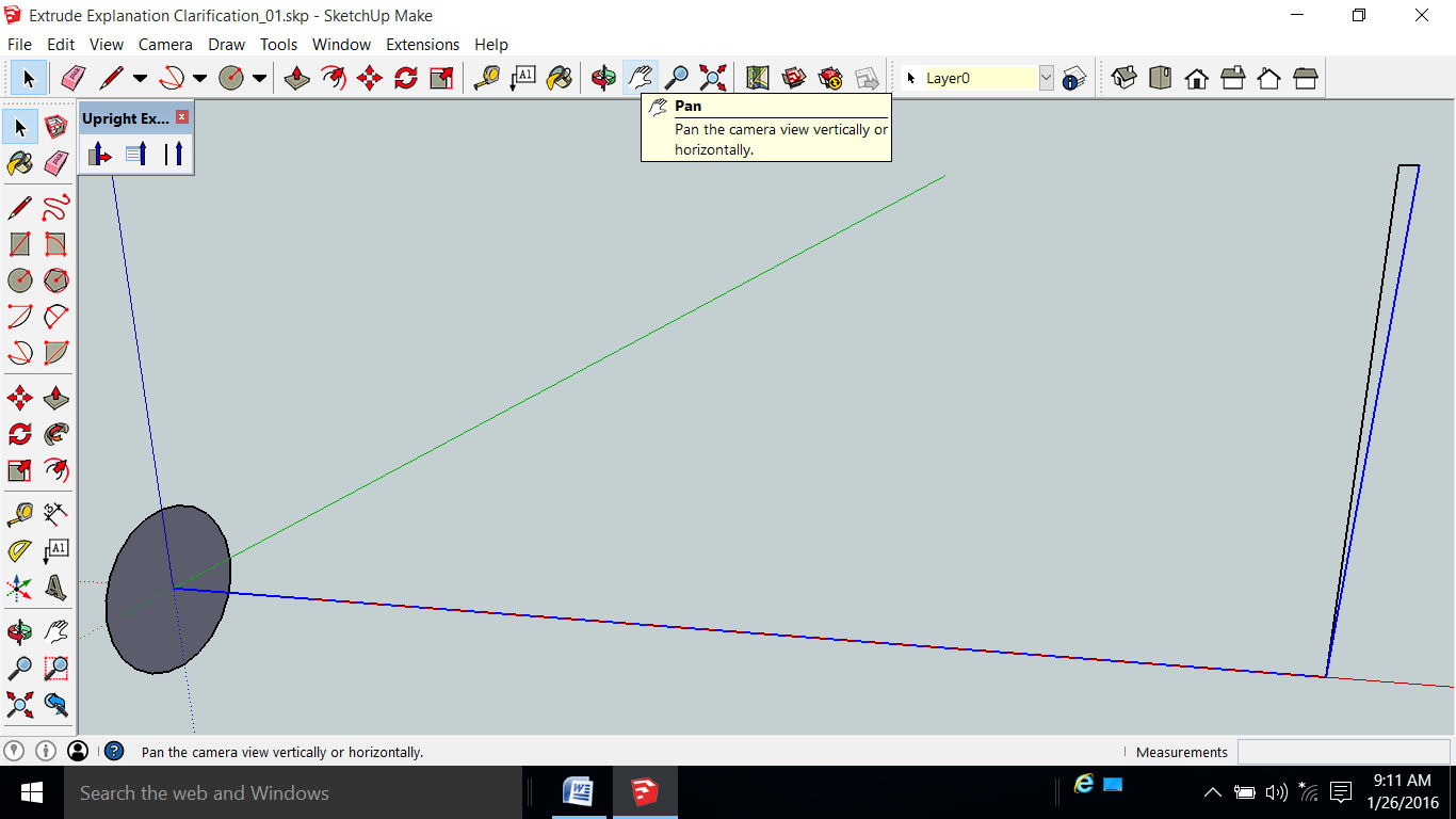
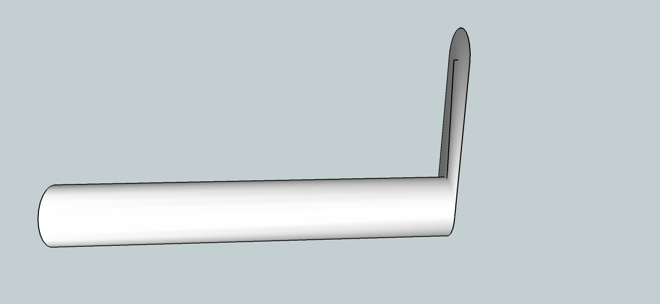
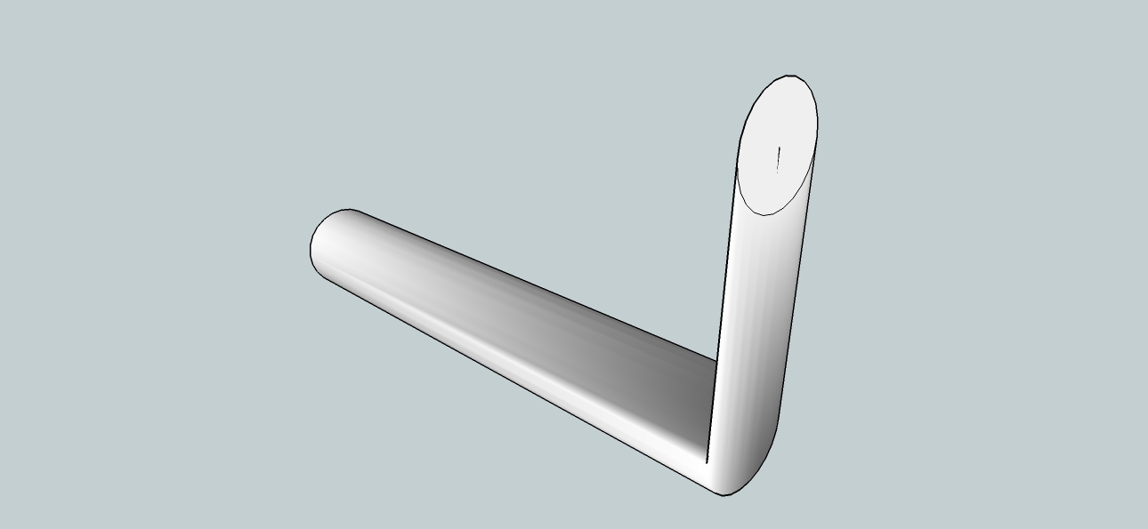
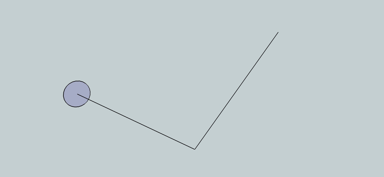
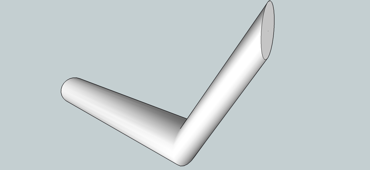
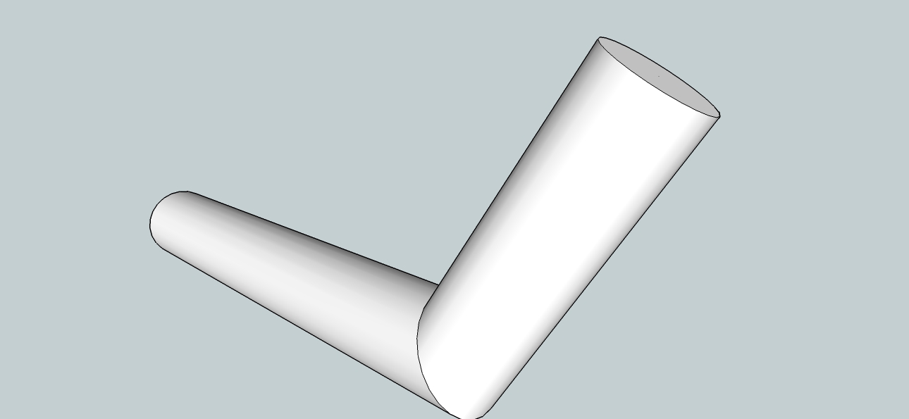
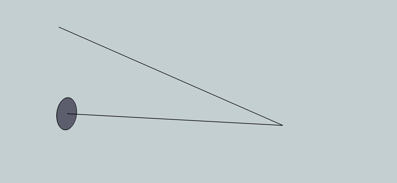
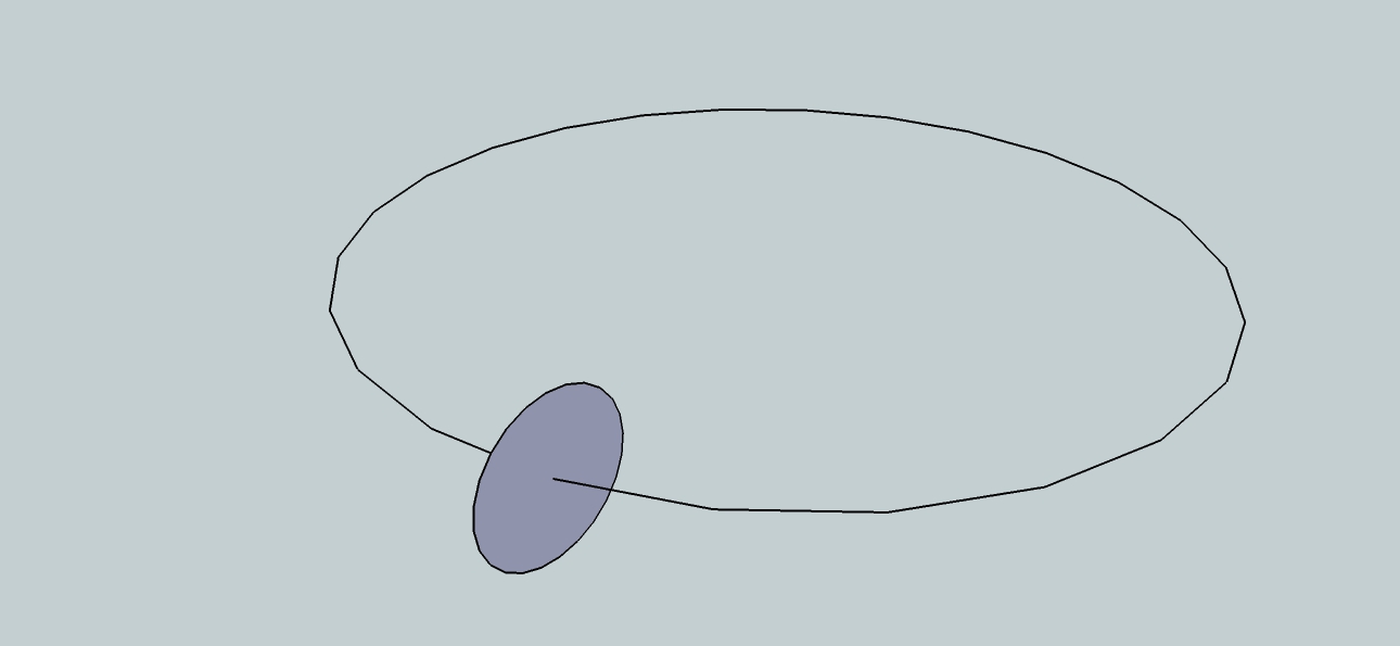
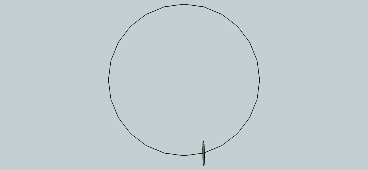
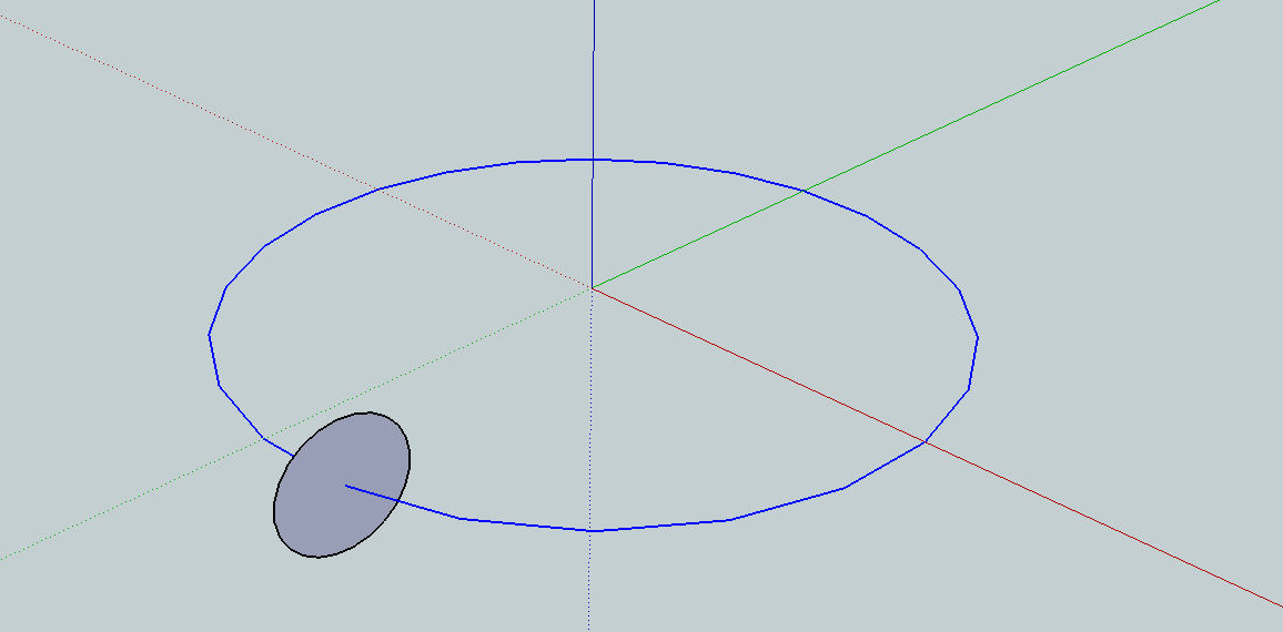
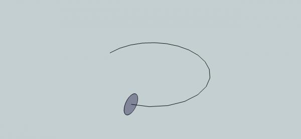
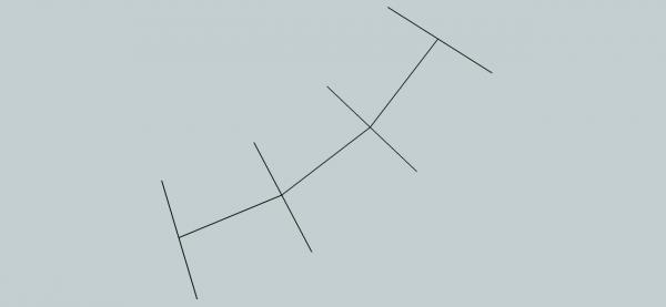
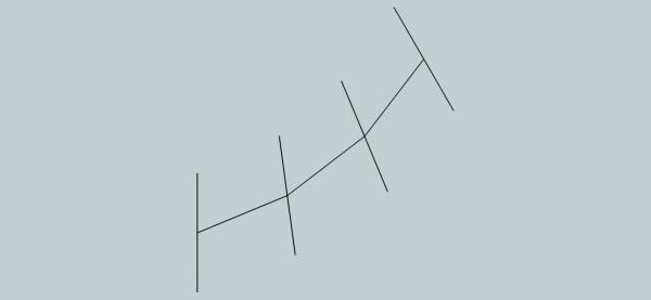
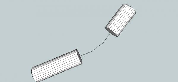
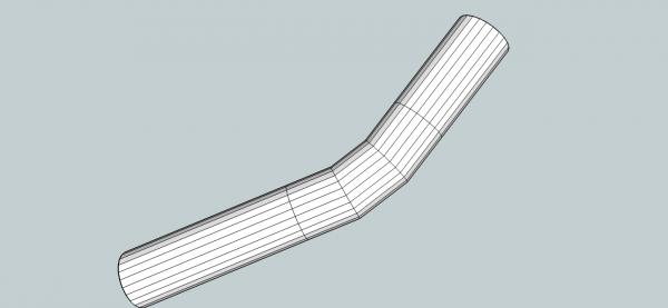
Part 11A Part 12 will discuss the winch drawing, promise. I’m already writing it up. I think a more detailed explanation of how the Follow Me and Upright Extruder work is needed. I will use some example extrusions to show the differences. First the Up Right extruder cannot do an extrusions for a path with a sharp angle in it. The first examples are the results of trying to extrude a face, with a 90 degree bend in it. For the Follow Me And for the Upright Extruder Because the Upright Extruder was trying to keep the faces parallel to the original, it was unable to turn the 90 degree corner. If I angle the vertical line just a little, the Upright Extruder, can create an extrusion, but it is distorted. Angling the line a bit more results in a fuller vertical shape, but still oval in cross section. While the Follow Me gives us a circular vertical cross section. The follow Me can also do the extrusion of an acute angle. Now we’ll take a look at what happens when you extrude along a circular path. The surface is not in line with the path, it was drawn along the green (Z) axis, to demonstrate the differences. The picture below shows the extrusion path, in blue.