thibaultron
-
Posts
2,951 -
Joined
-
Last visited
Content Type
Profiles
Forums
Gallery
Events
Everything posted by thibaultron
-

Fokker Dr.I by Torbogdan - FINISHED - Model Airways
thibaultron replied to Torbogdan's topic in Non-ship/categorised builds
Construction of a modern Newport replica. http://www.aviationmaintenance.edu/blog/great-war-aircraft-project/aim-chesapeake-ww1-nieuport-24-building-continues/ -
Fokker Dr.I by Torbogdan - FINISHED - Model Airways
thibaultron replied to Torbogdan's topic in Non-ship/categorised builds
Reklein; Thanks for the pictures. I looked at the MA pictures, and they left the insides of the ribs with the char, as did all the other buit pictures I could find. -
Fokker Dr.I by Torbogdan - FINISHED - Model Airways
thibaultron replied to Torbogdan's topic in Non-ship/categorised builds
Here are a couple links to other builds, one the DR1 and the others of other Model Airways kits. http://www.lazuli.com/n_projects/n_dons_projects/n_fokker/index.html# http://www.modelshipbuilder.com/e107_plugins/forum/forum_viewtopic.php?16206 http://www.ipmsgreatplains.org/camel.aspx I liked the way the DR1 biuld added some color to the model, but not too much. I have the Sopwith Camel, DR1, Newport, and Wright Flyer kits.- 250 replies
-
- 13
-

-
Fokker Dr.I by Torbogdan - FINISHED - Model Airways
thibaultron replied to Torbogdan's topic in Non-ship/categorised builds
Reklein: Did you remove the char inside the wing ribs? If so, how. -
Fokker Dr.I by Torbogdan - FINISHED - Model Airways
thibaultron replied to Torbogdan's topic in Non-ship/categorised builds
I too have this kit, and will be following the build. Model Expo is very good at helping modelers, email or call them for an answer to the spar construction. -
If you have a coping/graphics place near you, see if you can get their discarded cardboard roll centers. They are great for storing rolled plans. I roll the plans print side out, they lay flatter when you go to use them.
-
You can also use GIMP, a free graphics editing program.
-
You can change the color of the render, by either: 1. Actually change the color of the lines in an object, such as the cannon. 2. Change the material the object is "made" from, such as changing the cannon to Brass, and the carriage to Wood. Both are simple and quick.
-
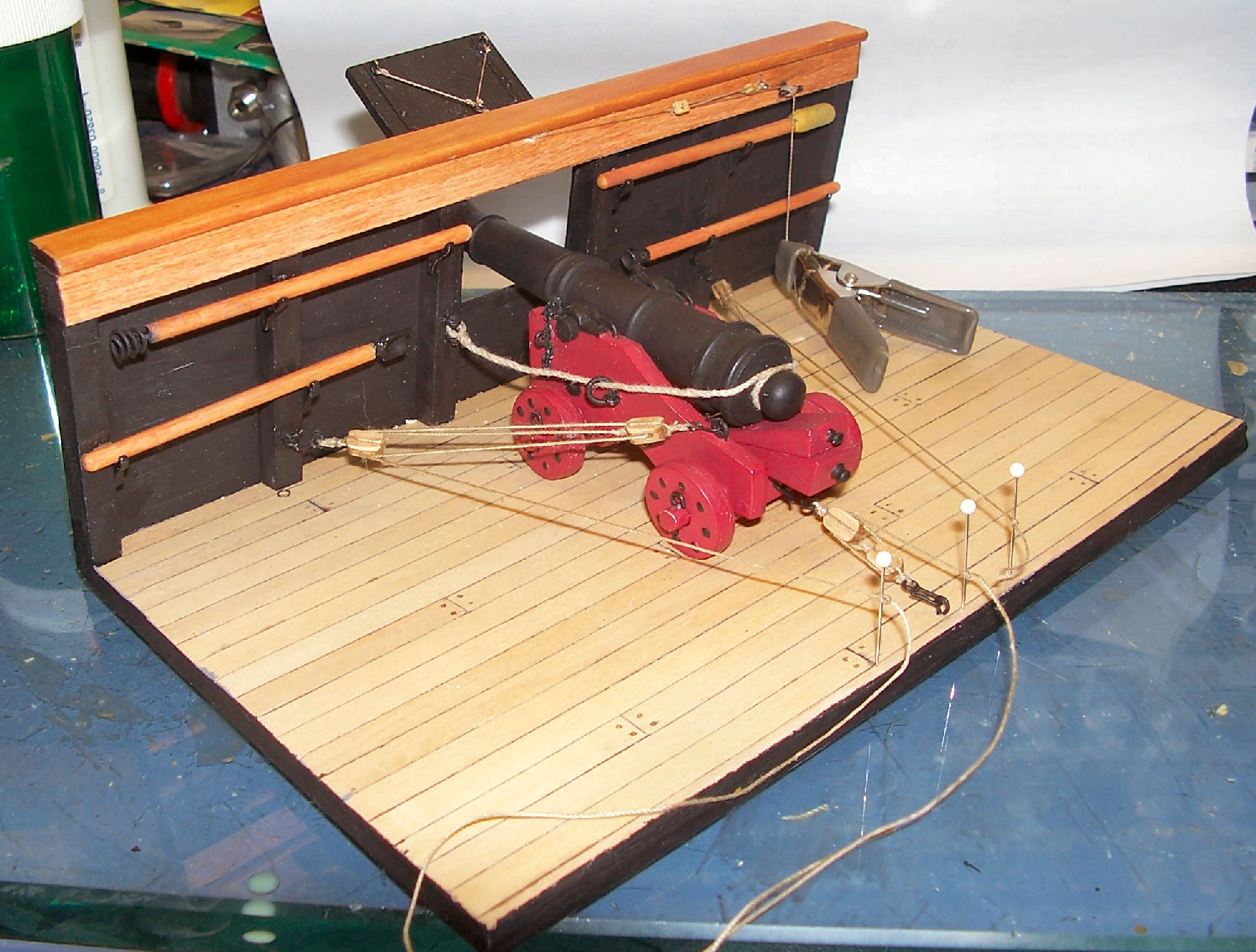
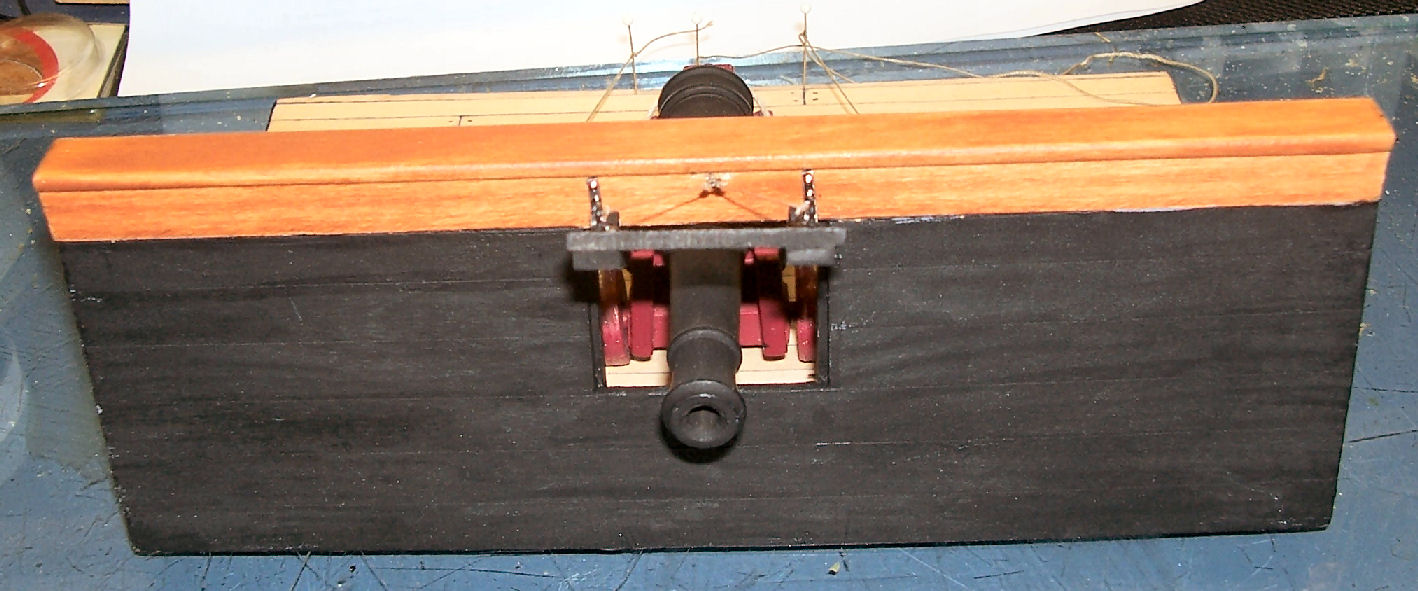
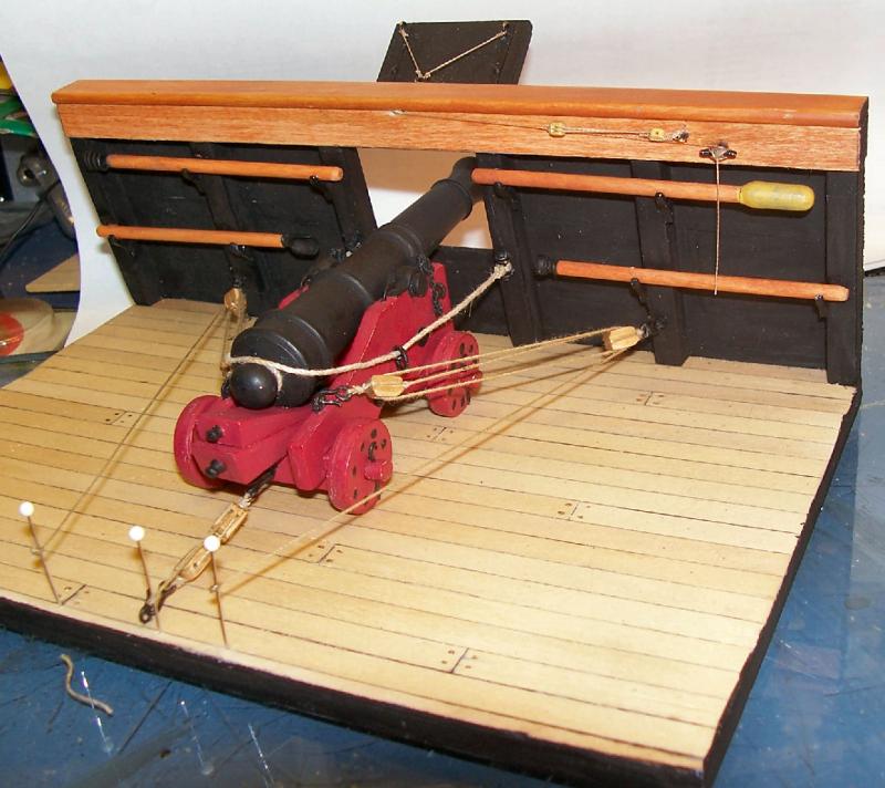
I just finished on of Model Expo's Naval Cannon kits. Nice large size, and uses several of the technquies you need for a regular ship kit. I added hooks to the gun tackle ends, and used rope stropped, rather than metal stropped, blocks. The later were what was shown on all the drawings I could find. Model Expo promptly replaced some of the deck strips I messed up.
-
Keep calling till you get them.
-
How about ribbited? That's when you get a frog caught in your planking. :-)
-
I had a thread "Going From A 2D Drawing To A 3D Printed Part Tutorial" that focuses on SketchUp, but does have much info on designing parts for 3D printing. It might help you.
-
I remember a car restoration show I saw several years ago. They started with a late 60s muscle car, to be restored. As they stripped the body, they found more and more hidden rust. Finally they replaced all the sheet metal, except the piece between the rear window and the trunk!! The modern version of a "Great Rebuild"!
- 749 replies
-
- 3
-
-
- albertic
- ocean liner
- (and 2 more)
-
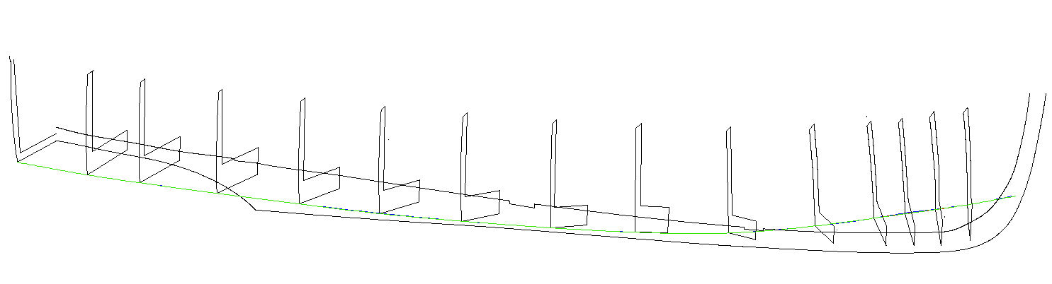
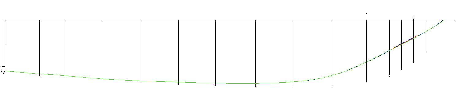
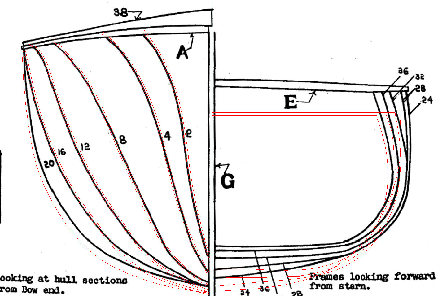
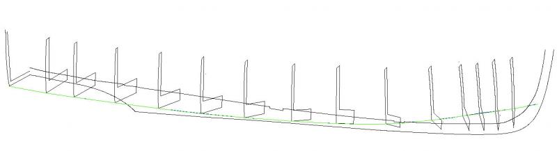
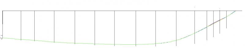
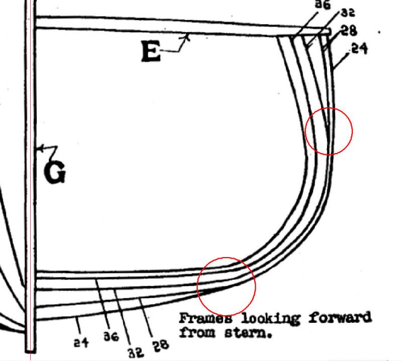
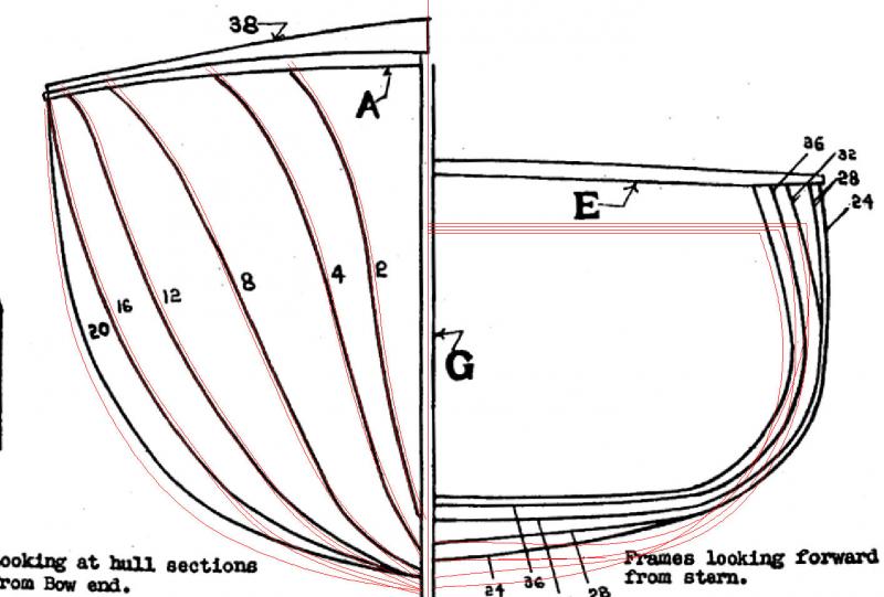
If you can used the 3D, lay out the frames in position, and draw (in DesignCAD) a curved line along them at a fixed height. If the frames are correct, the line should be smooth in all directions, if a frame is out of line, draw the curve skipping it, and see where the correct point should be. Below is, hopefully, an example. Why do this rather than a physical model? I can scale this to any one desired, and after I do I can used the parallel function to put in the lines taking account of the hull sheeting thickness I will be using. Picture 1: The 3D frames with a waterline drawn. Note that the lines run along each other, except at the bow area frames. Picture 2: A top side view: Note where the lines diverge. Picture 3: A close up of the areas. The blue and red lines where the first and second attempt at laying the lines. Note how they bulge at the second and third frames, from the right. The green line is after I redrew those frames, with the corrected distance from the keel at that waterline. Here doing a model would be close enough for you to get an idea, but look at the next shot. Picture 4; The before frame drawing of the hull lines. Note where frame 28 goes into the curve on one line and comes out on another line, and they don’t meet in the middle! Picture 5: The before and after hull lines. The fore frames line up fairly well, but look at the aft frames! The original drawing was not even close!! The waterlines were run as in the previous pictures, from the transom to the stem, with a lot of iterations in between.

-
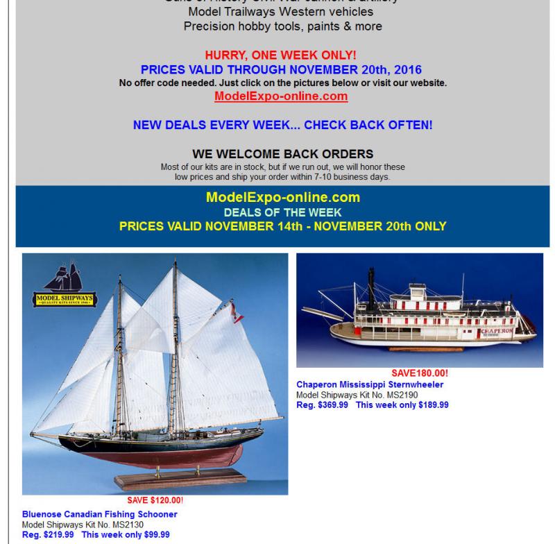
Until tommorow Model Expo has the Blue Nose for $99.99. It is on back order at the moment. The model is of the original Blue Nose, not the reproduction II. I've attached a screen shot of the ad they sent me. They are presently listing it a $140, not the $220 they show in the add.
-
Does your CAD have a 3D capability?
-
Model Expo also has praticums by Chuck for both the Phantom and Sultana kits. They are available as downloads online in the Documents tab of the kit page.
-
Instead of masking the bands, you could paint the whole funnel "Funnel Color", then mask this and paint the bands. That might be simpiler than trying to mask the curved band surfaces.
- 749 replies
-
- 3
-
-
- albertic
- ocean liner
- (and 2 more)
-
I think you have the right approach.
-
Are the original plans paper or a file? Which ship/boat? I can probably help with more info. Can you post a jpg of the plan?
-
Paint stripper may work, also I have heard of burning it off. You'd have to be careful not to burn up that small a wire, though.
-
Finding the center of a dowel
thibaultron replied to KenW's topic in Modeling tools and Workshop Equipment
Machinists use several different tools for this. Look up squares in any metal working catalogs. One type is a Center Square. Another is a Combination Square. The usefulness of each type would depend on the dowel size. The Combination Square would work for all sizes, but can be a little awkward for really small dowels. Below is a picture of a Center Square.
-
I know, but there was not enough deck space (length from hull to back of deck piece), for the gun to run all the way back. Maybe if I had not added the hooks, there might have been, but not with them on the tackle. The shorter breaching rope was a compromise, to make it look like the gun would not run over the tackle at the rear of the carriage. I preferred this compromise to not having the more noticeable tackle hooks present.
-
Allanyed; Thanks for the information!! I finished the model yesterday, and choose to display it with the lines running off the diorama under tension, as if the men were pulling it back out for firing. I will keep this information for my next kit. Thanks, again.


-
Another question. How were the free ends of the lines for the gun tackle secured. All the diagrams and plans I've been able to find, just show them going off the picture. The model shows them loose with the end Flemished, but that would leave the gun rolling around freely, and I'm sure the Flemished coils would be a tripping hazard.