thibaultron
-
Posts
2,951 -
Joined
-
Last visited
Content Type
Profiles
Forums
Gallery
Events
Everything posted by thibaultron
-
 According to research on the internet. First set the parts out in the sun for a day. The parts are UV cured, and Shapeways does not always cure them long enough. Wash in hot soapy water, then rinse. Prime with the paint of your choice. Enamels or acrylic, I'm not sure if lacquer would damage it.
- 1 reply
-
- 2
-

-
I don't know if the book is correct, but the AOTS "USS Essex by Portia Takakjian, shows gun port with lids with rigging that would hold them at a similar angle to that used in the MS cannon diorama. These ports are below the weather deck, but with not much more height between the top of the port lid and the point that the lanyard enters the hull. As I already have the lid mounted, I'll just go with that setup, but use thread instead of the chain. It may not be 100% historically accurate, but it looks OK. Unlike the MS kit, though, I made hooks for the ends of the gun tackle to carriage rigging. The MS kit has the blocks served directly to the carriage eyebolts, but all the diagrams I found show the hooks. They also show the blocks as iron stroped, but the diagrams all show rope stroped, so I'll use thread for this too. Luckily there were just enough spare eyebolts and cut offs from the tails to make the hooks. Bough three different jeweler's beading and ring makers pliers for this and future jobs.
-
The lid is already attached. Most observers would expect one to be there anyway, even if I know that it should not be there. I'll use rope instead of the chain. Forty years ago my hands shuck a lot less than they do now, and thread is easier than working with really small chain, besides I have another model whick that chain would be perfect for.
-
P.S. I'm trying to model an American flavor look.
-
I'm building a MS Smoothbore cannon model, and I have a question about the "rigging" used to raise the gun port cover/lid. The kit supplies chain for the external and through the bulworks portion of the rigging. This goes to the first block, and then line is used for the rest of the assembly. I looked at several AOT ship books and they show Lanyards (I assume rope) used for this. I'd think chains would wear away the paint and chew into the wood. So, finally, were chains ever used, or were rope leads more common?
-
Wood masts for a plastic model... Tips?
thibaultron replied to SomethingIsFishy's topic in Plastic model kits
I have found wood dowels almost unuseable. For my Pyro skipjack build, I went through my entire collection of kits (good and bad name manuf.), and found maybe 3 straight dowels in the lot! I'm planning to make masts from square stock. I already made the bowsprit. Not your typical job, as the bowsprit on a skipjack curve downward toward the fore end. I made the sprit from a larger dowel that I squared (rectangulared?) up then cut in the curve, and shaped it. This is actually how the real bowsprits were made, the curve was cut into the spar, it was not bent into shape. I used the dowel as it was all I had at the time. For the mast, I have both basswood, and boxwood. I'll practice on the basswood, then make the final one out of boxwood. Unless the basswood mast looks really good, then I'll save the boxwood for another project. -
Tool Maker's Surface Gauge
thibaultron replied to jbelwood's topic in Modeling tools and Workshop Equipment
Another thing, if you are going to leave the plate glass in place permanently. If the surface under it is uneven, you can build a temperary frame around it, and pour in liquid RTV. It will flow under the glass, and fill the voids. Once it cures, remove the frame and trim the RTV. Now the glass is evenly supported under neath. -
Tool Maker's Surface Gauge
thibaultron replied to jbelwood's topic in Modeling tools and Workshop Equipment
Another good "Flat" surface, is a thick piece of plate glass. -
I'm building the Model Shipways Smoothbore Canon diorama, and have an esthetics question about the bulwark clamp and railing finish. The completed model photo on the box shows the bulwark clamp and railing stained, which I have done. The question is should I use matte or gloss varnish on these pieces? I've used matte on the deck, but gloss on the two stained pieces would make them stand out better, now that I've stained them. However would a matte finish be more realistic? The bulwark will be flat black. Should the bottom of the clamp also be painted black, or would it also have been "bright work" finish?
- 1 reply
-
- 1
-
-
You could call a museum curator, they should be able to give you some advise, or leads at least.
-
I looked at the plans, they attach on the deckhouse right by the railing to the steps. I have a copy of the plans I bought for my Lindberg plastic Harriot Lane.
-
looking at ships, what's the best boat for a newby?
thibaultron replied to shutter's topic in Wood ship model kits
In addition to the kits mentioned, I think there is another concideration for you to make. If you are interested in building a model, you are probably also interested in ship/boat history. A less involved kit is what you need, but one that fits your interests should also be a factor. See if there is a kit that fits that interest, or read the history of the ship/boat your are looking at, and see if it grabs your interest. For instance, I lived in Maryland for many years, and love the Chesapeake Bay, so many of my kits, and several plans are for boats from this area. Skipjacks, crabbing boats, and other fishing boat subjects are what I'm more interested in. This is not to say that I don't have kits or plans for others, I do, but I especially look for those kits when I see them available. You don't have to start with a wood kit either, there may be a plastic kit that you might want to build, to get started. I have both, and a well researched plastic kit can be as challenging. I'm slowly building a plastic skipjack model, with heavy mods to bring it to the correct configuration. I'm even doing 3D printing for some of the needed detailing. I also learned during my research that some features of the kit I thought were incorrect, were actually right, even though logic pointed otherwise. -
On the page for Model Shipways Phantom, in documentation section, is a praticum for the Phantom. The kit is also a solid hull model. It may help you with yours, and is much more detailed than MS's regular booklet. I recently bought the plans for the HL, to use in building my plastic PYRO/Lindberg version of her.
-
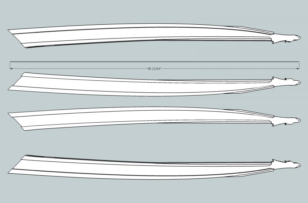
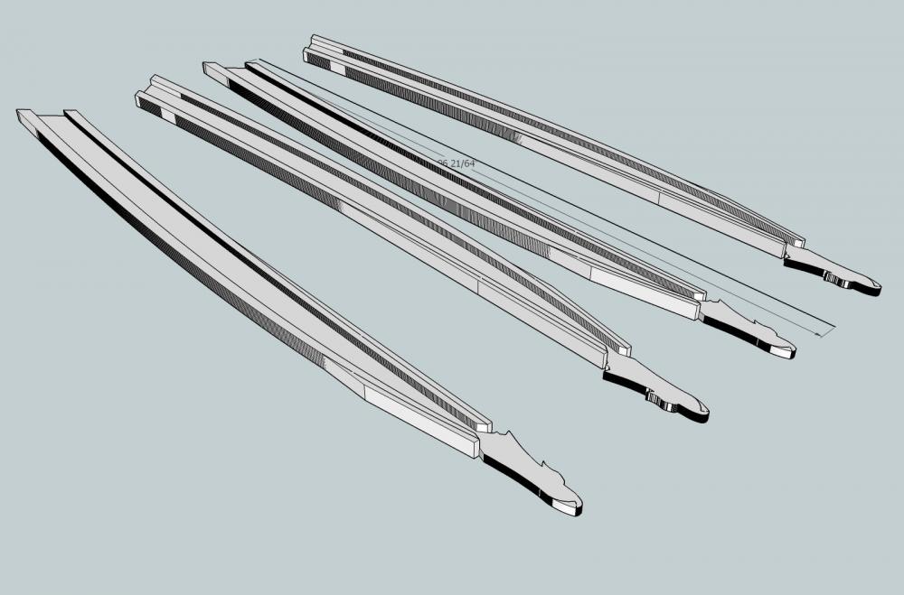
Haven't abandoned this build, been working on shop. The major renovation is done, and I can start moving stuff back onto shelves. Then modeling can resume. I sent out the rigging details for printing, and they came last week. 2 of the 4 bowsprit braces were warped, but the other 2 look useable. I broke my magnifying lamp light bulb, so I can't take pictures right now, nor can I see how well they turned out.
-
Plastic or wood kit?
-
Source for belts for Dentist Drill
thibaultron replied to thibaultron's topic in Modeling tools and Workshop Equipment
Neptune; Thanks for the link! I've book marked the catagory, and will be getting some in the future! -
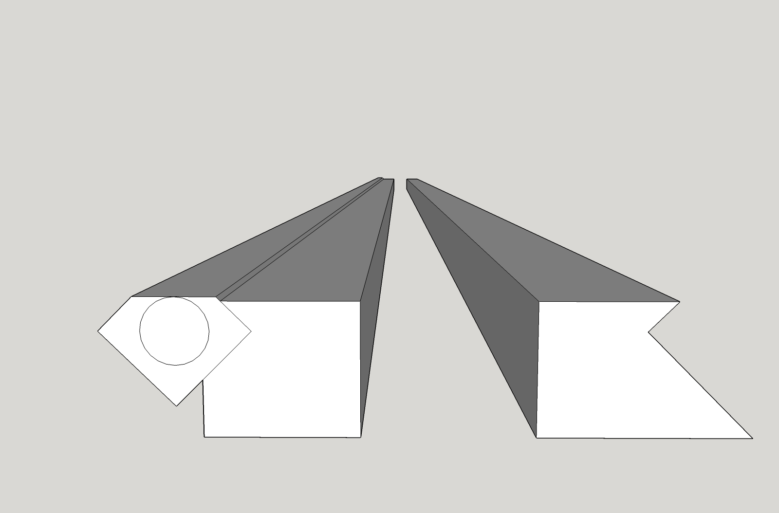
I have an old style table top Dentist Drill, that I want to use for carving, but there are no belts with it. Does anyone know where I can buy some belts for it?
-
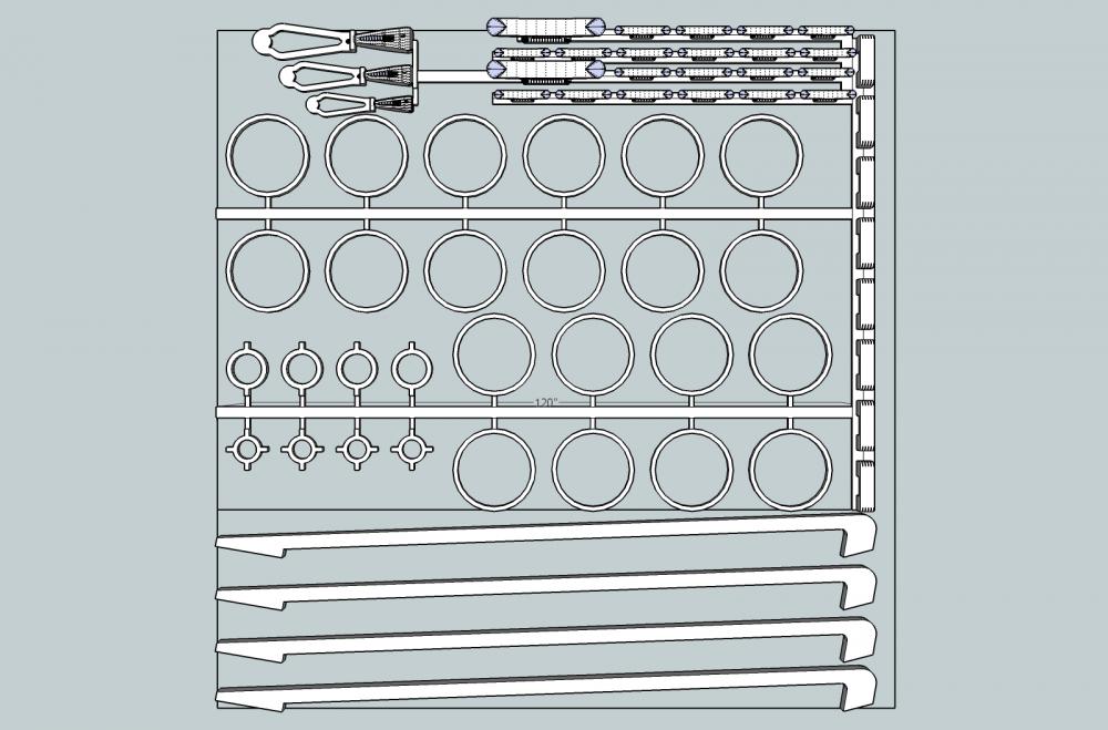
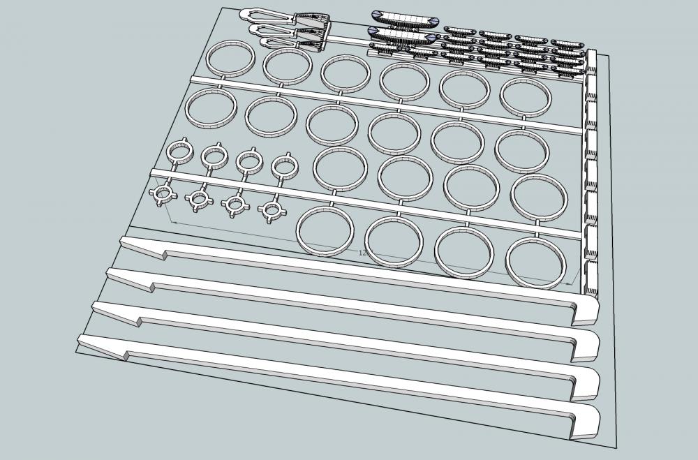
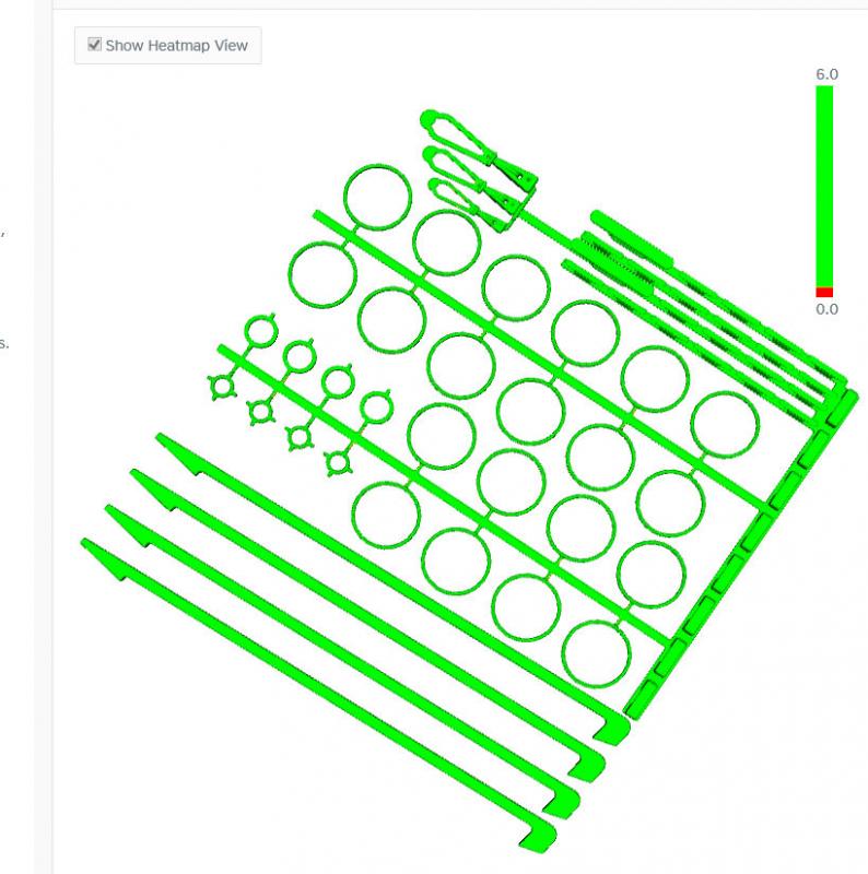
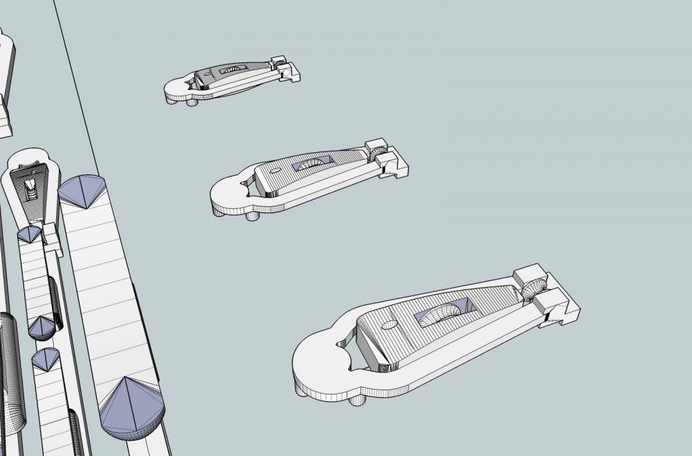
Part 30 I finally have a good 3D file for printing the rigging details. I gave up on having the complete sheave in the horse block, and redesigned it with only the lower hole, and the top part grooved like commercial model blocks Here are pictures of the final rigging detail file. And here is the Shapeways screen shot, all green.
-
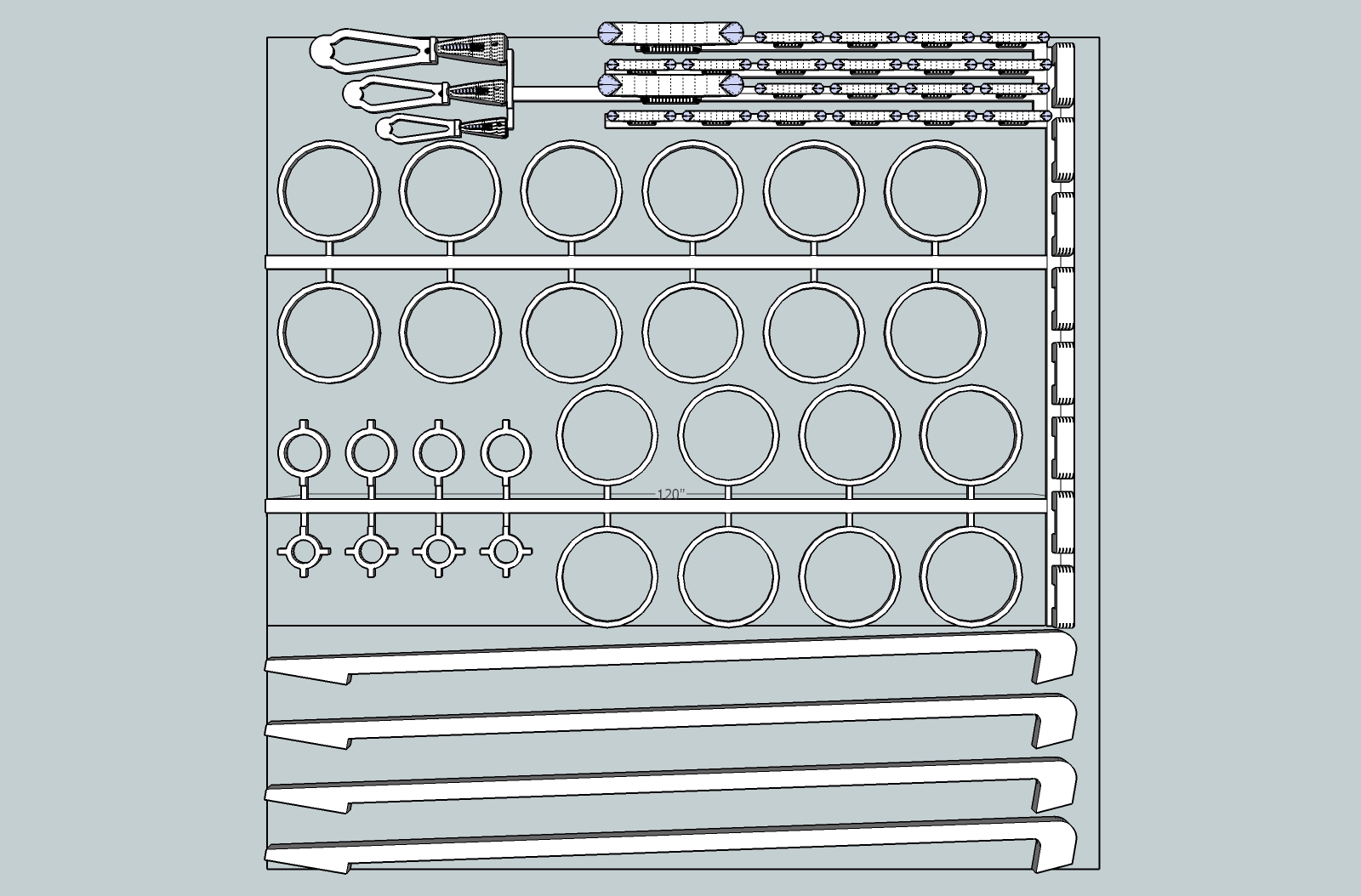
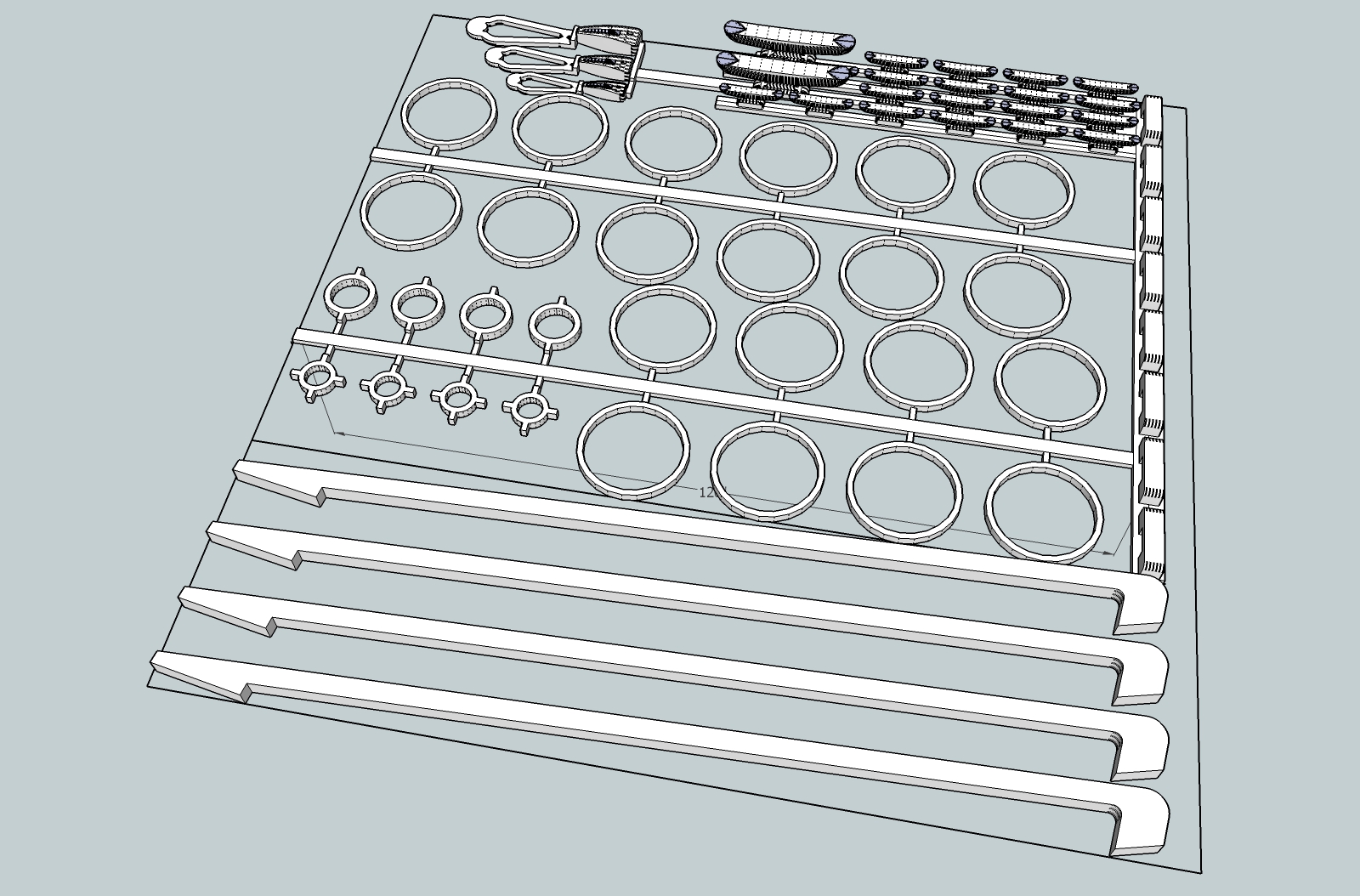
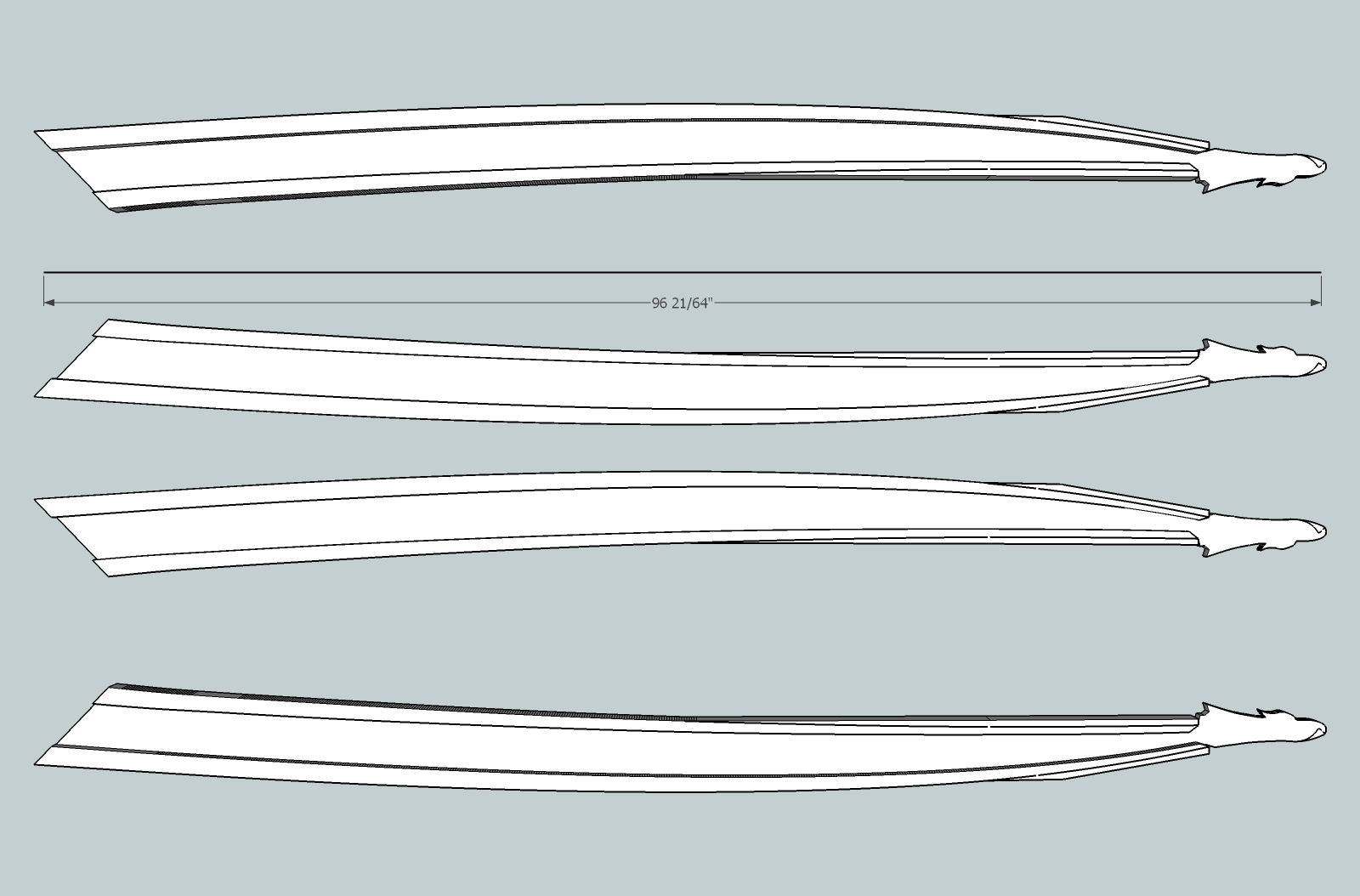
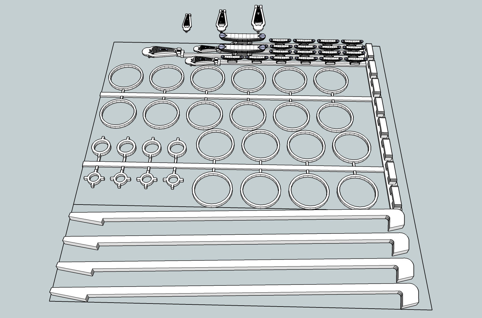
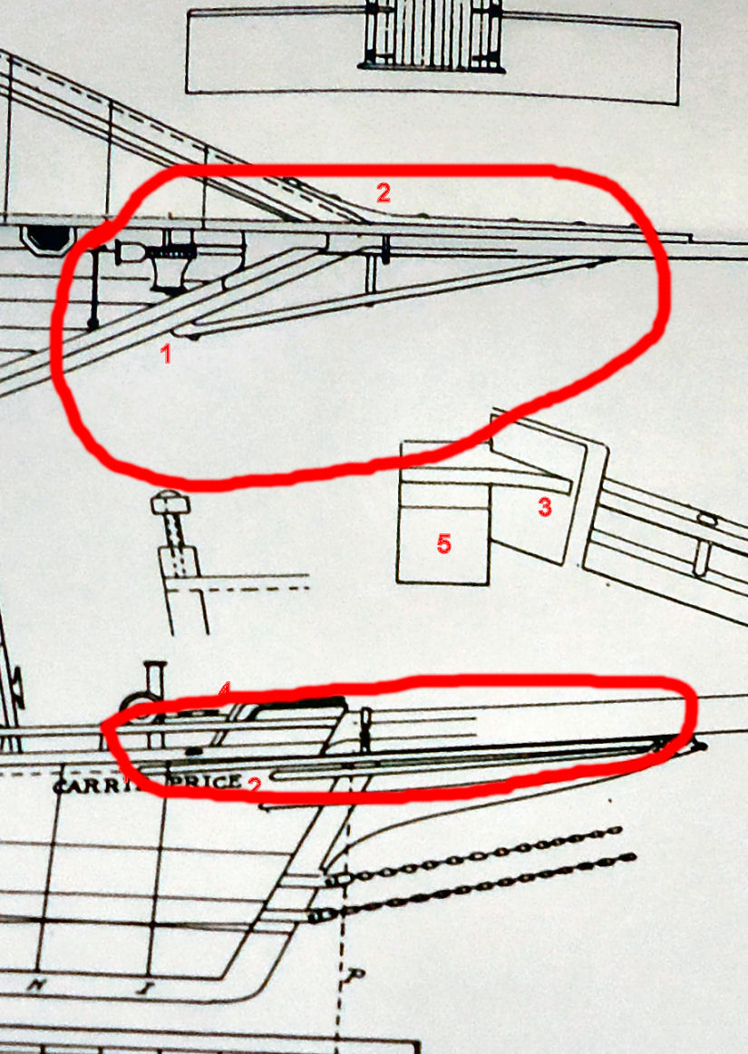
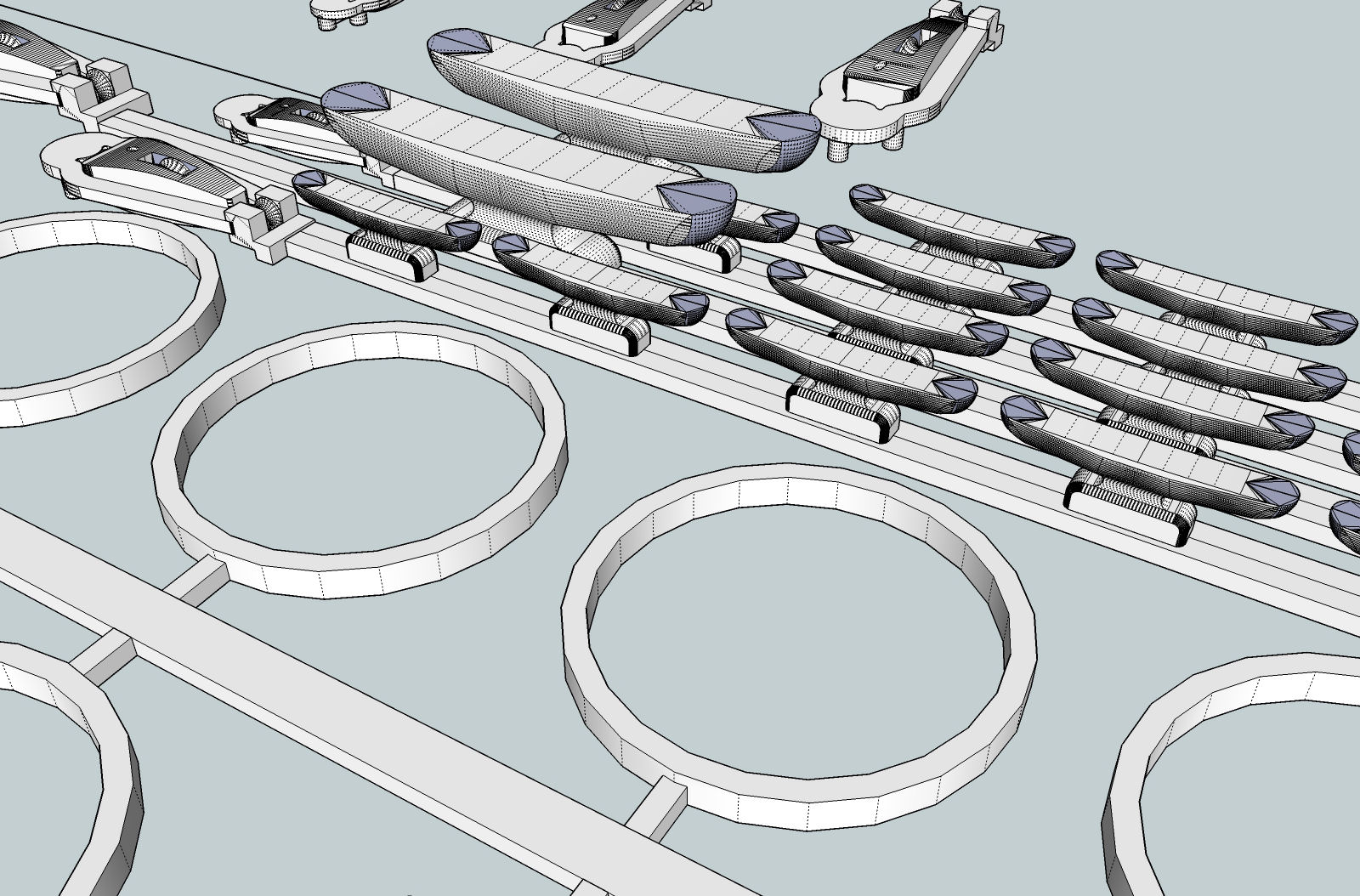
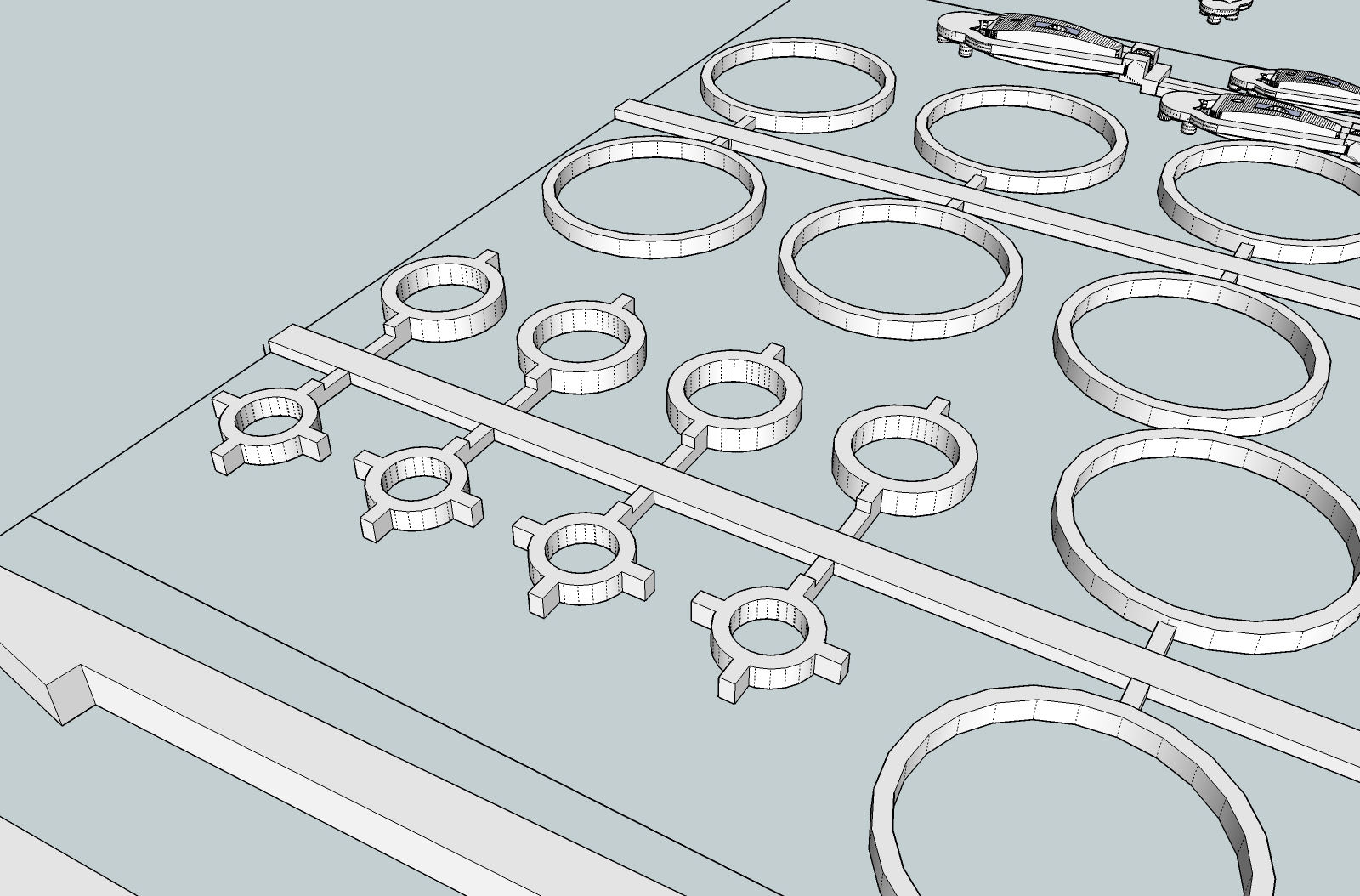
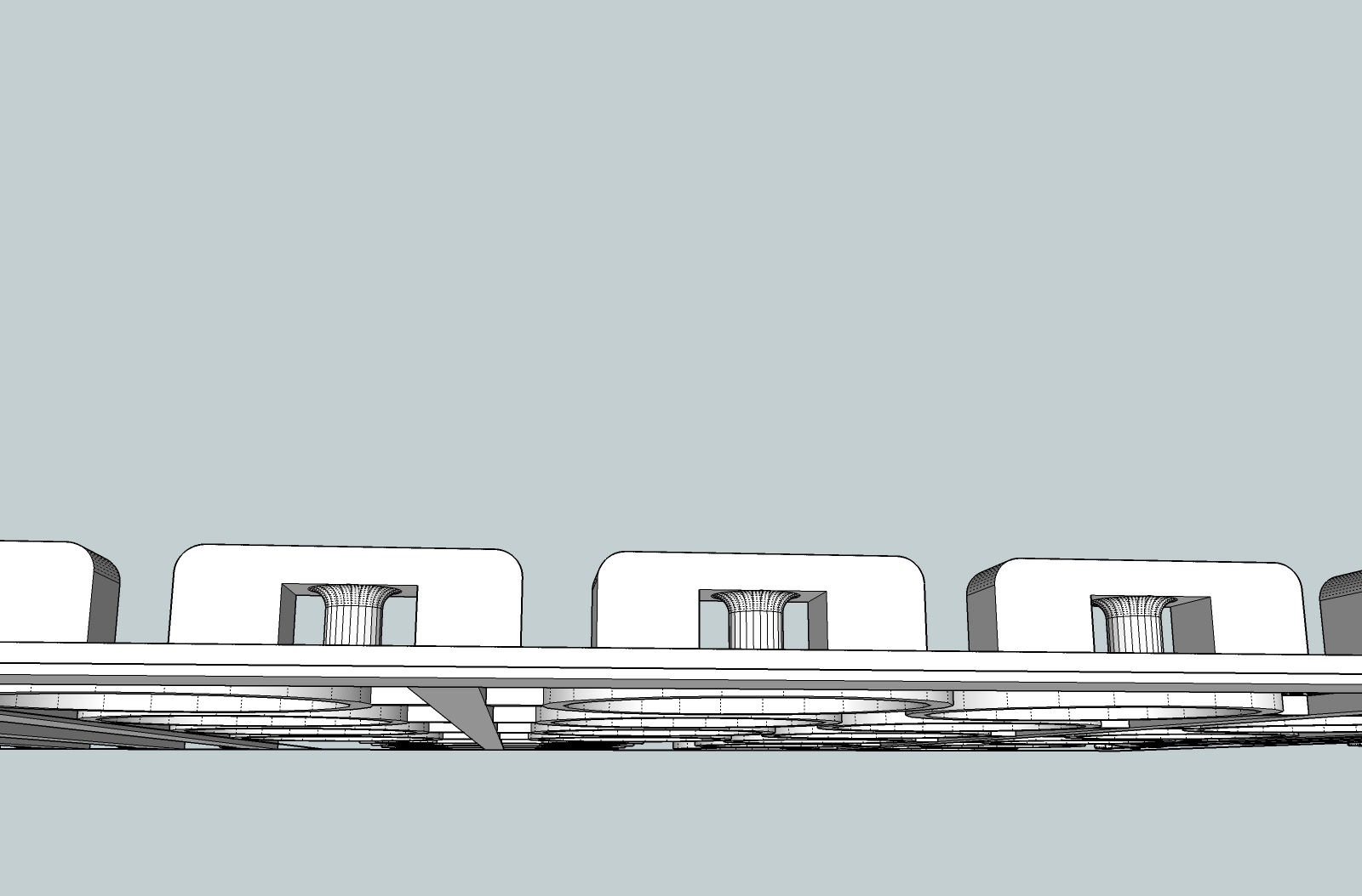
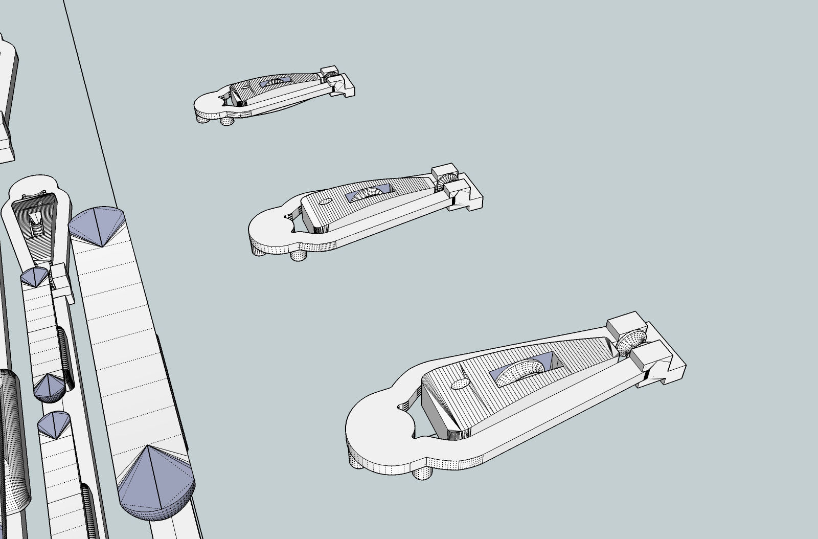
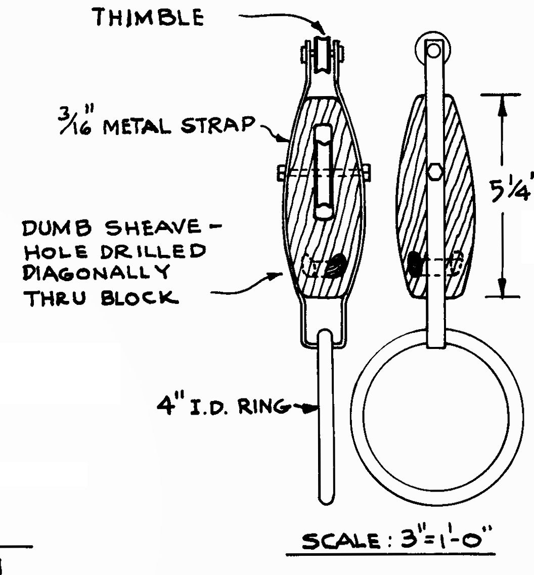
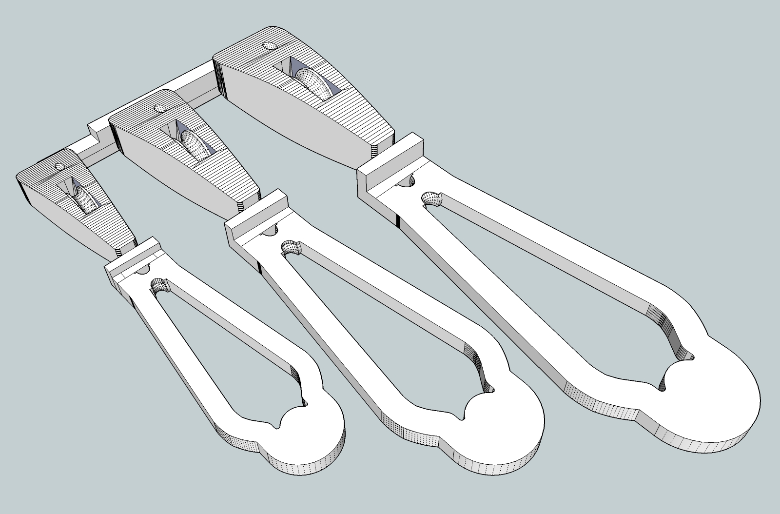
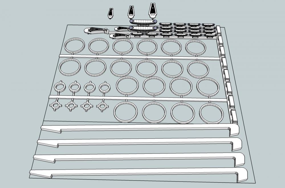
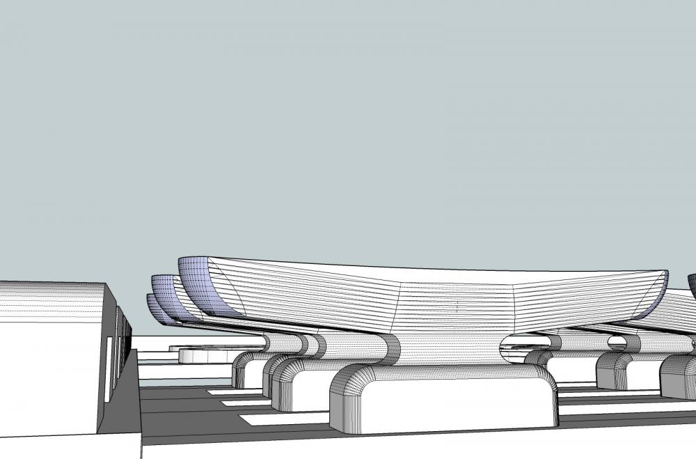
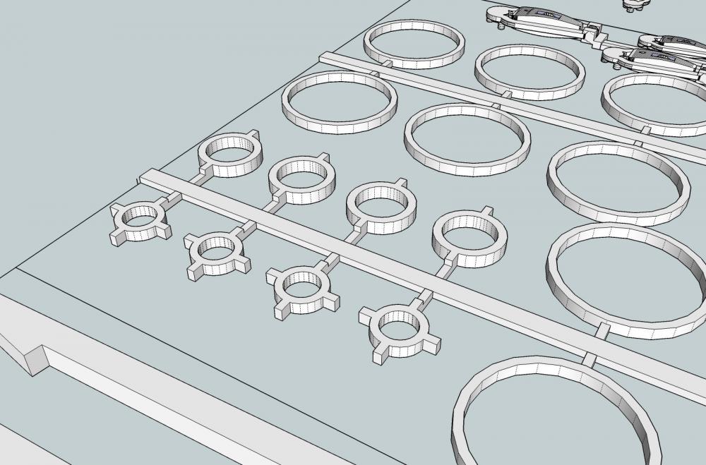
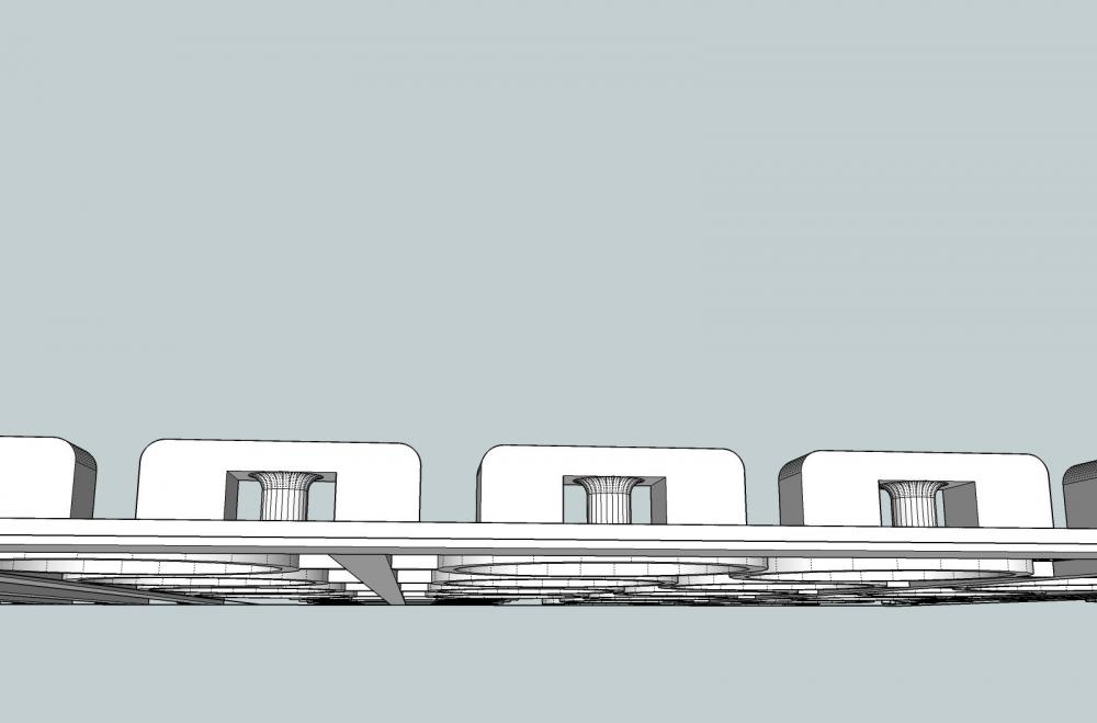
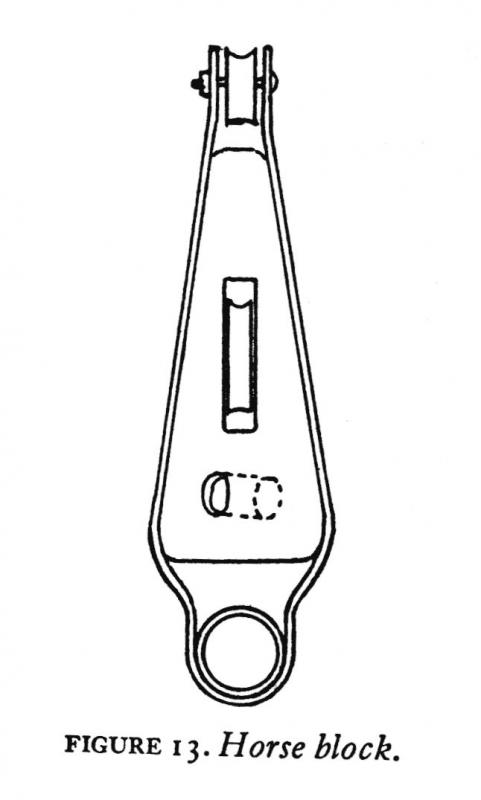
Part 29 Just in case you thought that I have abandoned this build, here is some progress. I have not done anything physical to the model, but I have made some 3D drawings of some of the details. Why the lack of progress? A friend gave me some thick foam board insulation sheets, that I will be using as the base for my model railroad, so I have been concentrating on getting the shop reorganized, the layout leg/book shelves/computer desk/workbench assembly put up, lately. I just got the workbench cleared, so I will be doing more work on the ship soon. Well the news from Shapeways on the Dredge Frames was bad. Because the frame is made of round bar shapes, the tolerances on minimum size are larger than for square shapes. The 1/64th scale frames are just too thin to print, period. The 1/32nd scale ones can be printed by increasing the size, they will be a little over scale, but not too bad. Back to square one on these. The new parts I drew were the trailboards, and some rigging fittings. I submitted the trailboards to Shapeways, and they were good, I should have them next week. I tried to create a 3D eagle head, but it was just too small, so I’m going with just the outline. It’s so small that I don’t think the detail would show anyway. I also had to make the molding boards a bit thicker at the end where the eagle head is. I’ll sand them when I go to install them. I have not submitted the rigging details yet, I’m still having trouble with the Horse Block. This is a special block for the jib traveler. More later. Here is a picture of the rigging detail drawing. All the parts except the Horse Block (top, and upper left) pass the initial inspection. At the bottom are braces that go between the hull and the side of the stem, just below the bowsprit (circled in red below). The model had these cast on, but they were warped, and one was broken, so I’m going to use these. I could have fabricated them, but I wanted to print the fittings anyway, so I included them. At the top right are cleats, 10” and 21”. The larger cleat is used for tying off the center board lift line. The larger rings are mast hoops. The fittings just above the braces, on the left, are the bowsprit cap fitting (below), and the mast head fitting (above). Here is a close-up. Along the right are cheek blocks, for the lazy jack lines. They attach to the sides of the boom. The horse blocks are shown below. I am having a hard time getting them right. I’ll have one configuration pass, then when I add the two larger sizes, all fail. The center sheave also has a distressing habit of disappearing when Shapeways checks it. I need to work on these more. I have three different sizes, so that I can pick the one that I can work with better. Ideally the smallest one (which is scale), should be used, but I may have to use one of the larger ones, just so I can handle it. One of the larger ones may also look better on the model (better detail, or appearance), even if a little large. The hole below the center sheave, is drilled diagonally through the block. I used the drawing in the book as a basis, and used the general size on the Bennett drawing to get the dimensions. The Bennett block is shorter, so I matched distance from the bottom of the block to the axle of the center sheave on the Bennett to scale the Carrie Price one. The hole in the strap at the bottom created walls too thin to print, so I will drill it out later. Carrie Price block Bennett block The present configuration of the part for printing is below. I have to print the strap as a separate part, otherwise it is a projecting wall, and must be twice as thick as the minimum .3mm tolerance. I will be using the cleats, cheek blocks and the horse block, at a minimum. I’ll decide about the others when I get the actual parts. I have included several extras of each part, just in case. For those of you who are following my 2D to 3D tutorial, I will soon be adding sections on drawing the horse block.


-
Mills...Spindle Speed
thibaultron replied to Bill Hime's topic in Modeling tools and Workshop Equipment
In respect to the back lash you mentioned. All mills that we are likely to encounter, have back lash. You need to determine what this is for the feed screws on your mill, and remember to take this into account when using it.\ Alternatly you could try to fit it with a digital readout, very expensive, but very accurate. -
Sultana figurehead discussion
thibaultron replied to CharlieZardoz's topic in Nautical/Naval History
Thanks for the Scupltris link! I'm going to check out the program. Looks interesting! -
Sultana figurehead discussion
thibaultron replied to CharlieZardoz's topic in Nautical/Naval History
For those of us who are not yet at the skill level of carving a full figure, I would suggest looking at available scale figures as a starting point. You could at a minimum use the head and torso, using some type of material to build up the clothing. For the Sultana, 1/64th scale figures are available from the model railroad suppliers (a limited availability in this scale). If you wanted a smaller figure head 1/72nd figures are available on a more limited basis in the model airplane and military armor suppliers (you may have to buy a plane or vehicle kit just for the figures. For a larger than life figurehead, 1/48th scale model railroad figures are also available. -
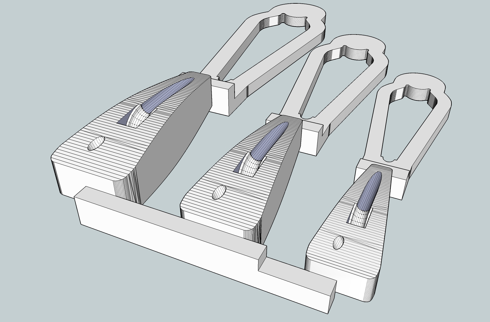
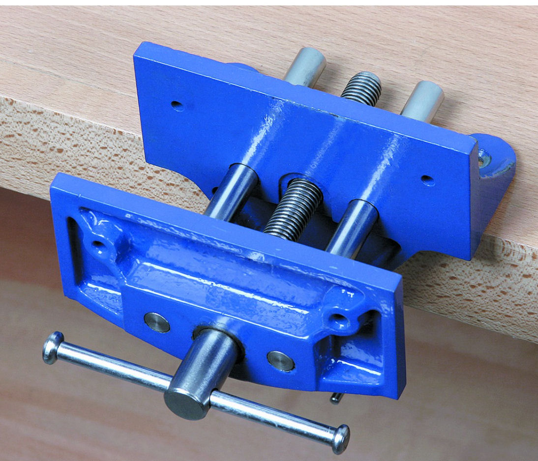
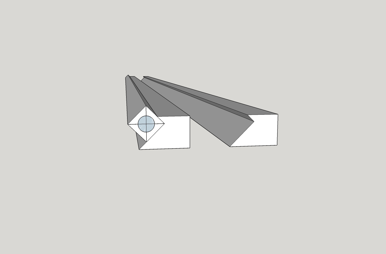
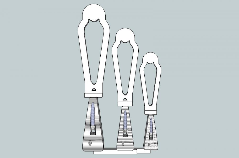
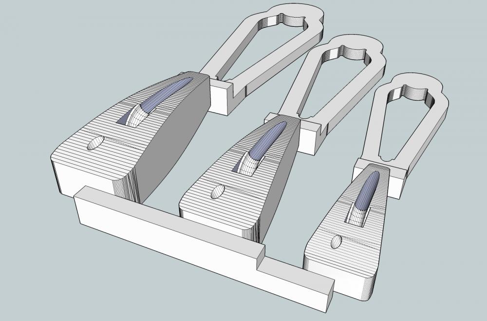
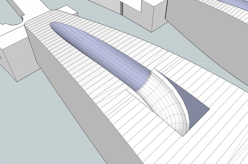
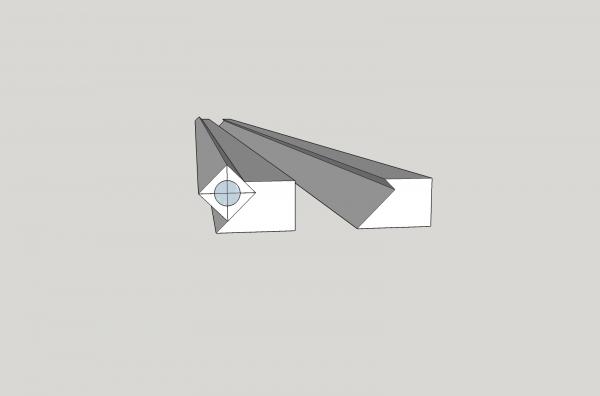
Ordered a set of mast clamps I designed, to be 3D printed. I’ll use these to taper/round the mast and boom for the Carrie Price. They hold the stock at a 45 degree angle, so that I can remove the corners, to bring the square stock to octagonal. For this model, I will round the parts from there, and skip the 16 sided step. The company sent me an e-mail, that the file passed, and that they are printing them. As you can see, I will have to trim the bottom corner of the inserts to allow me to hold the 1/8 inch square stock (see below the insert holding the stock). The other insert is, of course, used to hold the other side of the stock. I also ordered a small wood vise to use to hold the inserts and stock.


-
Well after looking at the 1/64th scale frame and the requirements for the minimum thicknesses Shapeways requires, I don't know that I can 3D print it. I have two options: 1. Print everything with square cross sections, and scrape them to round. 2. Print a pattern to be used as a mold for a RTV jig, to hand build one on. I can't just print the jig itself, all their plastics are porice (sp), and thus would absorb any glue I used while building the frame parts. It also does not have the heat capacity, to be used for soldering the parts. The RTV would allow either option. I might try an experiment with using a wax coating to seal the plastic, maybe a couple layers of future floor polish, would do the trick. I'm going to redraw the 1/32nd parts this weekend.
-
I contacted Shapeways, and found out the trouble with the dredge frame designs. Their page shows limits of .3mm for walls supported on both ends, and .6mm for those that are hanging in mid air at one end. This applies to square/rectangular shapes only! For round cross sectional parts the limits are .6mm and .8mm respectively. I can redo the 1/32nd part, with work, by increasing the smaller 5/8" scale frame parts to about .8", not bad. I just wish I had known this when I started! For the 1/64th parts, I will have to get creative. I think that if I design the parts to lay flat in sections, with the bottom square, I can do it. I will then have to scrape the flat parts of the sections round, like if I was scraping wooden parts to a shape for molding, or other formed surfaces.