thibaultron
-
Posts
2,951 -
Joined
-
Last visited
Content Type
Profiles
Forums
Gallery
Events
Everything posted by thibaultron
-
 I contacted Shapeways, and found out the trouble with the dredge frame designs. Their page shows limits of .3mm for walls supported on both ends, and .6mm for those that are hanging in mid air at one end. This applies to square/rectangular shapes only! For round cross sectional parts the limits are .6mm and .8mm respectively. I can redo the 1/32nd part, with work, by increasing the smaller 5/8" scale frame parts to about .8", not bad. I just wish I had known this when I started! For the 1/64th parts, I will have to get creative. I think that if I design the parts to lay flat in sections, with the bottom square, I can do it. I will then have to scrape the flat parts of the sections round, like if I was scraping wooden parts to a shape for molding, or other formed surfaces.
 -
Well I had disappointing news from Shapeways, they can't print the dredge frames. I did not understand fully their e-mail, but I think that they can not print wire shaped objects, that small. I'll chat with them tomorrow, and see if I can savage any of it.
-
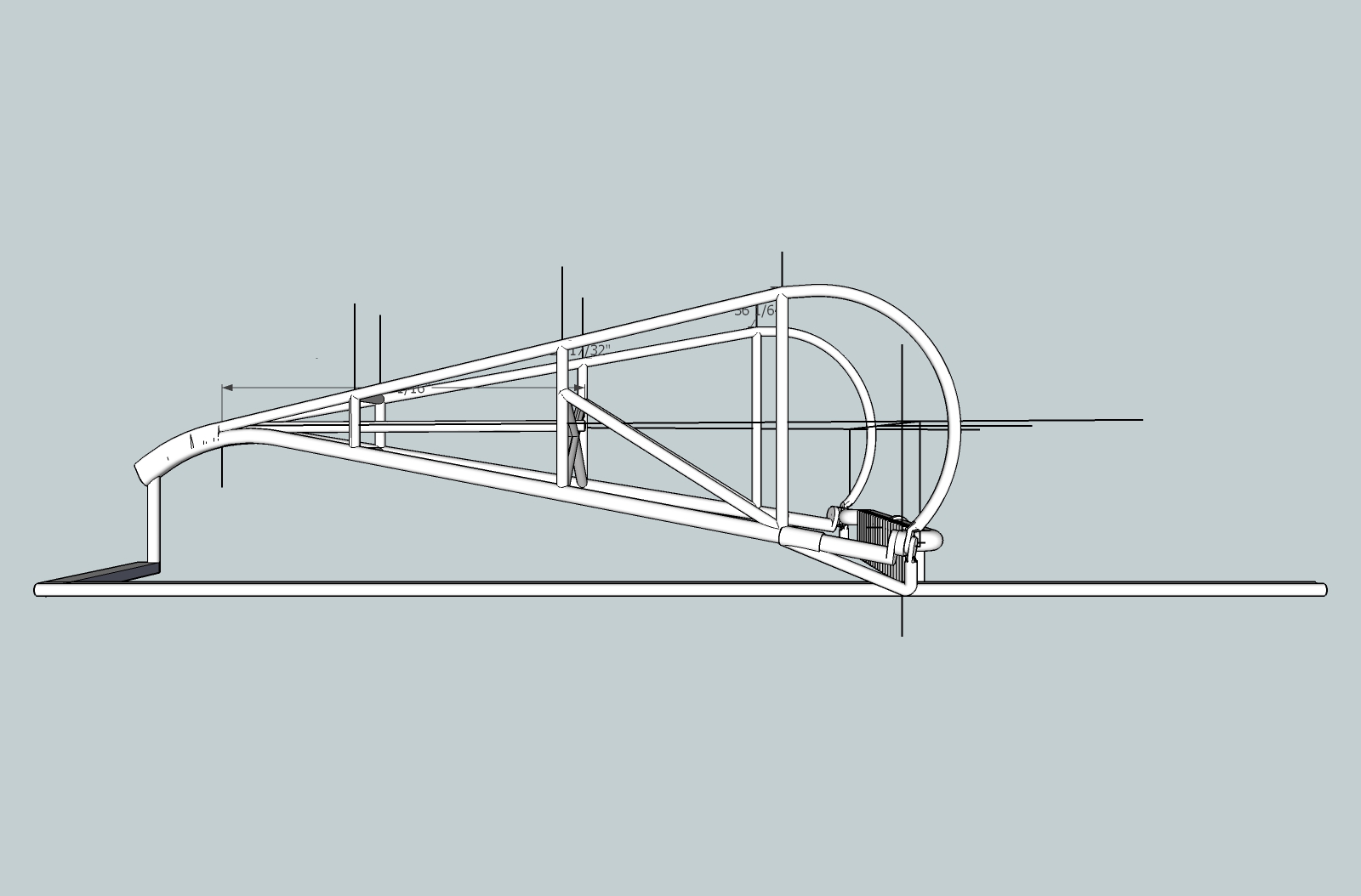
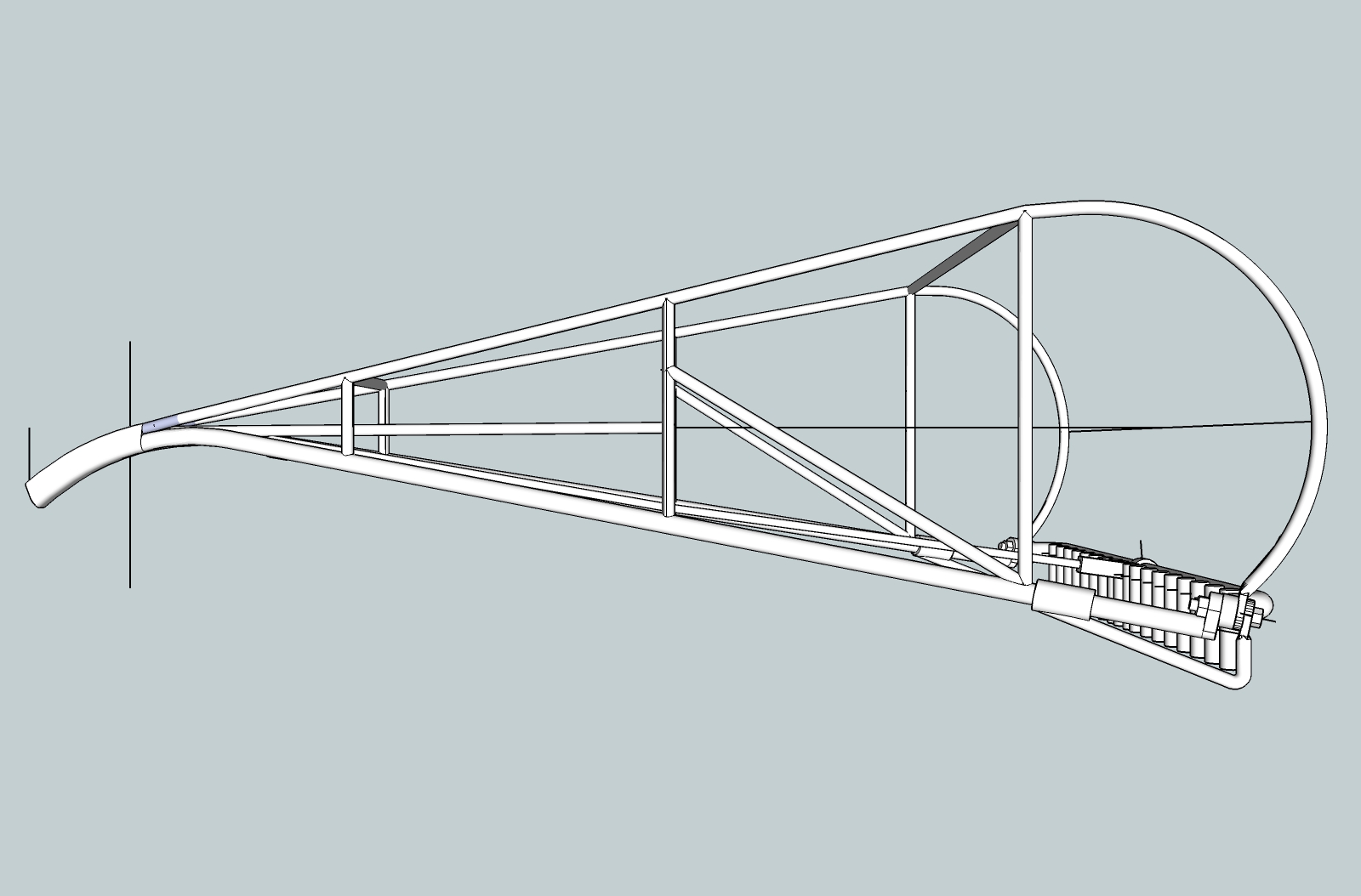
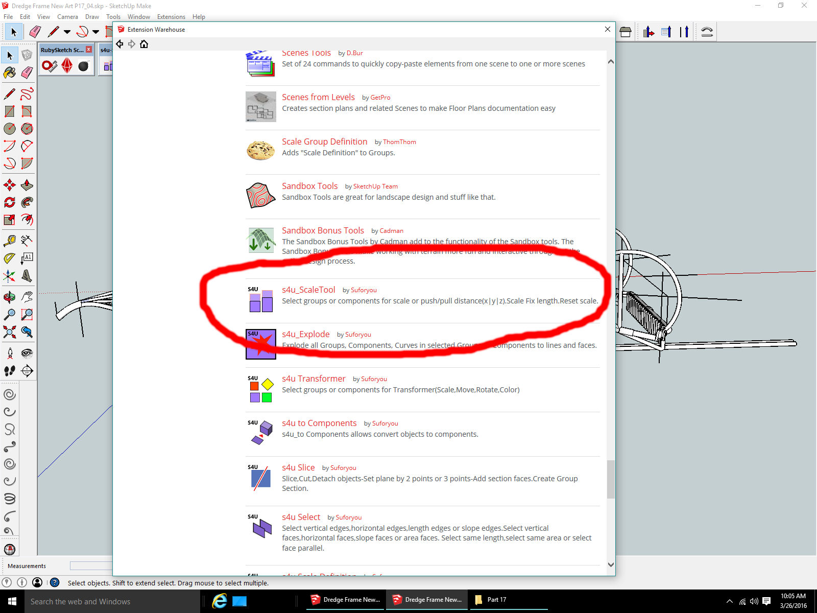
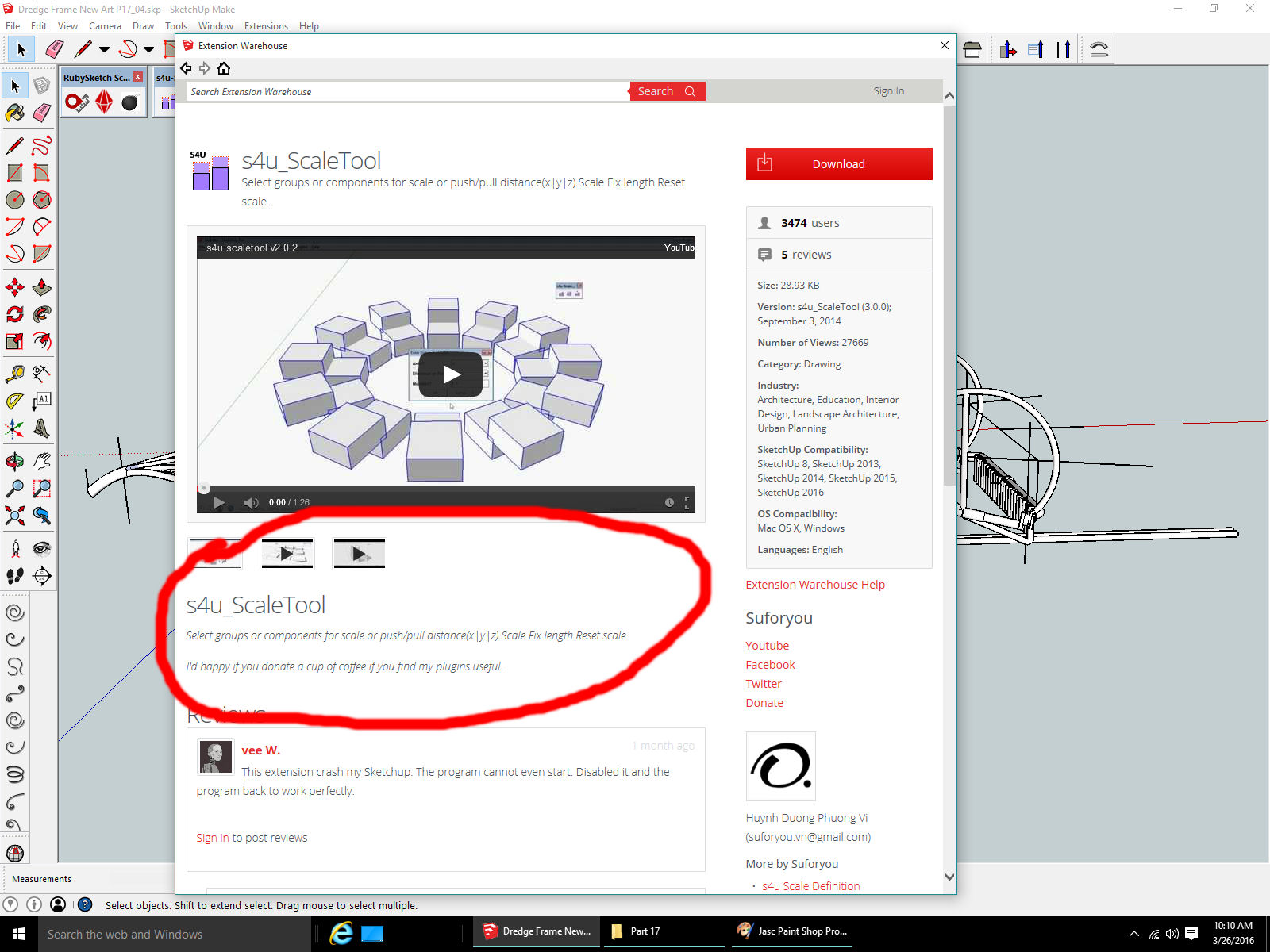
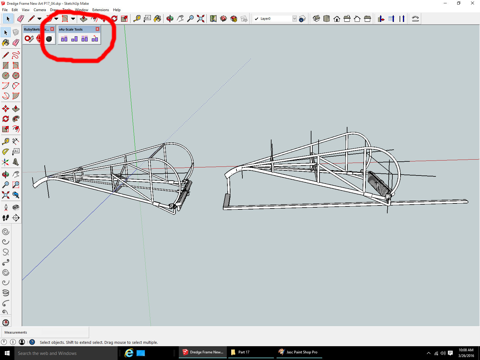
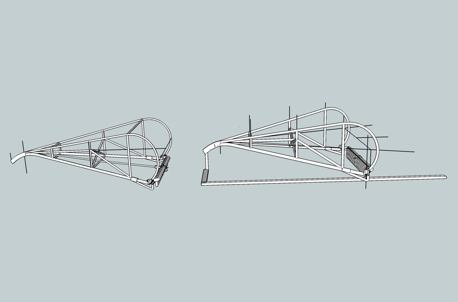
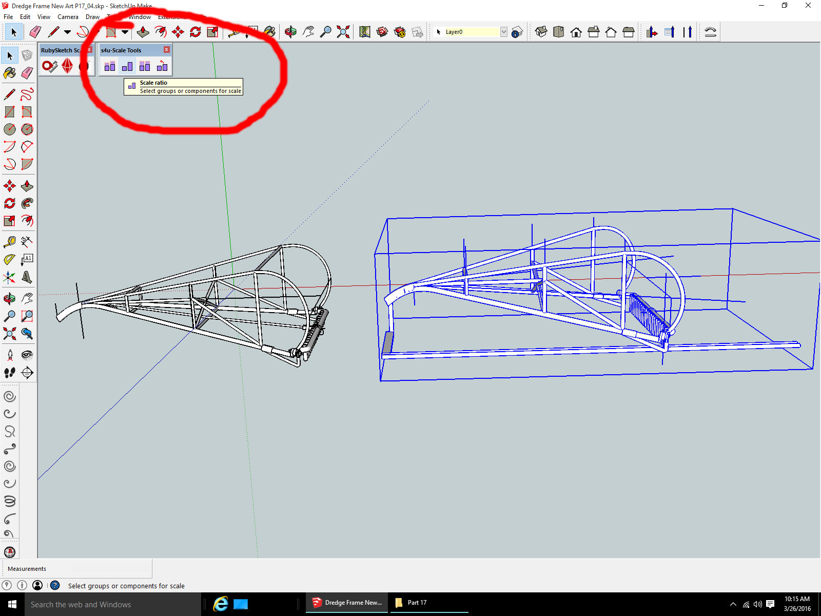
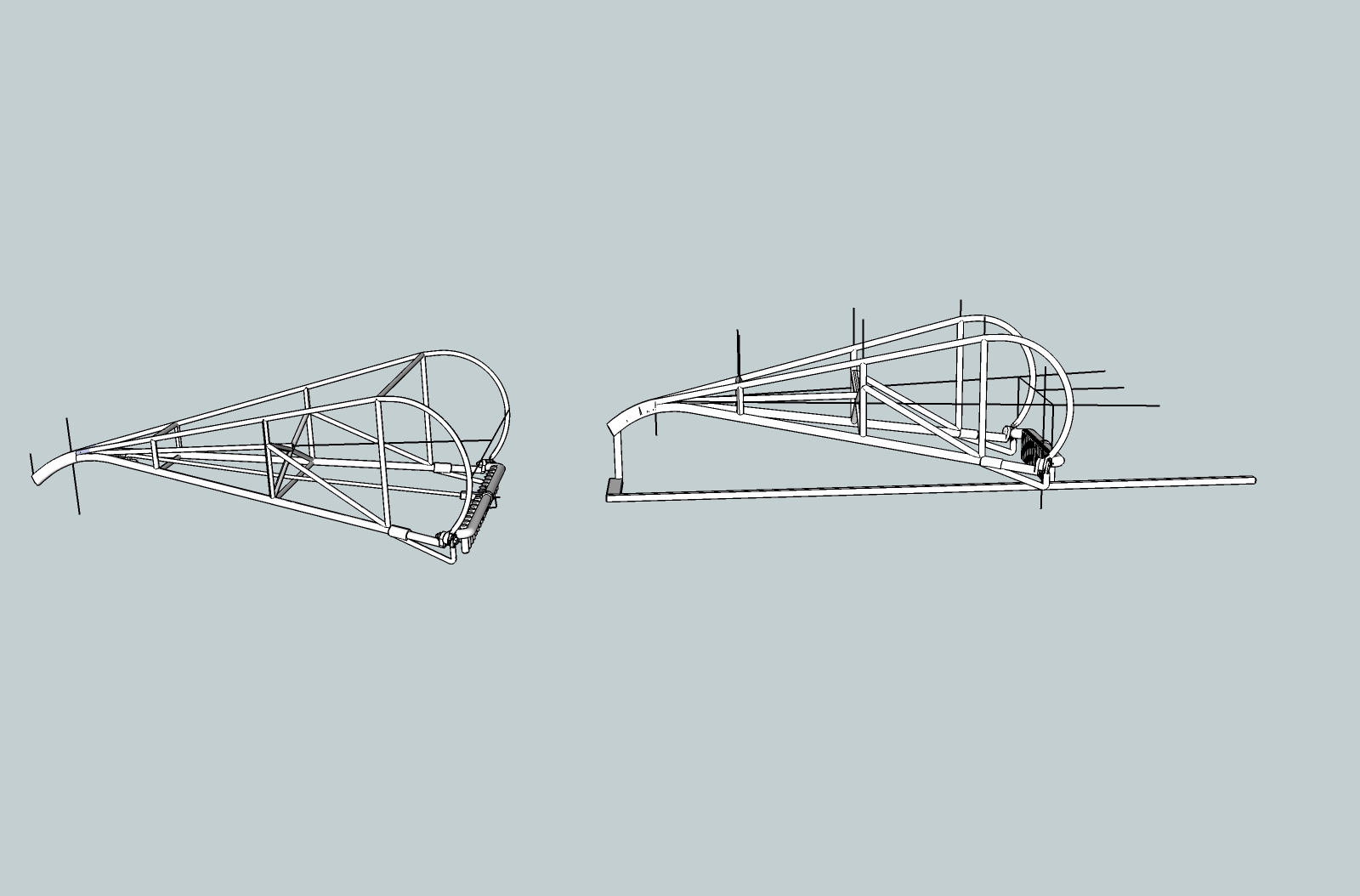
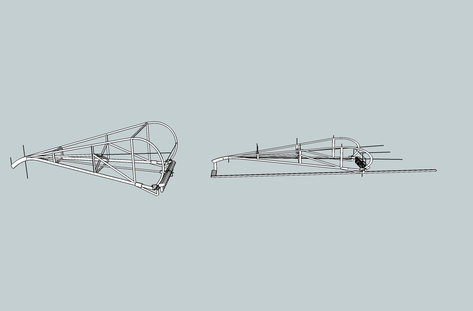
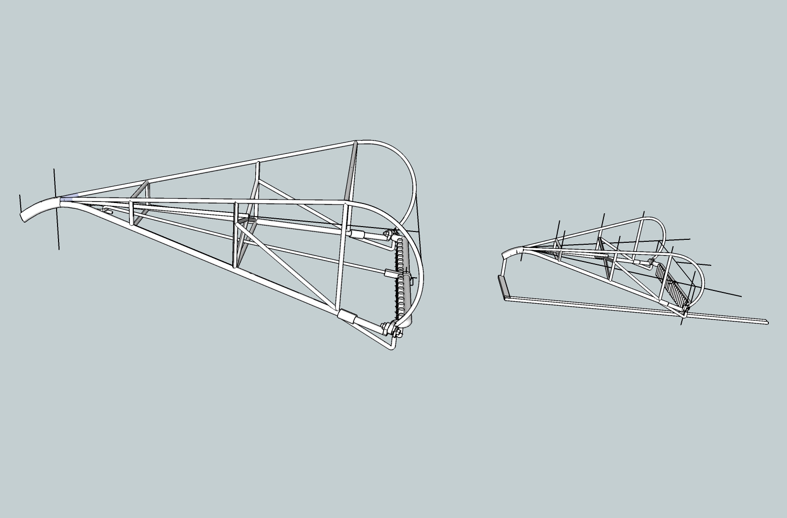
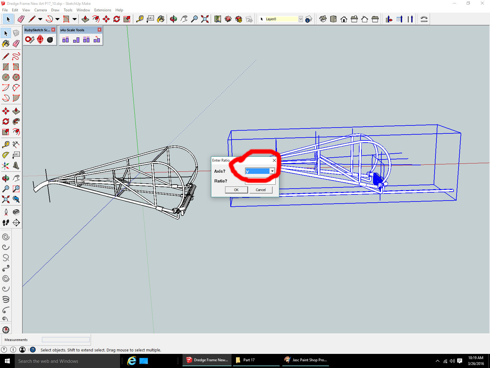
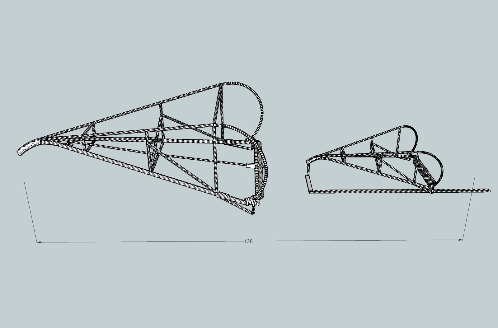
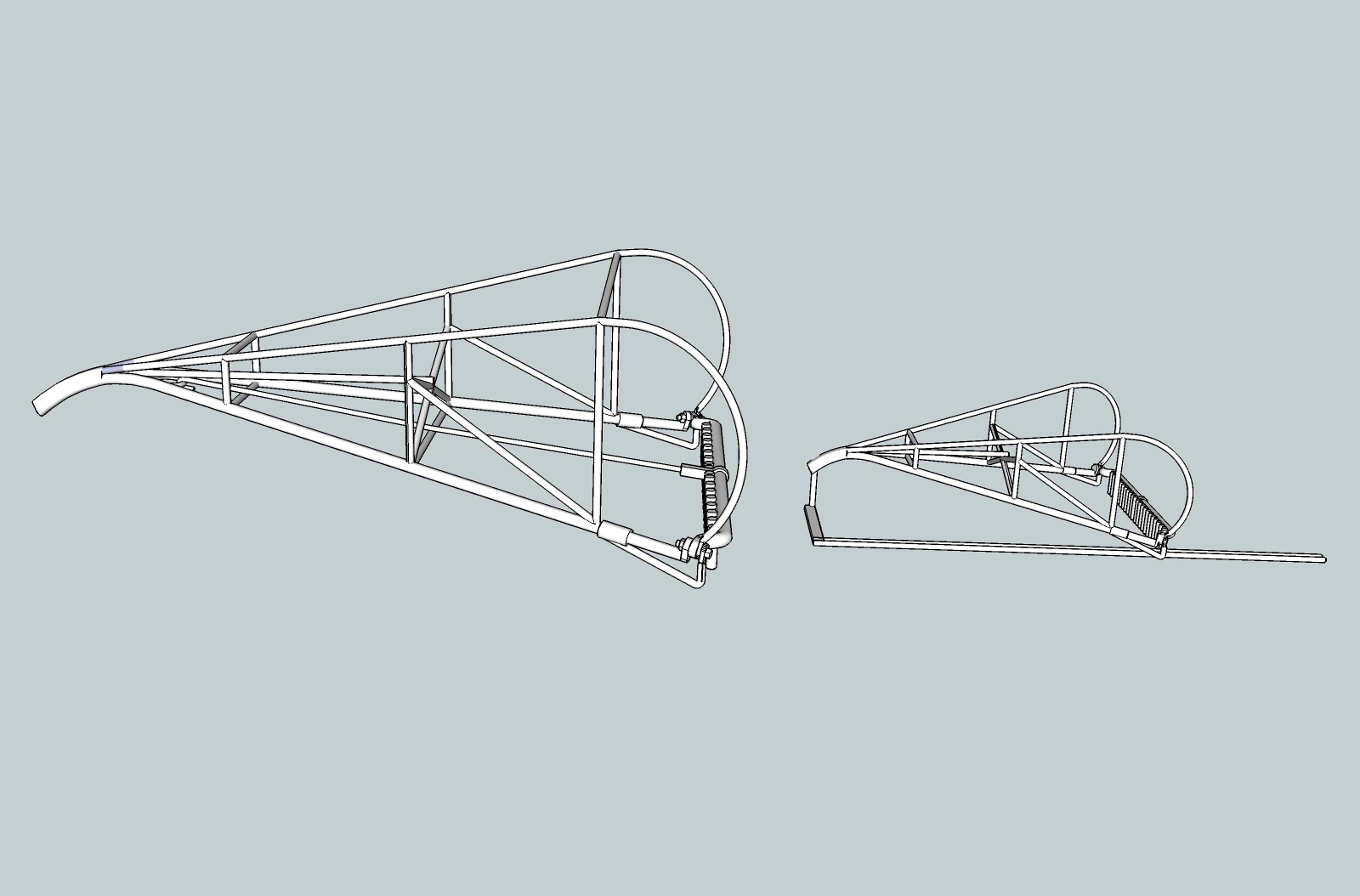
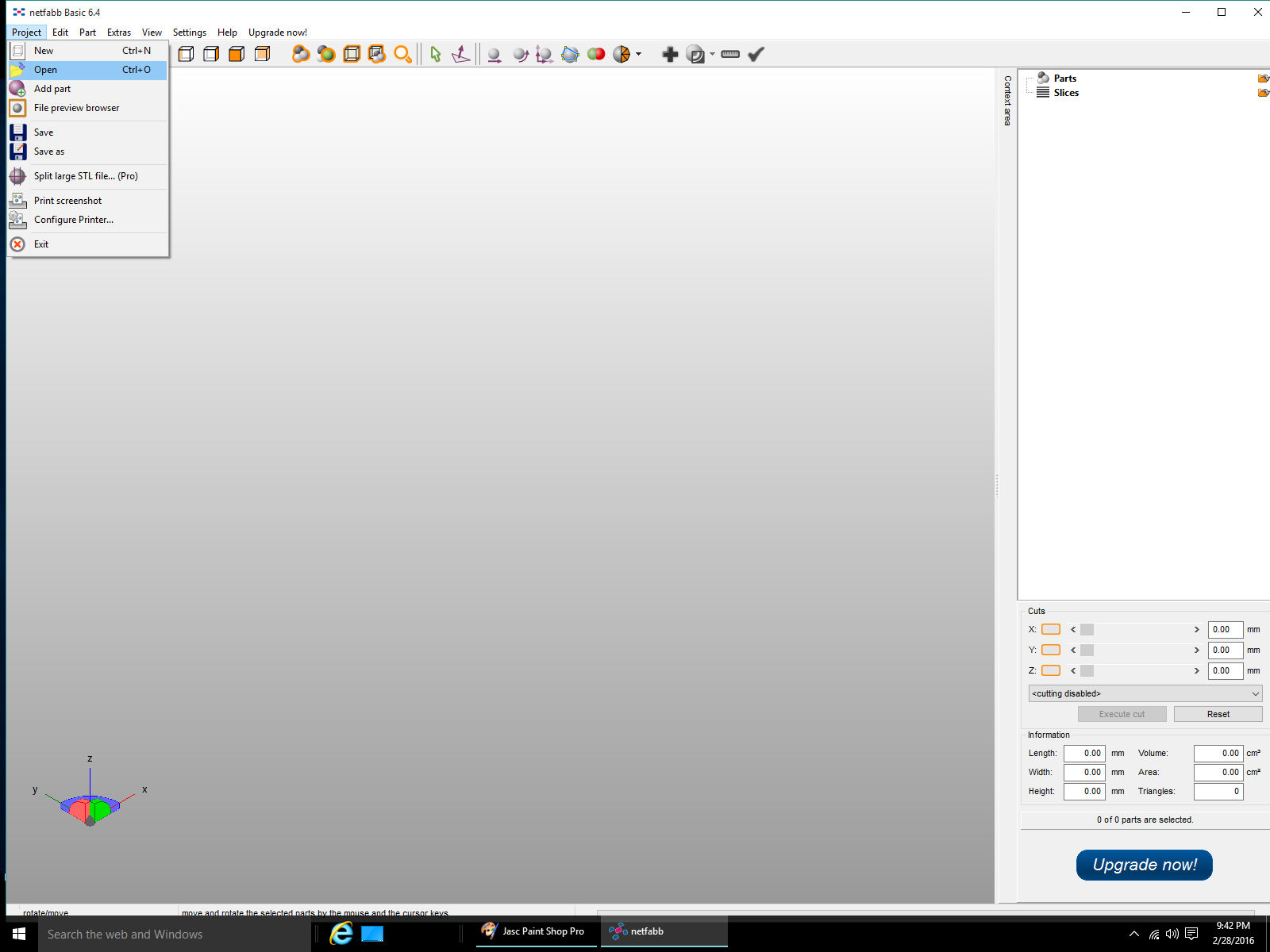
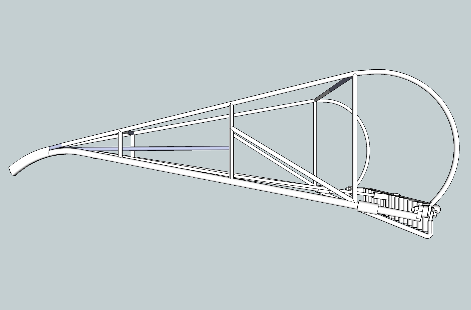
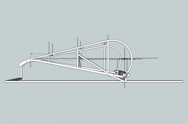
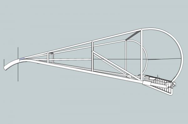
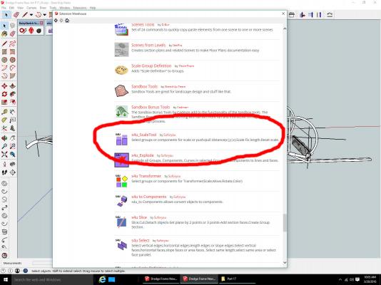
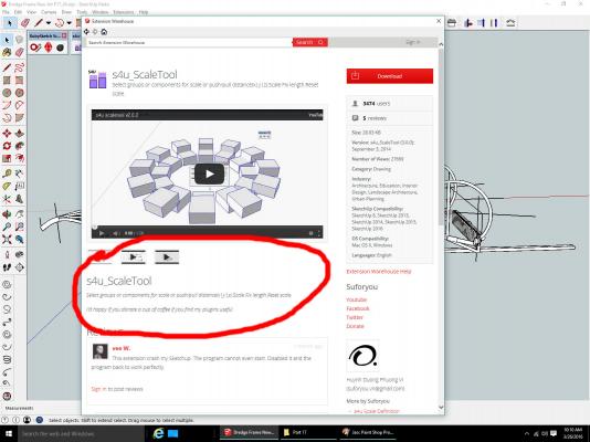
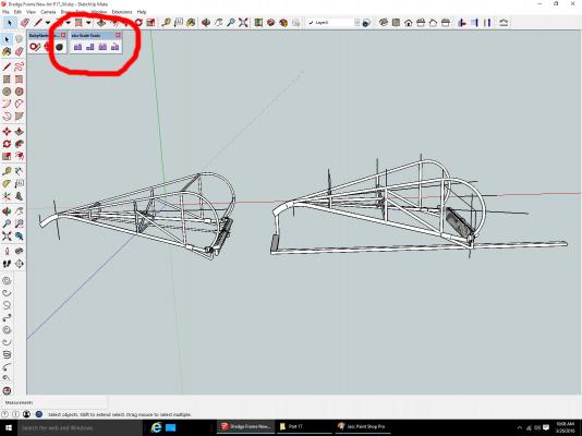
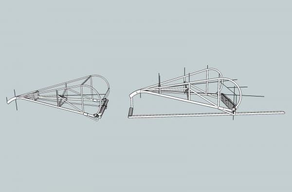
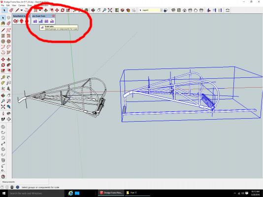
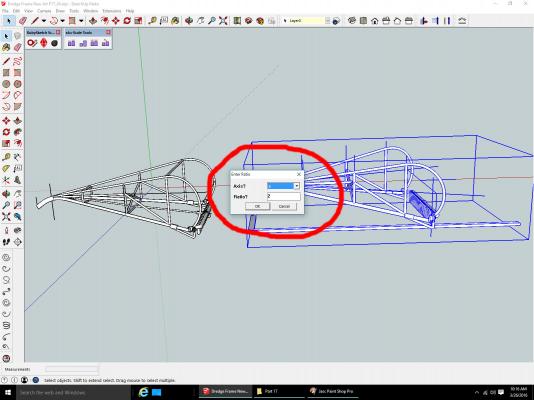
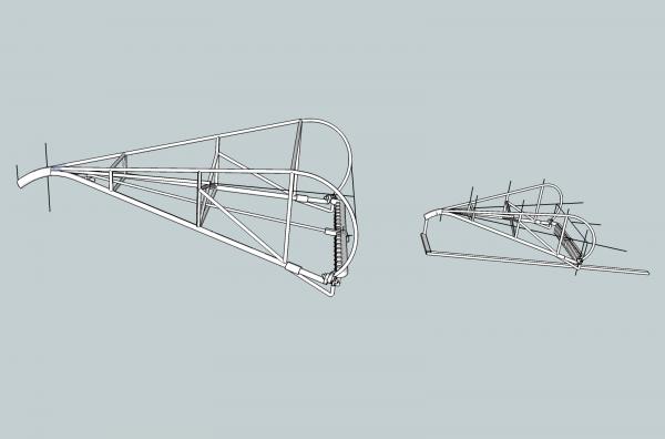
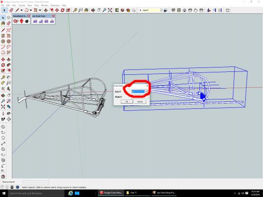
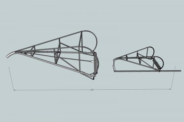
Part 17 Scaling Well, it looks like I may have to continue this thread. I came across a new operation, that will be of interest to everyone. One feature SketchUp lacks, in its native functions, is Scaling of a model. It has a stretch operation, but it is difficult to use, especially if scaling in more than one axis is desired. Now that I have finished both the 1/32nd, and 1/64th scale versions of the dredge frame, I wanted to combine one model of each into a single file, so that I could print a test sample with one of each in it. 1/64th scale version. 1/32nd scale version. Looking through the available extensions/plug-ins, I found one that suits the bill! s4u_ScaleTool. This plug-in lets you rescale your part, by Distance: Push/Pull with mouse, or you can enter the distance value, like when drawing lines and figures. Ratio: 2 – twice as big, 0.5 – half size. Fixed Length Reset Scale. You can only scale one axis at a time, but the function lets you select which axis, so you just have to do it three times, once for each axis. This gives you consistent results, which is much harder to do with the stretch function. After installing, the menu below will be added: Here is the drawing with both models combined into one file. As both parts were originally drawn full size, both are shown the same size in this drawing. I need to make the right hand part, the one that will be 1/64th scale, half the size of the 1/32nd scale part on the left. I will be using the Ratio function. I have not used the other types, but you can experiment with them. So, I selected the right hand part, for shrinking, then I selected Ratio (second from left). The following window pops up. The default is 2, twice the original size, and the Z Axis for the operation to be performed on. I entered 0.5, and hit OK. The part is now 50% thinner. Next I repeated the scaling, but selected the Y Axis. And finally the X Axis. The right hand part is now the correct size, in proportion to the left hand one. After some clean up and aligning the parts so they are in the same horizontal plain along the bottom, I have this, the file I sent to the printer’s. I also moved the right hand part so that the far end of the two horizontal bars, are 128 inches from the front most part of the nose on the left hand part. When I scale the parts at the printers, the total length will be 4 inches, using 1/32 as that overall size. This gives me a 1/32 left hand part, and a 1/64th right hand part. I’ve sent the file to the printer’s and I’m waiting to see if it passes their manual check. Even if it doesn’t, I’ll still have it printed, to see what it looks like, then make the corrections needed. I think the 1/32nd part will be Ok, the 1/64th may need changes.

-
3D Printing - Not Just Yet!
thibaultron replied to dvm27's topic in CAD and 3D Modelling/Drafting Plans with Software
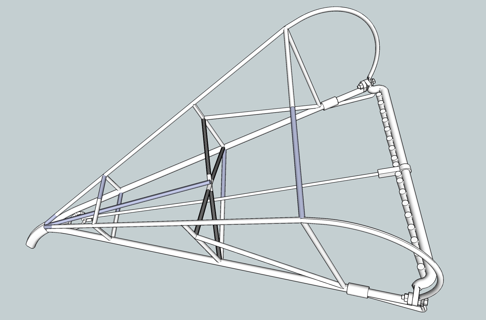
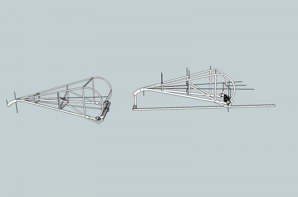
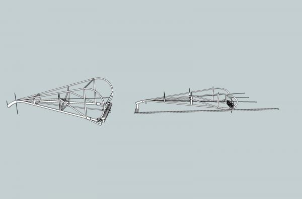
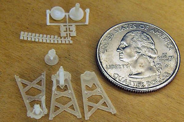
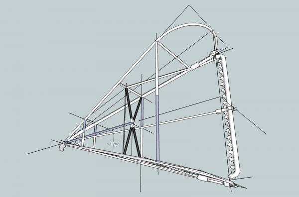
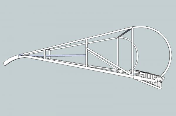
Here are two parts I just sent to Shapeways as samples, to see how they come out. When I get them back, I may have to make changes for the final versions. These are Oyster Dredge Frames for 1/32nd and 1/64th scale Chesapeake Bay Skipjack models. The smaller for the Lindberg kit I'm presently building, and the larger for the MS Willie Bennett, I will start soon. The upper frame bars on the smaller model, are the minimum 0.3mm wall thickness standard, as is the brace running along the bottom of the 1/32nd frame, from front to back.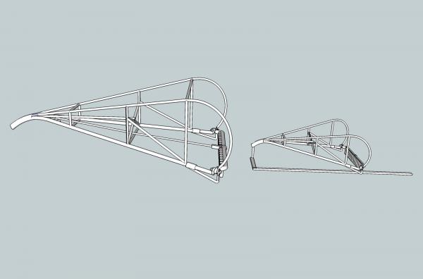
-
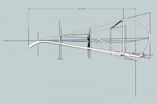
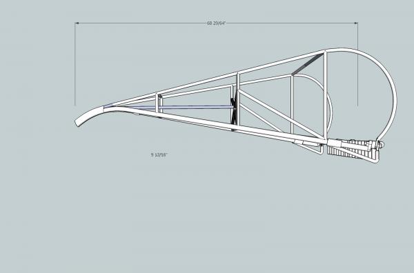
Part 28 I finally finished the drawings for the dredge frames in 1/32 and 1/64th! I just sent a sample off for printing. I assume I’ll have to make some changes once the sample comes back. The 1/64th model is pushing the 3D printing to the limits of Shapeways standards. The smaller 1/64th model, had to have some changes, over what I did for the 1/32nd one. The horizontal cross braces were too thin for printing (not sufficiently supported), so I printed the two horizontal bars, too be used as stock for adding them, when I build the frames. I’ll have to fabricate the bottom brace from wire, It was far too thin to print, without being far too large proportionally. I still have a couple details to add to the 1/64th model, but will wait to see how what I have now turns out. I also added a support/sprue at the nose. The two bars run between the outer skid, and the first dredge tooth on that side. I may have to add a support for the nose of the 1/32nd part. It may help with the printed shape of the part (orientation of the bar to print path). They may lay the part down with the nose on the table for printing, without the support. I ordered the prints today, and should get them back mid April. I’m drawing some detail parts to use for cleats, etc., to see if they can be printed. My hands are a lot shakier now, than they were 40 years ago, so making really small parts is difficult, some times. Now that my shop is somewhat back in order (well at least I can get to the work bench), I can soon start back on the model.

-
3D Printing - Not Just Yet!
thibaultron replied to dvm27's topic in CAD and 3D Modelling/Drafting Plans with Software
The same material I used for my winch parts. -
3D Printing - Not Just Yet!
thibaultron replied to dvm27's topic in CAD and 3D Modelling/Drafting Plans with Software
What printer/service did you use? Nice clean prints! -
3D Printing - Not Just Yet!
thibaultron replied to dvm27's topic in CAD and 3D Modelling/Drafting Plans with Software
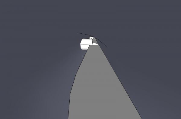
If you go to the end of my 2D to 3D tutorial in my signature, you can see the results of my 1/32nd and 1/64th scale dredge winches, that I had 3d printed. The prototype winch was 36 inches tall from the base to the drum axle. -
DIY Bandsaw Wheel Brush
thibaultron replied to grsjax's topic in Modeling tools and Workshop Equipment
Thanks for the link! Great idea. -
Anyone know how to contact the Moderators?
-
http://www.ncdcr.gov/press-release/significant-civil-war-era-shipwreck-discovered-nc-coast
-
- 1
-

-
https://www.thevintagenews.com/2016/03/03/revolutionary-war-era-ship-found-at-the-site-of-virginias-first-city-alexandria/?src=fba&type=wca&page=tvn
-
- 3
-
-
Your welcome. Now I can get back to building the model they were designed for. Finally at the point I can move my workbench Model Railroad layout combo into the new section of the shop, and start using the workbench again.
-
Whaleboat kit - Amati vs Model Shipways vs Blue Jacket
thibaultron replied to ArtB169's topic in Wood ship model kits
Found the article on the Morgan whaleboat. http://www.thenrg.org/resources/The_Journal/574/57-4%20NRJ%20Morgan%20Whaleboat.pdf -
Whaleboat kit - Amati vs Model Shipways vs Blue Jacket
thibaultron replied to ArtB169's topic in Wood ship model kits
The Charles Morgan whaleboat does have a build log on this site. -
Whaleboat kit - Amati vs Model Shipways vs Blue Jacket
thibaultron replied to ArtB169's topic in Wood ship model kits
The Amati kit and the Model Shipways kit are of two different styles of whale boat. The Amati is not of a boat use on a larger sailing ship. It is a model of a Tancook Whaler, a type of fishing boat use on Tancook Island in Canada. The Model Shipways kit is of a different style, used on those larger whalers. Artesania Latina makes a kit of a boat also used on larger sailing whalers, in this case specifically the Charles W. Morgan, a ship that still exists in the Mystic Seaport Museum. Both the Artesania Latina and MS kits are models of actual boats used. I'm not sure if the Amati kit is from a real boat, or only of the general type. The Artesania Latinai kit has some mistakes in its design, as compared to the boat used on the Morgan. The hull and most of it are correct. I can not remember the article exactly, but the biggest mistake is the shape of the rudder. I think the build log is on this site, but an internet search should find it. This kit is actually less detailed than the MS kit. If I remember the build correctly, the author added a lot of scratch built details. The MS kit comes with an entire bound printed step by step book, on building the kit, not just their normally good stapled instructions. I have the Amati kit, the Artesania Latina kit, and in the past have had the MS kit, which I stupidly sold. The MS kit is much better. Both Artesania Latina, and Amati are known for questionable historic accuracy, but the Artesania Latina, is very close, and the Amati looks to be quite close to drawings I have seen in Chappele's books. From what I can see of the Bluejacket kit (I really wish they had more and larger pictures of their kits), it looks to be excellent also, but I have not seen the kit in person, only web pictures. They have an excellent reputation, and I do own some of their kits. If you want a model of the boat used on the Morgan, go with the Artesania Latina kit, otherwise, I would go with the MS kit. If you want one of the Tancook type, the Amati is the choice, but will need detailing, on the interior. Looking at the MS and BJ sites, the MS kit is 24" long 1/16 scale. The BJ kit is 10" long and 1/32 scale (it says 1/3 scale, but I doubt that the real boat was only 30" long). As both kits seem to be assembled stick by stick, I'd again recommend the MS kit, there is a lot of very small pieces in both, and the larger kit would make it easier to handle those parts. Depends on your skill level, desire for a challenge, and display space. The Artesania Latina kit is 1/25 scale, according to the article I saw. Depends on which site you look at, and the actual scale is not listed on the box. The Amati is also about 1/24, or at least falls in that range according to the general dimensions for this type. The two US manufacturers have a much better reputation than the other two. I normally avoid the European manf. but bought those kits after checking to see if they were accurate. -
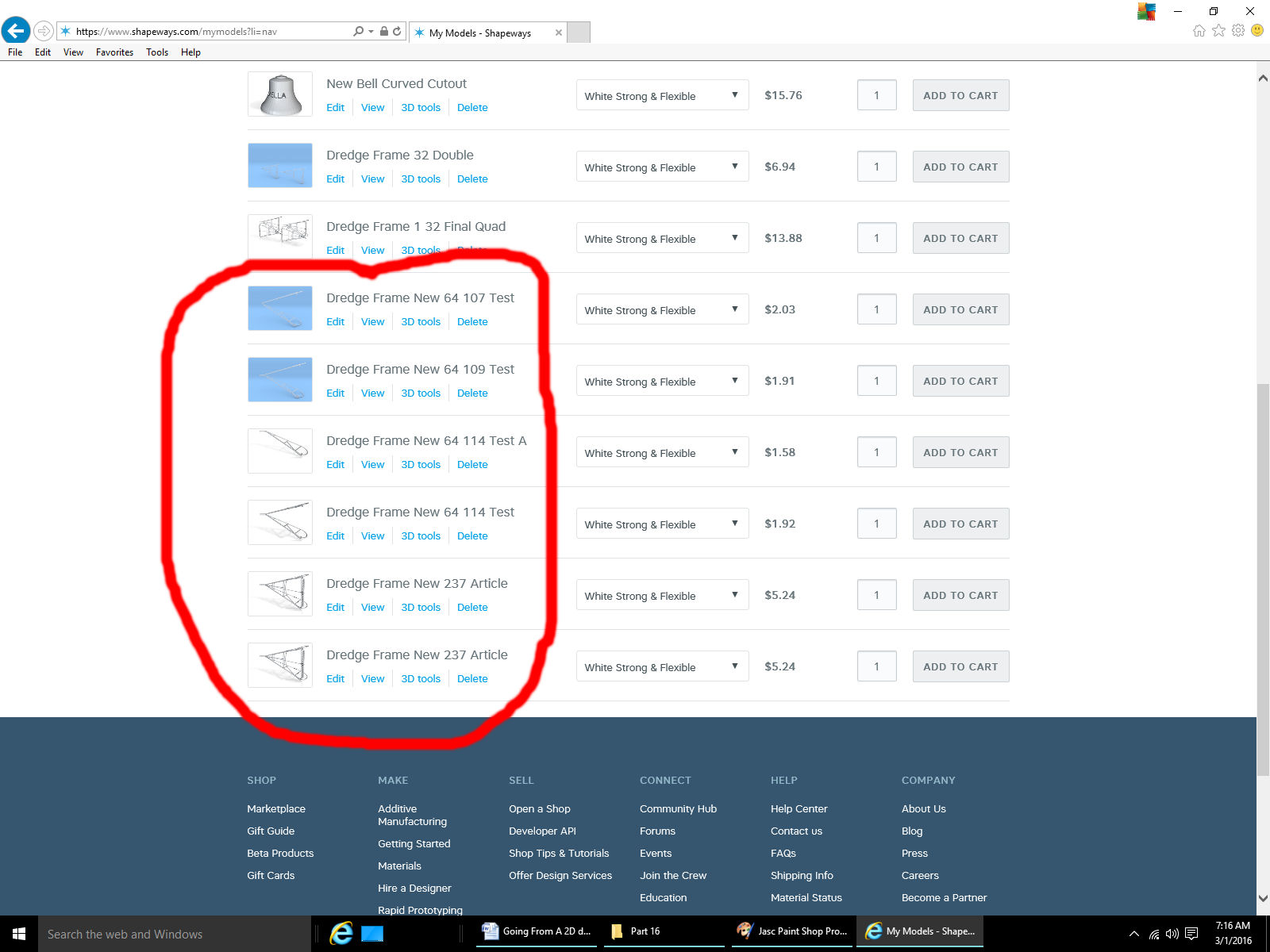
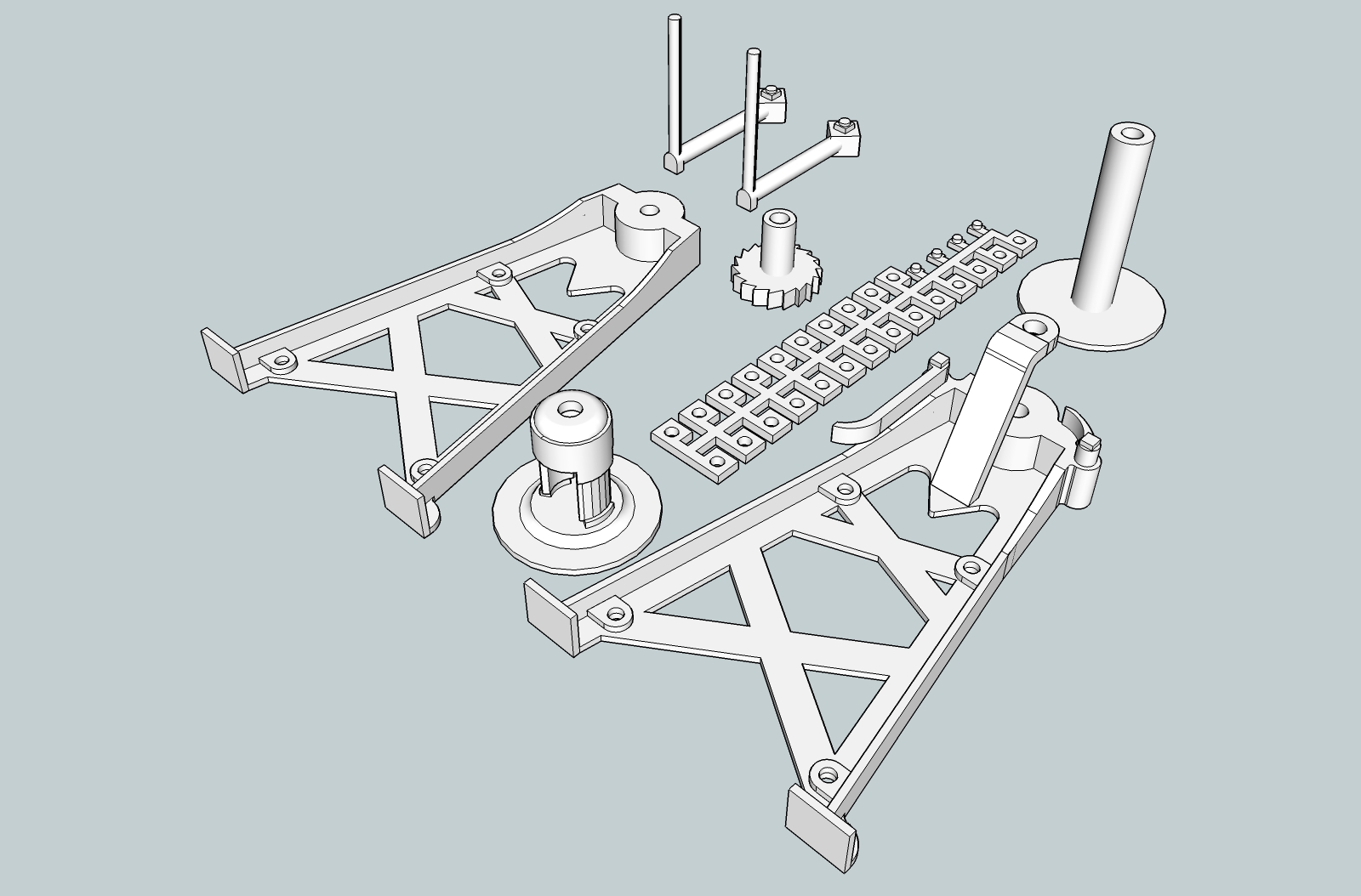
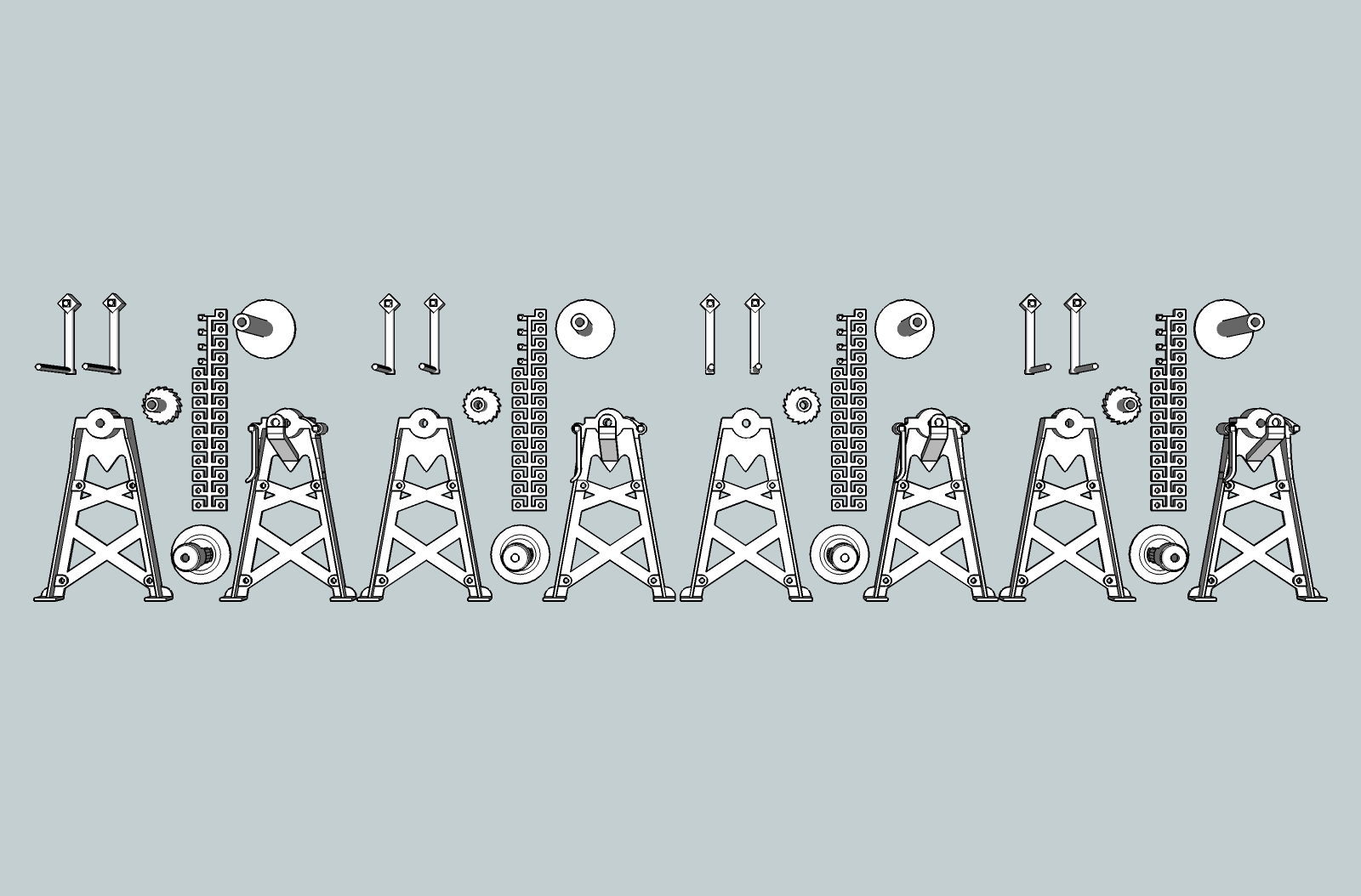
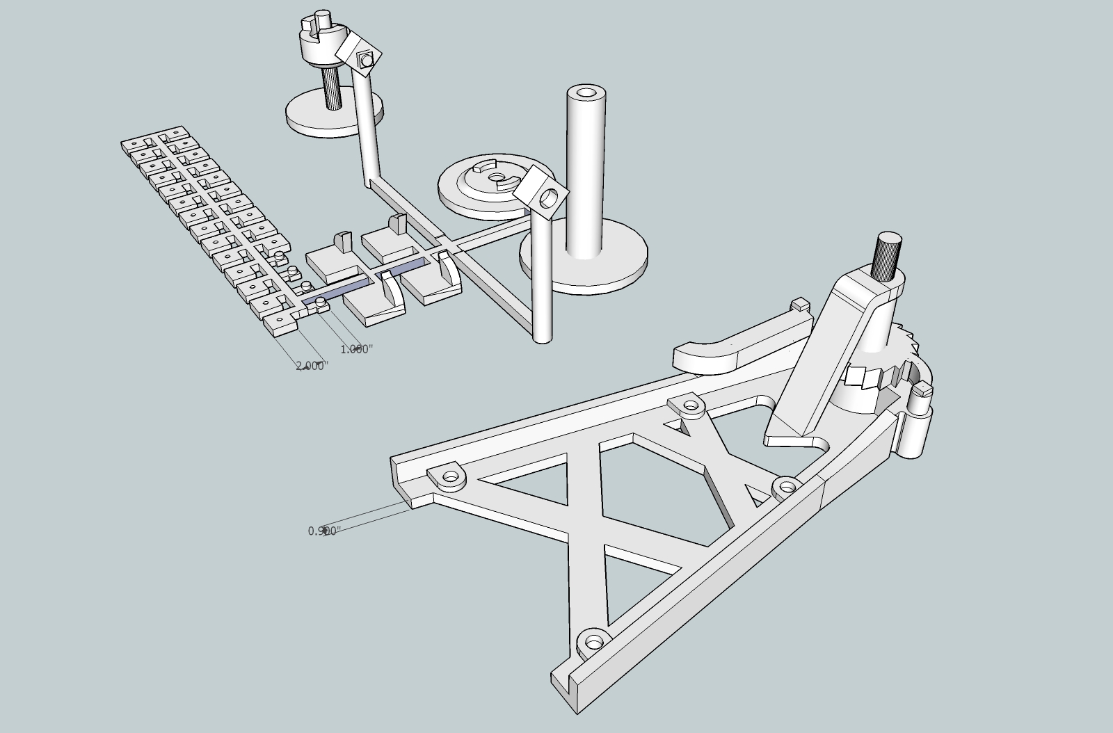
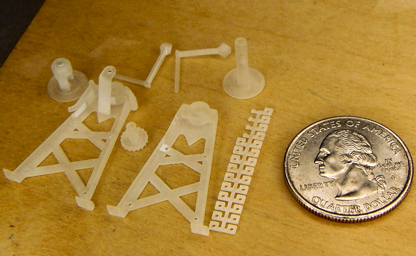
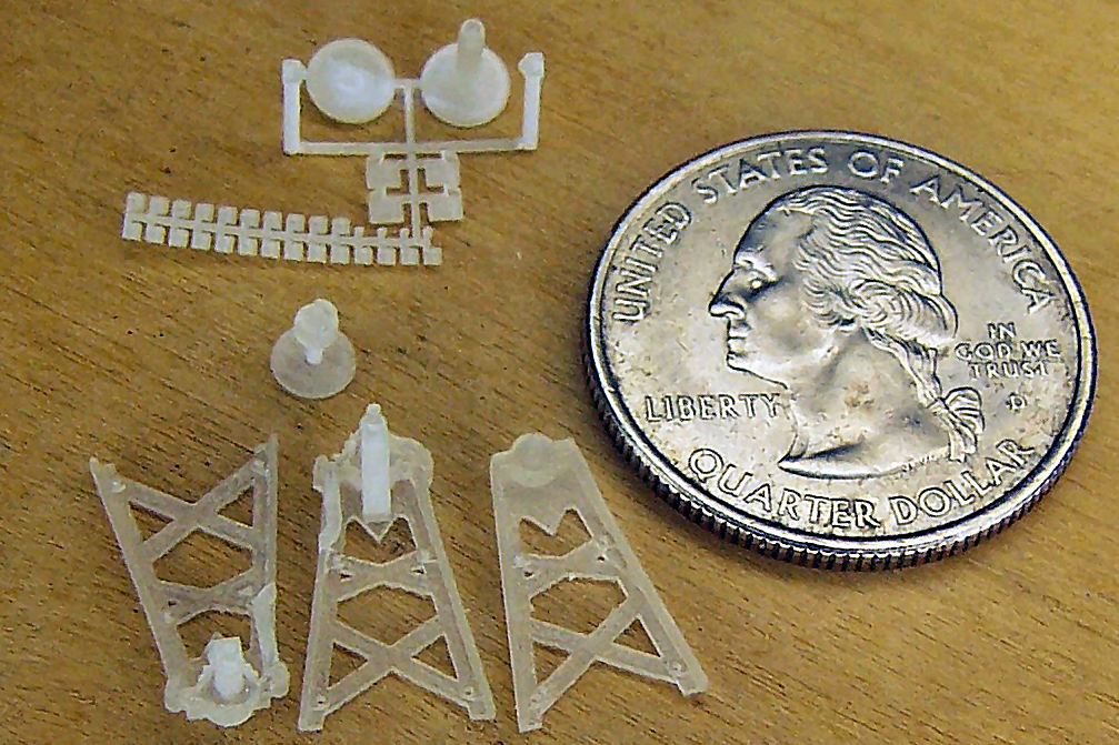
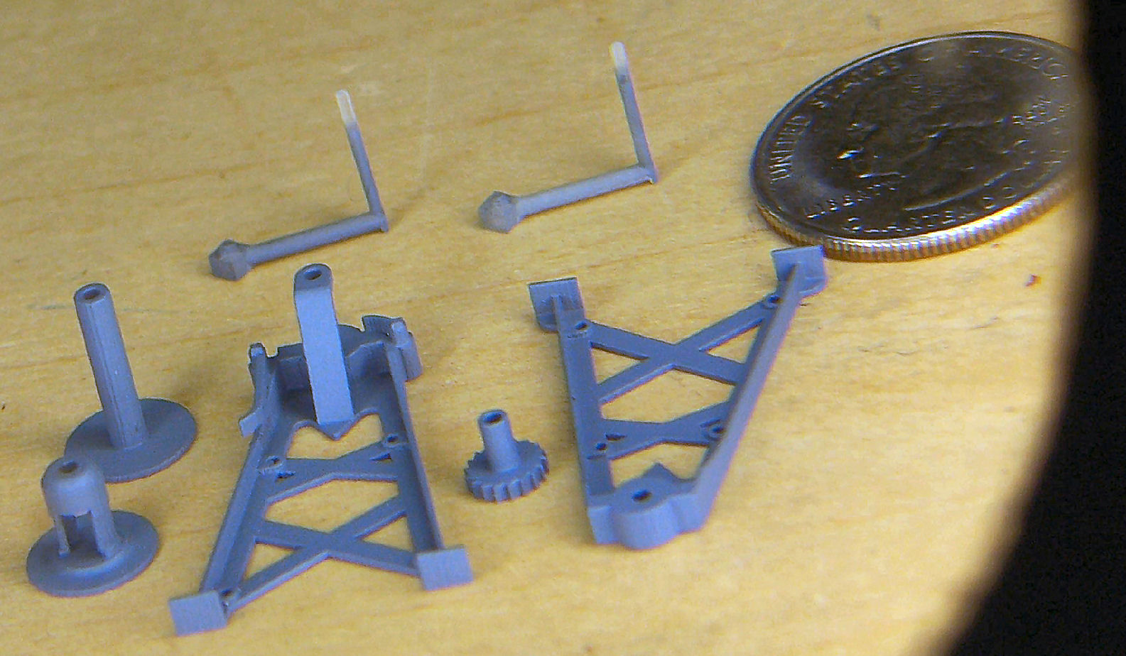
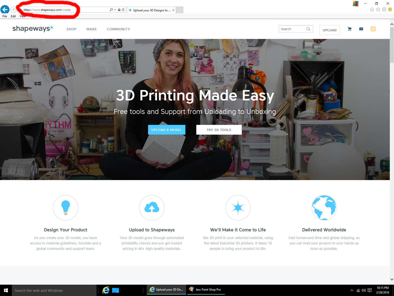
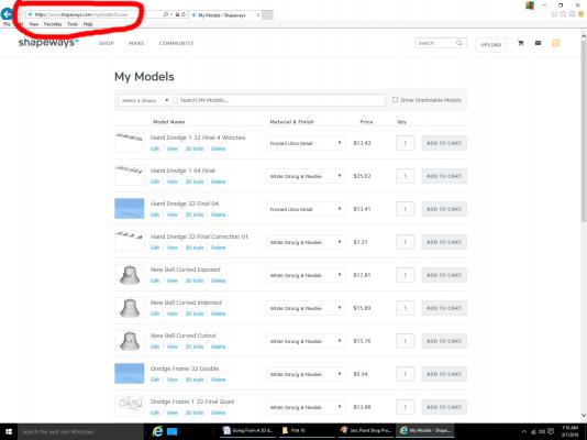
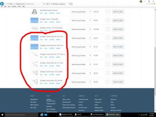
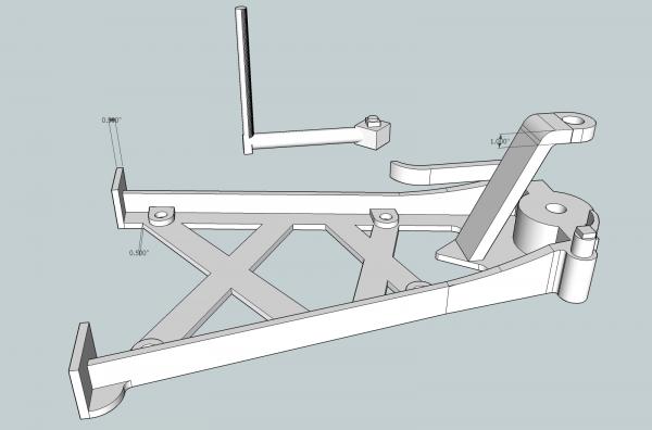
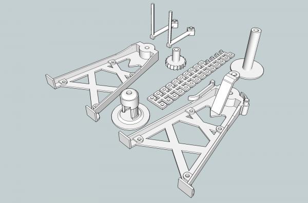
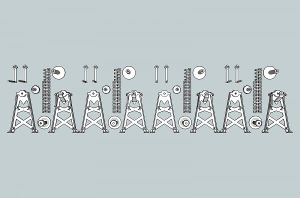
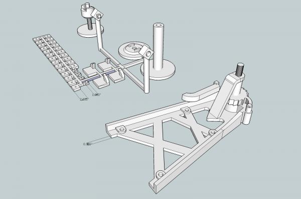
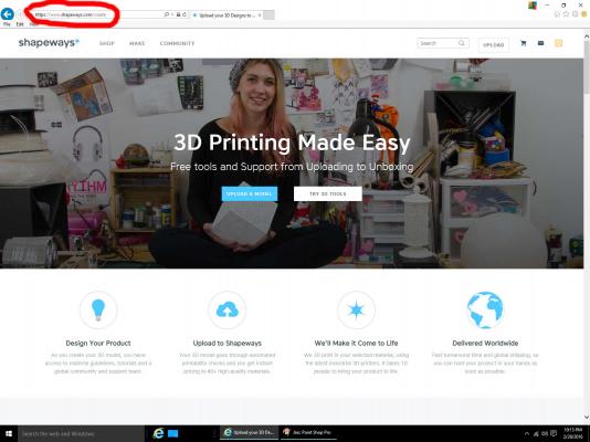
Part 16C As I mentioned earlier, Shapeways has a page that shows all your models, so that you can order more parts, and you can also make your models available to the public. I am not sure what the later entails, maybe a subject for a future post. Here is a sample of my page, with the address highlighted. The page is a private page that I have to log into, in the future I plan to make some of these public, but that will be a while. You will get your own page, once you start submitting projects. Every time you upload a file, it will be placed on your models page, so you will have to periodically clean out your test files. You can see some of the files from making this article, and some from my ongoing 1/64th scale version. Notice that if you submit the same file, with the same name, more than once, you will get multiple instances of it in your model list (last two entries in this list). Be sure to name your final file a unique name, to avoid confusion. What do the particle limits on minimum printing thicknesses mean on a model? On my 1/32nd scale winches, the minimum is a little more than 3/8” in full size. For my model I choose ½” thick webs on the legs (vertical and horizontal). The free standing gear brace is 1” scale thick. It could have been printed as thin as about 0.8 scale inches, if necessary. The crank handle also shown below was able to be printed with scale 1 ½” diameter handle shafts and 1” diameter handles. For the 1/32nd scale parts I was able to print them as separate pieces, except for the nuts which I had to put on a sprue, and the end of the drum and the clutch. These parts were too small to print individually. The large nuts are 2” square, with a 1” diameter hole (scale sizes). For the final printed version, I combined four winches into the file for printing. This cost little more than printing 2 winches (number required for model), and allowed spare parts when assembling the winches for the model. This turned out to be a good move, as one of the crank handles vanished into the black hole in my floor, while I was priming a set for the pictures in this article. For the 1/32nd scale winches, I will use drill rod for the axles and support rods. On the 1/64th scale winches, the drum axle is printed into the parts, and drill rod will be used again for the support rods. I had to make some compromises for the 1/64th scale parts. The minimum web thickness for the legs had to be increased to 0.9” and the one handle attached to the complex leg had to be made thicker. I increased to thickness on the outside edges, to make it easier to sand them down closer to scale. I also had to attach the rest of the smaller parts to a sprue. Even in this small size, I was able to put a hole in the larger nuts. It is under size, but will serve as a drill guide for bringing them to the needed scale 1” diameter. The axle shafts are printed as part of the assemblies, and the gear is attached to the leg. Attaching the gear still allowed for printing it the scale size. The feet for the legs are separate parts here, this makes sanding to thin the leg webs, later, easier. The drum parts, back of the legs, and the handles have recesses in them to fit the printed axles. Yes, one leg is missing; I deleted it from the drawing, so that the remaining parts could be displayed larger. This ends this series. I hope that some of these hints will help you in your endeavors. For those of you who may want further explanations, of how I drew the parts, and the history behind them, check out my Carrie Fisher build log. Feel free to ask questions, or if you run into a problem drawing your parts, maybe I can help.
-
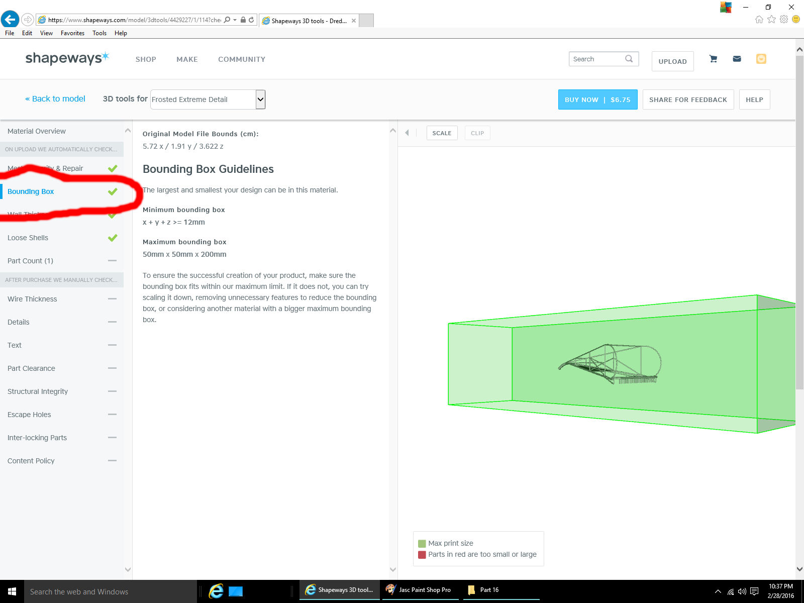
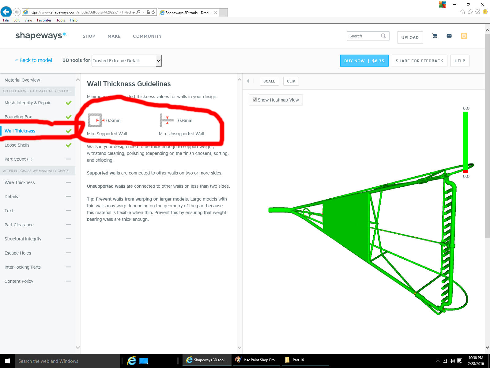
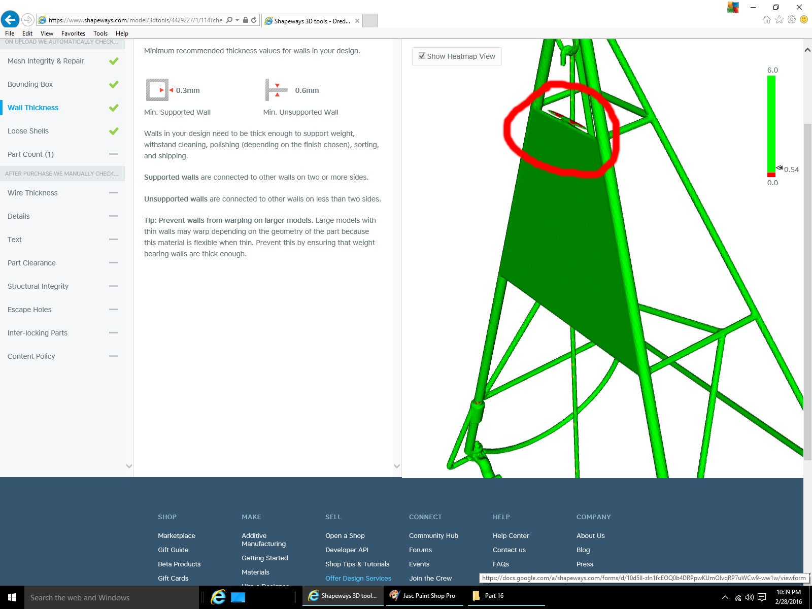
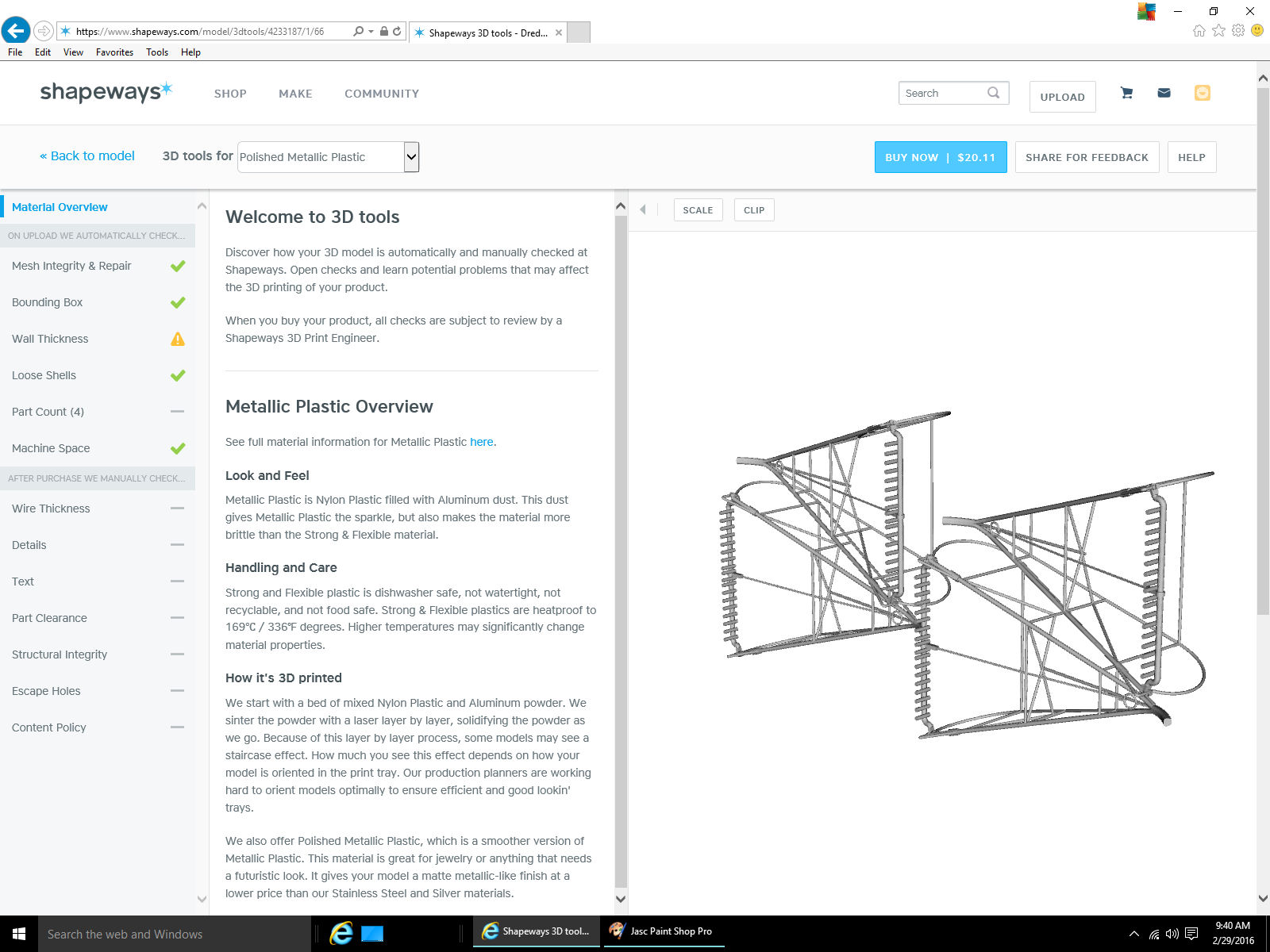
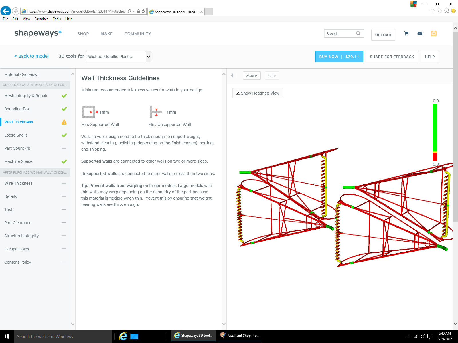
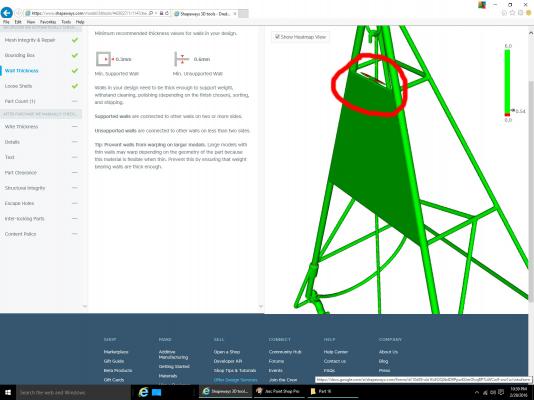
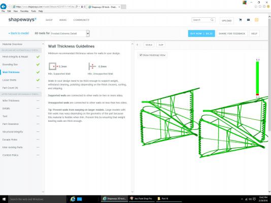
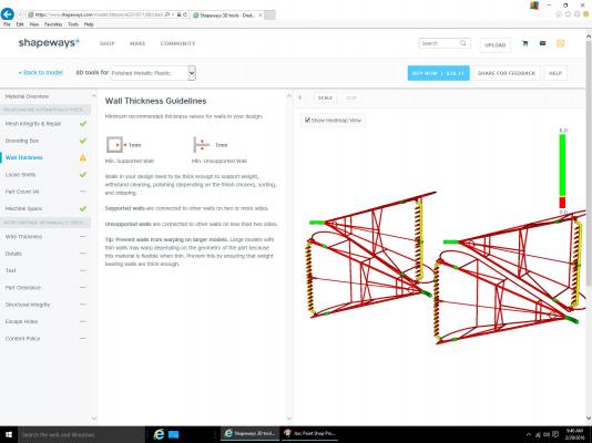
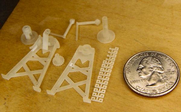
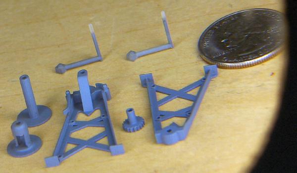
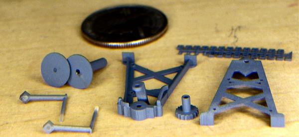
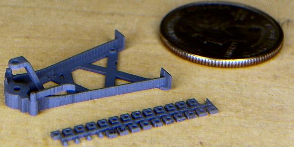
Part 16B One thing that can keep your part from printing, is that it is too big to physically fit on the printing bed. The Bounding Box requirement is what determines this. Selecting that text will display your part, as it will fit inside the machine. At least most of the time the box will be shown, if not, you just have to check which of the axis may be too long, if the check fails. Another Bounding Box problem may be that there are parts, in the file, that are too small to be printed individually. I discussed this in an earlier section. If you will be printing multiple parts in the same file, looking at this will show you roughly how many you can fit in one print. Each file that you have printed has a $5 setup fee, so if you can fit multiple parts in each file, you only have to pay for the additional material costs. Now we need to check the Wall Thickness requirement, before we try to print the part. Select that text and the window below will be displayed. The minimum thickness limits are shown, as well as a graphic of the part. Green means good, but we need to inspect it closer. For one thing that sheet on the bottom is back. This will have to be corrected before the final part is ready. Looking more closely at the part there is another problem. There is a defect at one of the braces, shown by an extra nub/flash on the brace, and the red color. The red means that the part may be too thin. All these are probably caused by those interior walls. After cleaning everything up I came out with this for the final part. I combined two frame sets into one file (four frames total) to save setup costs. Looking at the scaling sheet, the four frames will cost. For an example of a failed part, I chose one of the other materials that the part was too thin to be printed in. It fails the wall thickness requirement. Some sections are thick enough (green), some are of questionable thickness (yellow), and most of it is just too thin (red). After these tests pass, there is a manual check that Shapeways performs after you make your first order of the parts. If these checks pass your parts are printed. If they find problems they will notify you, and give you the options of either having your money refunded, or to have the parts printed anyway, so that you can see what the results are. Here are some pictures of the printed winch parts. This is as good as I could photograph them. To get these pictures I had to film using my magnifying lens lamp and some zooming in with the camera, to even begin to see them. 1/32nd scale parts as they arrived. 1/64th scale parts. The 1/32nd scale parts primed. Notice that even the teeth on the 6” diameter 18 tooth gear are sharp. Much better than I could ever hope to make. You can see some roughness on the vertical surfaces due to printing the part in layers, but a little sanding will smooth them out. The horizontal surfaces are smooth. I have not had the frames printed yet. I’m still working on the 1/64th parts, and funds are a little tight right now.


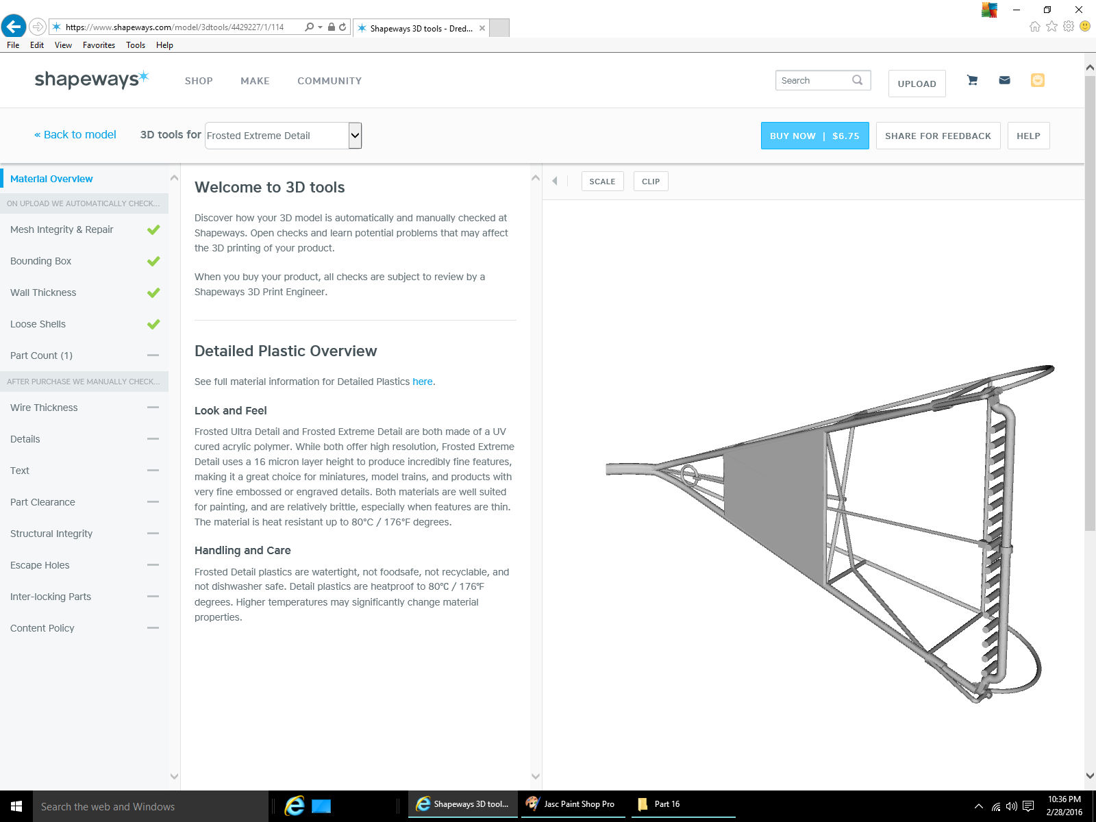
-
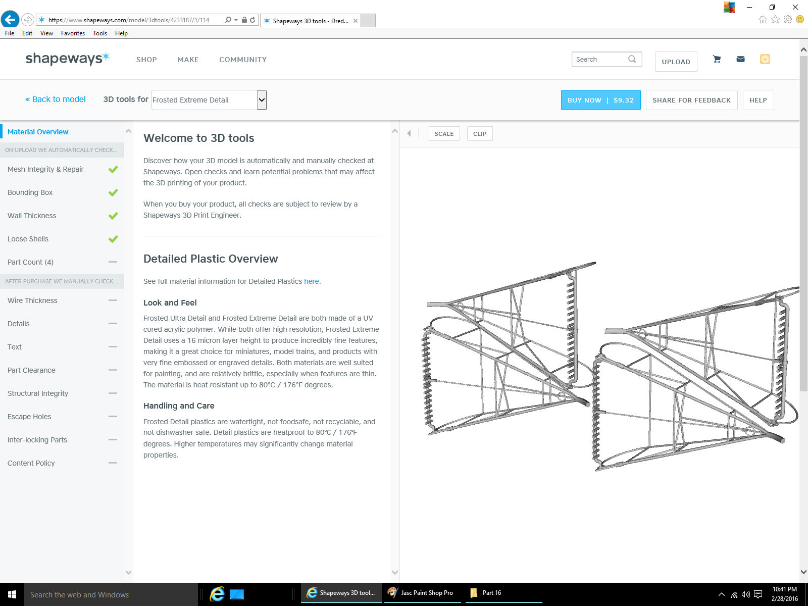
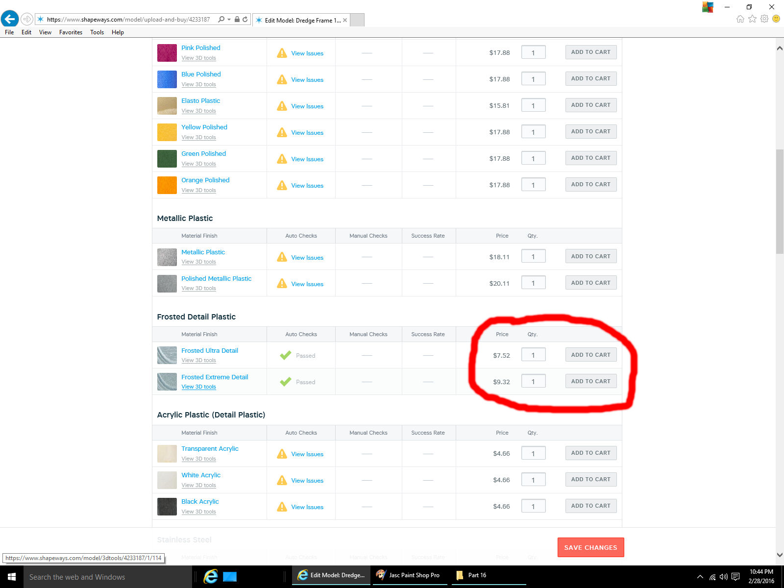
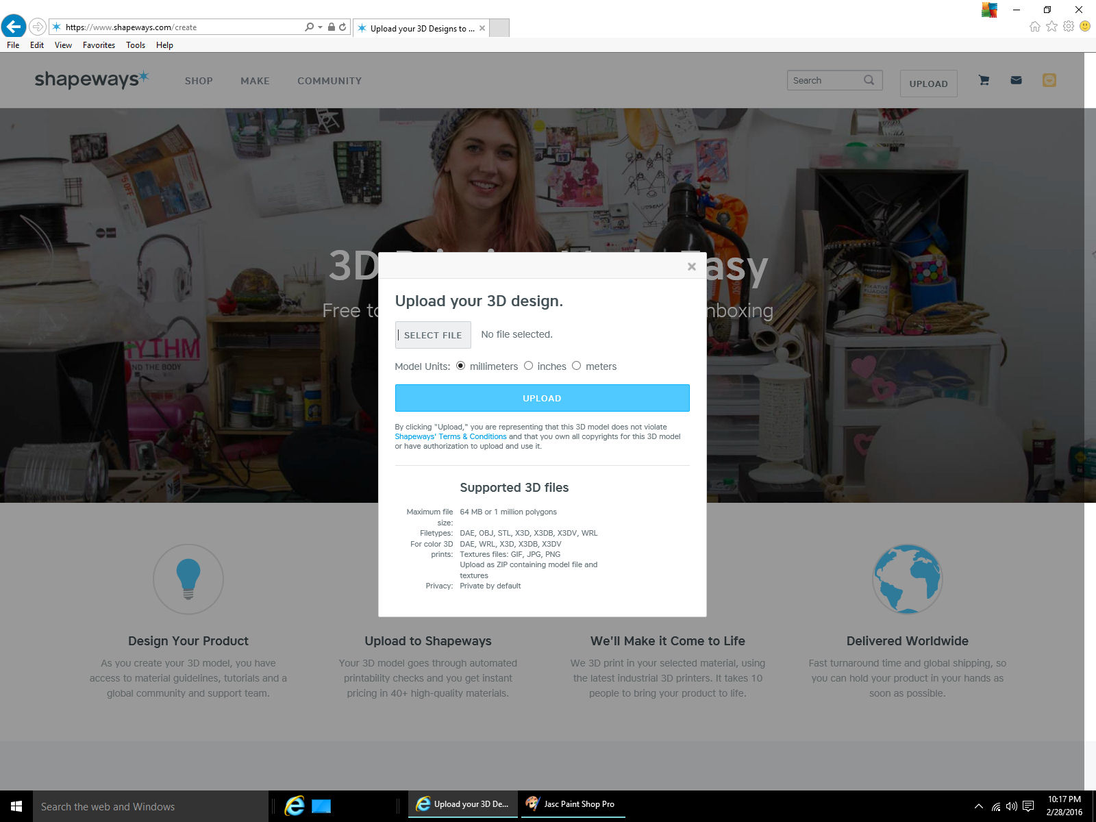
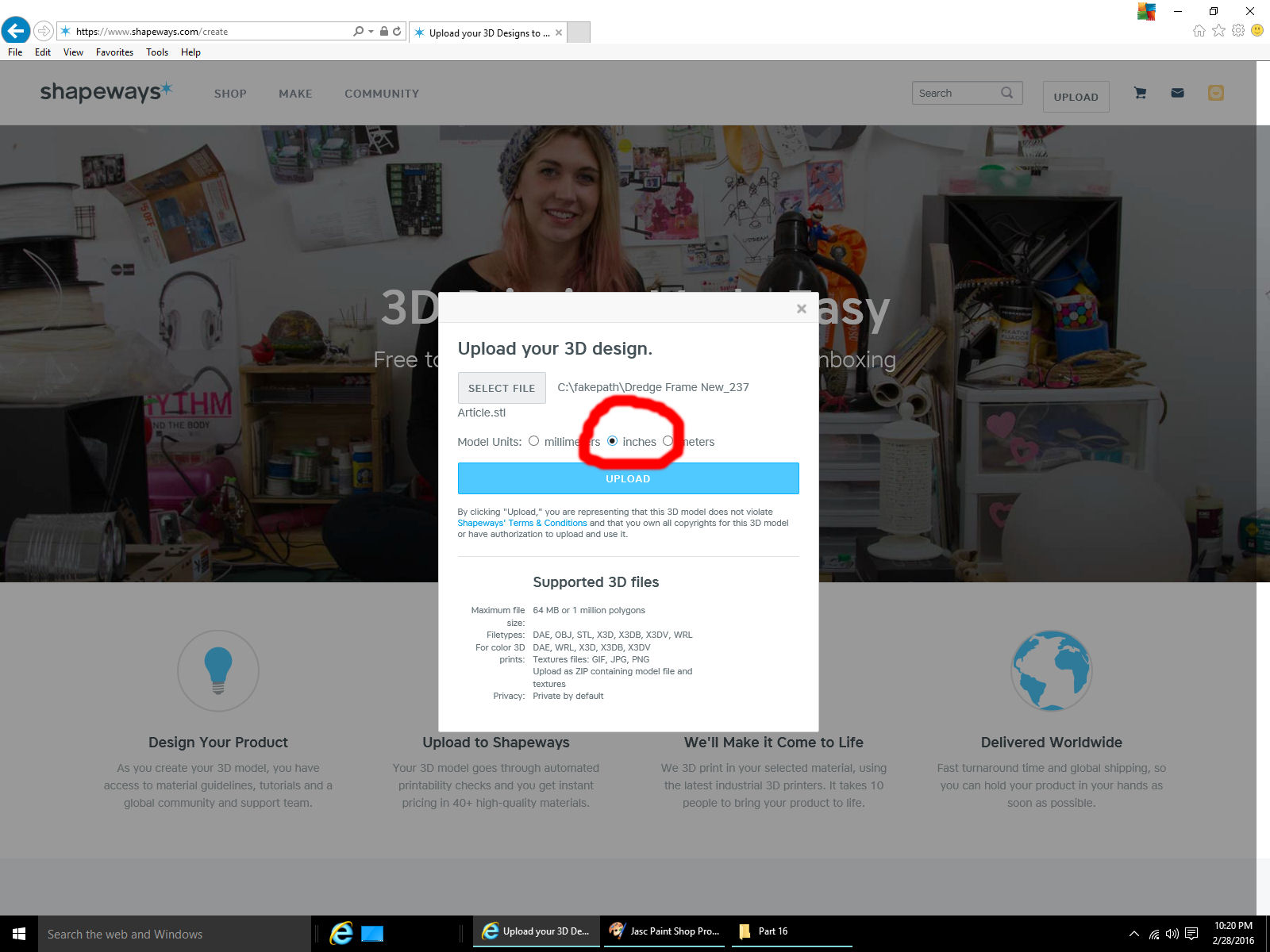
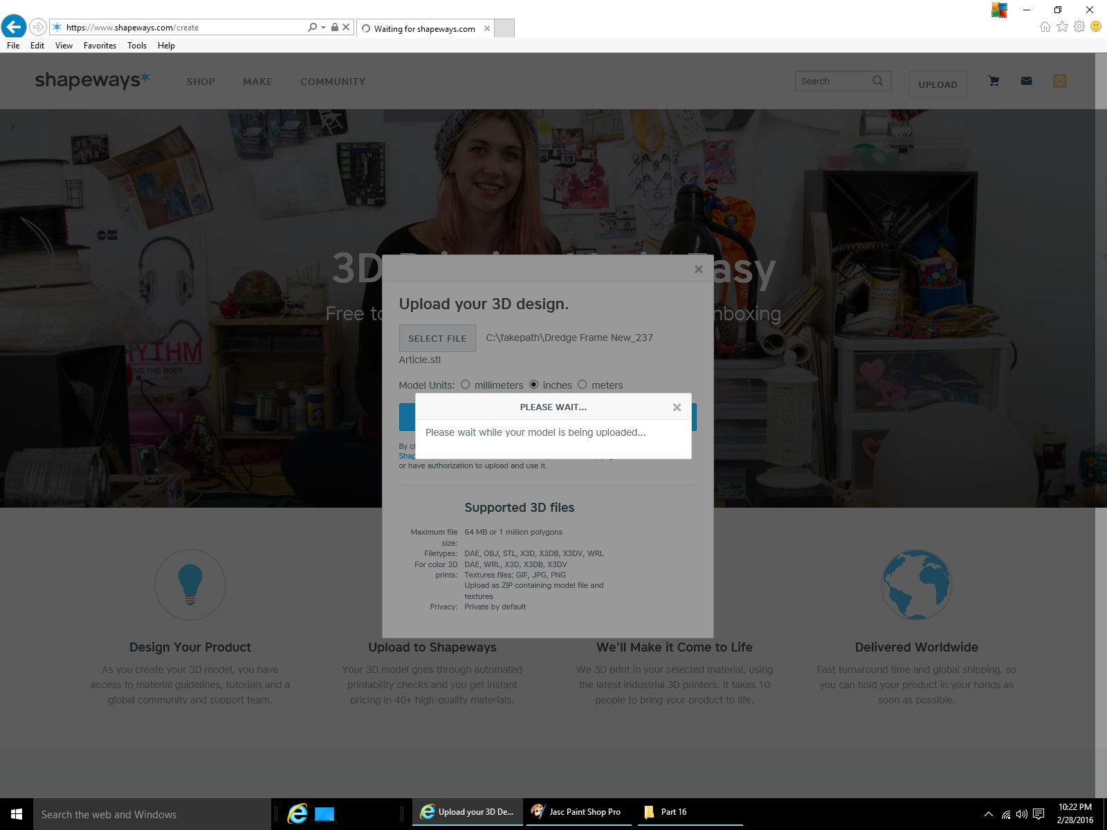
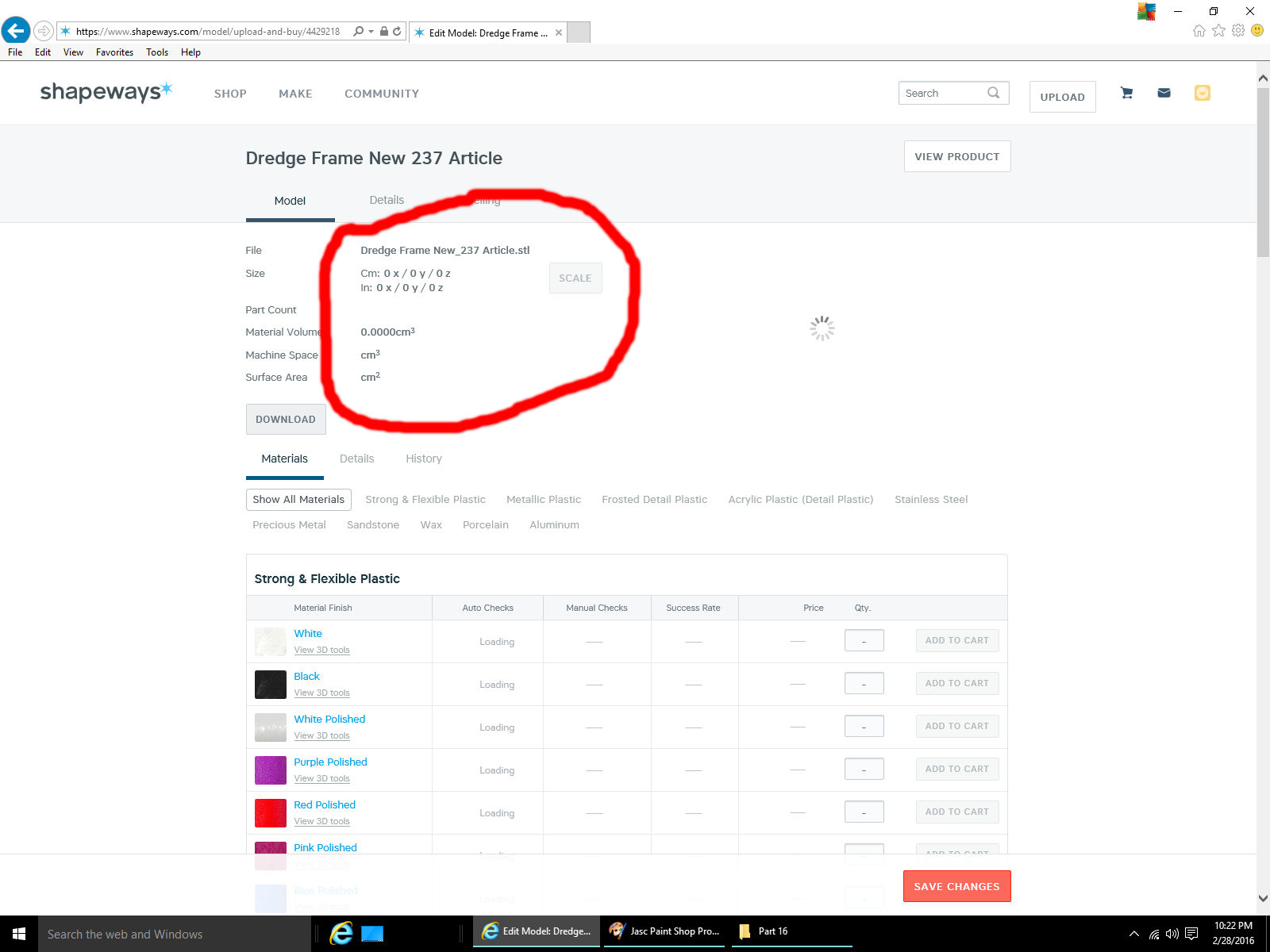
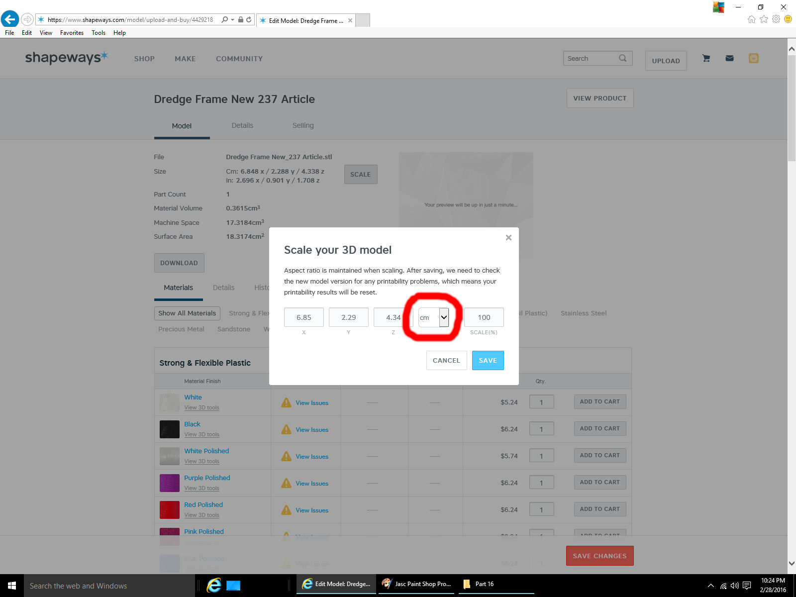
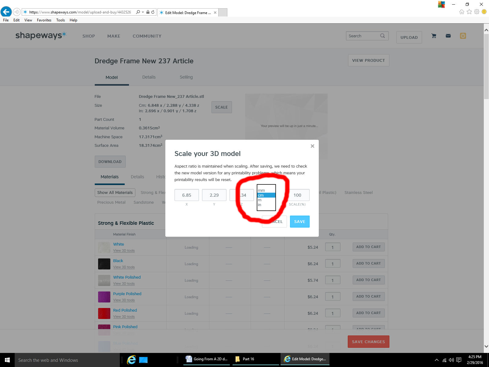
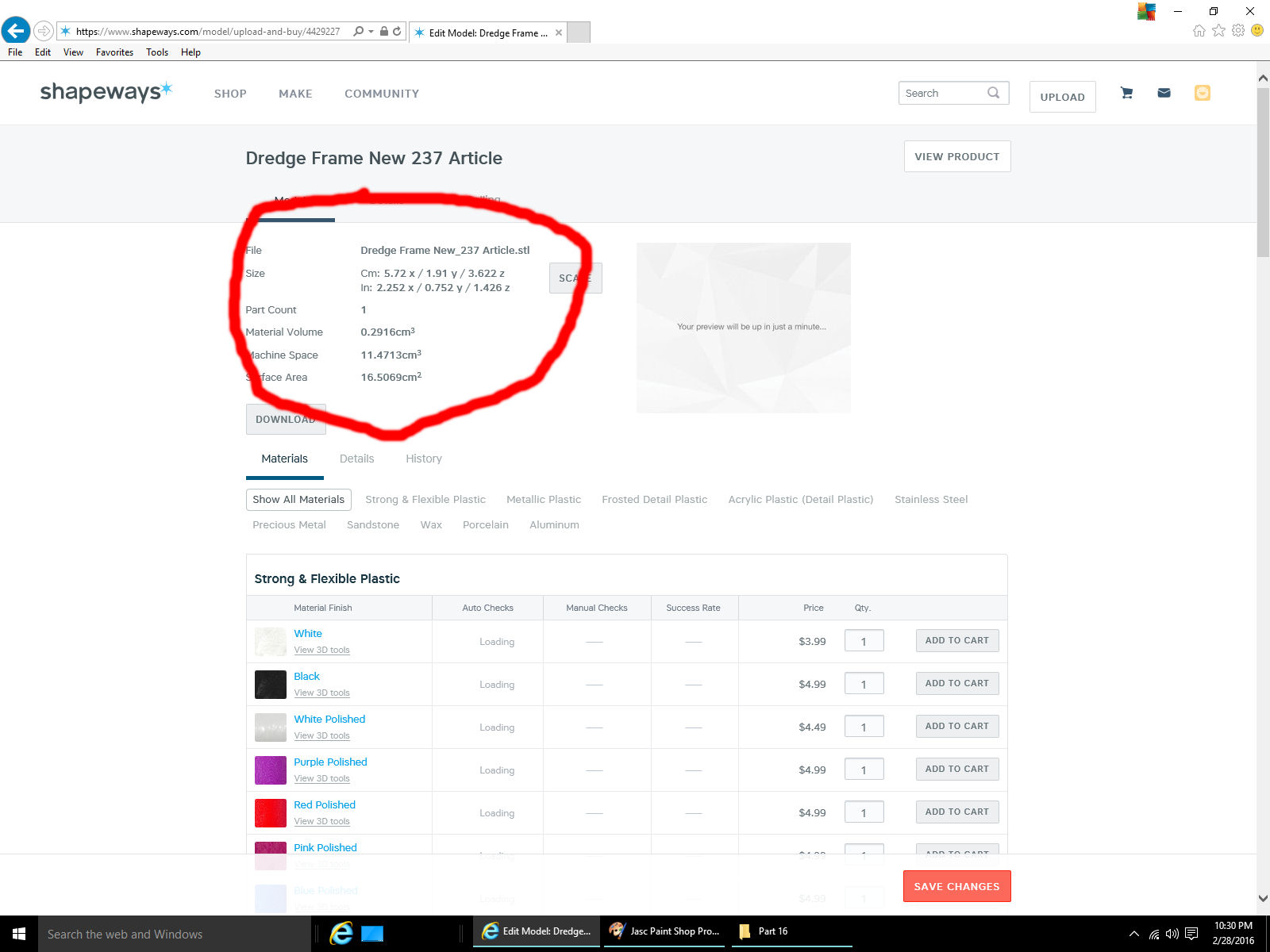
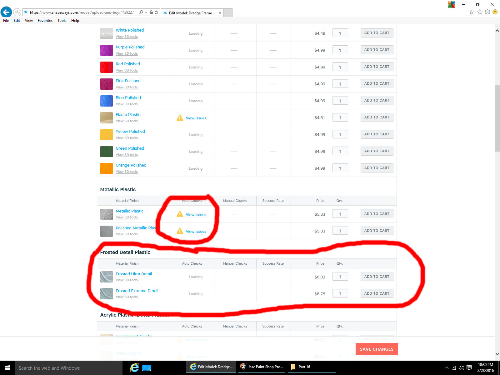
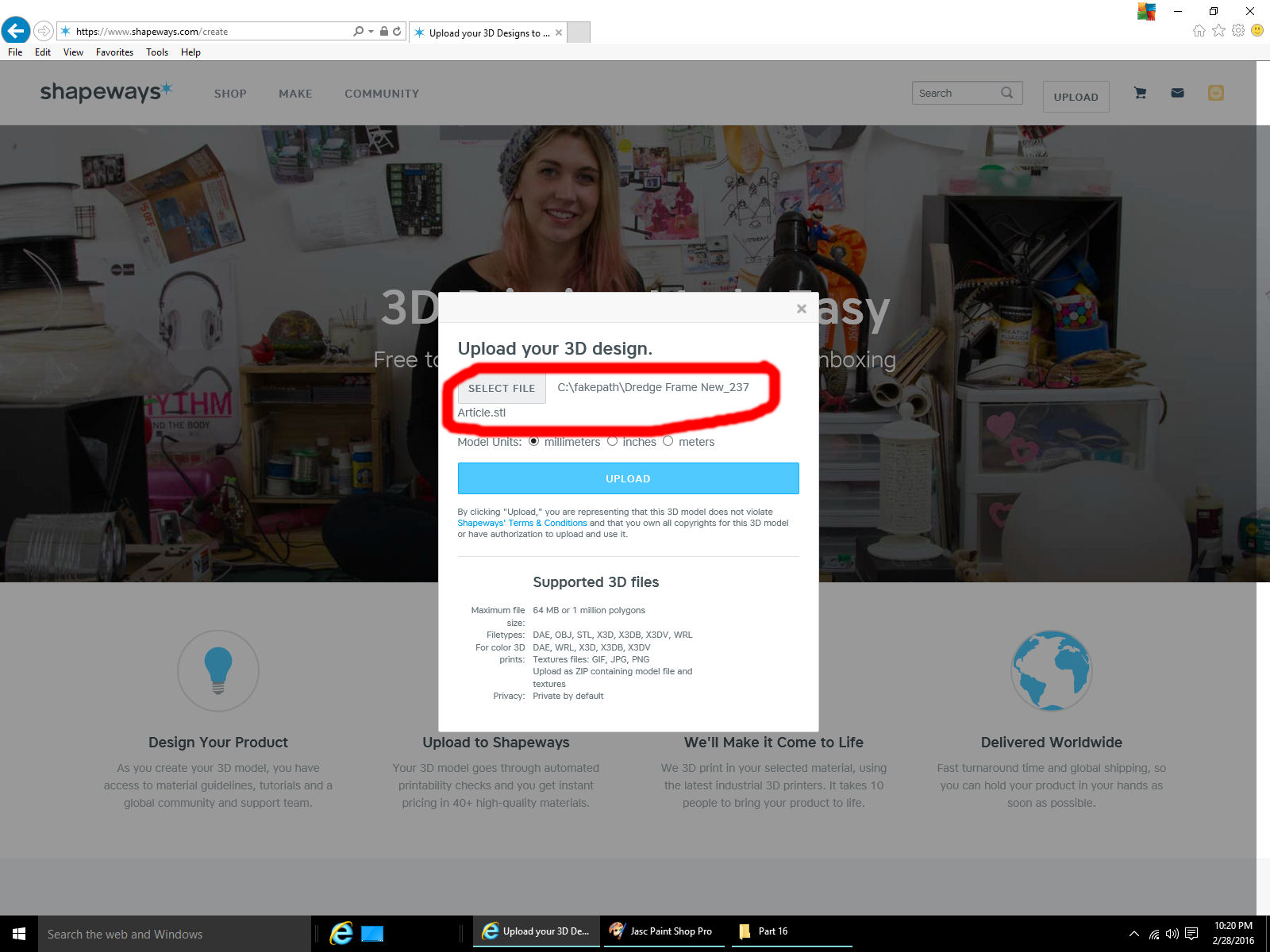
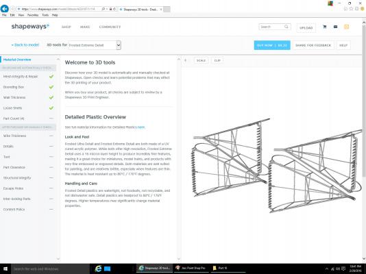
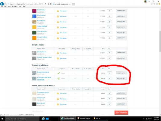
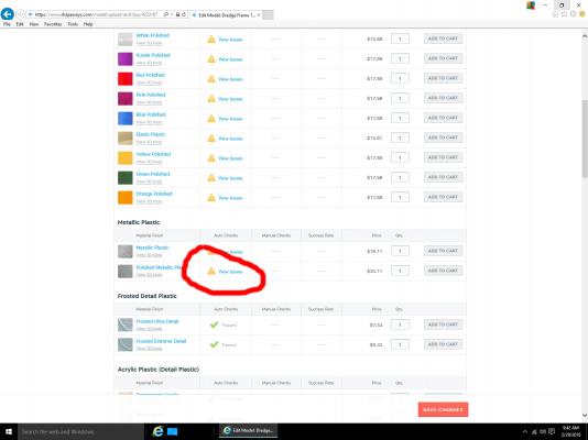
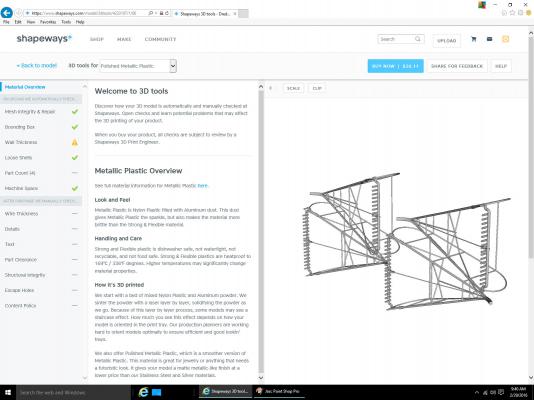
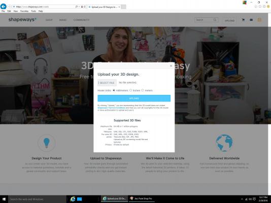
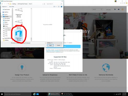
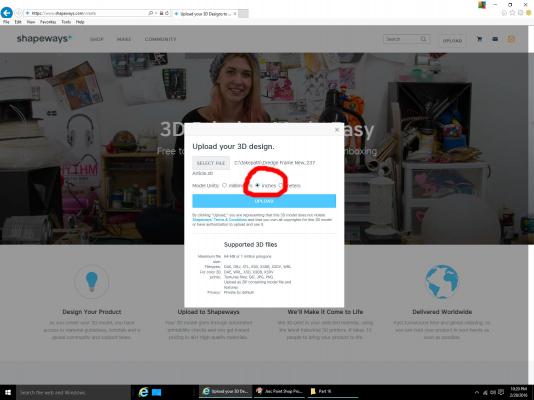
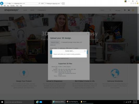
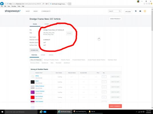
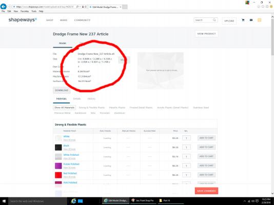
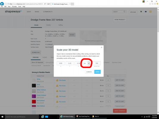
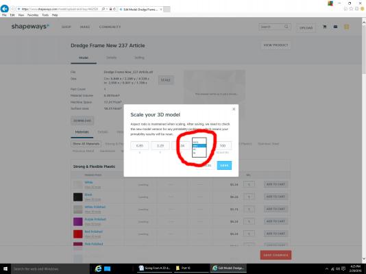
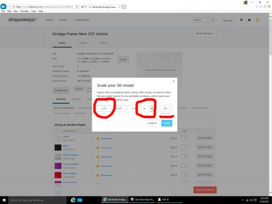
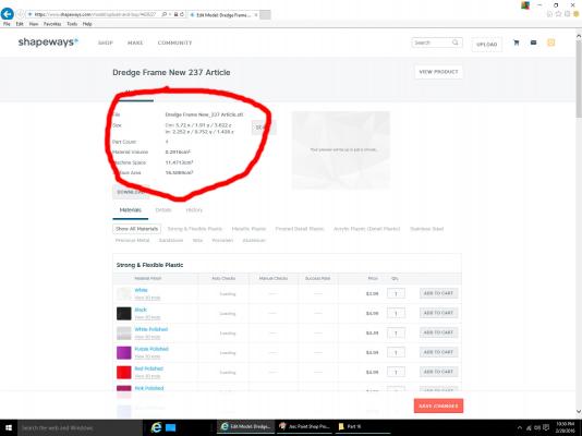
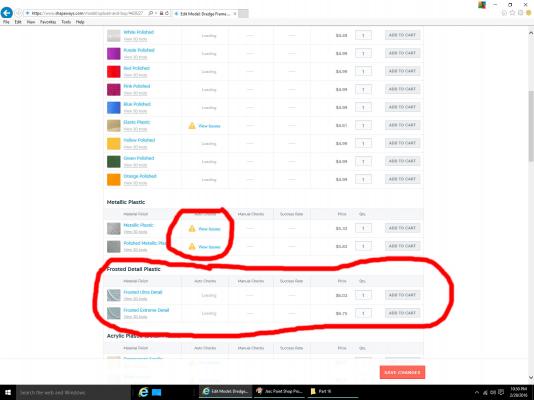
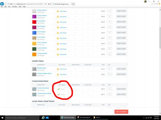
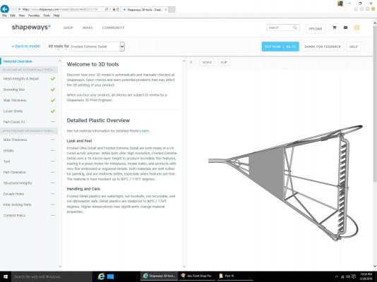
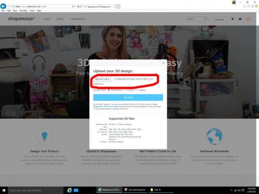
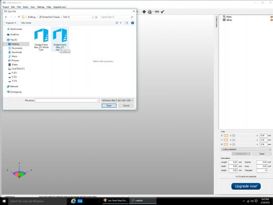
Part 16A Now we finally get to send something to the printer’s!! We have our STL file from Part 15, and this post will show the process of sending it to the printer to be checked for printability. Shapeways has a site where you can upload your drawing, have it checked for printability, be given the cost, and then order your part(s). Below is the opening screen, with the address circled. They have a page on their site where you can see what you have downloaded previously, and order more parts if you need to. Select the Upload button, and the screen to select which file you want checked will open. Select the file before you select a measurement unit, or you will not be able to select a file. Click on the SELECT FILE button, navigate to your STL file, select it and open it. The window will show what file has been selected Now you can select your unit of measure. In my case it is inches. The Shapeways printers are metric machines, and they prefer that you use metric for your model. You can use inches, without problems. When you scale the drawing, as shown later, the displayed measurement may be slightly different than the one you entered, due to the internal conversion to metric, but it will be undetectable in the finished model. Generally the difference is in the hundredths to thousandths of an inch. If it is more than this, rescale the part, or restart the download process. Select the UPLOAD button, and your file will be placed into the system. First a screen showing you that the file is being loaded will pop up. After the file is loaded the software will display the scaling screen with the values at zero. After some time, depending on your file size, or how busy they are, the window will display a scaled value. I assume that they roughly scale it to fit in their printer volume. As the given measurements are unlikely to match what you want, you need to rescale the part. Give it a few moments after the initial scale is displayed before you go to the rescaling screen. If you click too soon, you will generate an error. If this happens exit the window and try again. Sometimes I’ve had to restart the whole process. Select the SCALE button. The window below will be displayed. Notice that the unit’s defaults to CM, if you are using another type, select that first, then enter your scale measurement. The available units are shown below. I am using inches. Almost all my models will be based on US ships, or older European ones, before metrification, so I will probably always use inches. Now enter the scaled value for one of the dimensions. In this case, and generally, I’m going to use the X axis length. You can use any axis that will scale well. In 1/32nd scale the dredge frame comes out to about 2.25 inches long. For this post I did not take the time to calculate a more precise measurement. The other axis measurements will automatically be rescaled, and the scale factor will be displayed. Select the SAVE button, and the first screen will be displayed again, and after some more time, the new dimensions will be shown. As I stated earlier, the disadvantage of using inches, is that some small difference between what you entered, and the new measurement may occur. In this case I get 2.252 inches. Unless you are making parts for a nuclear reactor, it makes no noticeable difference in the finished part. The columns below the scale display show the various materials you can print your model in, whether your model is acceptable in that material, and the cost to print it. Shipping is extra, but if you submit several files at the same time, they will combine shipping. For our parts we will almost always need to use the materials that print the finest, the Frosted Ultra and Extreme detail plastics. I’m not sure what the detail definition difference is between the materials, but I use the Extreme, which has the finest detail. The cost difference is minimal, so I have not tried the Ultra Detail material. The picture below shows the screen of the progress to the checking. The Auto Checks column will say Loading until the checks for that material are finished. The checking for the Frosted Detail material generally takes the longest. The picture shows that the software has already determined that there are problems with printing it using the Metallic Plastic material. You can also see how much it will cost to print in each material, assuming that it passes the requirements. When the checks for each material are completed, a Passed, or View Issues result will be shown. For the dredge frame, either Frosted Plastic material can be printed. If you select View 3D Tools, a window showing the detailed results is displayed. For these parts, everything checks out, but you need to look further at the Wall Thickness requirement. There can be hidden problems, that while allowing it to be printed, might have to be corrected for a good detailed part.
-
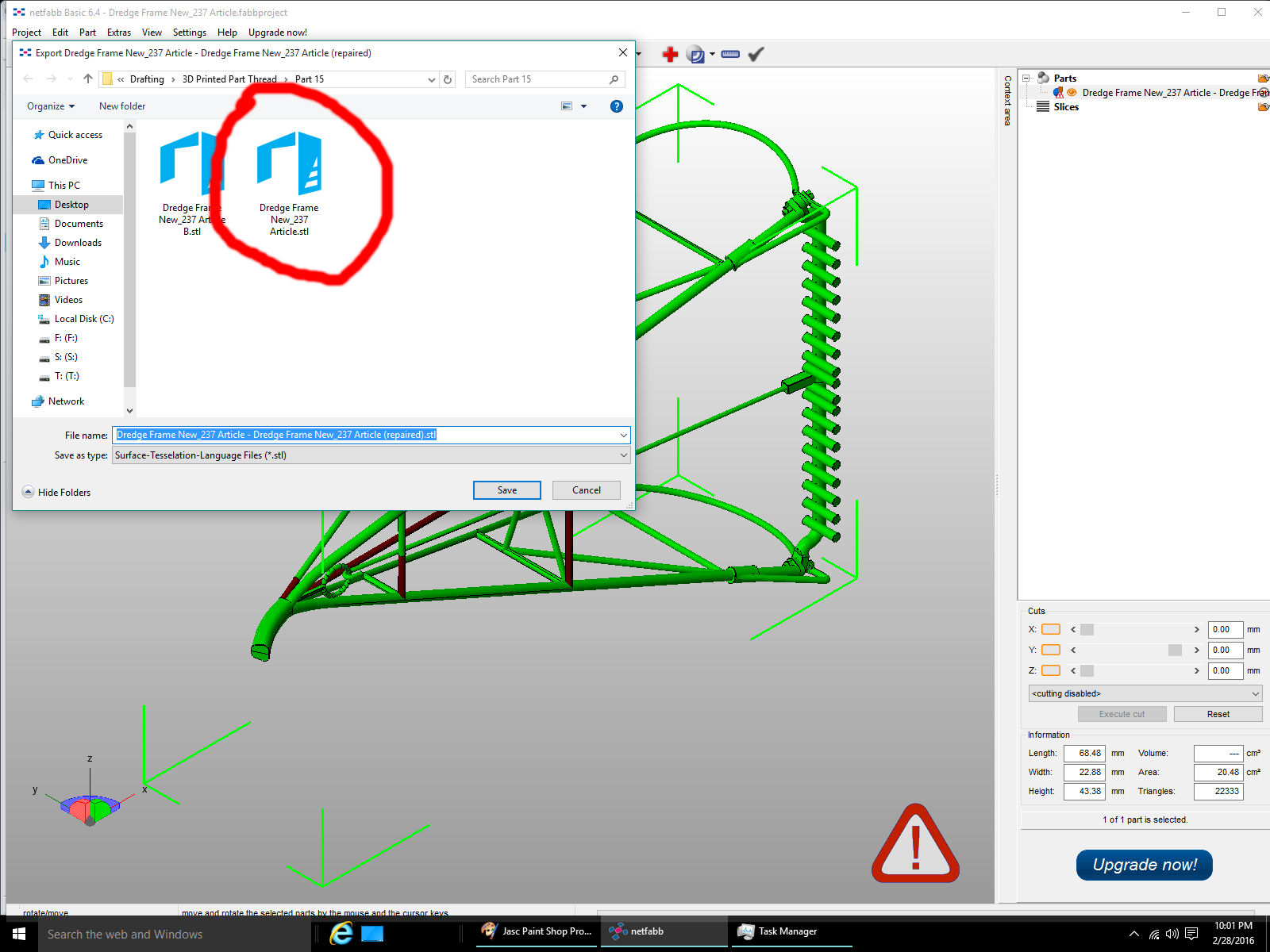
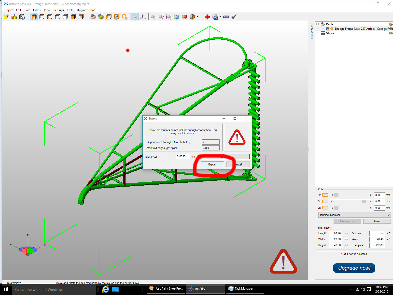
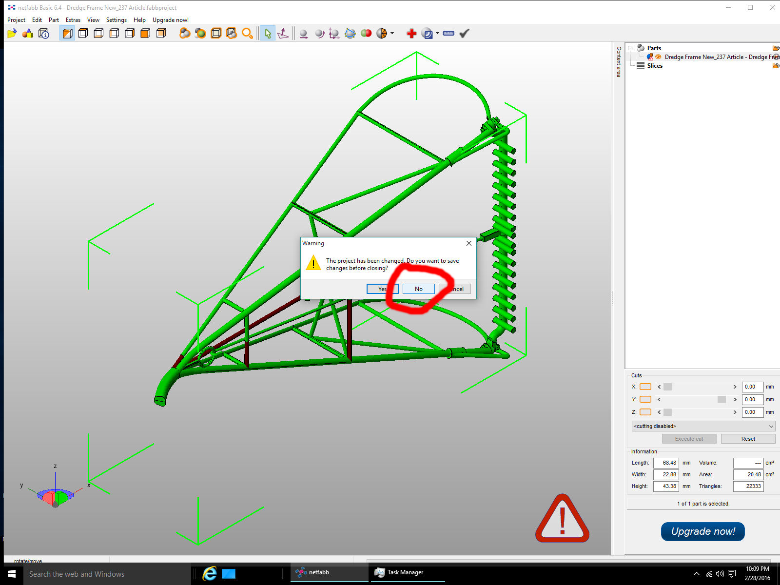
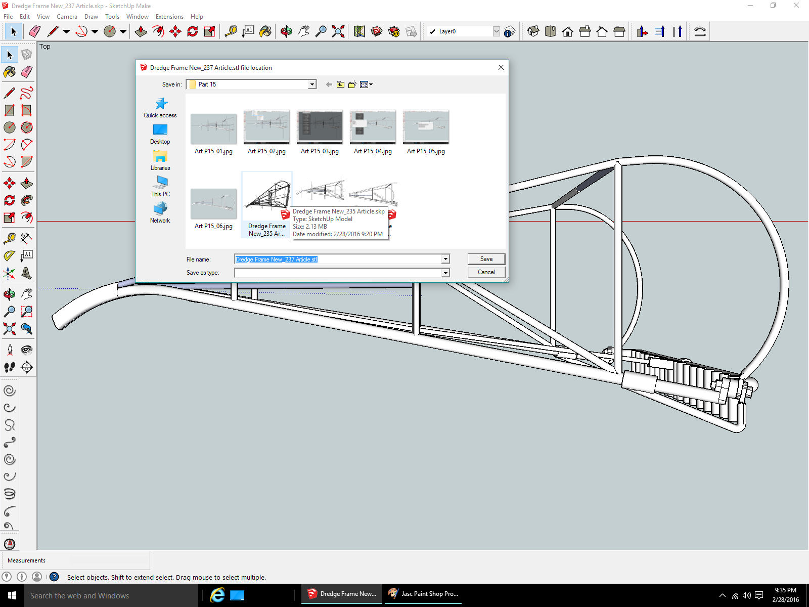
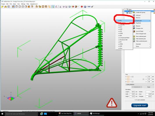
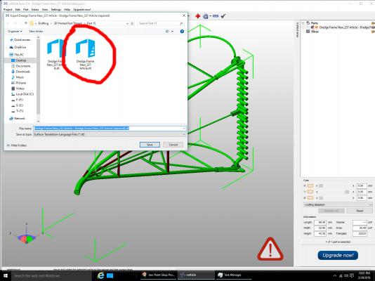
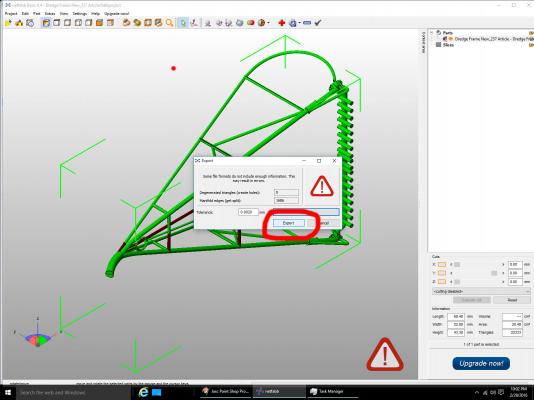
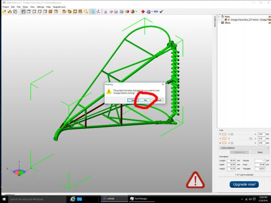
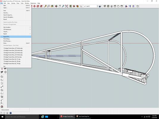
Part 15C Now we have to save the part to an STL file, the program converted it to its native format when it was opened. Select the file in the right hand window, then right click on it. The menu below will open, select Export, then as STL. Select the menu item. The window below will open. Notice that the program used the same file name as originally opened, for the first part of the new file name, then it added its “(repaired)” text at the end. Rename, if desired, then select Save. The window below will be displayed, select Export. You can now close the program. Select No for saving the drawing as a netfabb project. The next post will be the process of importing the STL file to the Shapeways site, and checking it for errors that might affect or prevent printing of your part.

-
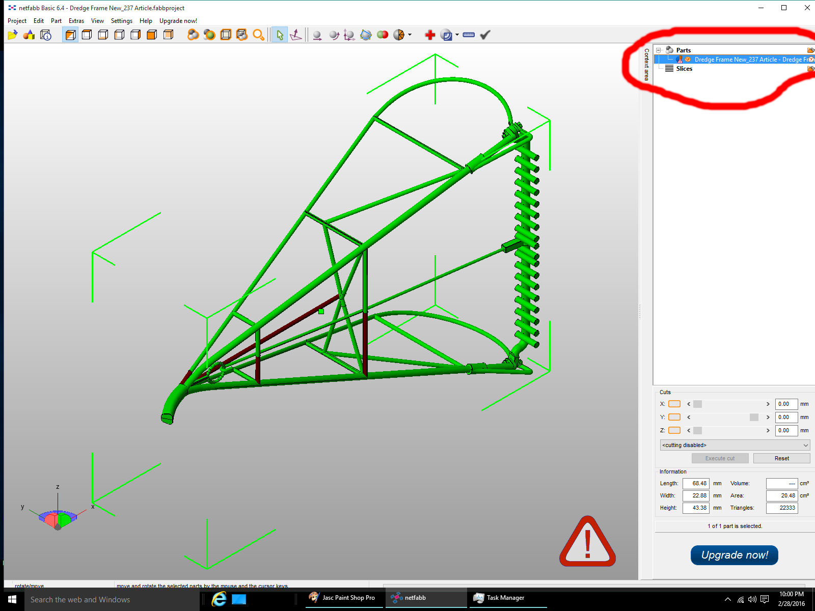
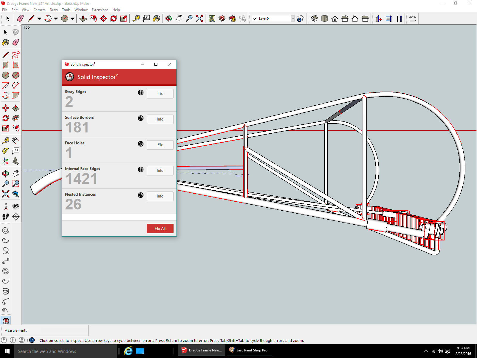
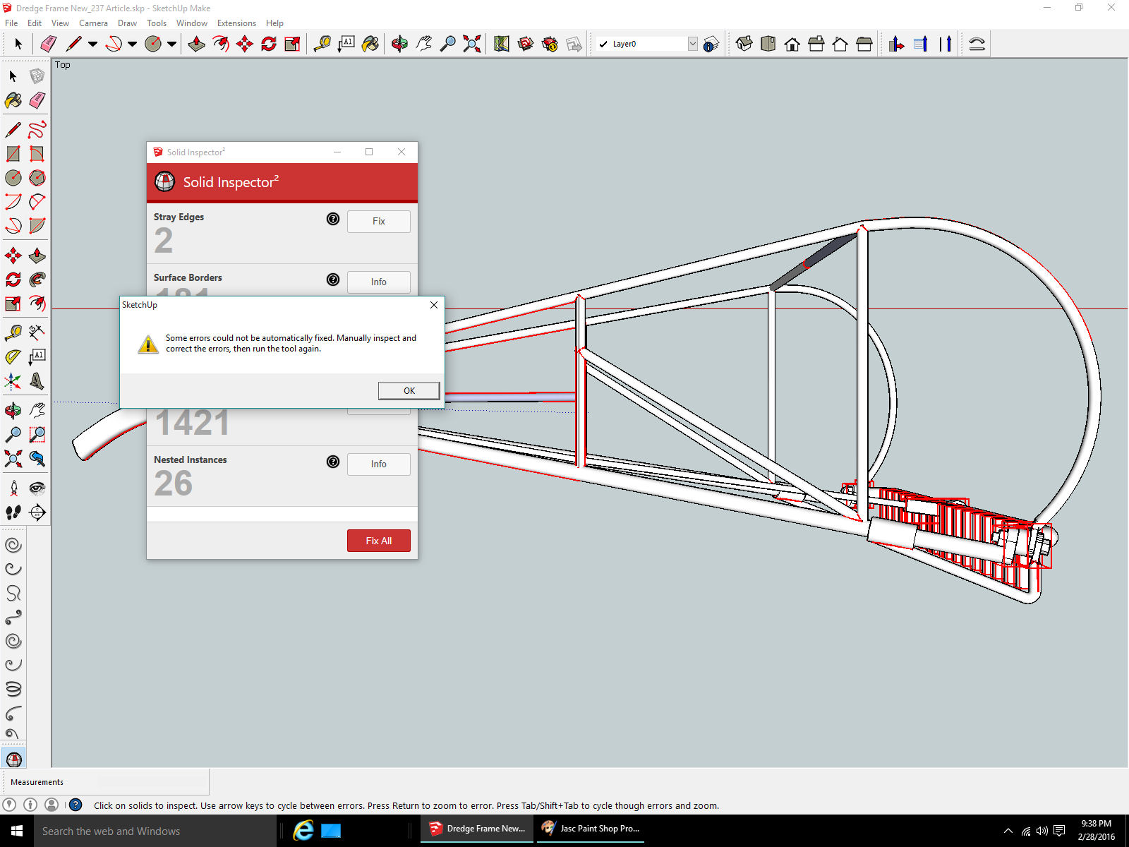
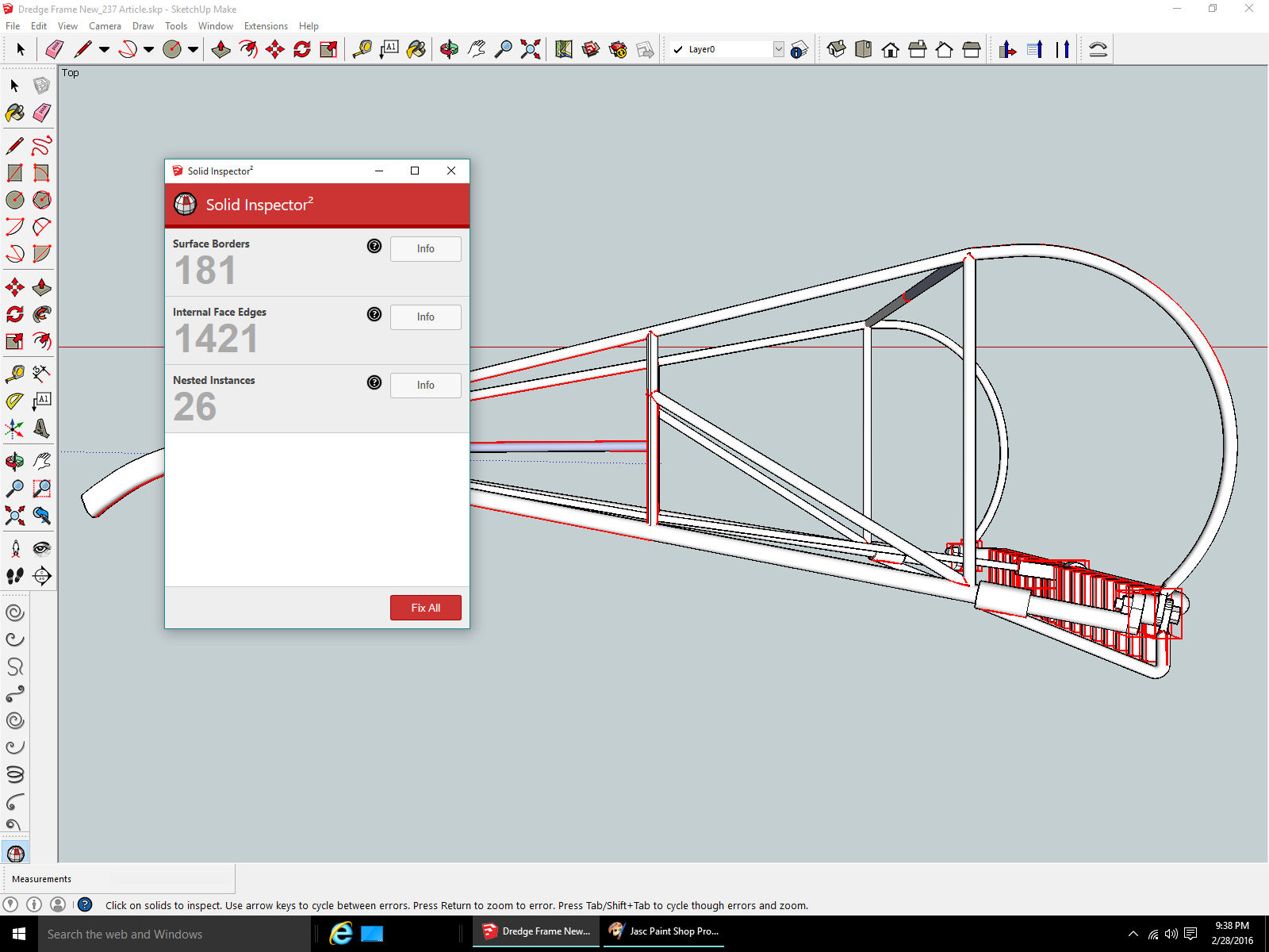
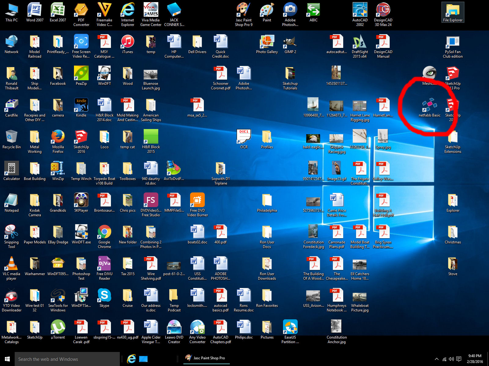
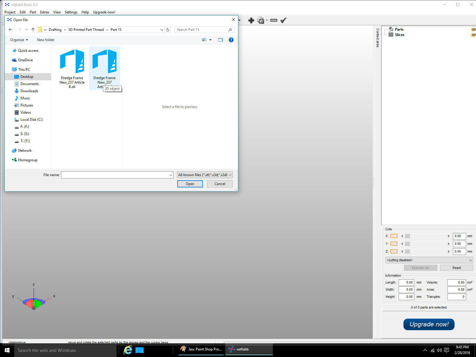
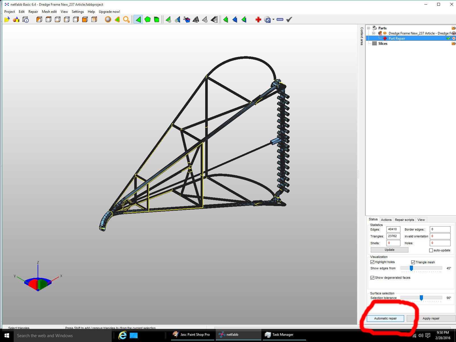
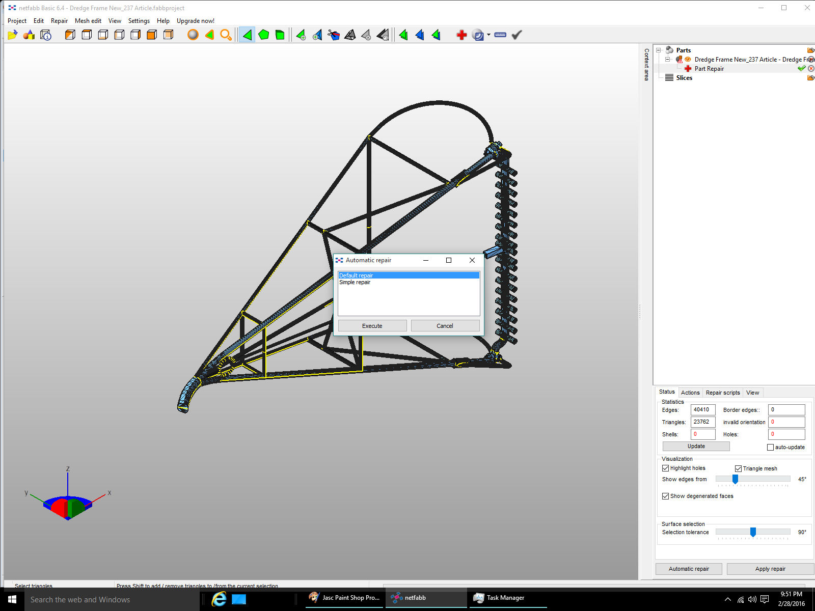
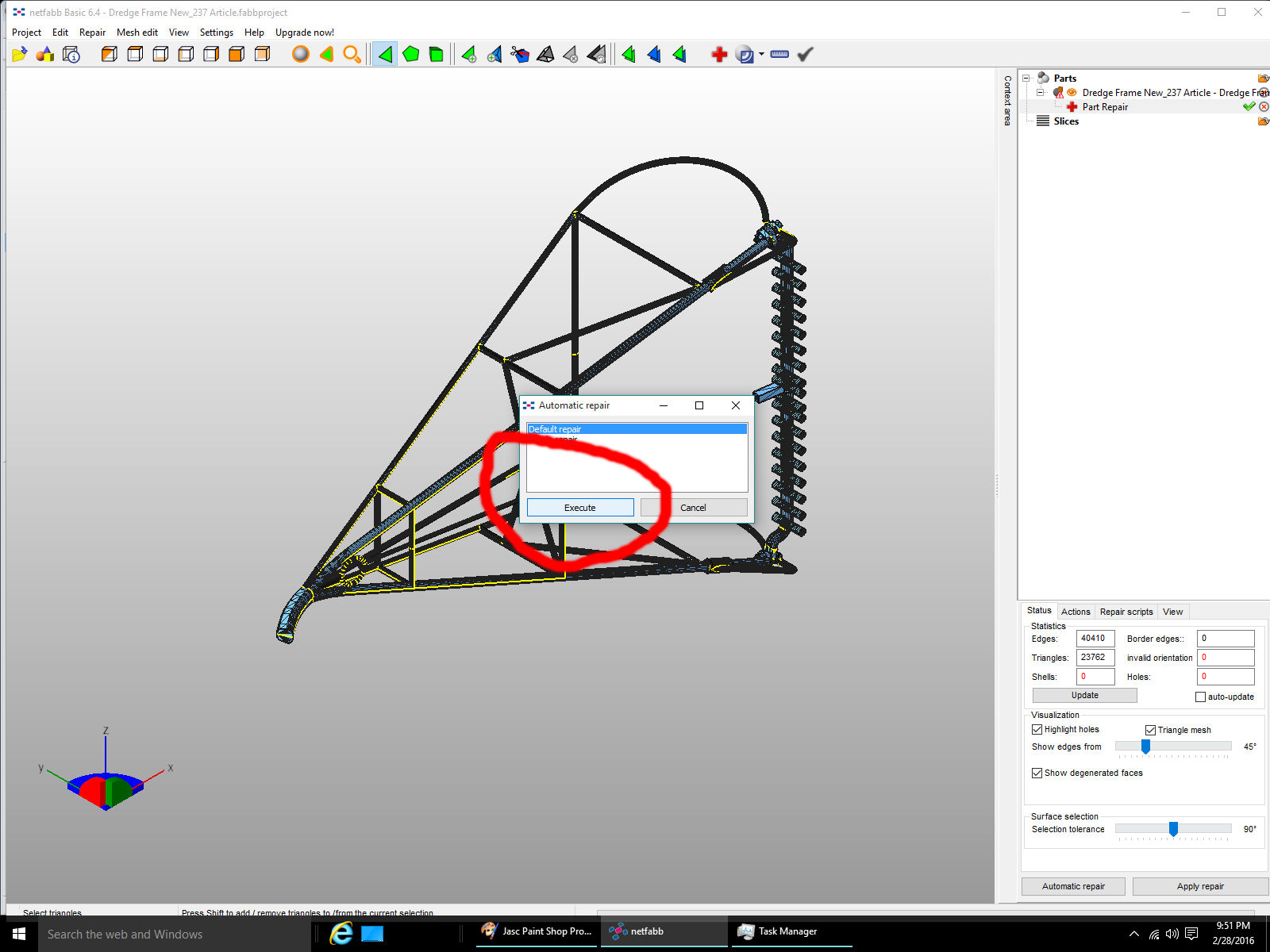
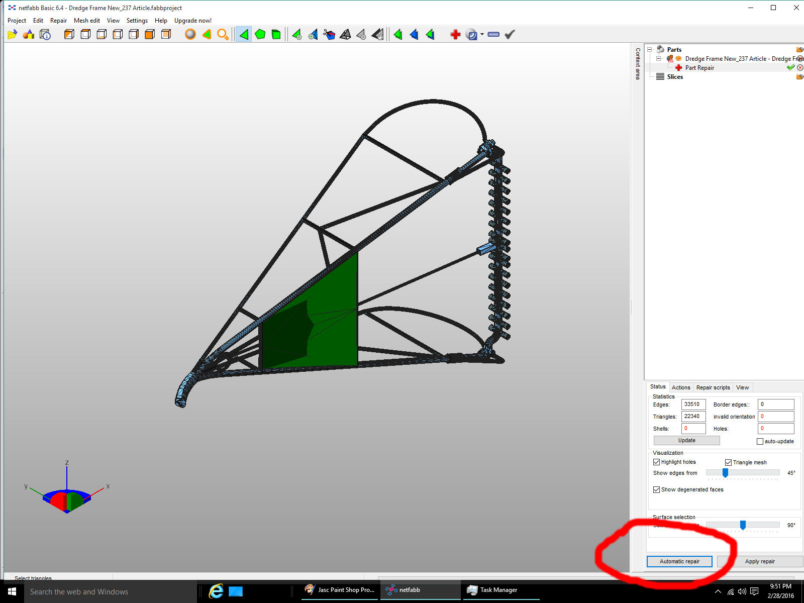
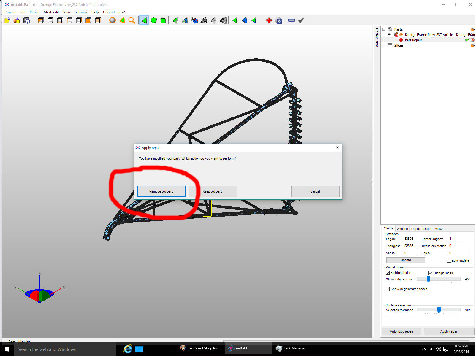
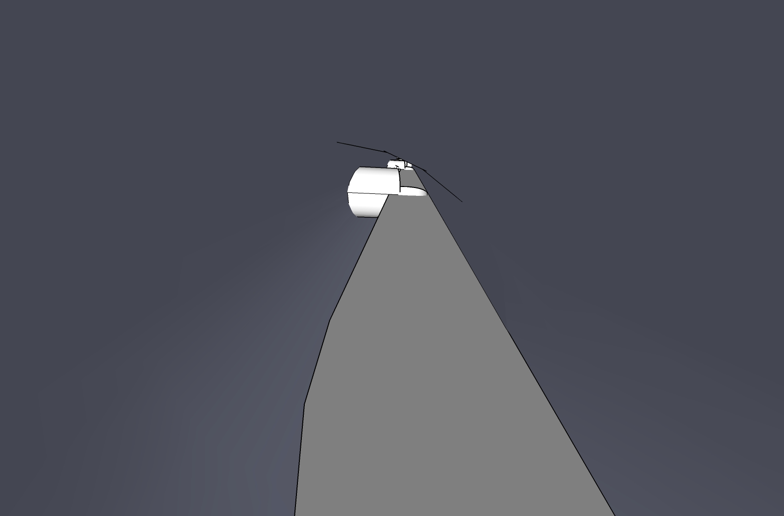
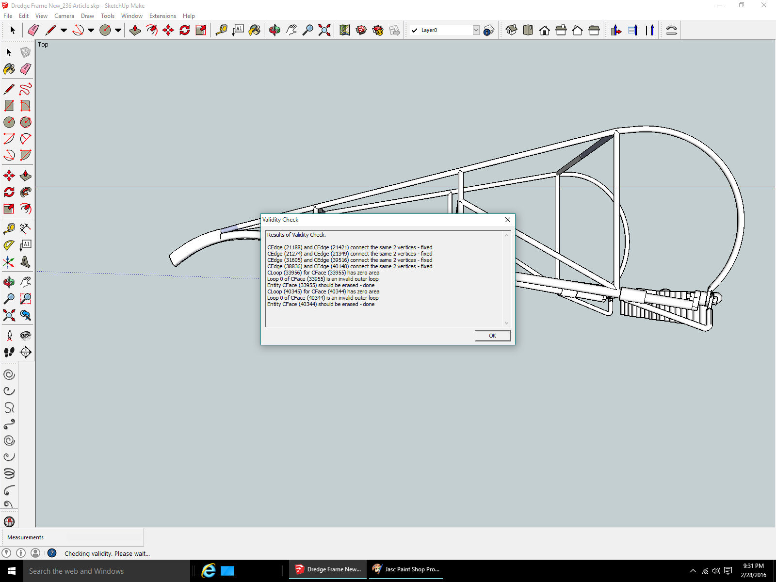
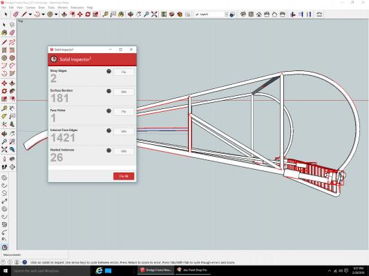
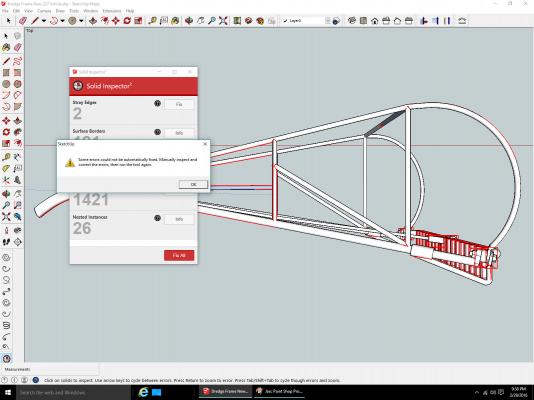
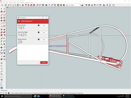
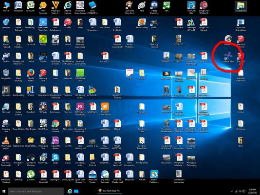
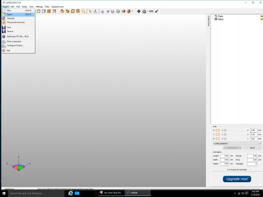
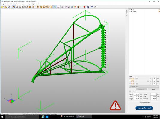
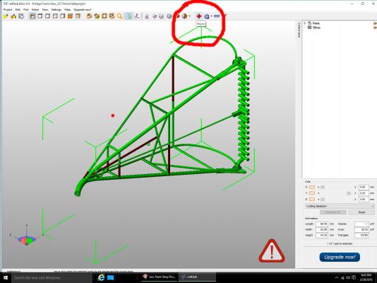
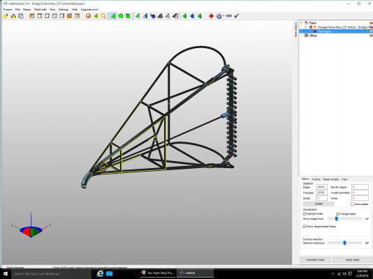
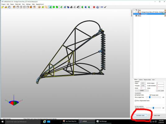
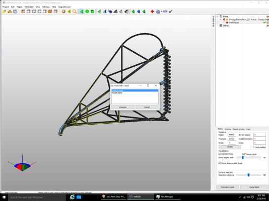
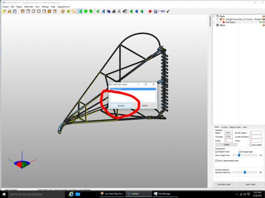
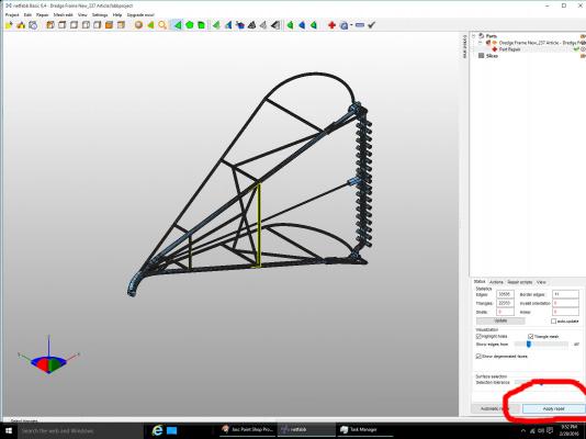
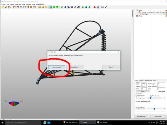
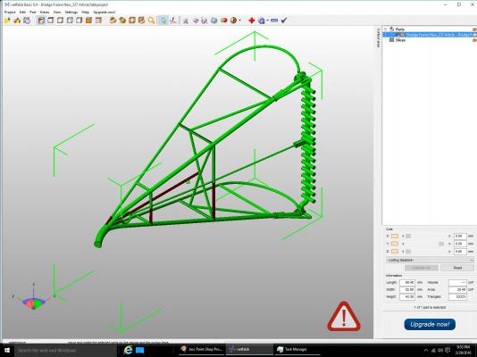
Part 15B The first check is the Solid Inspector2 (be sure to used the 2 version). When this operation is started the screen showing the problems found will be displayed. Select Fix All. It will tell you that it could not repair all the problems, Select OK and continue. The fixes that the operation can do will be done, and a window showing the remaining “problems” will be displayed. Most times these remaining problems will have no effect on your final part, and can be ignored. Be aware that the correction may involve erasing areas of your part, so check carefully after this step. This is why I save an STL file before and after this and the next netfabb steps. Save an STL file after this operation. The final check will be done with a free program called netfabb Basic. It has many operations it can do, but I have only used it for the checking/repair operation. Start the program, then select Open from the File menu. Here I selected the STL file from the uncorrected drawing. OK areas are displayed in green. Any gross problems will be shown in a different color. The brown areas shown here are from the sections of the original drawing that were shown in light blue. These indicate surfaces that are reversed from the normal white exterior surfaces. They are “inside” surfaces, the back of the white surface. This normally does not hurt the drawing, but you might have to correct these in the original drawing. Select the Repair function, the red cross in the menu bar. The program will display the part with problem areas shown in yellow. Select Automatic Repair. The Default Repair should be highlighted, if not, select it, then Execute. The program added a sheet between the frame parts that is not desired! This is due to interior walls as discussed in a prior post. As I said at the beginning, this is an earlier drawing than the final one. For this example I manually erased this plain. Now the correction has to be applied. Select Apply Repair, then Remove old part. Shown is the corrected part. As with the Solid Inspector, this program might delete portions of your drawing.

-
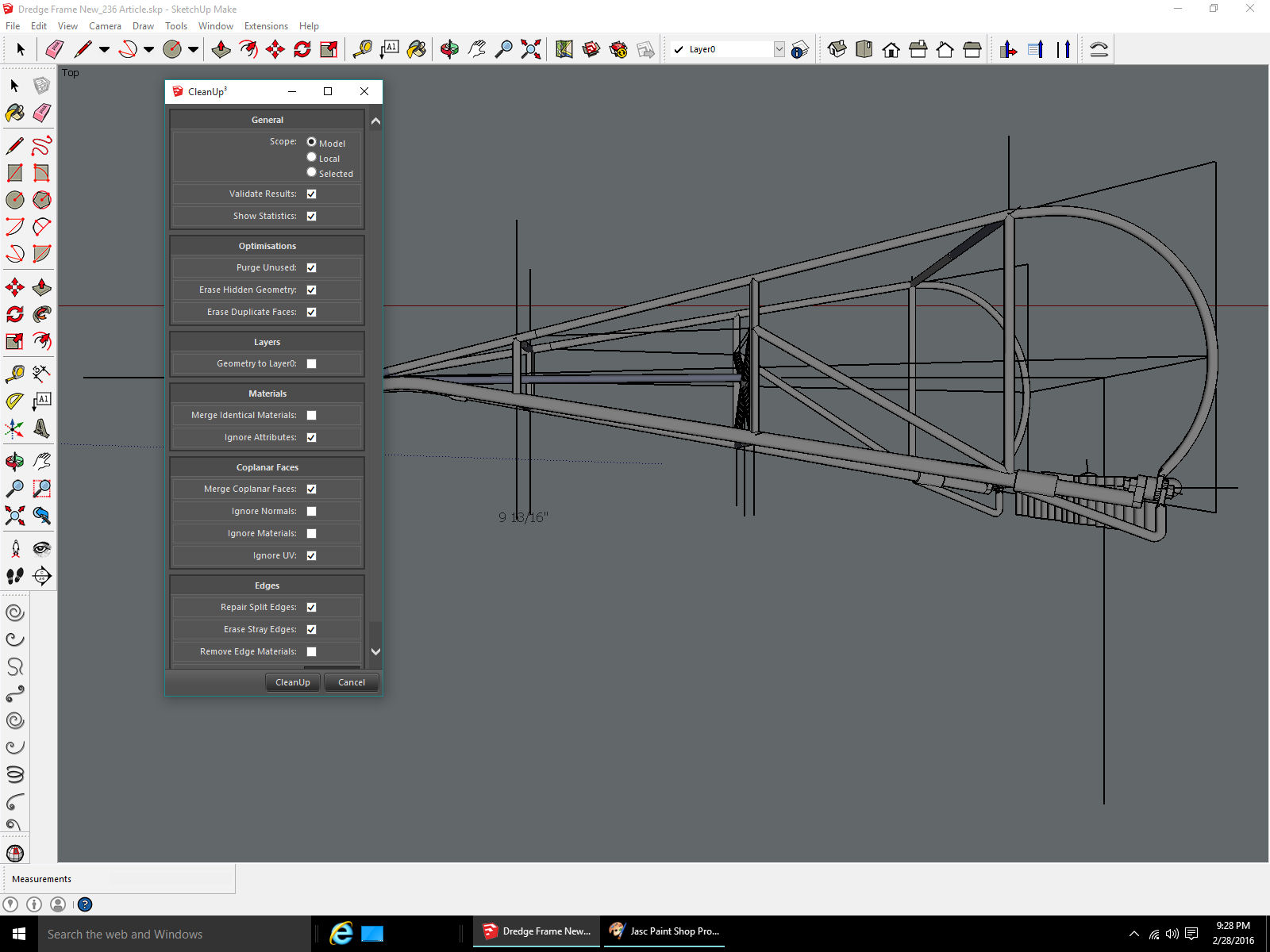
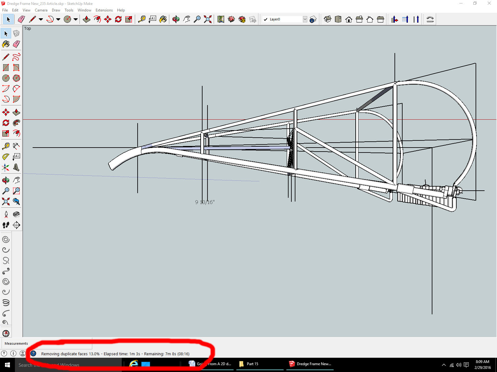
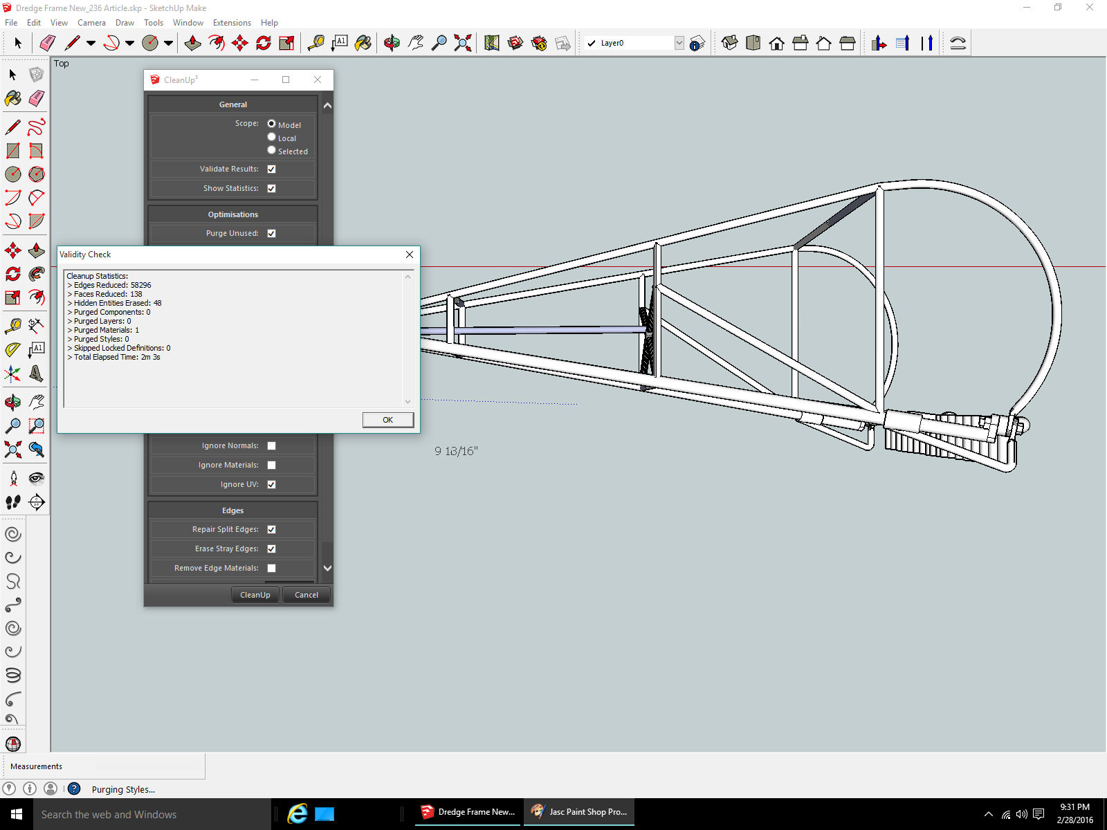
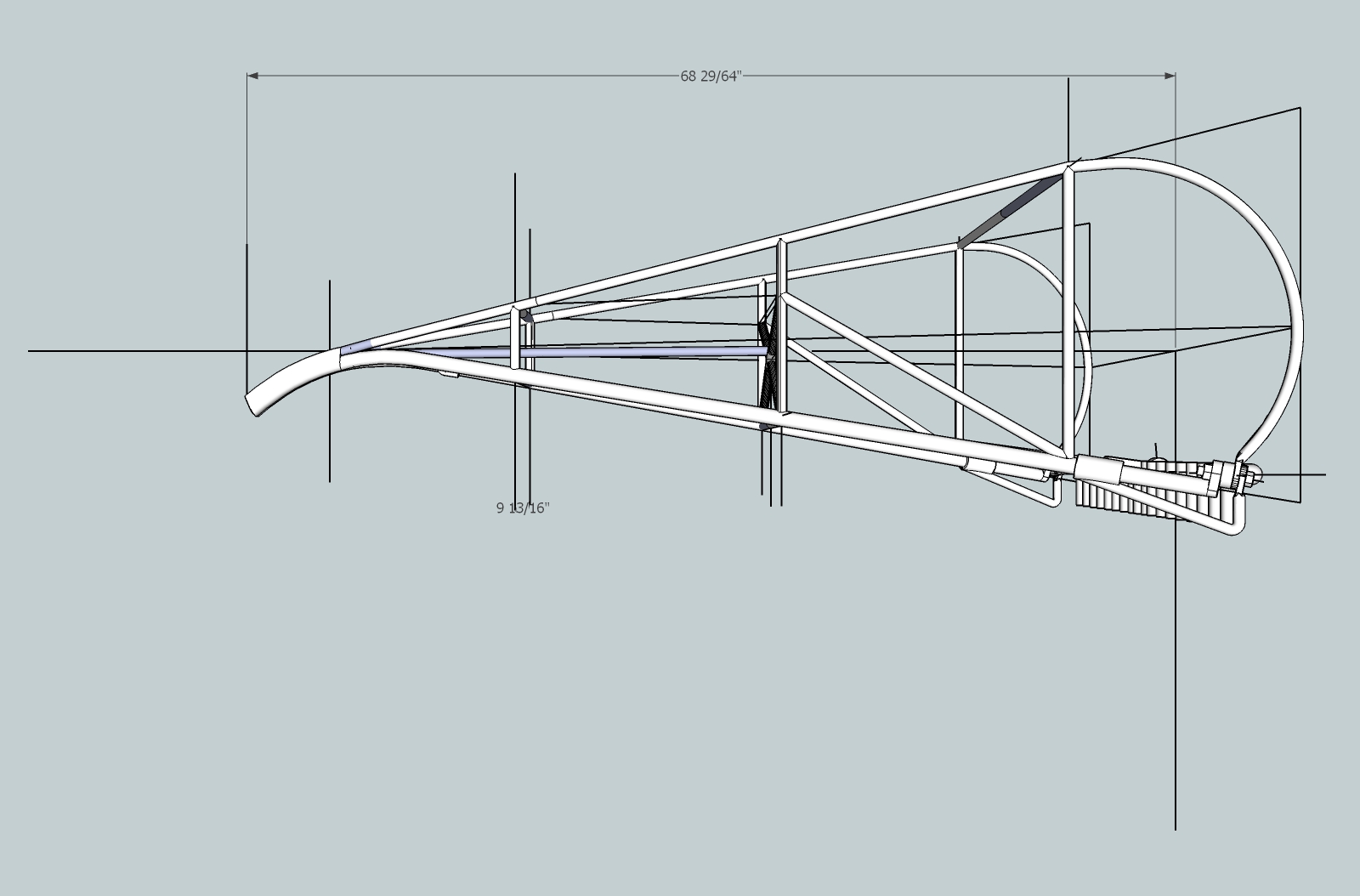
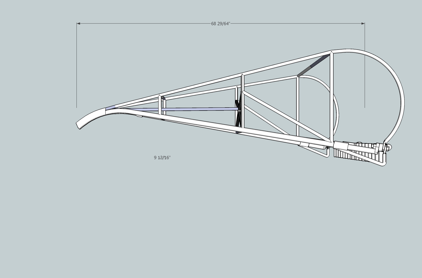
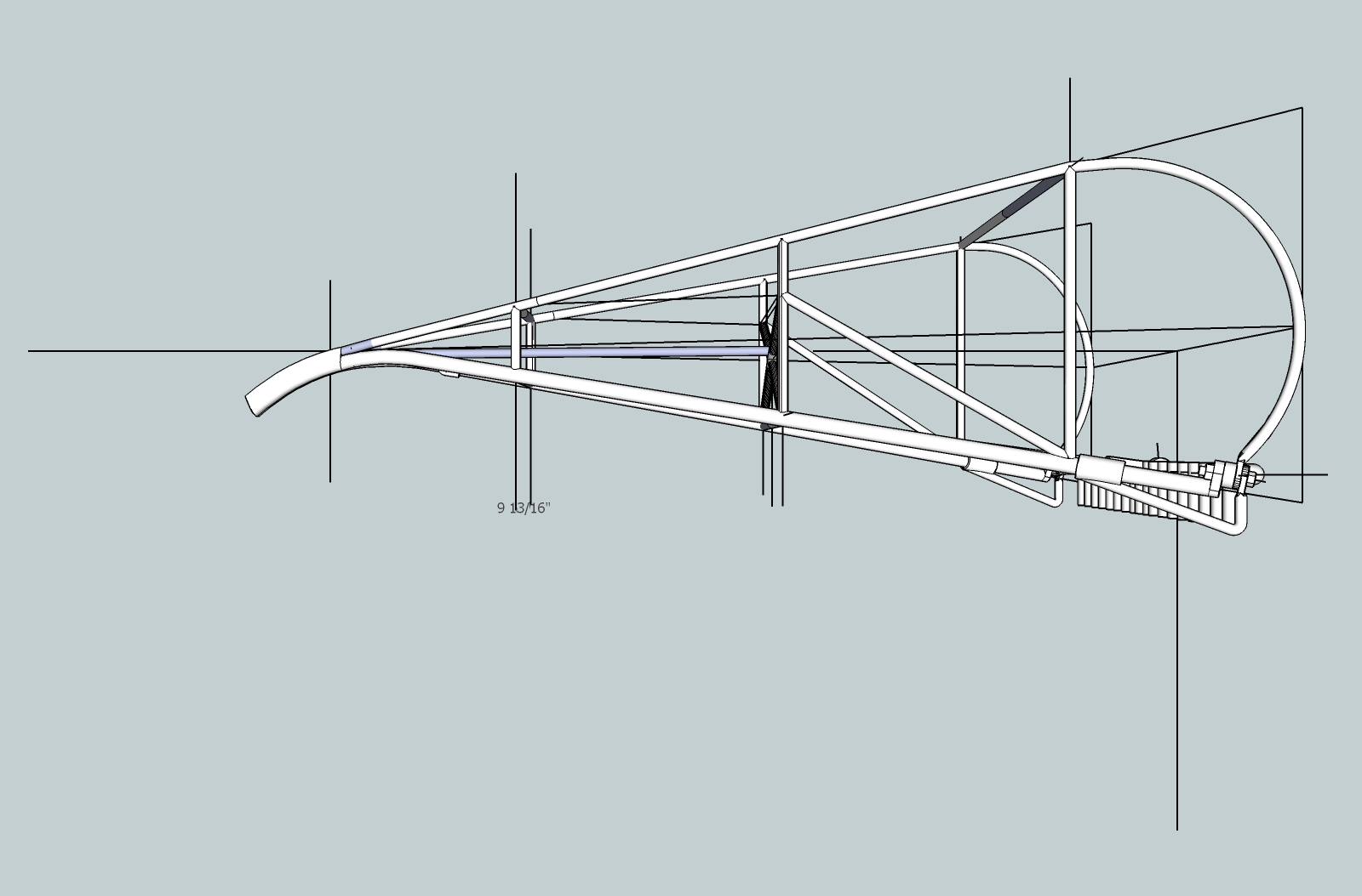
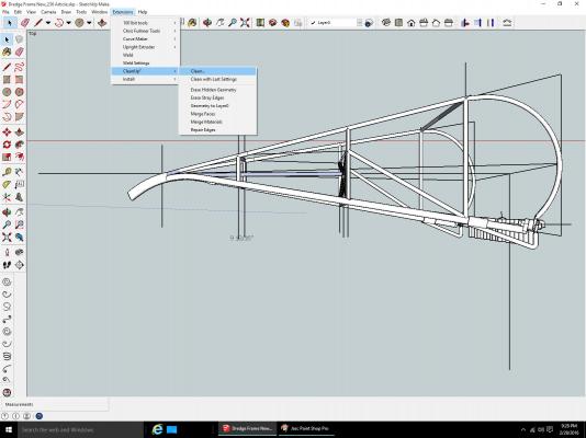
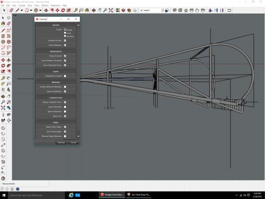
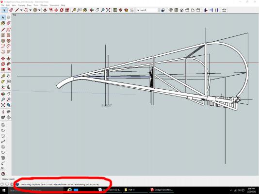
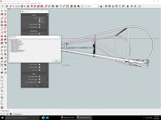
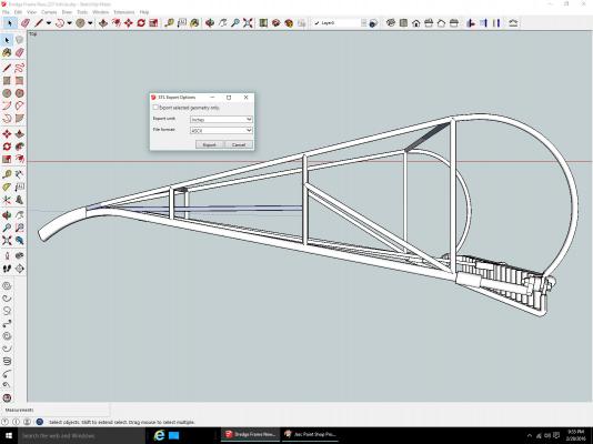
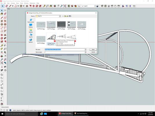
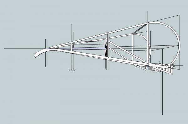
Part 15A This section will cover cleaning up the drawing, and processing it to prepare it for review by the Shapeways checking software. The part I will be using has some errors in it, this is due to it being an earlier version, than the final part. I discussed in the earlier post some of the problems, and solutions that might have to be looked for, while you are drawing your parts. I will be going back to the dredge frame for this and the next post. It has more extra “things” to work on. As part of the processing/checking steps, I use a new program for additional checks. It is netfabb Basic. This is the free version of this program. It has more features than the checking I use it for, but I have not explored them. I just use it for those checks. The raw part is shown below. It has several guide lines that need to be removed, before we start the checking processes. I used these lines as guides while drawing the internal braces. First I used a plug-in to remove the extra external lines. It will also remove the internal lines that do not form edges of internal walls. So do not do this step until you do not need the lines for future references to place new sections!! The plug-in used is CleanUp3, available free from the Extension Warehouse. To use it go to the Extensions Menu, select CleanUp3, then either Clean or Clean with Last Settings. The first time you use this plug-in, you may want to select some of the non-default options, after that first time, you can use the Clean with… selection, it just saves a few steps in the process. If the Clean item was selected, the menu shown below is displayed. If the Clean with… item is selected, the cleaning operation is run without this and the next few steps being used. Change any options you want, then select Cleanup. After several seconds, to several minutes, the operation will complete. There is a time to completion counter at the bottom of the screen. When it is done a couple of information windows will be displayed showing what was done. Just select OK to continue. Here is the part after cleaning. This clean up is not required, but it does make the part easier to see. Be sure to record the overall dimension in one of the axis, you will need this for scaling when submitting the finished part to the printing company. I used the X axis (length of the frame from the tip of the nose, to the furthest part of the curve of the rear of the frame. Note that the Cleaning operation does not remove any dimensions shown, they have to be removed manually, before or after. The checking processes are next. I export the STL file before checking and after each check. I first submit the uncorrected file, to see if it works. If it fails, I then submit the file from the first check, etc. Select Export STL… from the File Menu. This is another free plug-in from the Extension Warehouse. The STL Export Options window will be shown. Check that the units of measurement you are using is correct (inch or Metric). When correct select Export. The Save File window will be shown. Change the name, etc…, if desired, and select save. The first uncorrected part STL file has been created. Do this again after using the Solid Inspector2 operation shown below.

-
Well I managed to get the desktop running, I don't know for how long, but I was able to generate the pictures for the next to parts.
-
No its the motherboard, or CPU. Had three different PS in it 2 from working computers. It started to cut out while was working on it. Now nothing. I've disassembled it cleaned it. Checked the power switch, etc. The only thing left is to try forcing the ps on, but that is not a permanent solution. A new MB will have to wait until at least April, I have to take my wife to several different doctors this month, and that will eat up all my cash.
-
Work on the Carrie Price will resume shortly. I've been adding a room to the interior of my shop. In the past only 1/2 of the building was finished, and I have been slowly expanding into the rest of the 13' x 15' area. It was alright last summer, but I did not have all the insulation in the new section, and I could not keep it warm enough to work in there this winter. While working in the new area, all the stuff that had been stored there was piled up on and around the workbench. Living on a fixed income makes for compromises. I've also been spending time on the drafting needed for my 2D to 3D printed parts tutorial, and recently my desktop died. The laptop I am left with, is barely powerful enough for CADing, slowing that thread down too. I have progressed far enough to move the workbench into the new area, and I should be back on track by the end of the week.