thibaultron
-
Posts
2,952 -
Joined
-
Last visited
Content Type
Profiles
Forums
Gallery
Events
Everything posted by thibaultron
-
 Why not call them and ask? US manuf. , at least seem to be cooperative in such maters.
 -
They are, in my Carrie Price build log.
-
Crackers, both the subjects of the tutorial, are detail parts for two of my ship models.
-
Thank you!
-
Yes the next couple of weeks will be bad. A friend in Florida died last week, and we are going down to bring her dog to live with us. Next Tuesday, my Sister-In-Law goes in for cancer surgery.
-
I will probably be away for a week or too, due to family emergencies. See you when I get back.
-
As if I had not been slow enough on this log the last month, due to a friends death, and other family emergencies, it will probably be at least a couple weeks until I can get back to working on my model. The other problem I'm having, is that with my expansion of the shop, the heater can no longer keep up, and it has been a high of about 50 F in there. Next month I'm going to install more insulation.
-
Frank. Thanks for the great info!!
-
I am just trying to help others who can use this info. I think of this as another type of build log.
-
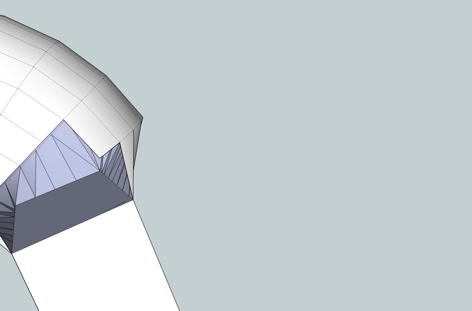
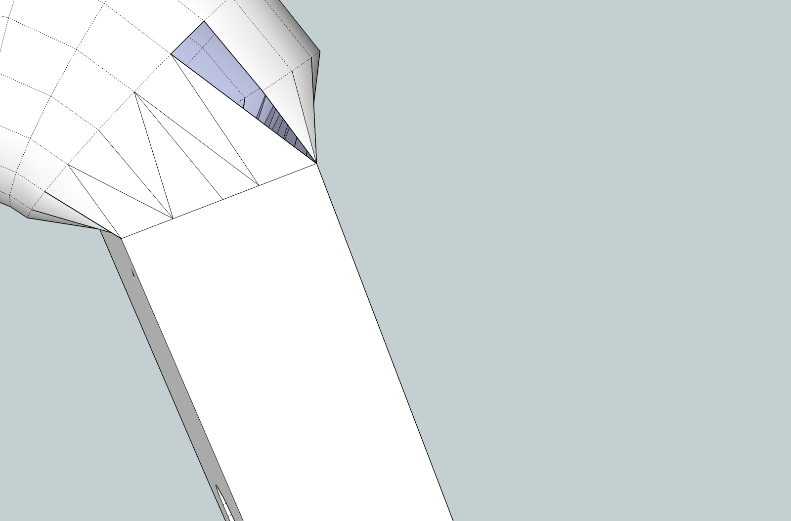
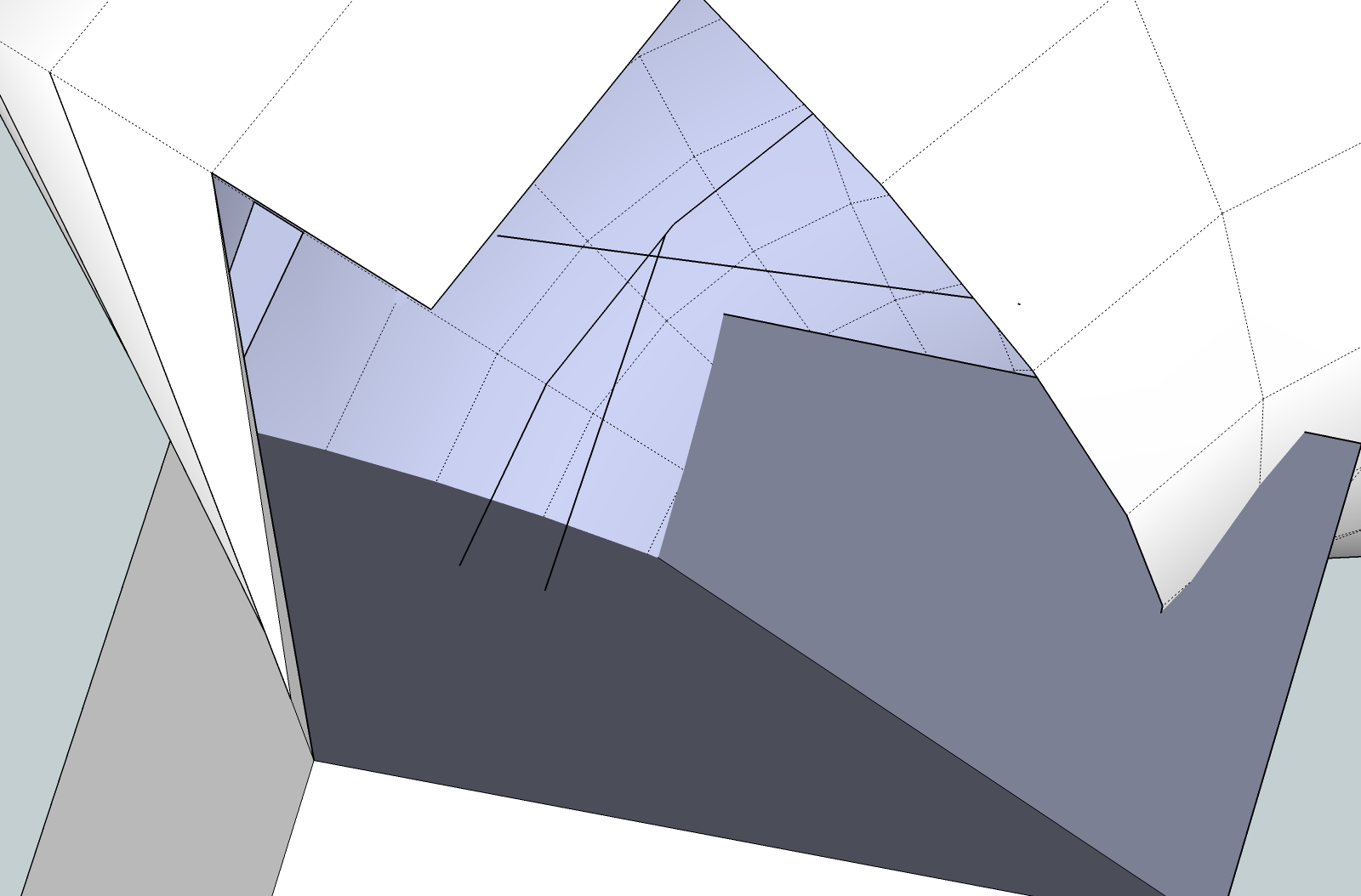
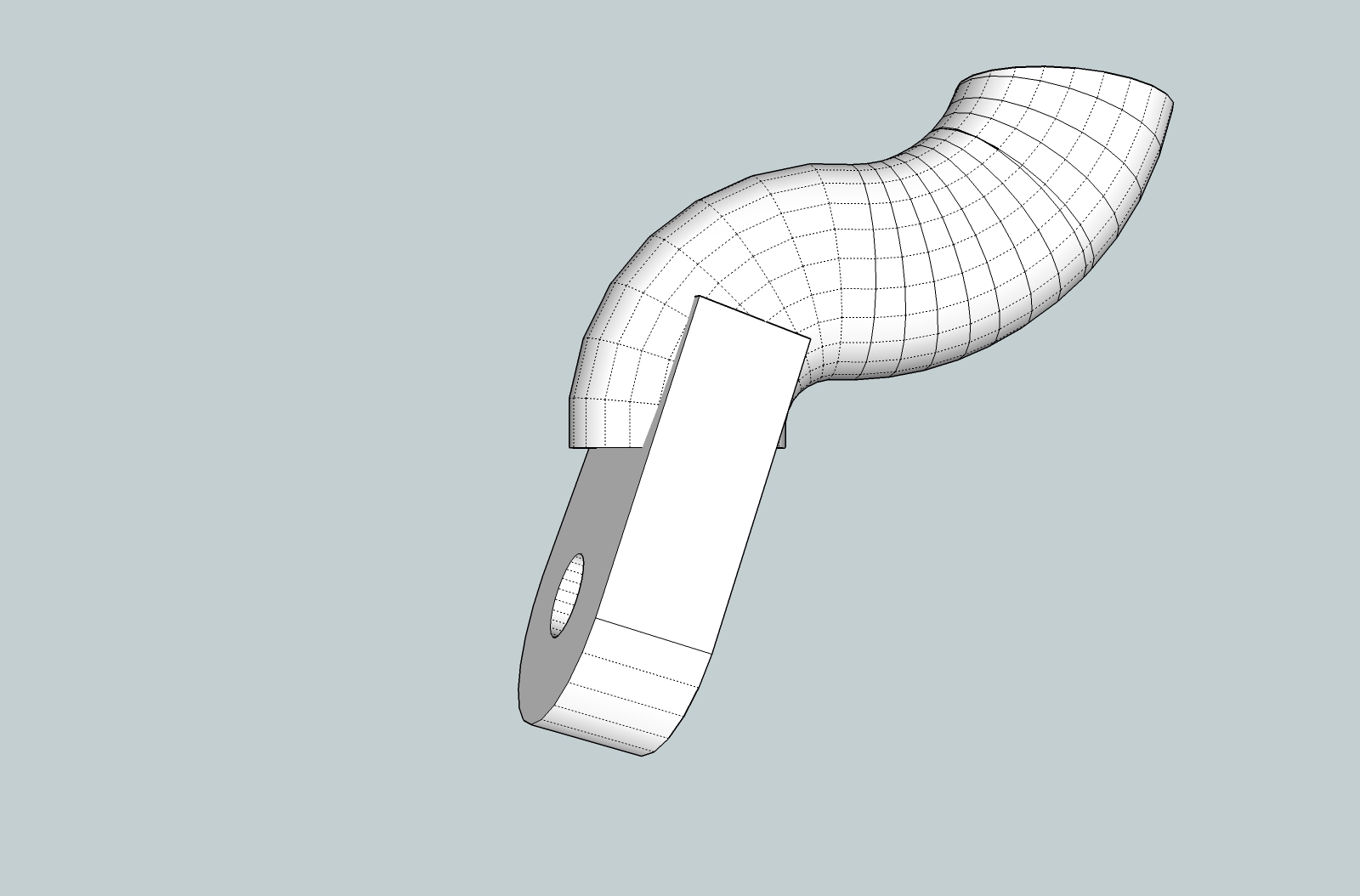
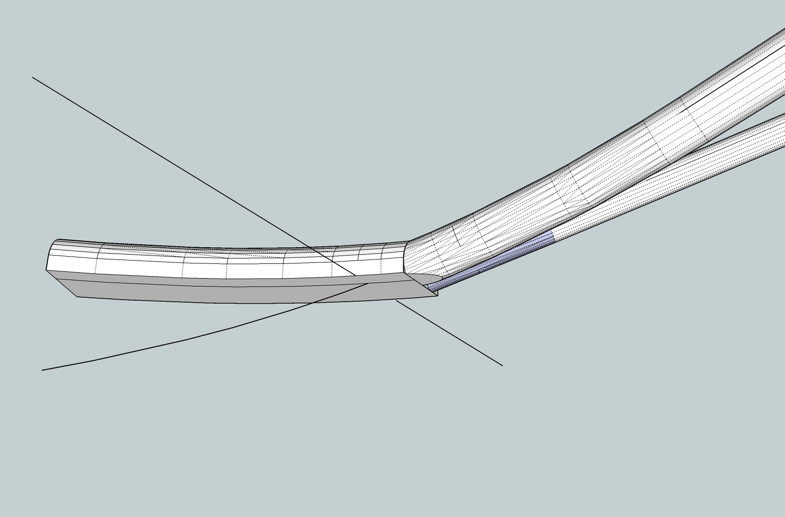
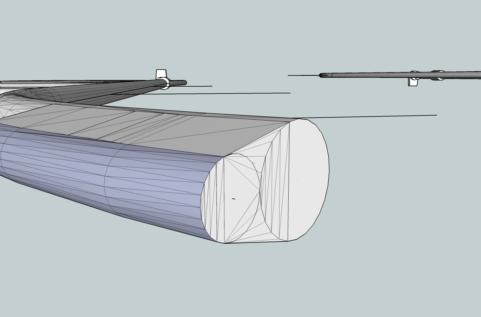
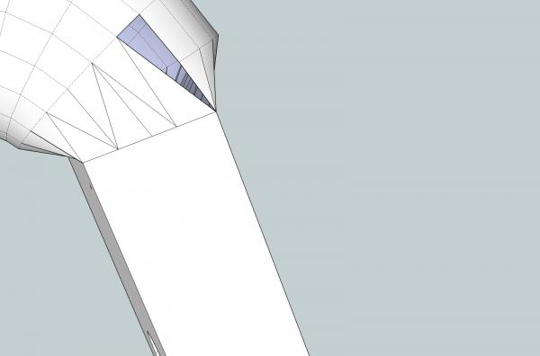
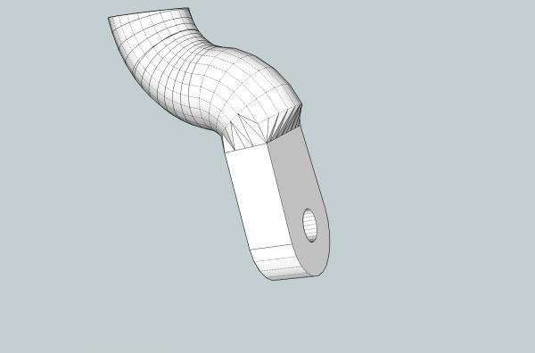
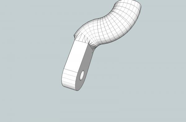
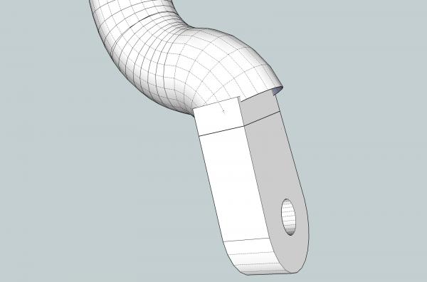
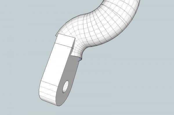
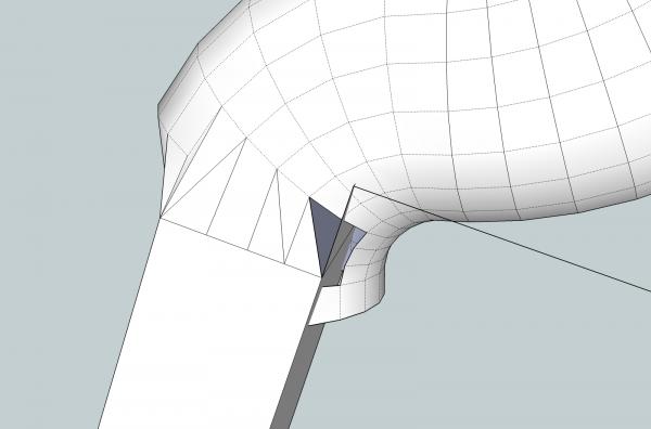
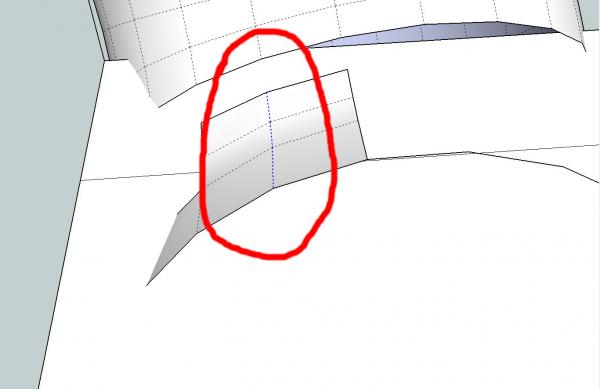
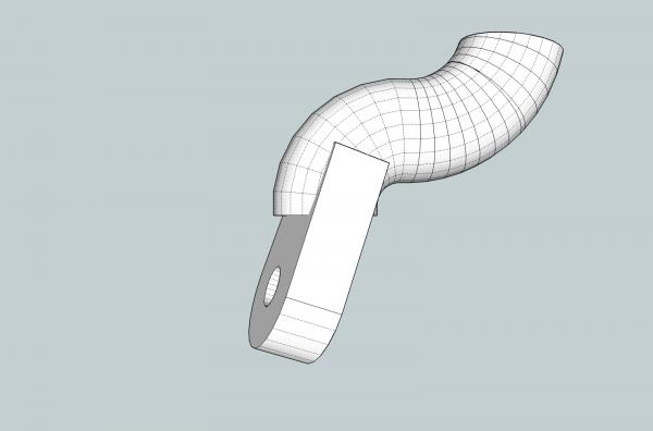
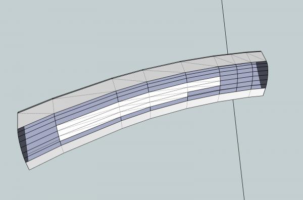
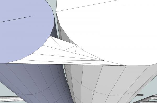
Part 10C The back side was treated as with the others. On this side I cut away less of the curved area, As this side already slopes more toward the tab's surface. The last side was then connected. Note that I again redrew the corner to include the full length of the adjoined curved surface. These are pictures of the completed end. Looking at the end, I decided that the slope of the first side was to sharp, so I redrew it going one line of surfaces back. Next time back to the winch drawings, and the point I had originally planned to start, before I decided that I needed to cover the previous material first.


-
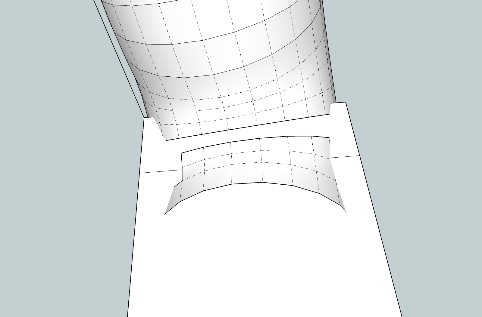
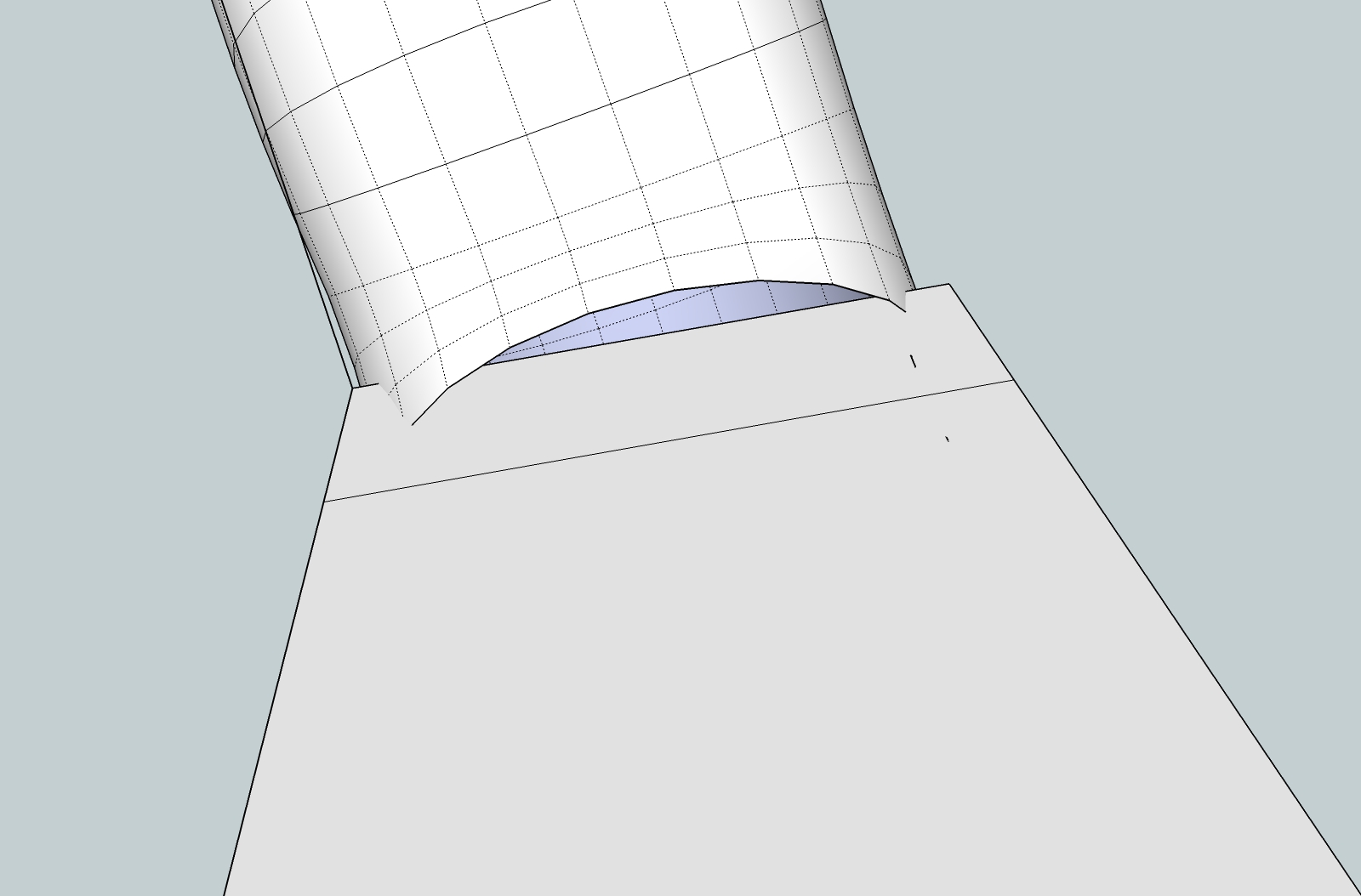
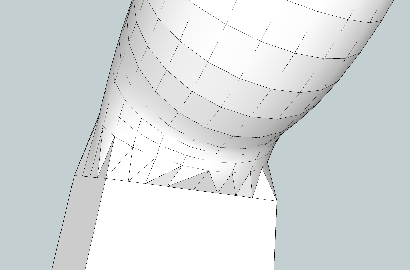
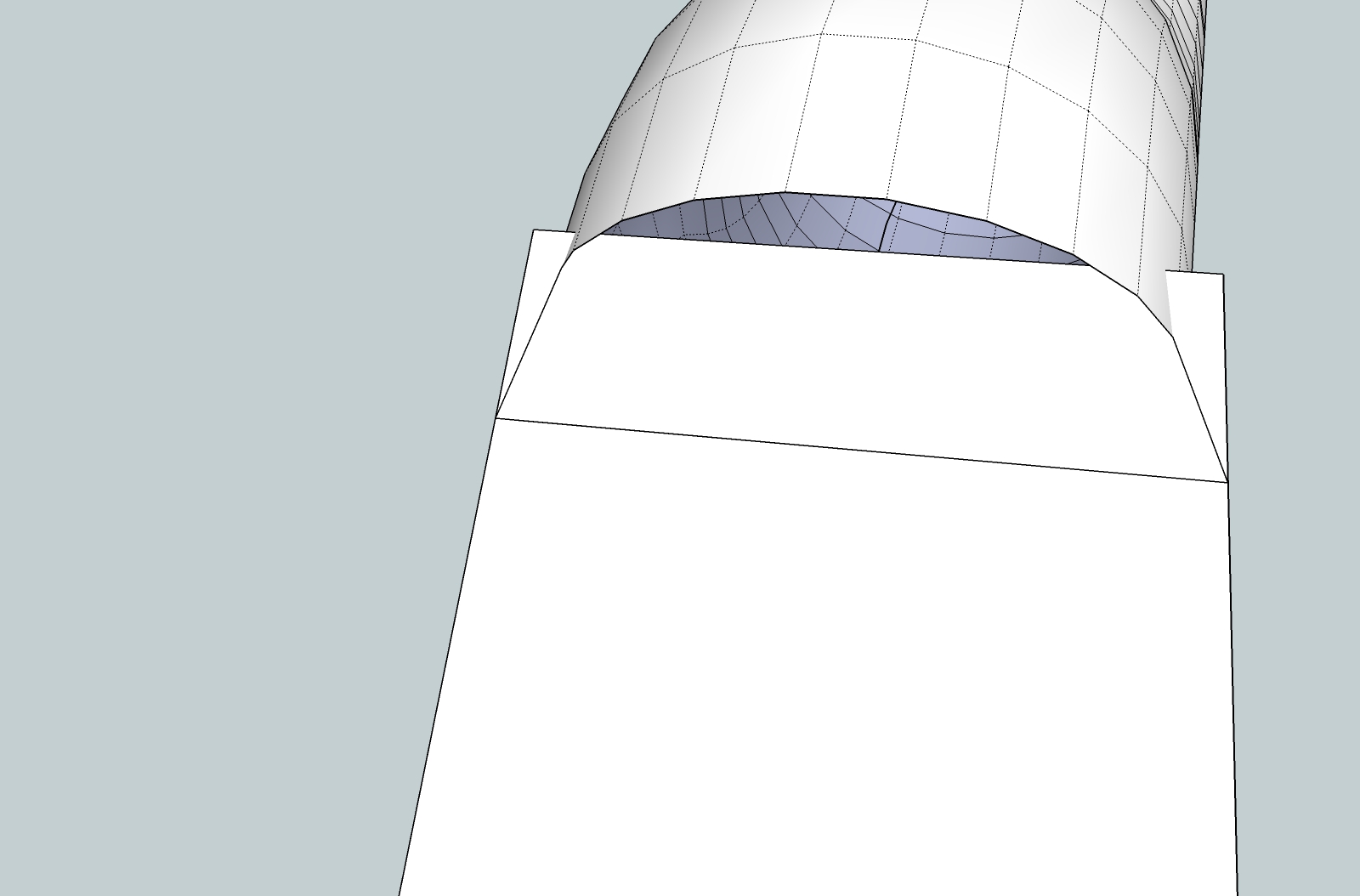
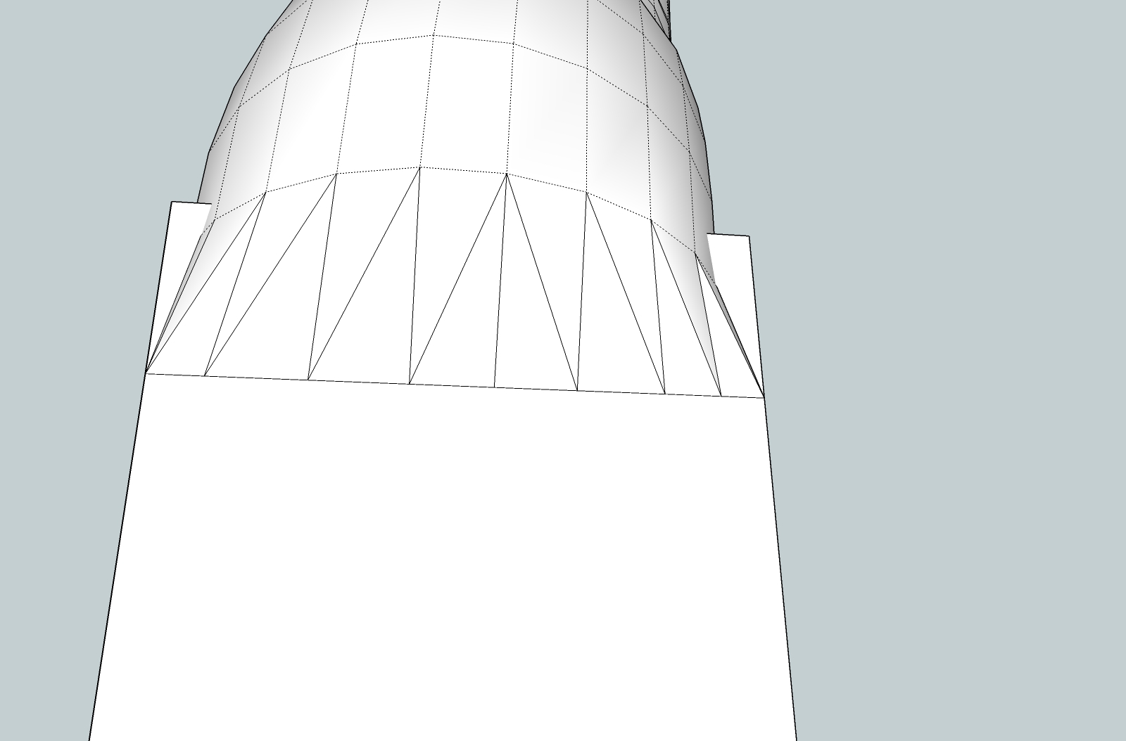
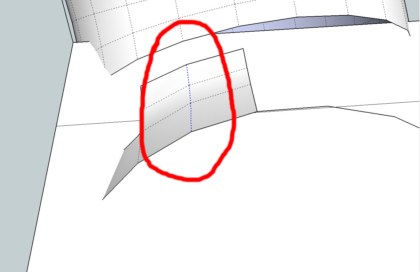
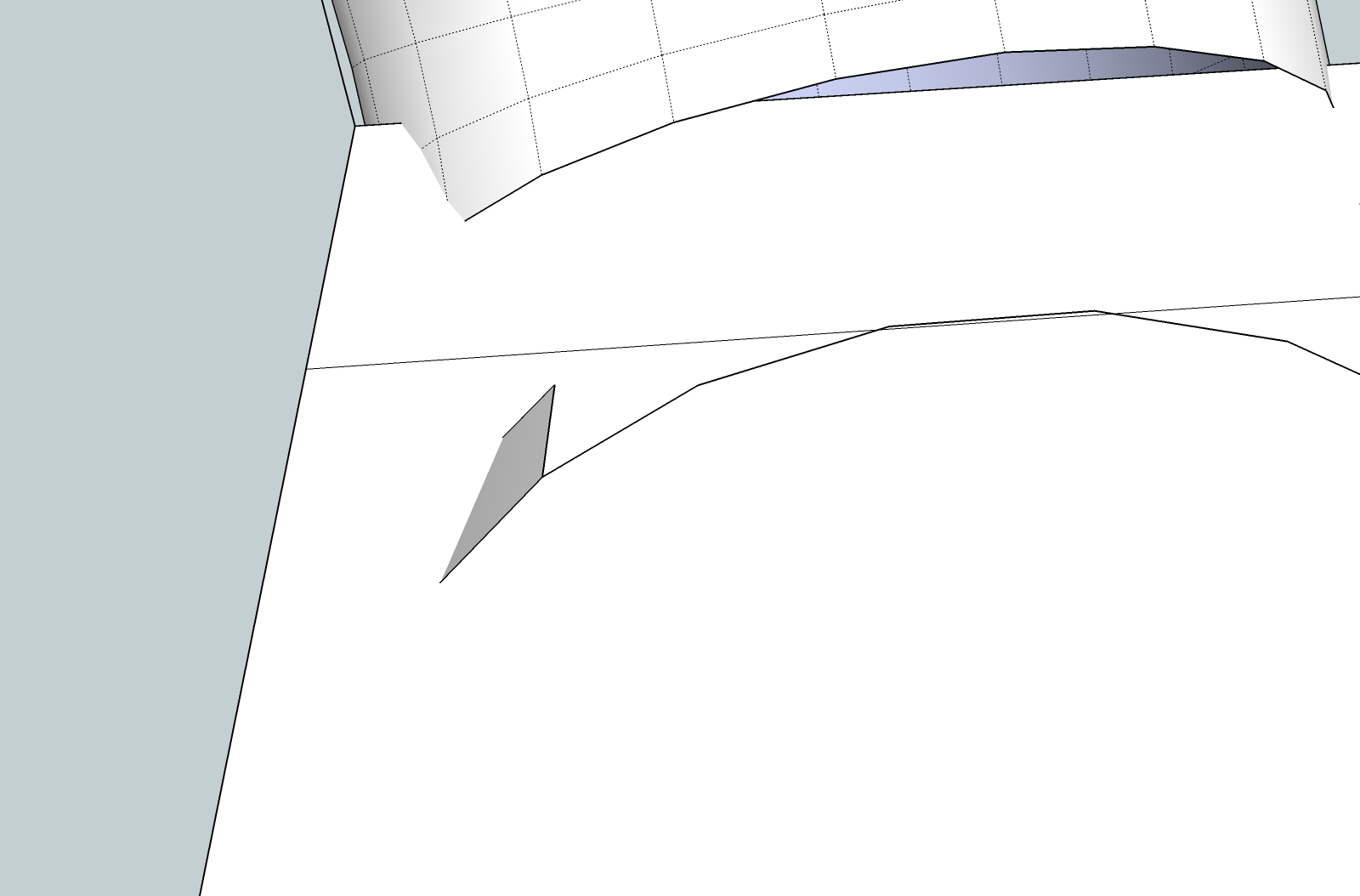
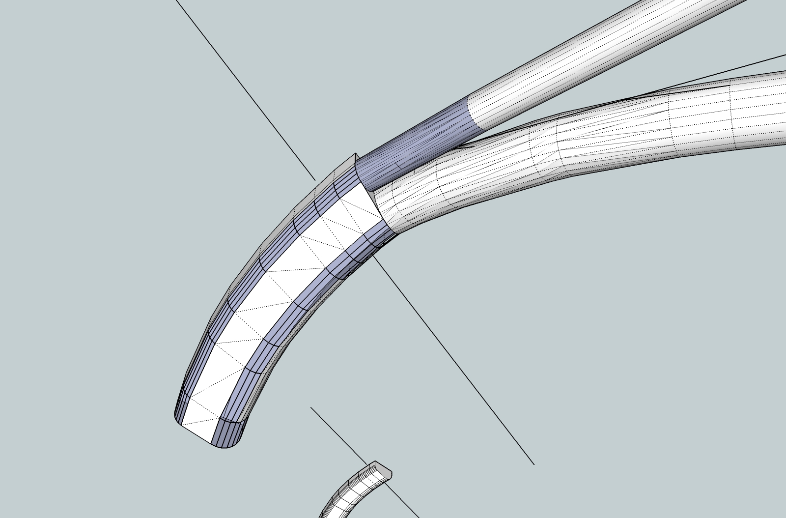
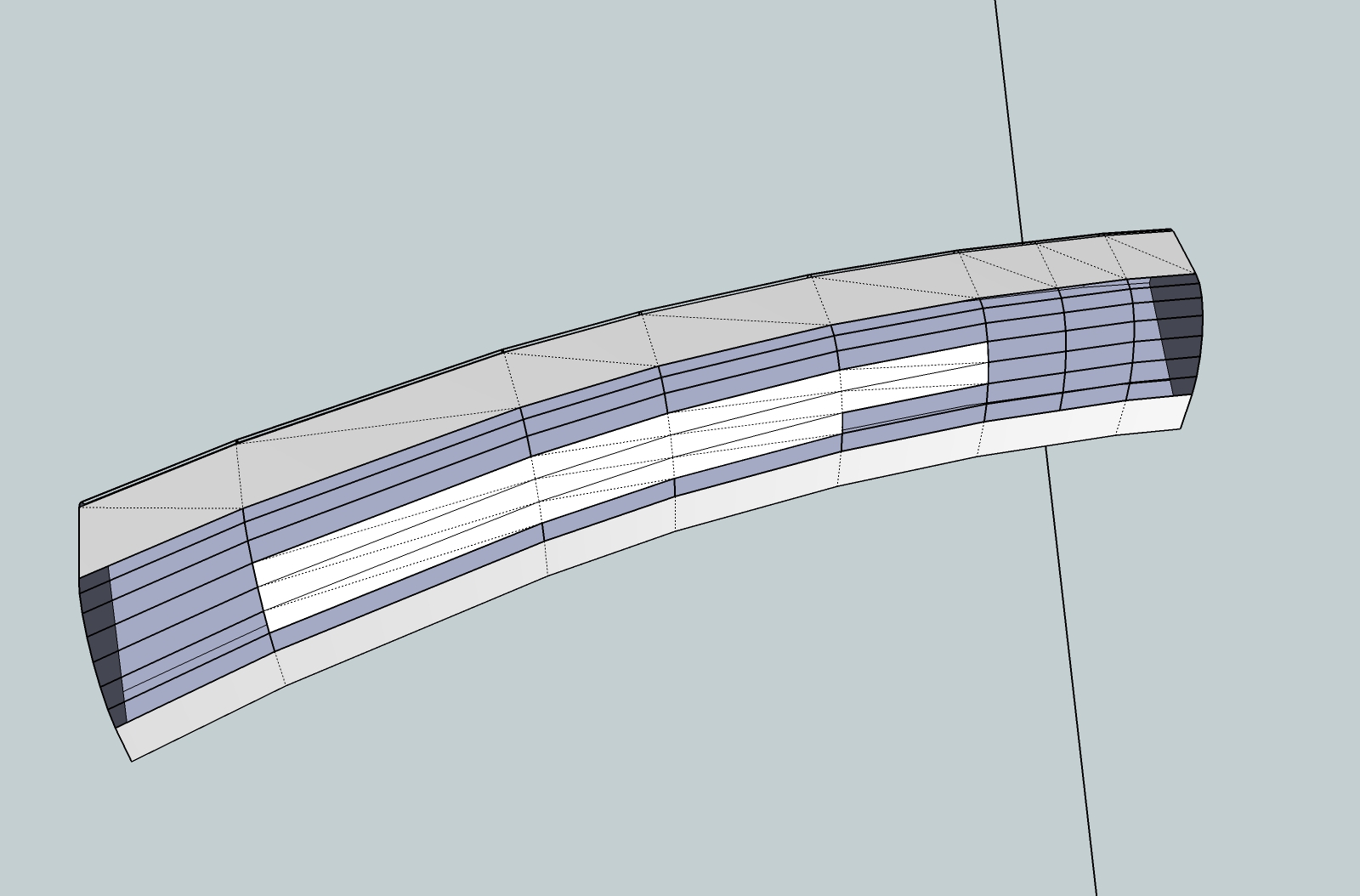
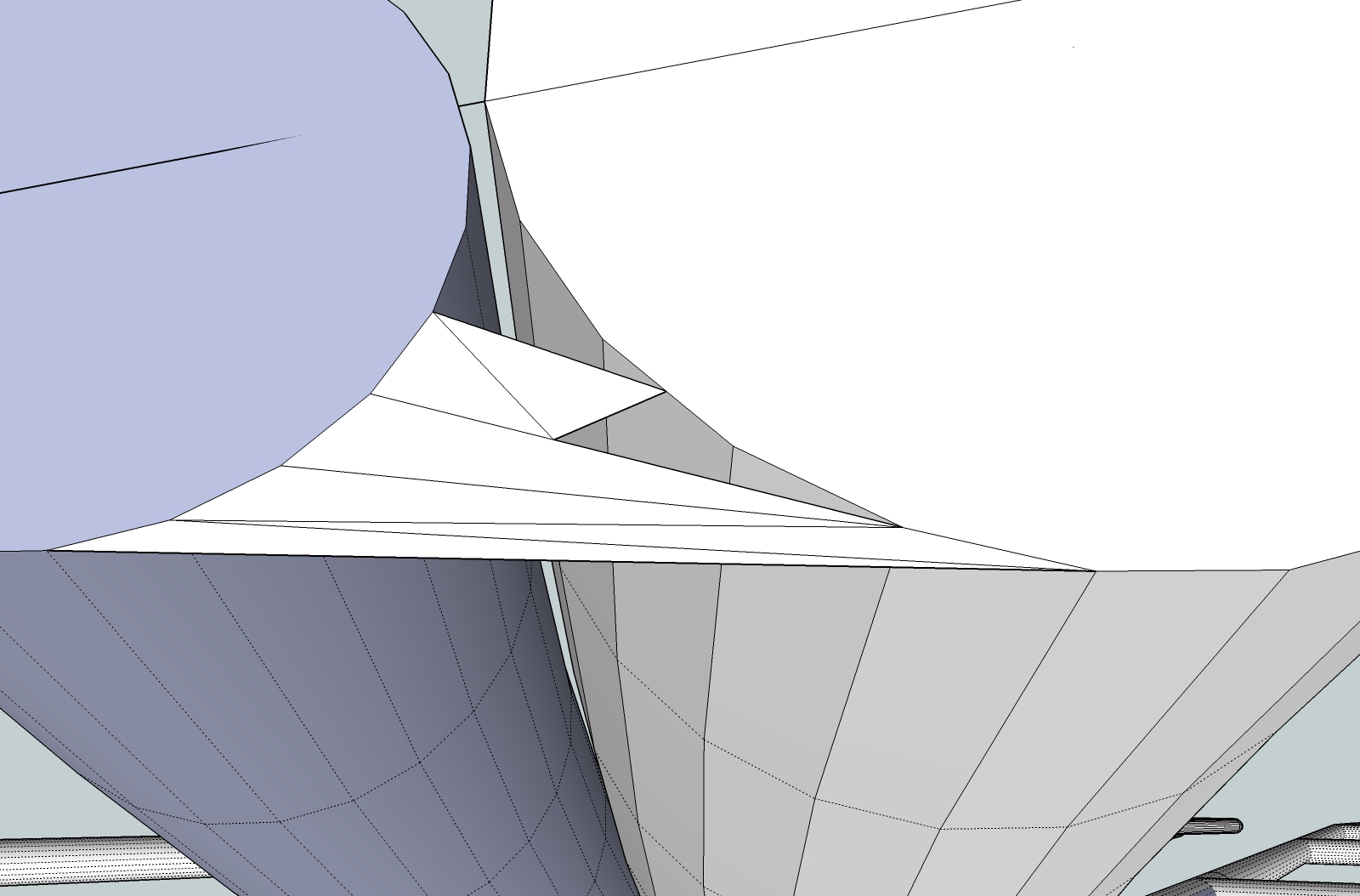
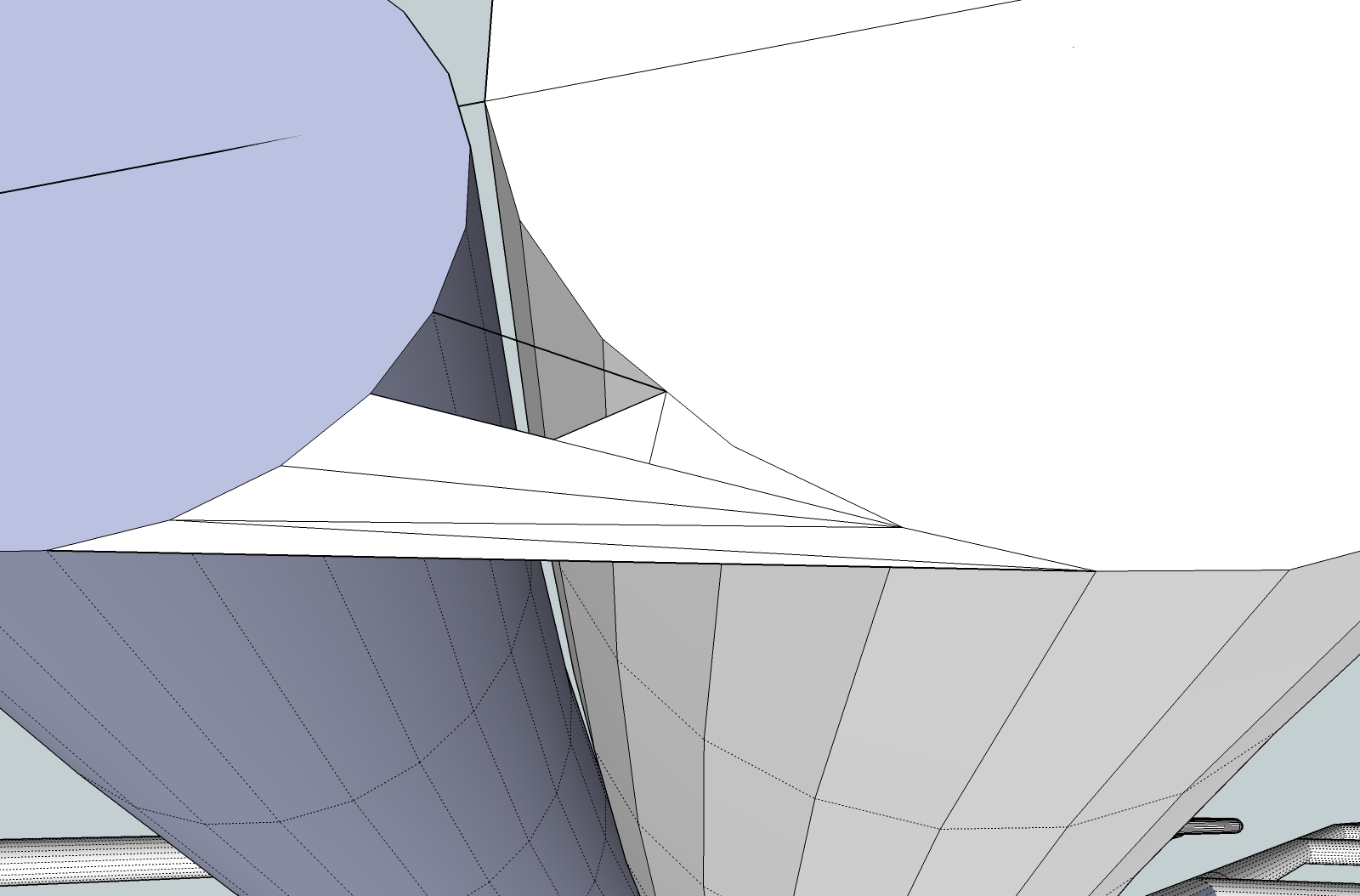
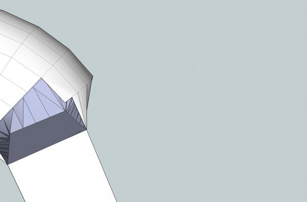
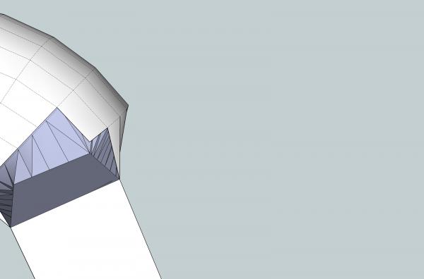
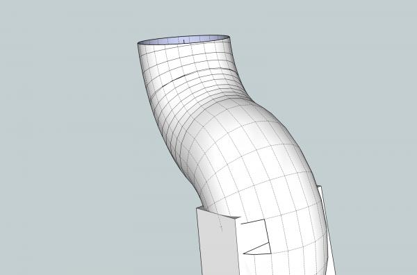
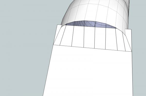
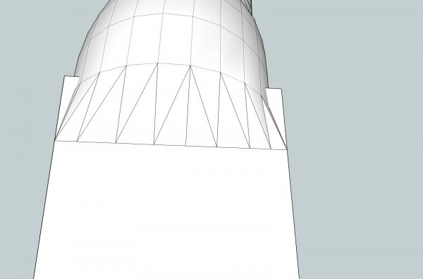
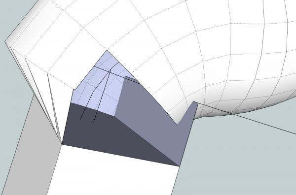
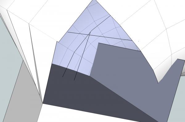
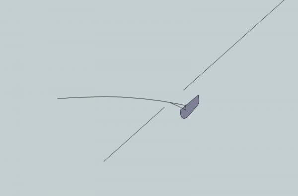
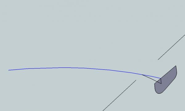
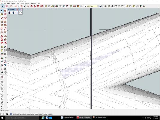
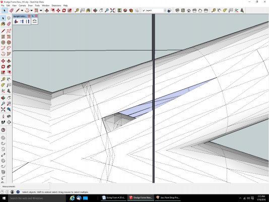
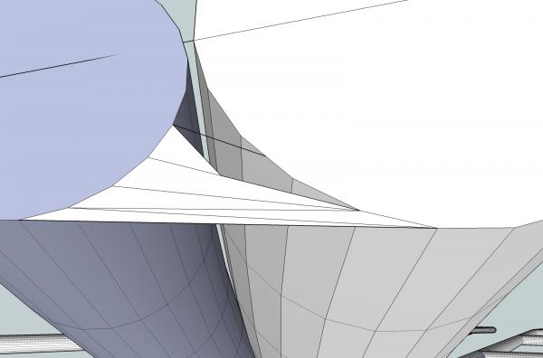
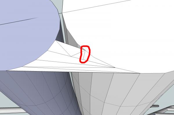
Part 10B Next I took a face, and decided where the best line was to start the transition on the side. I started with the hump of the curve, as that will be the side with the most difference between the curved and flat surfaces. I removed the two surfaces that touched the flat, at the point I wanted to start. Then I drew a line between the two intersections, to use as the end of the transition slope. Next I erased the surfaces between the ones I just deleted. I erased the orphaned end of the bar, and extended the line around the entire tab. I will use this as the ending of the slopes around the finished transitions. If a blacksmith flattened the end, this would be how he treated all the sides, making them line up at the start of the flat area. At least, that’s how I would. I then connected the corners of the curved surfaces, to the edge of the line on that side. This ties the curves to the flat, and will serve as two of the corners of the transitions. When I am done the top section of the tab will have been erased, above the bottom of the four transition slopes. I connected the endpoints of the curves to the line, forming the outline of the transition. Using the triangle method I filled in the slope. Starting on the second side, I erased one row above the first, I erased one row above that of the first side, as the curved surfaces were closer to the flat surface of the tab. I also erased the upper area of the tab. On the left you can see that there is a corner left on the last curved surface, of that first side. I erased the sloped border line, and redrew it to include the full length of that surface. I continued in the same manner as for the first side, to fill in this one.


-
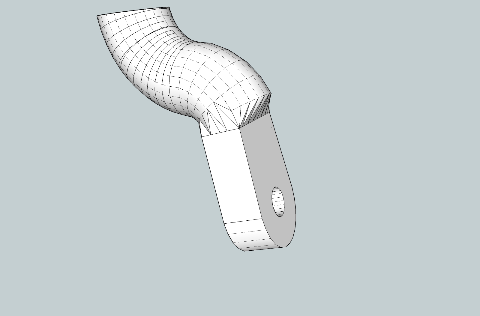
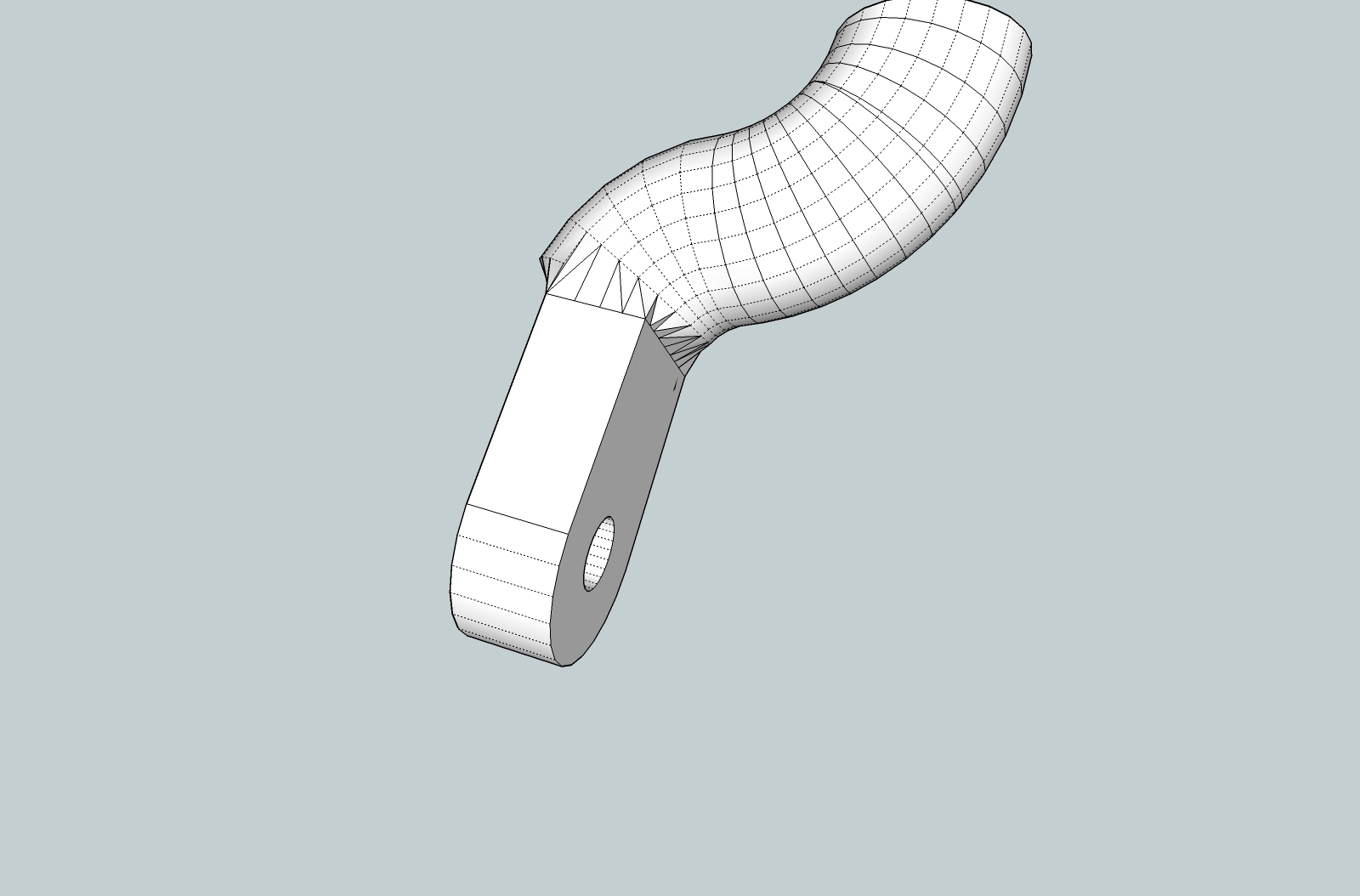
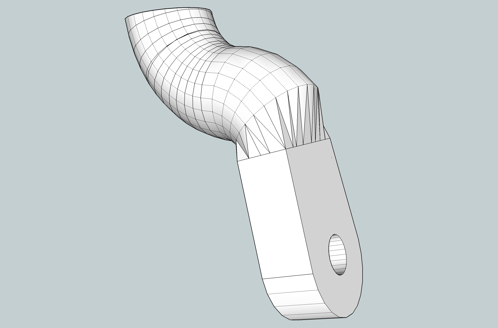
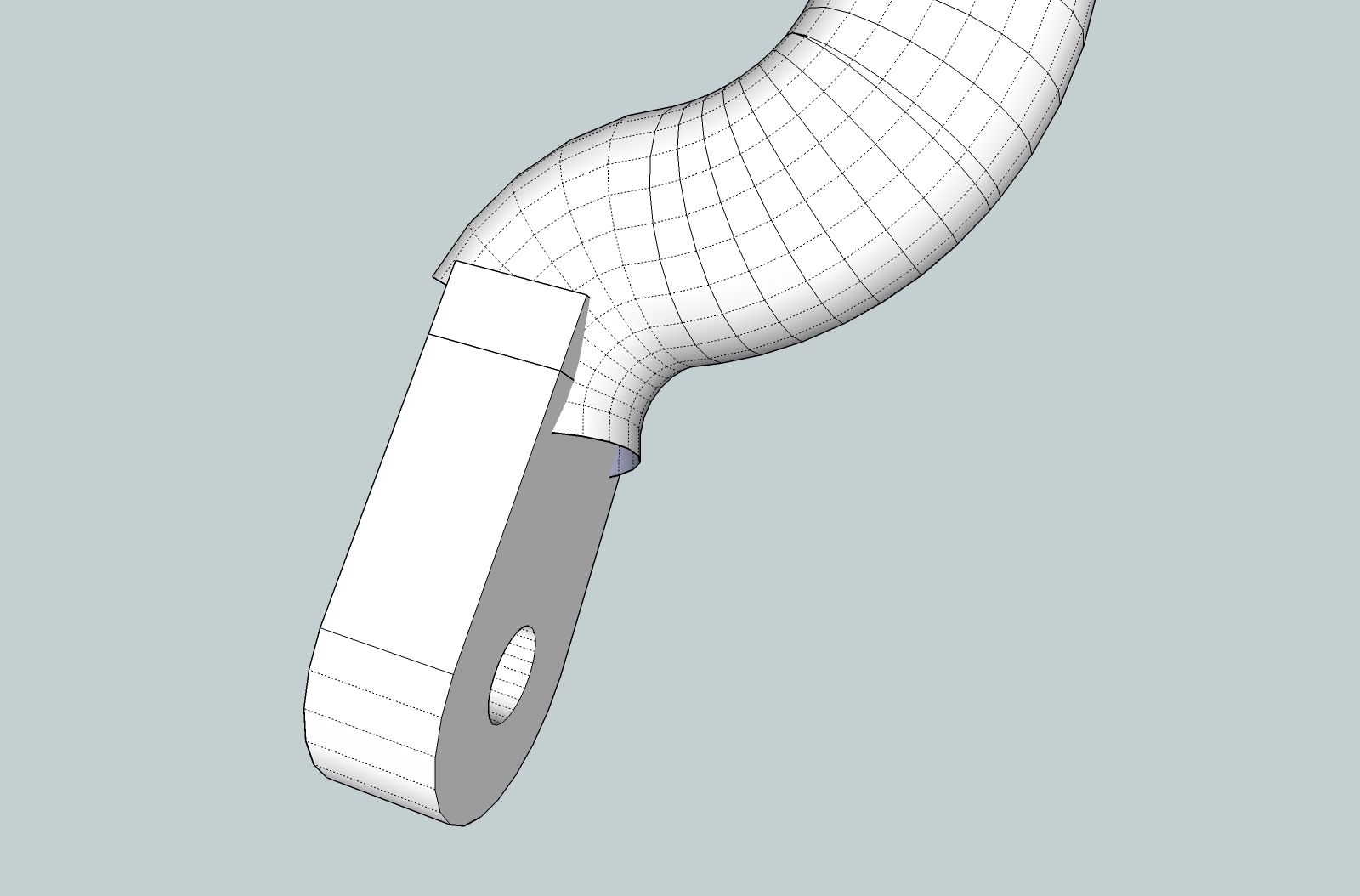
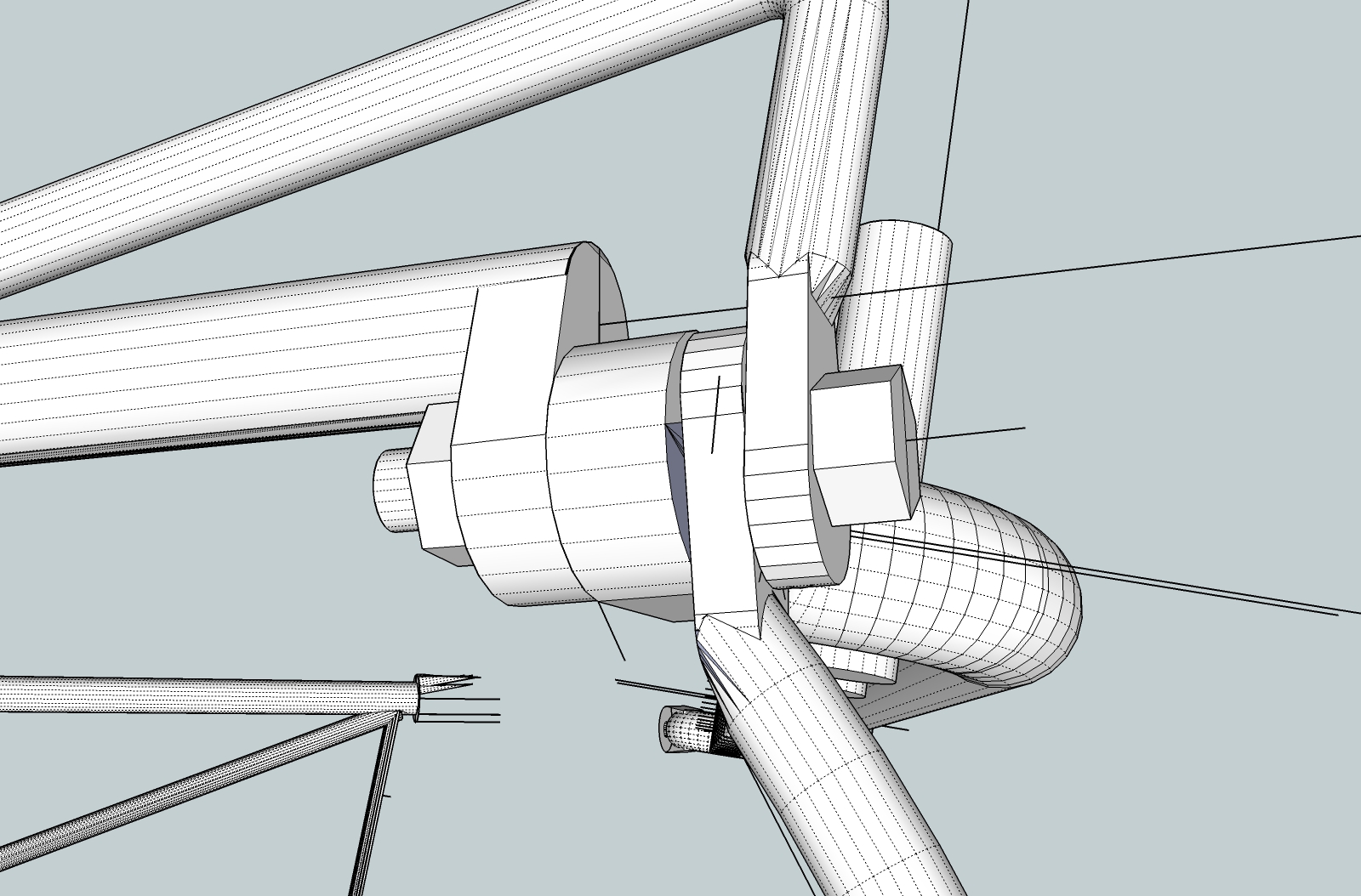
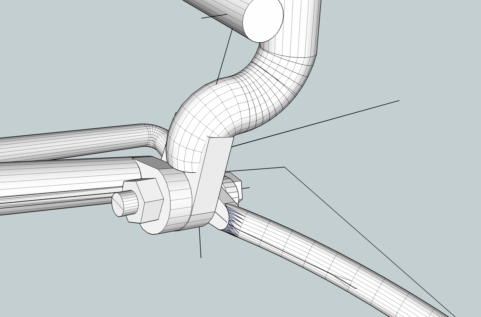
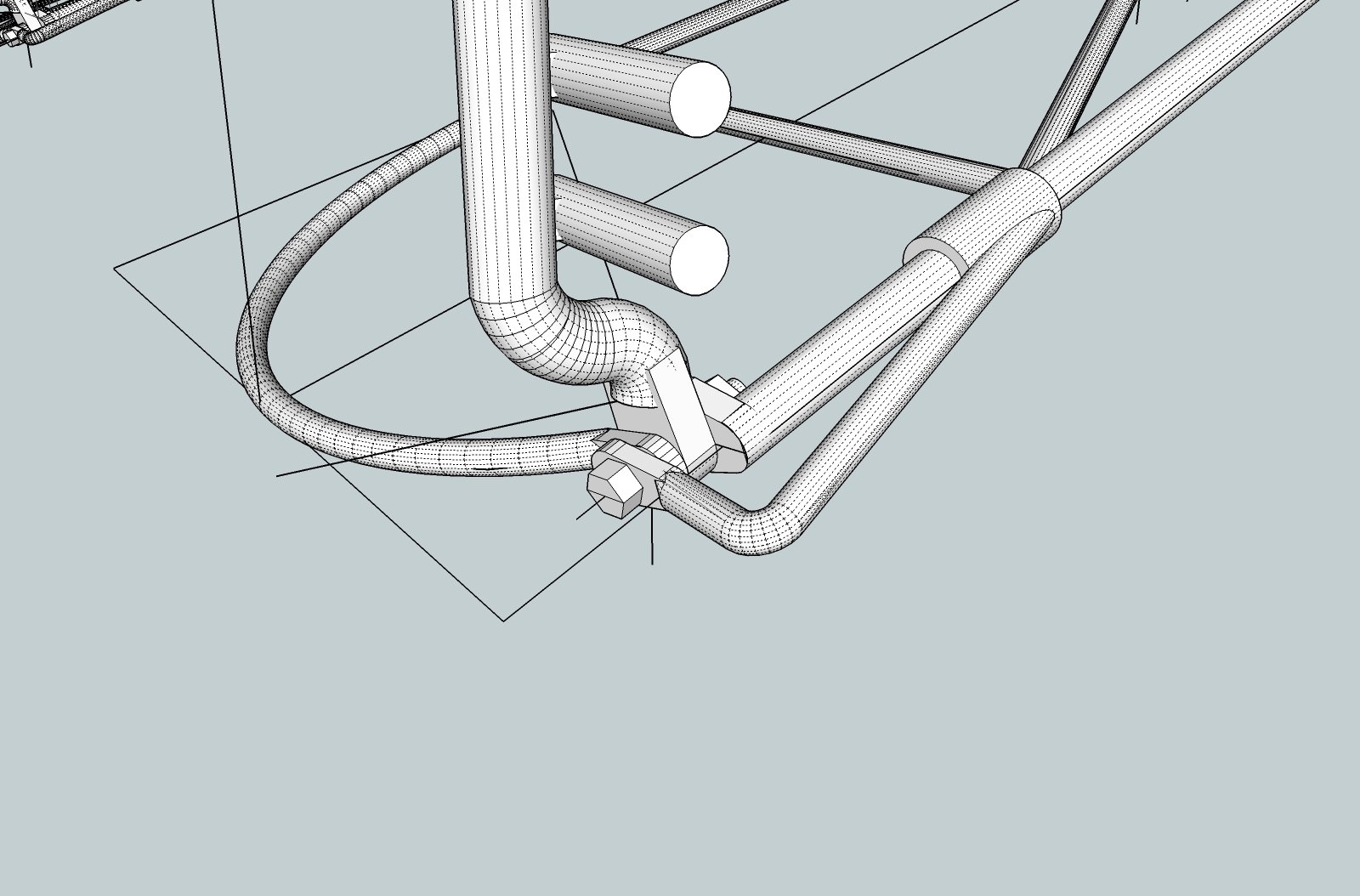
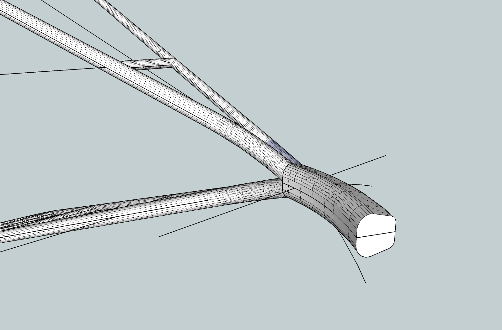
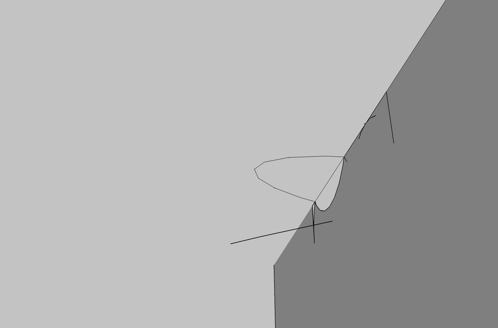
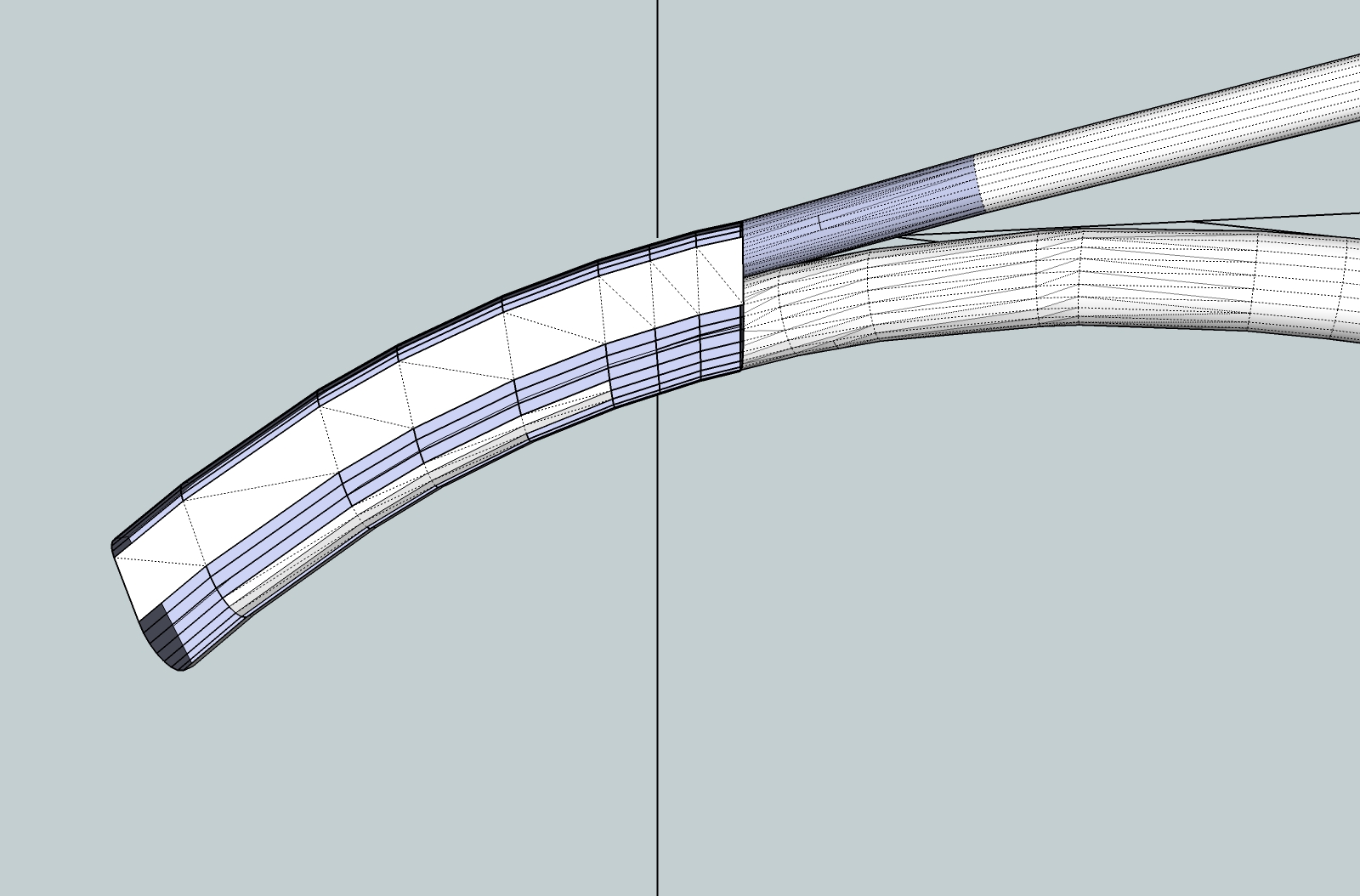
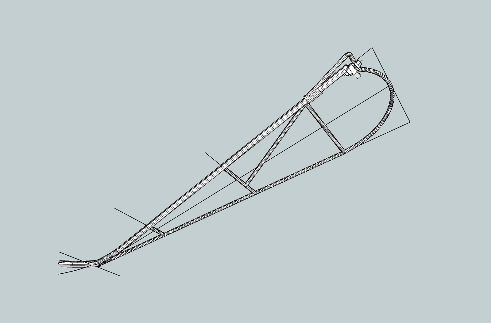
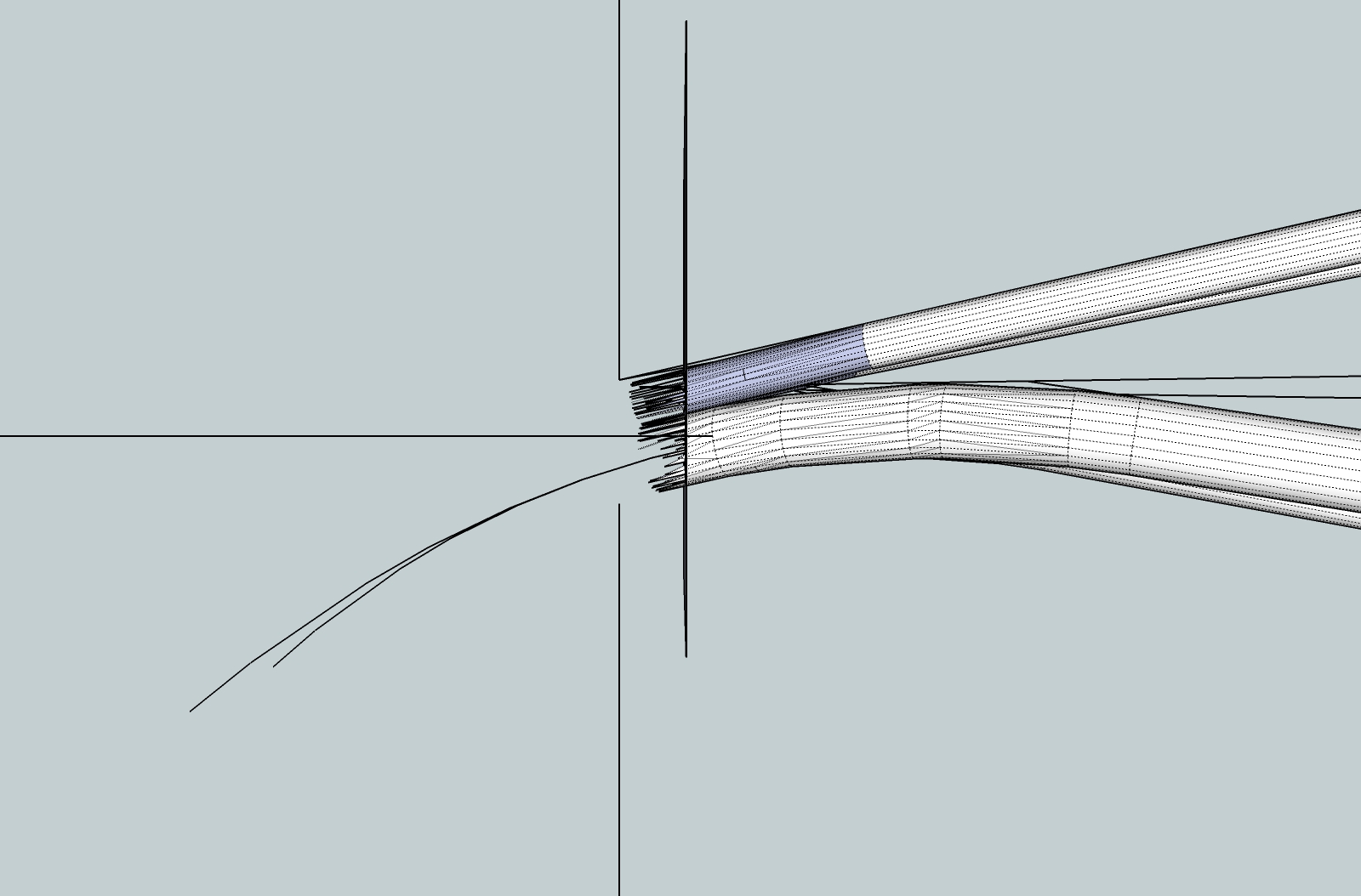
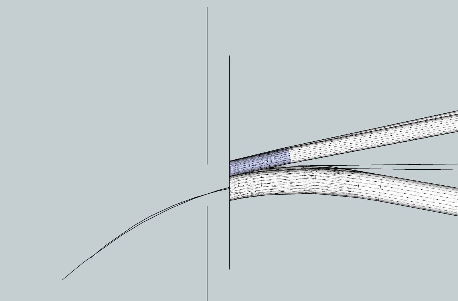
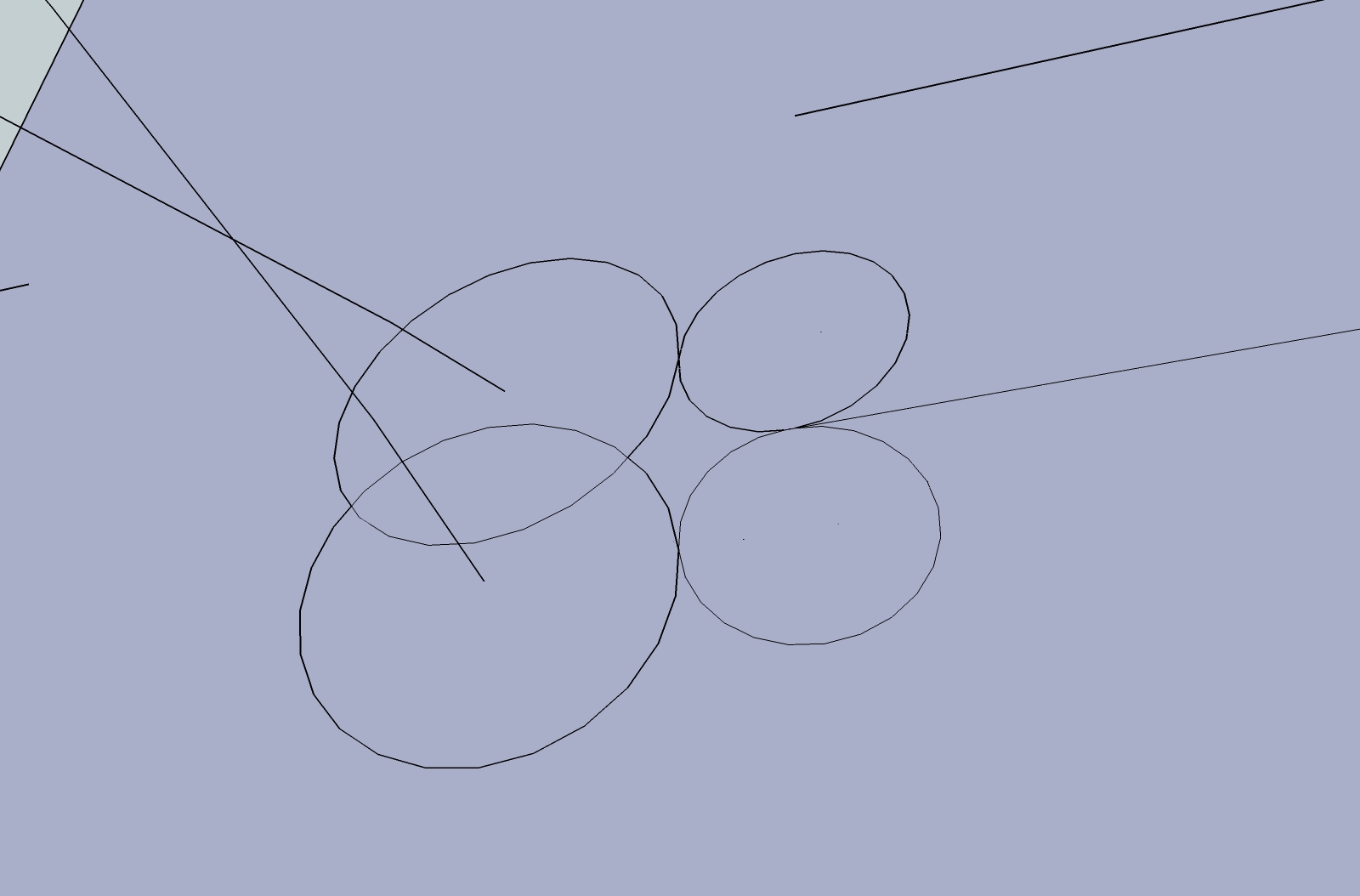
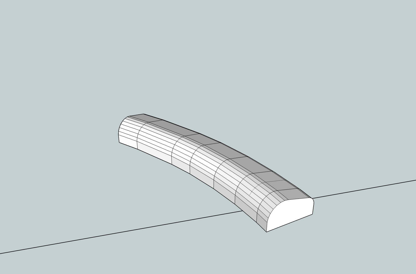
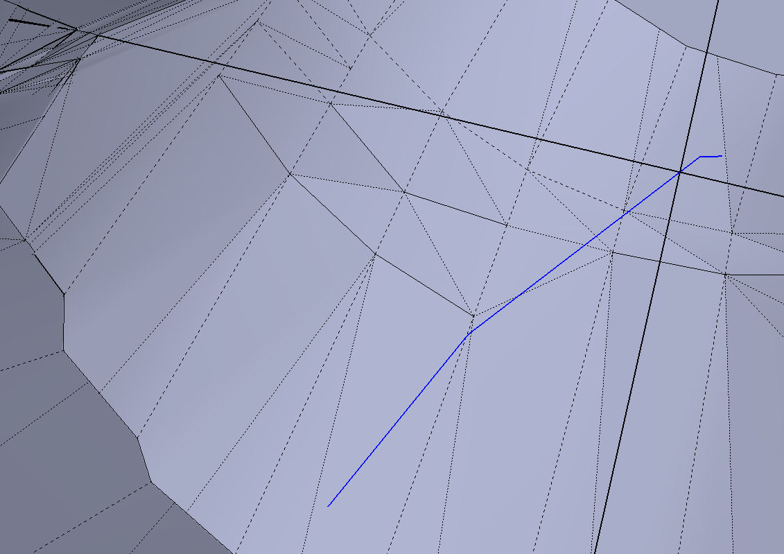
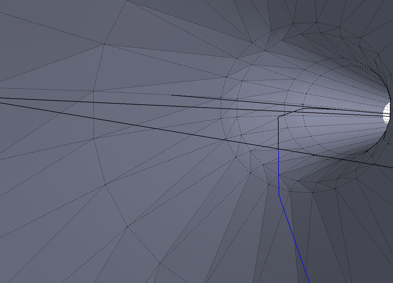
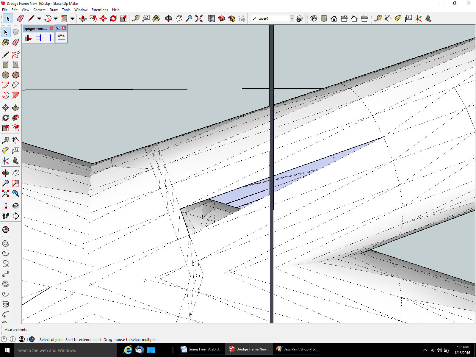
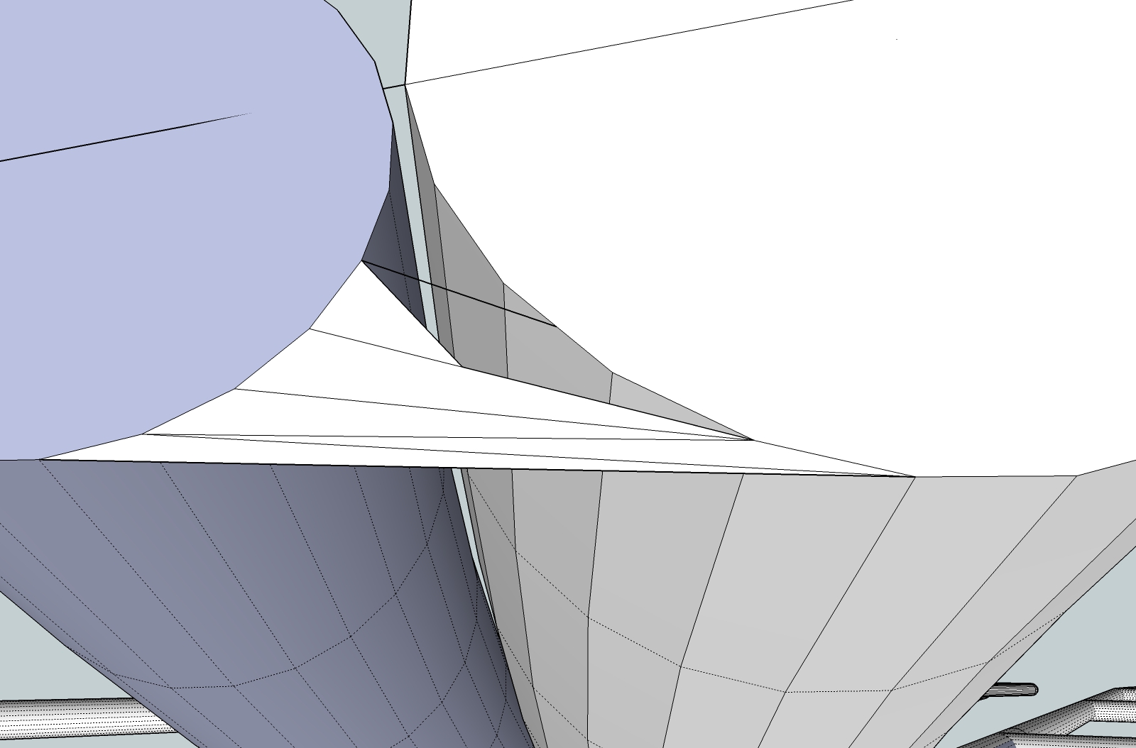
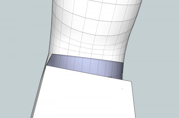
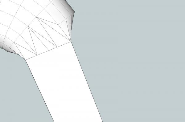
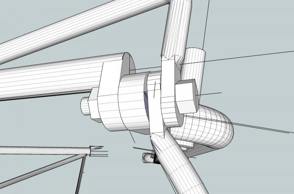
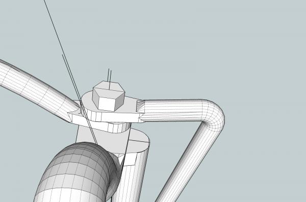
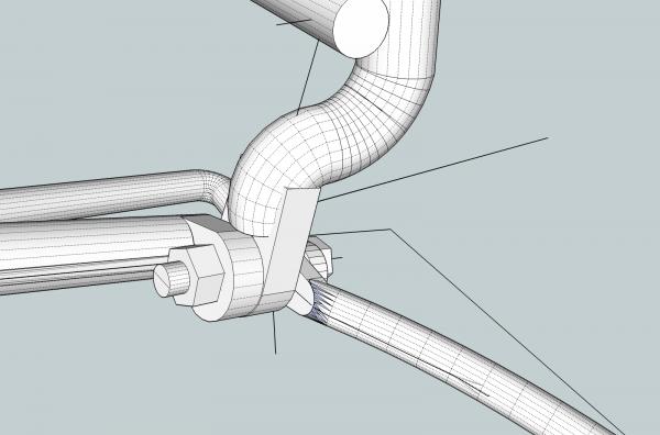
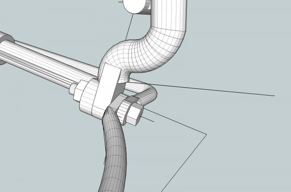
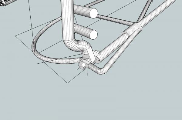
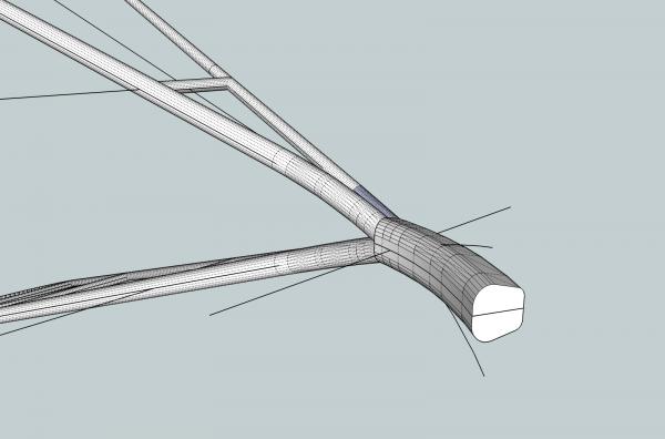
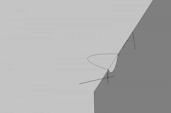
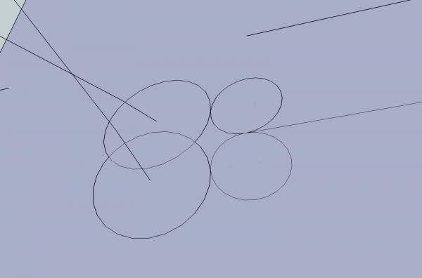
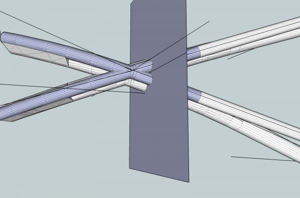
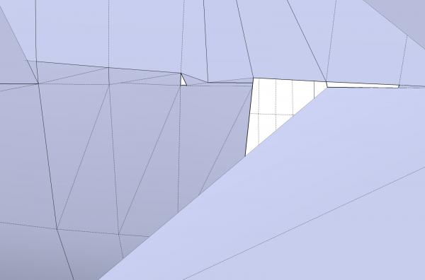
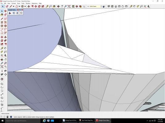
Part 10A Selecting an Object Hint In the tutorial below, I have to erase a fair amount of surfaces. To make it go quicker, there is a trick. If, for example you want to erase two adjoining surfaces, select the line that separates them. It and both surfaces will be erased. Without that line the surfaces now have an open side, and cease to exist. If the surface has one side that is a dashed line, select it, and many times the surface and the solid line will also be erased. I’m not sure why the solid line is erased, but it is. Transitioning from a Round Object, to a Flat Sided One This is how I did the transitions from the round bar stock of the frame, to flat sided shapes that represent the end that is bolted to the others. There may be better ways I don’t know, but I chose this method, it was simple and straight forward. On this frame the ends of the bars are flattened and bolted together. I figured that in the 1890s, this would be done by a blacksmith. I assumed that he would flatten the ends, making them a little wider. This would not leave smooth machine formed modern looking transitions. This allows me to justify my crude transitions. :-). In 1/32nd and 1/64th scales, they will be all but invisible any way. Here is a finished transitions on some of the smaller bars. For this part of the tutorial, I will be making the transition between the 1 ¼” diameter dredge bar, to its tab. The next three pictures show the starting point. The round bar overlaps the flat sided tab. In the picture below, I’ve erased all the other parts, to give us a better view of the operations.

-
I am not and expert, by any means. I just started using SketchUp about 3 months ago. There may be way better ways to do some of this. The content of these posts is what I have learned of its features, while doing these projects. I have been drafting for my own use for several decades, though.
-
I would say, just dropped. It would be to heavy to throw. I've never seen a picture, or any written material, on how they did it.
-
My next task is to redraw these frames, for a 1/64th scale skipjack. Even with the minimum print size limits, it will be near scale cross section. I could not even come close trying to fabricate them. I'm thinking of drawing up the trailboard base, and a railing that was misshapen on the kit. Buying material small enough for the railing has been elusive. I have a couple of kits that to save money, they do not include all the cannon, another plastic kit where one cannon was misshapen. Other small detail, barrels, fish traps. I saw one that was a whole bunch of blocks for a 1/200th scale modern warship, not sure which one. If you are really talented, scale crew figures. Not all of us can fabricate every detail, like the big guys, nor at my age, am I likely to have the time to develop such skills.
-
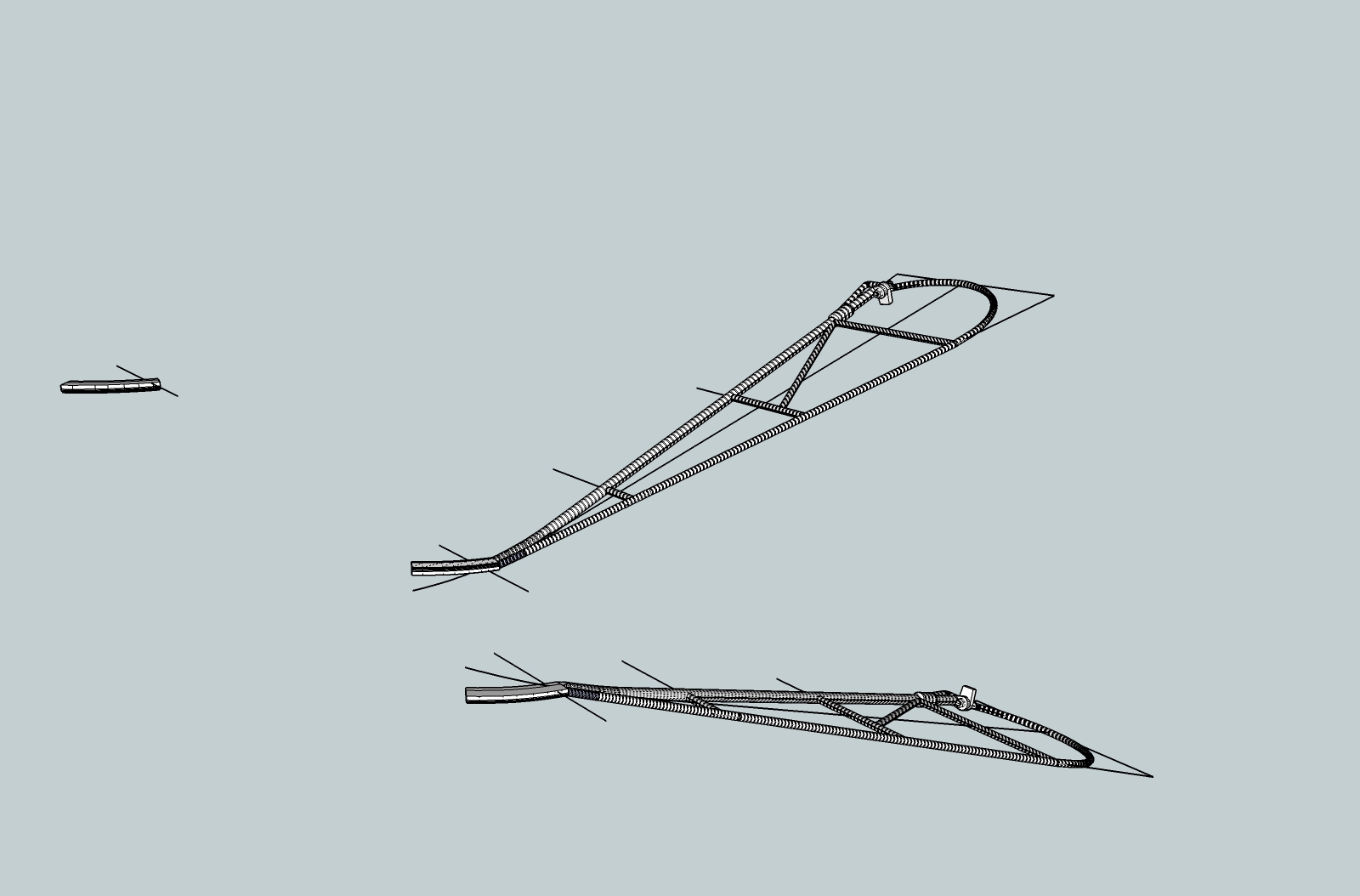
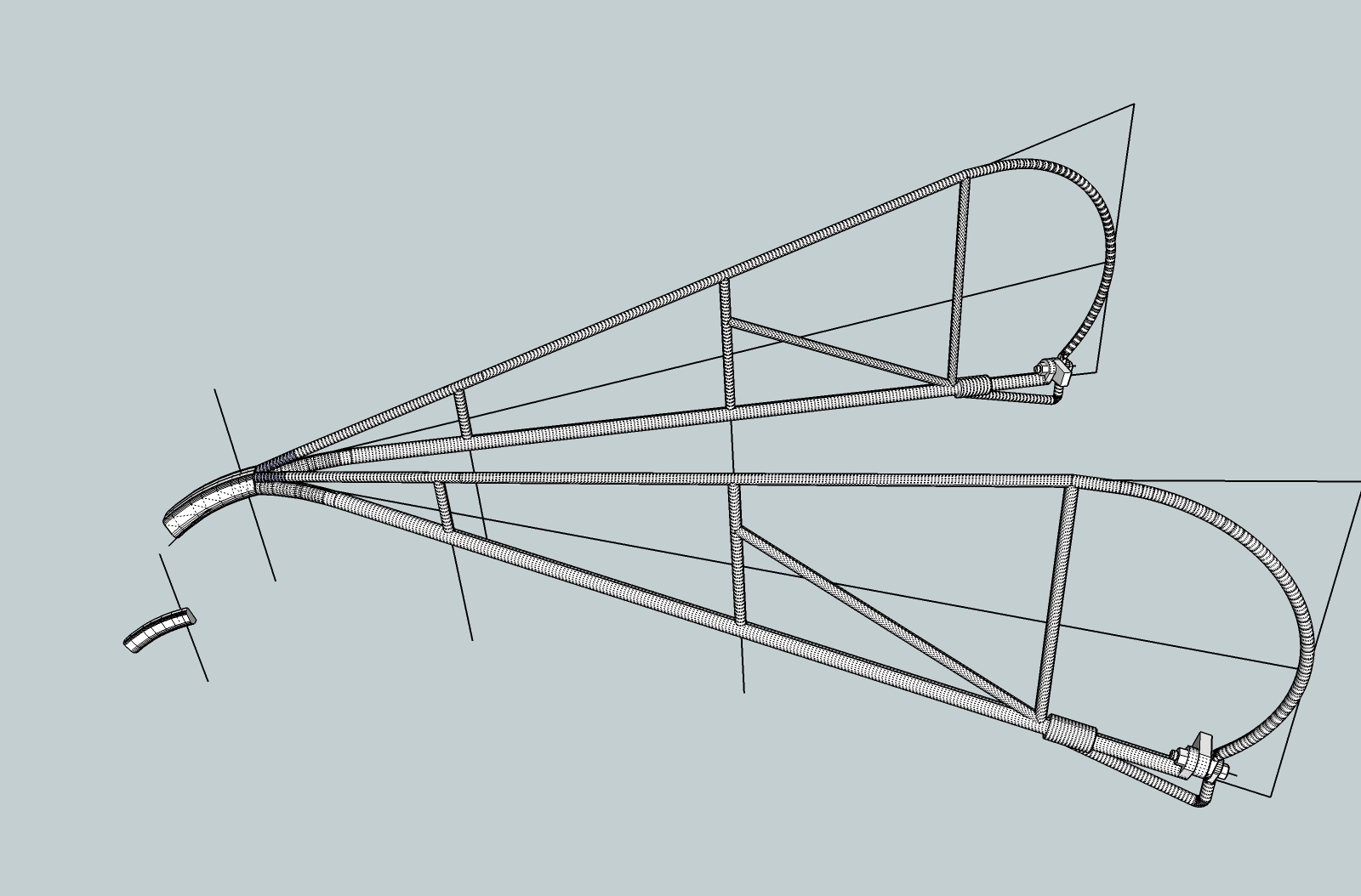
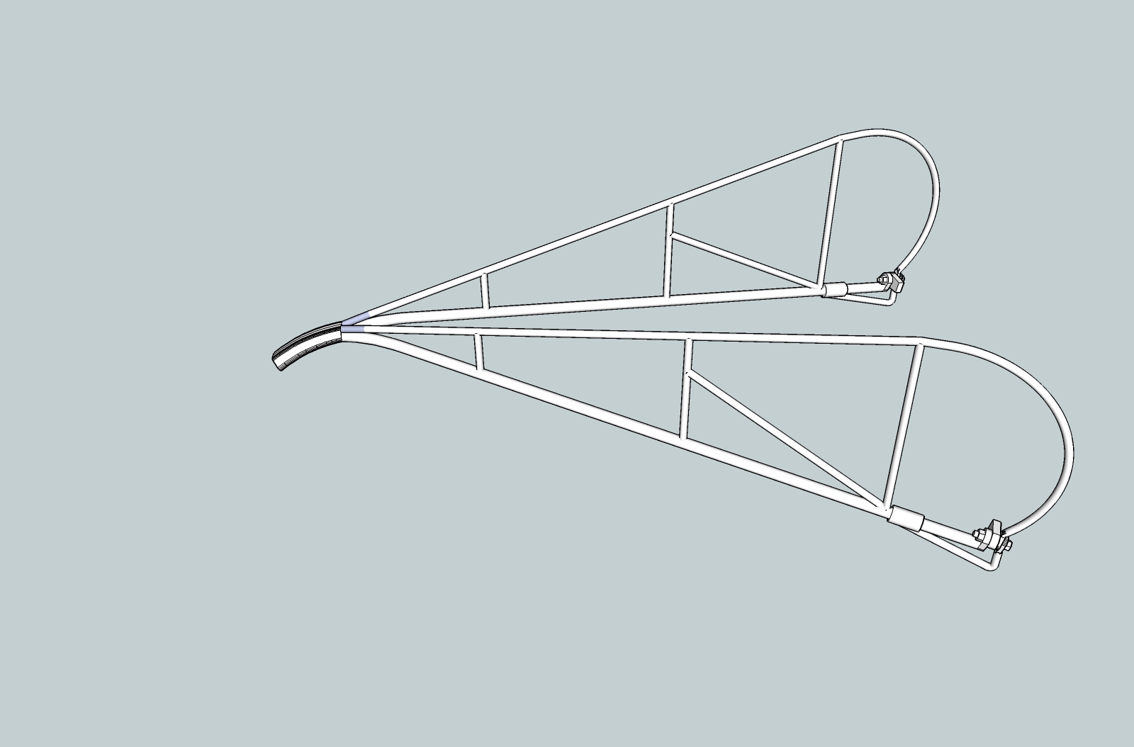
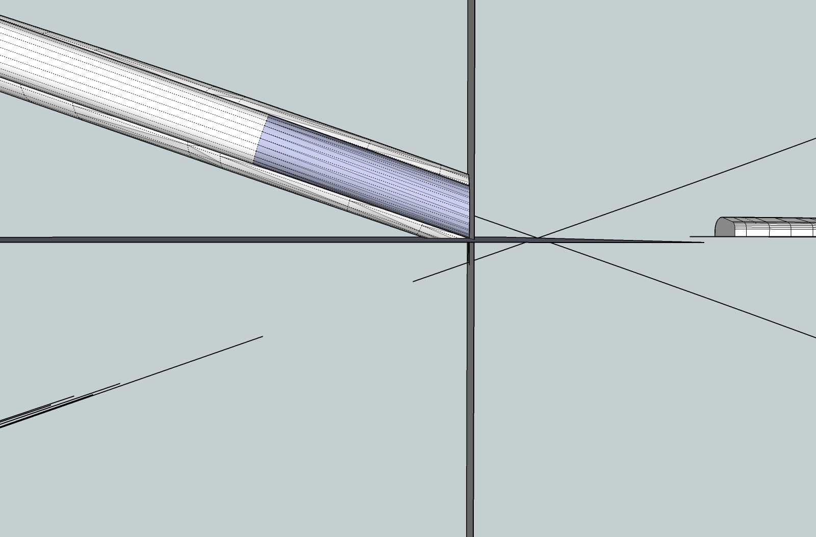
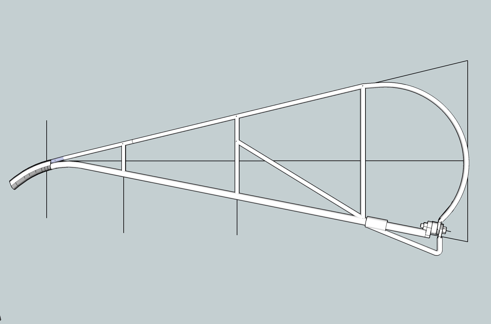
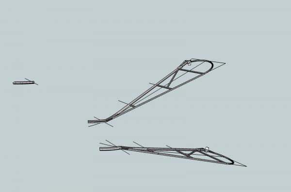
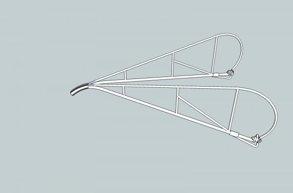
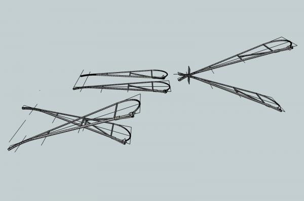
Part 09E Next I copied this frame, and flipped it to get a mirror image. Next I moved them together, for the finished frame sides. I think that next time, I will show how I connect a cylindrical part to a smaller rectangular type part. There are probably better ways, but this is what works for me. That should finish the operations that I think were good to use the frame to illustrate.
-
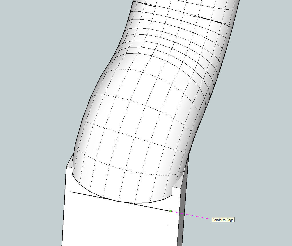
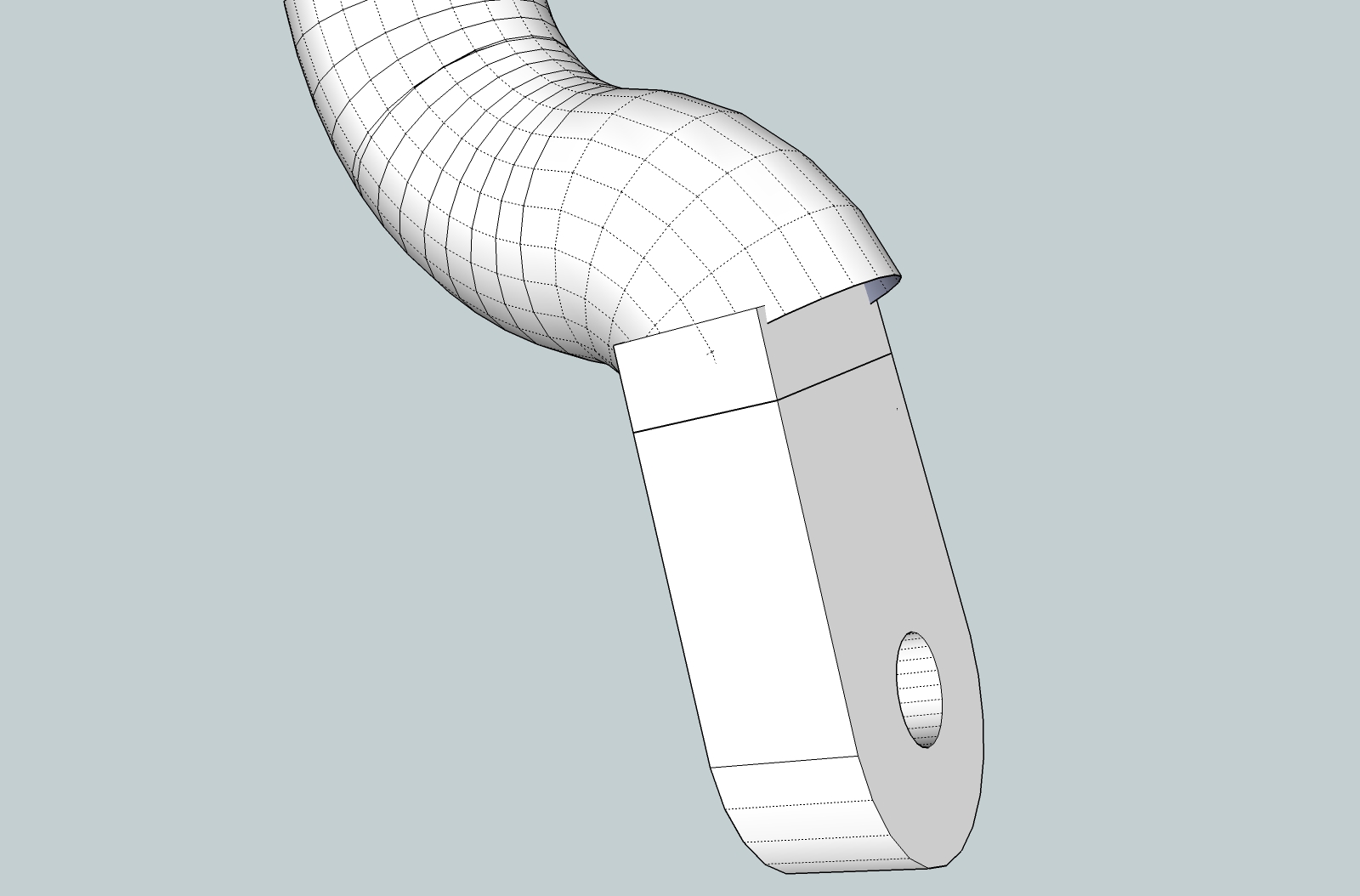
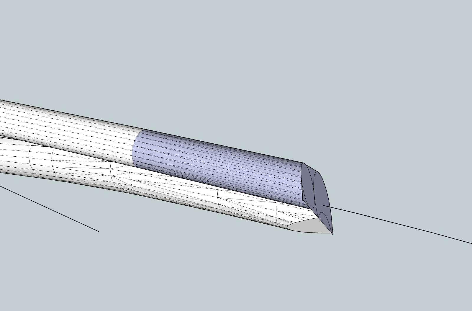
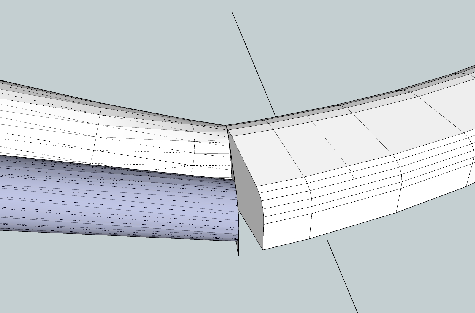
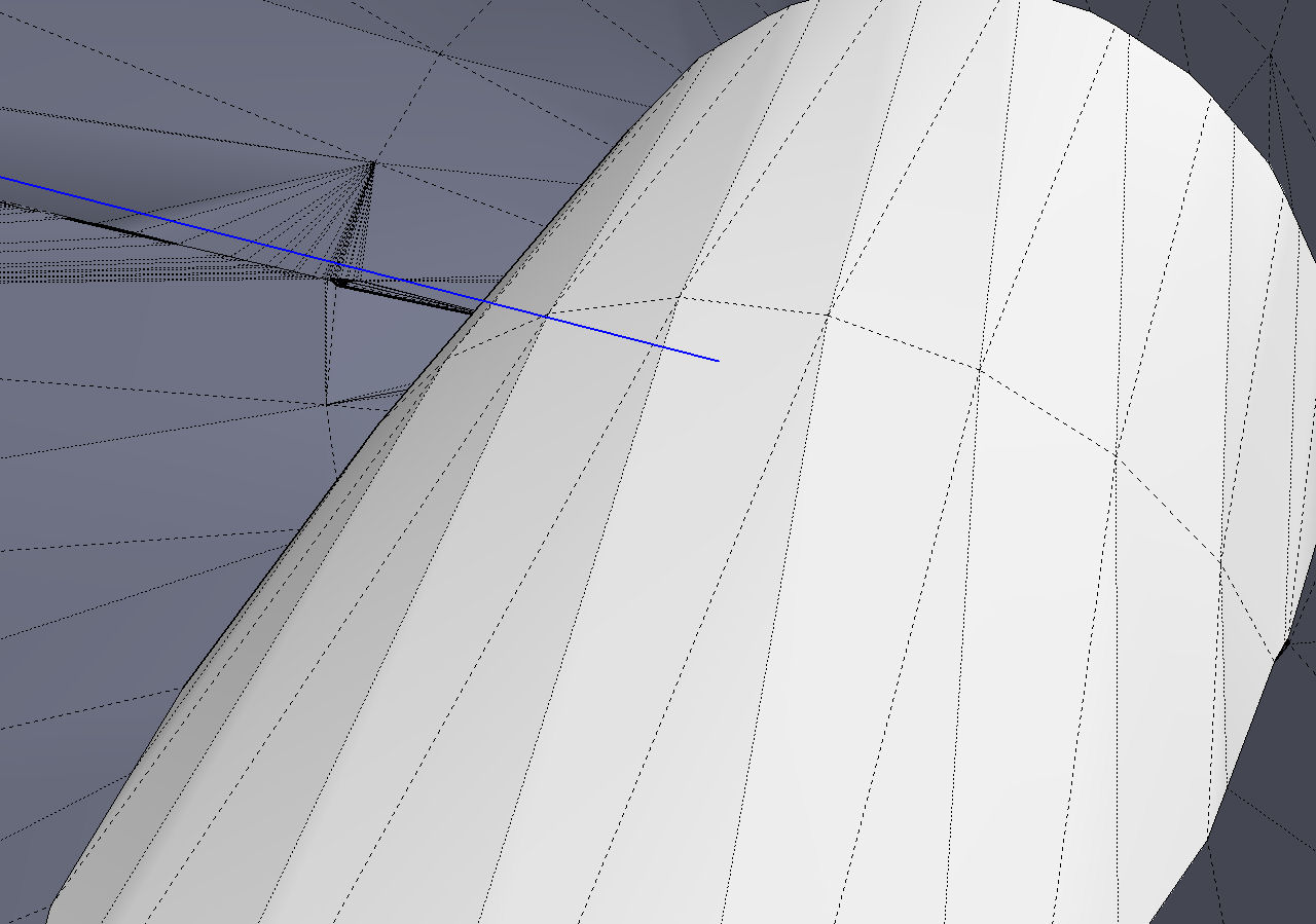
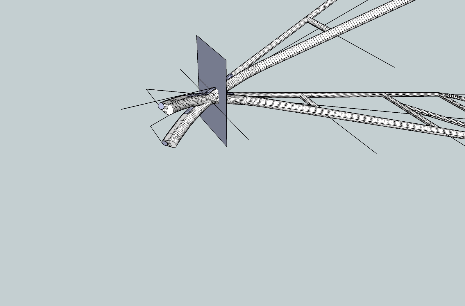
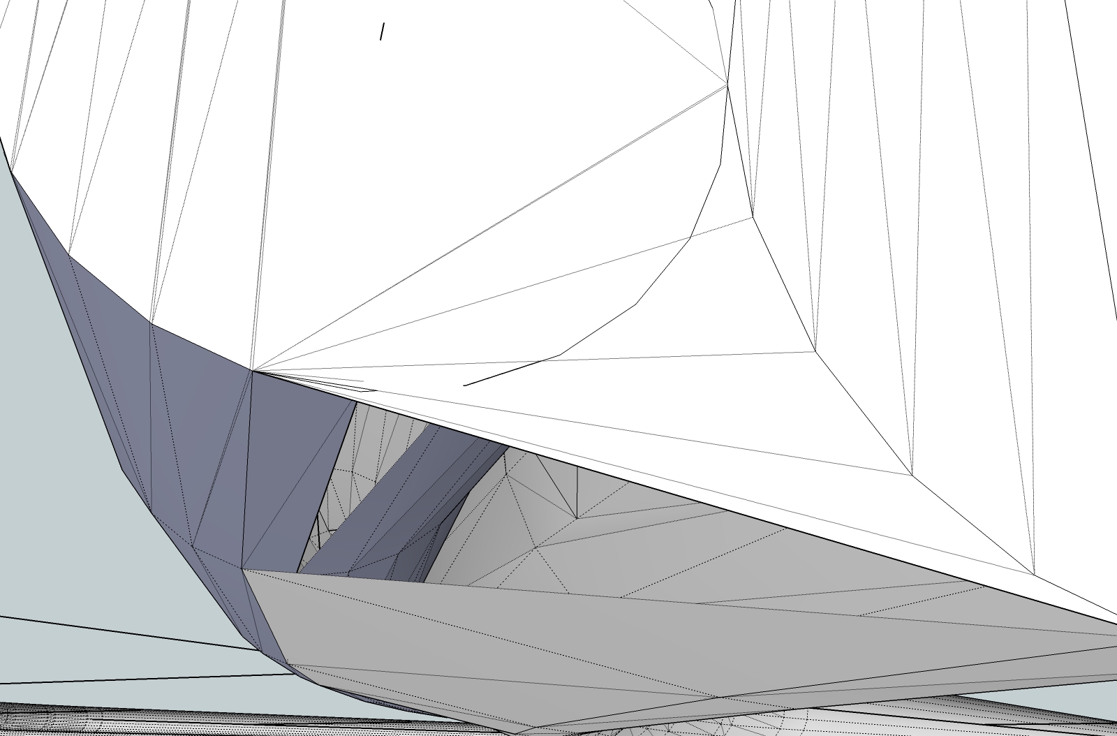
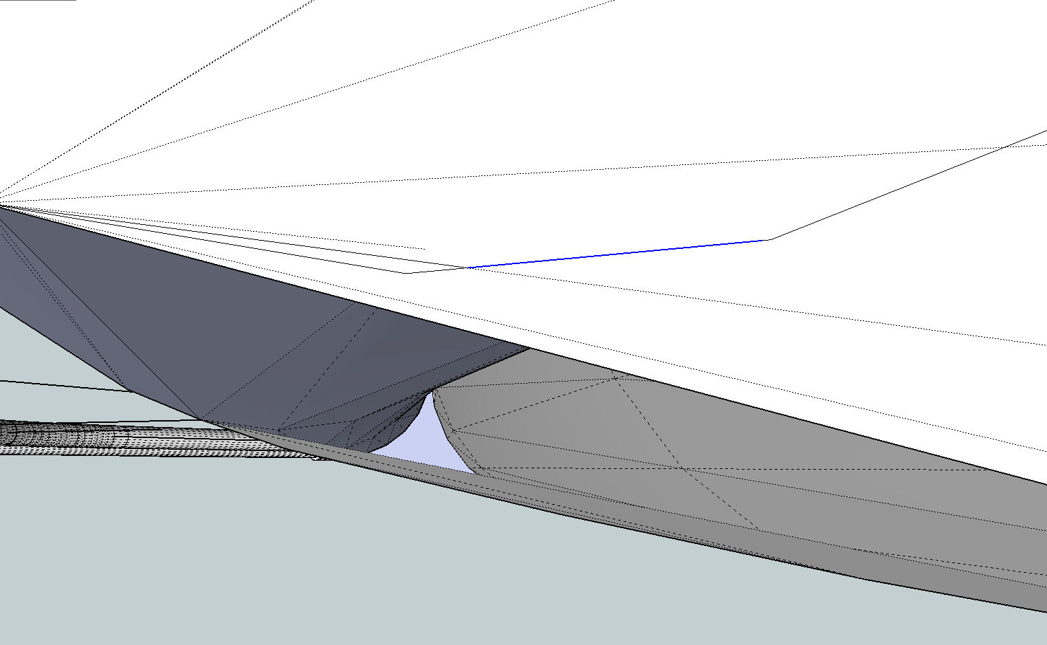
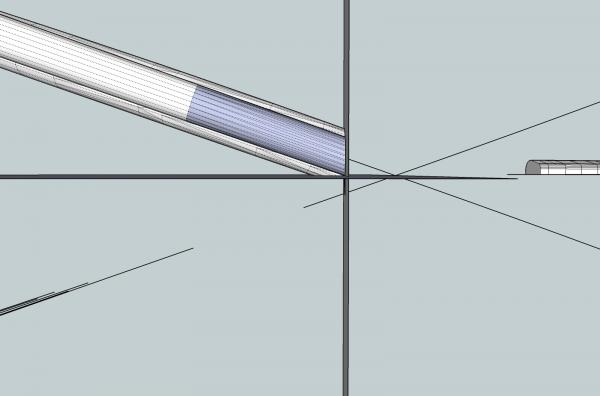
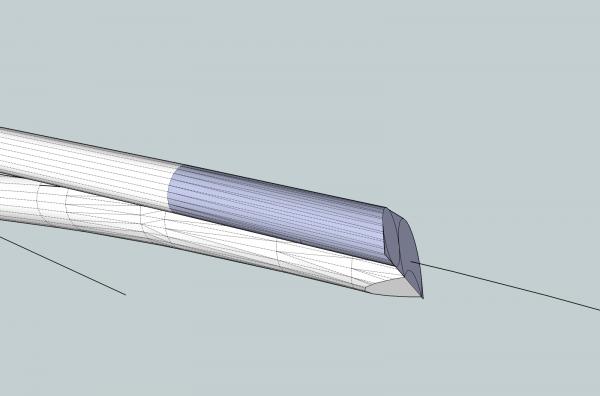
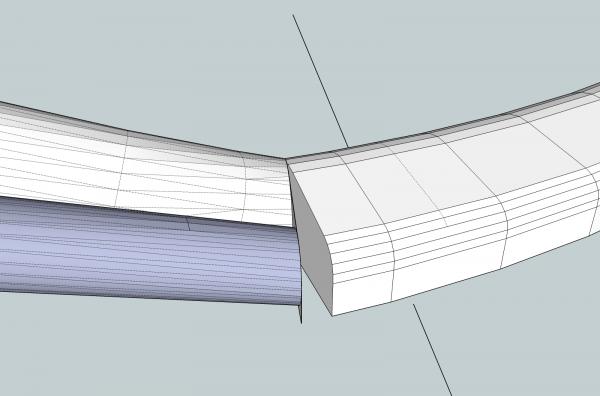
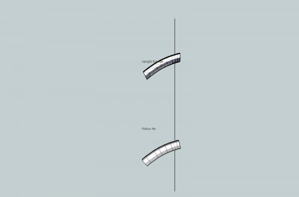
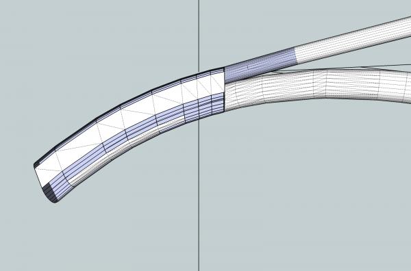
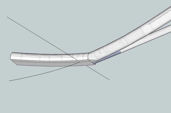
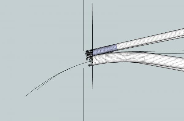
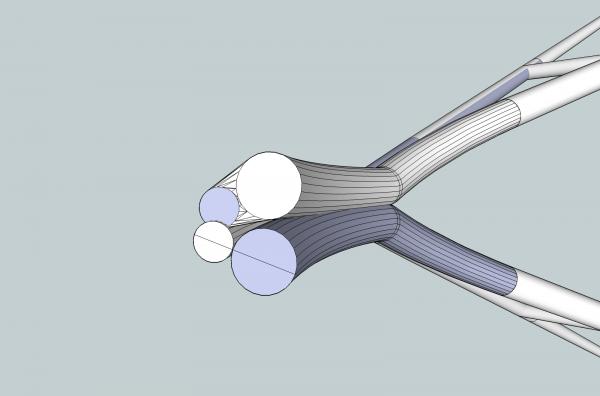
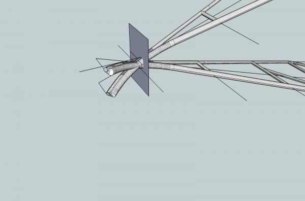
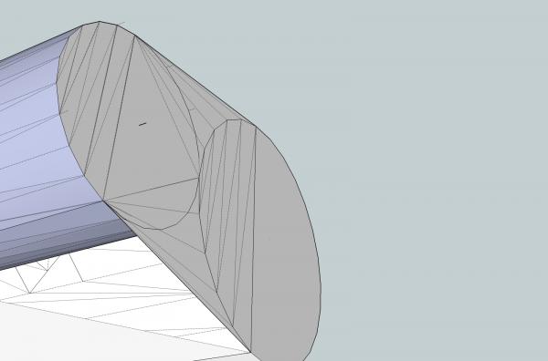
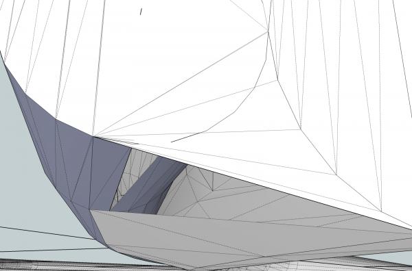
Part 09D Now I need to cut away the second stub of the frame. Because the cylinders of the lower leg of the frame were larger in diameter then the top ones, and I made a cutting plain joint where the upper cylinder met, the lower ones connected further back. I need to preserve this area, for my final frame master part. I used the same method of drawing a rectangle, intersecting the faces, and erasing the unneeded cylinder stub. In the picture below you can see the flat area of the lower cylinder that we need. It is the larger , nearly horizontal curved surface. After cleaning it up and removing the unneeded surfaces, we end up with this, as the end of the frame the new nose will be attached to. Next I made a copy of that good looking Follow Me nose extrusion, and pasted it in place. Wait a minute, what happened!! Remember that Follow Me creates intermediate surfaces that are perpendicular to the path? The surface we started with was not perpendicular to the downward curve of the path, only in the straight. Z axis, direction. So Follow me used the reference surface as the outline of the extrusion, but created a new starting face that was perpendicular to the first line of the downward curving path. It then deleted our original surface, leaving this gap. Looking at the two extruded noses from the side, you can see the difference between them on the right hand end (the area where it will connect to the frame) So despite having missing surfaces, the Upright Extruded nose is the correct one to use, in this case. The Upright Extrude draws all the intermediate faces parallel to the original one. After pasting this nose on the frame, and filling in the missing surfaces, we have this, as the part for one side of the finished frame.

-
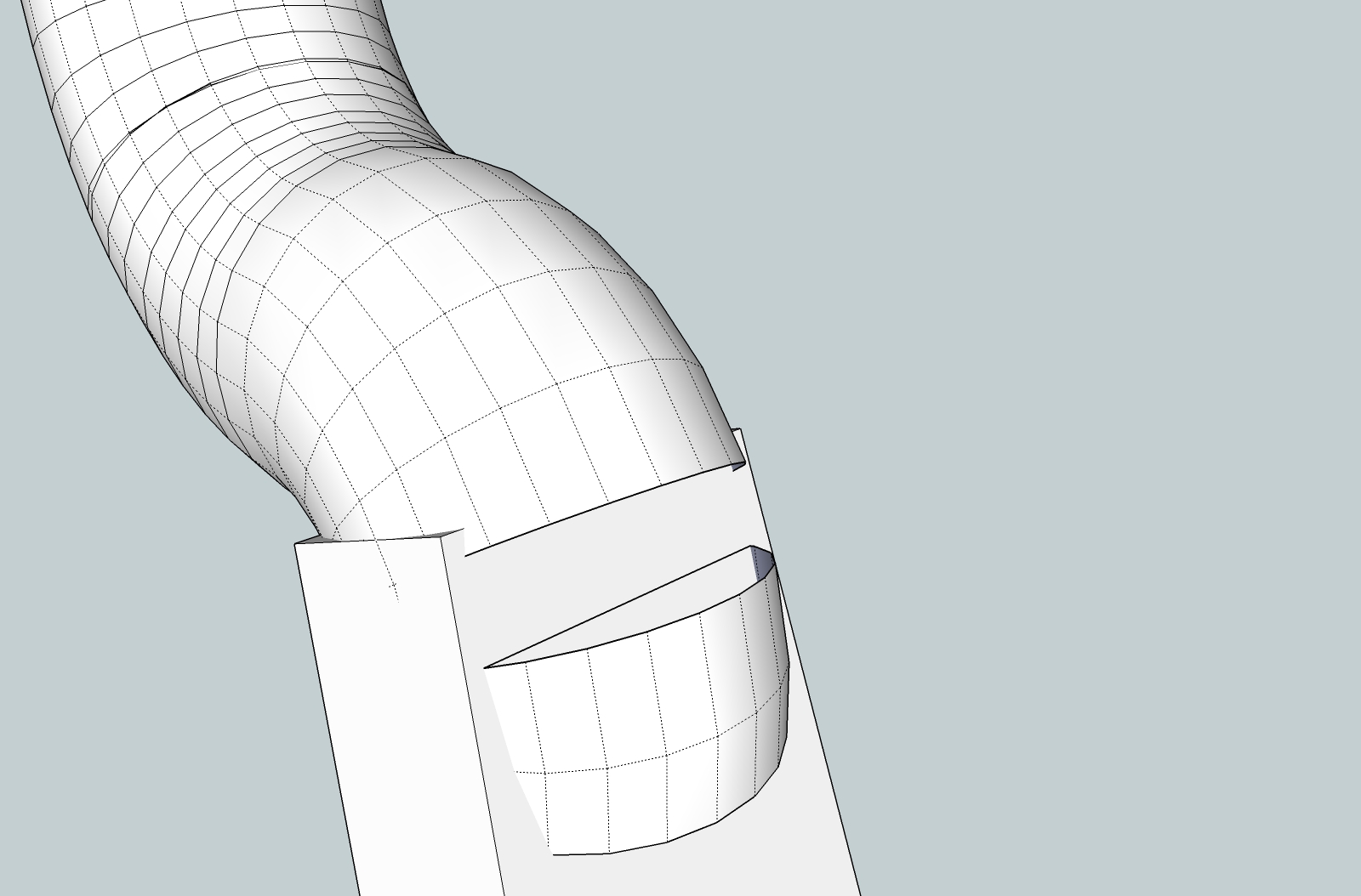
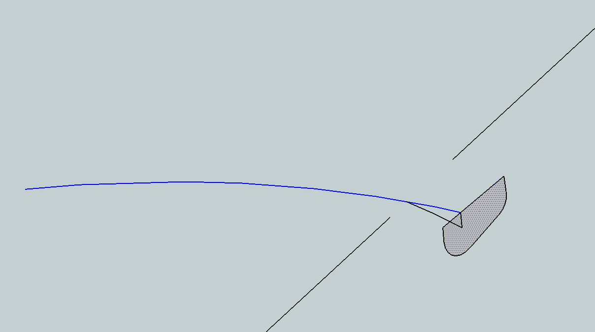
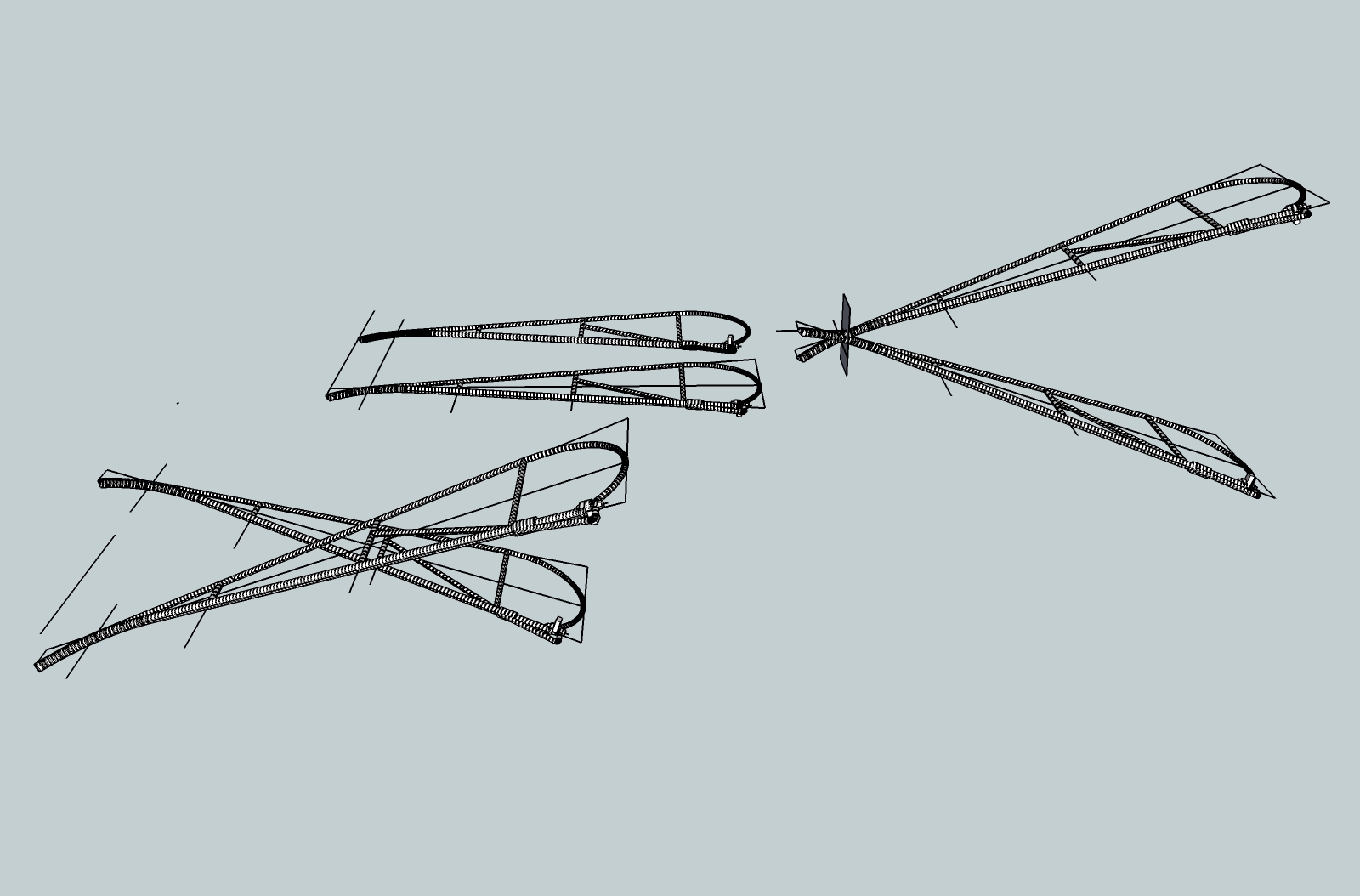
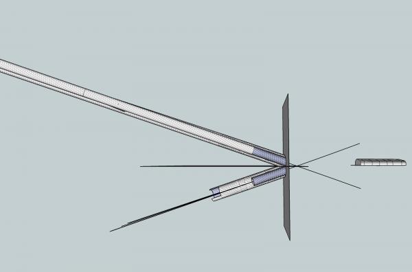
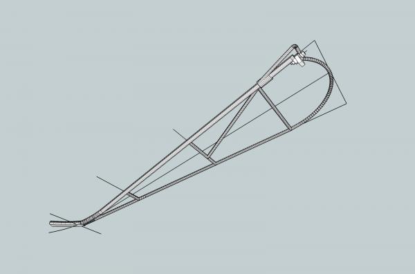
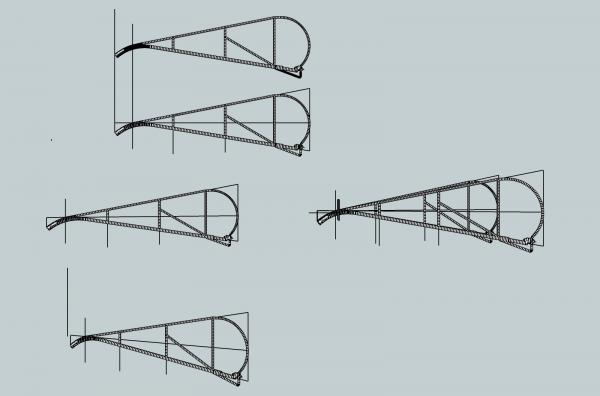
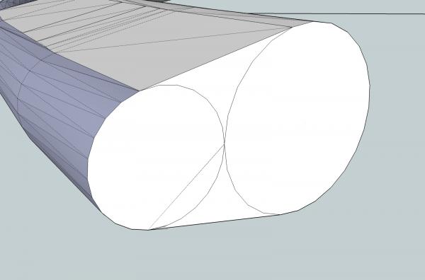
Part 09C With the nose separated from the frame, and the centerlines saved, I erased the nose area. This last area had to be erased line by line, as it was too close to the rectangle, to select them together, and most of them contacted the rectangle, which means that you would have to select the rectangle, and any parts on the other side of it that were inside your selection box needed to capture the whole object, will also select . Finally a clean section to start over with. To save what I had here, I copied the whole frame, and worked on the copy. I will have to delete the rest (back) of the frame, when I finish the nose, so I can paste the nose onto the frame I copied from. This gives me the rectangle, with the cylinder outlines, and the old centerlines, to begin building a new nose. I drew in the straight lines between the circles to represent the eventual sides of the welded area. Sorry I forgot to make a graphic of this step. To get the outline as a single surface, I had to draw over all the lines that made up the outside outline I wanted. SketchUp should have already made this surface a separate one, but for some reason did not. This happens occasionally, and you have to fix it manually. Most likely some very small line was lost during the removal of all the frame parts. Rather than try to find it, redrawing was quicker. I then removed the outside rectangular surface, and the unneeded half of the new nose outline surface. In the above picture, I have also drawn lines connecting the original centerlines, in preparation to draw the line I will use for the extrusion path. I drew from the endpoints along the segments that make up one line to the matching endpoints on the other line. Next I drew a line along the midpoint of each cross line. This gives me a curved line that follows the downward curve of the centerlines, but is straight in the other directions, and perpendicular to the surface I want to extrude. I then erased the extra lines between the old centerlines, the centerline that does not touch the surface, and most of the other one, just leaving the section closest to the surface. I left this line segment to use as a reference point when I paste the nose back onto the rear frame section. The line down the center curves downward in what will be the vertical axis (Y axis), but is straight in the horizontal axis (Z axis). I used the “Shift” key feature of selecting, to select all the line segments of the extrusion path. Then I extruded two new noses, using both Follow Me, and the Upright Extruder. For Follow Me: you select the path, Follow Mw, and then the surface to be extruded. For Upright Extrude: you select the path and the surface, then Upright Extrude. The results from the Follow Me The results from the Upright Extruder. Keep both! The Follow Me extrusion looks like the winner, hands down, but you will see later why I saved both.


-
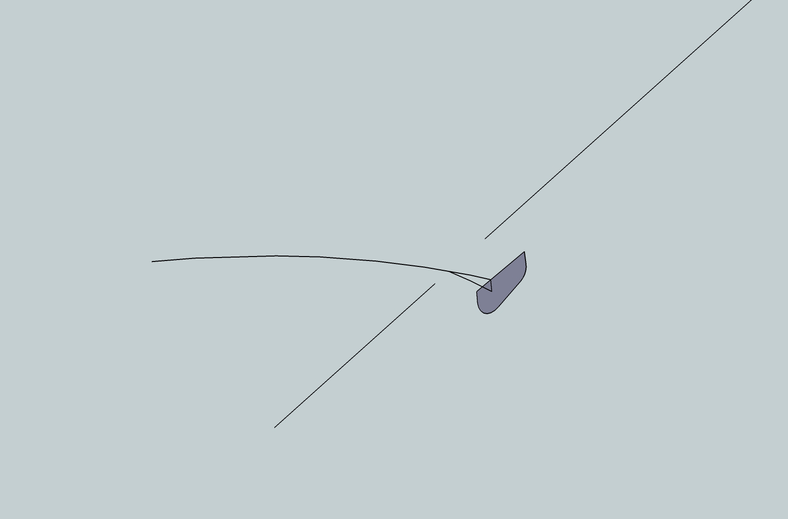
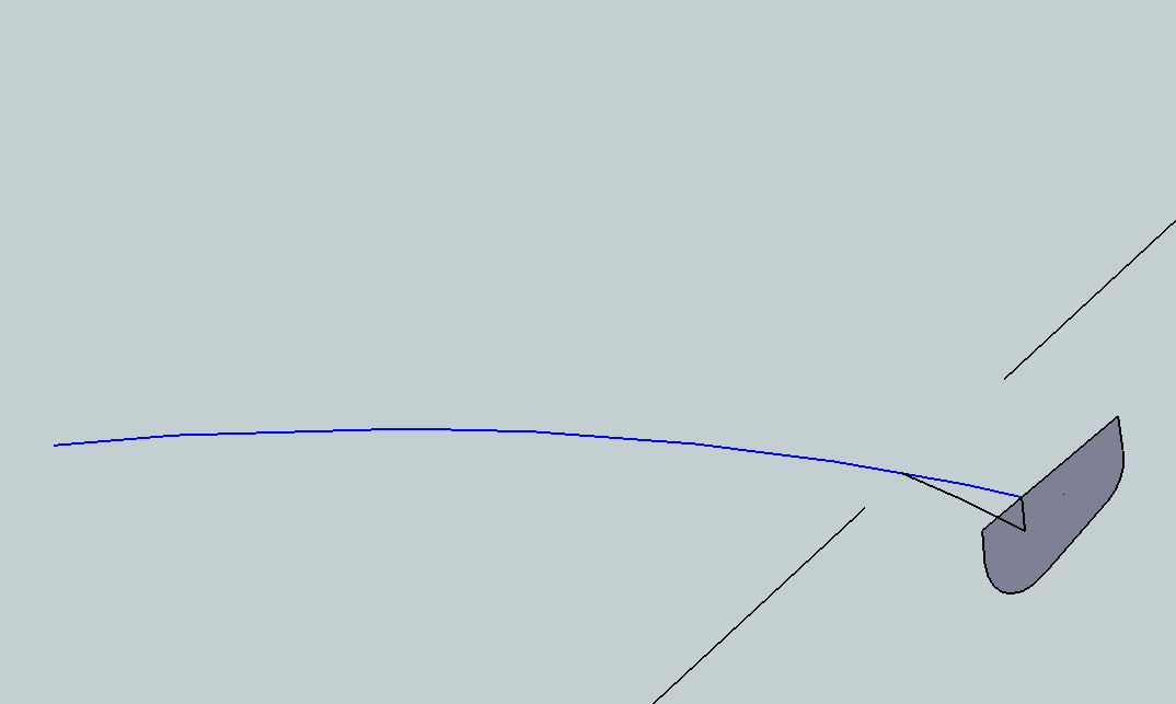
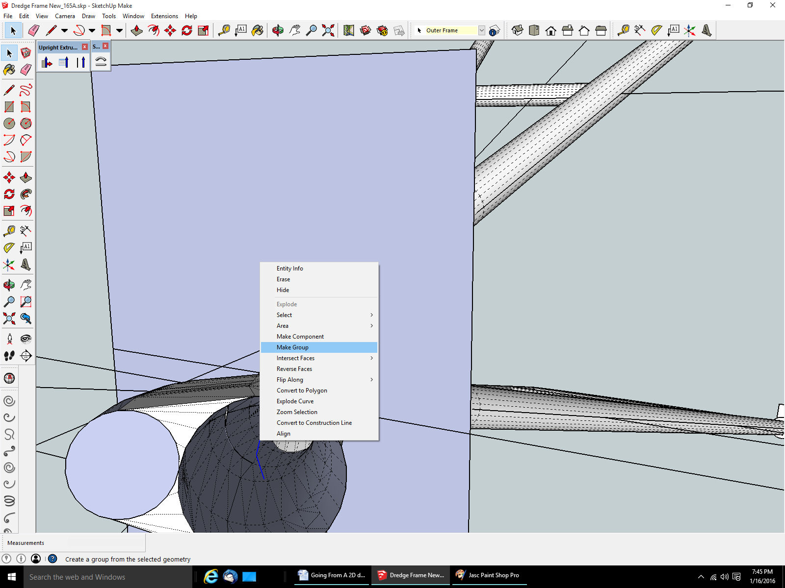
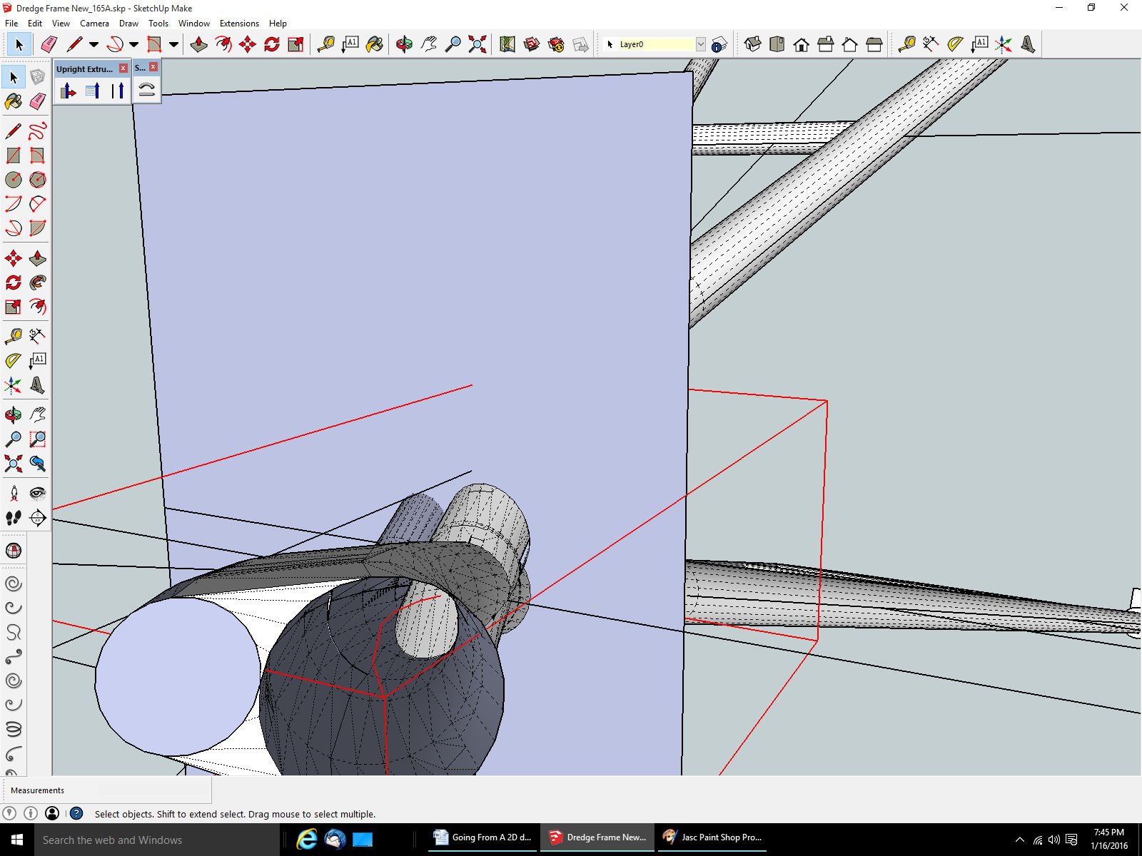
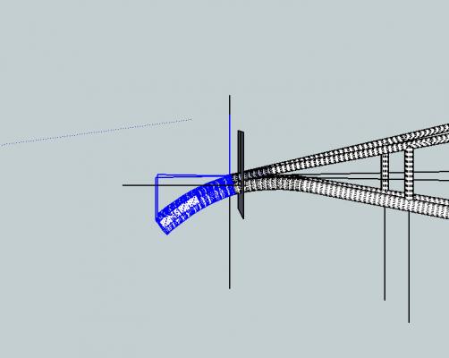
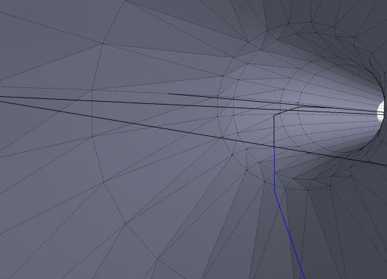
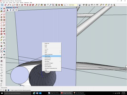
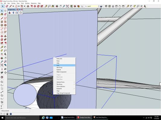
Part 09B I need both the centerlines of the lower rods, to use later to create the extrusion path for my new frame nose tips. To do this, I selected all the line segments that make up the centerline. When you need to select more than one object, you select the first, then hold down the “Shift” key, and continue selecting things, Each new object will be added to the previous ones that were selected. Clicking on one of the already selected objects, will remove it from the group you are building. I erased the end surfaces of these rods, for better viewing while doing the selecting. I selected the centerline, zooming along its length, through intervening surfaces, until I had passed the rectangle surface. I then made them a group, then locked the group from editing. Both operations are accessed by right clicking, while over the object, and selecting the operation from the pop-up menu. The group has been made, shown by the objects being displayed in blue, and the box that shows what overall area the group occupies also in blue. The red Group Box and objects, indicate that that group has been locked from editing. A group can be Unlocked, and returned to individual objects (Explode), using the same pop-up menu.

-
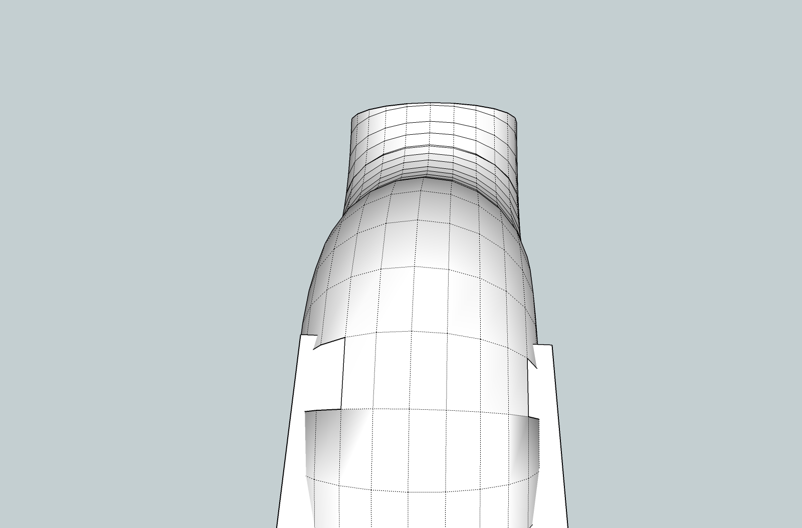
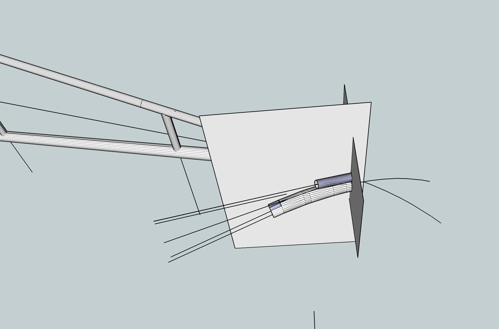
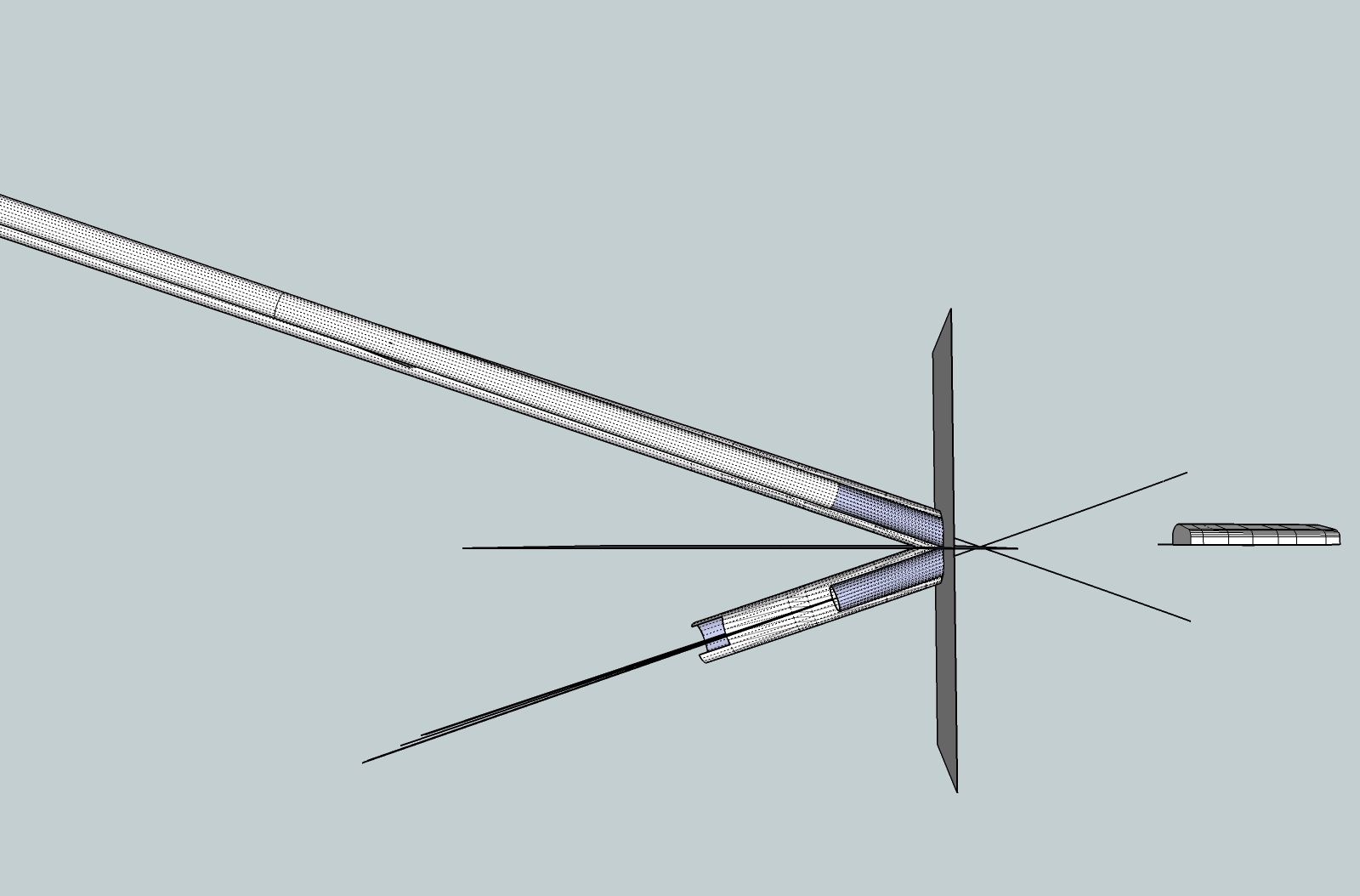
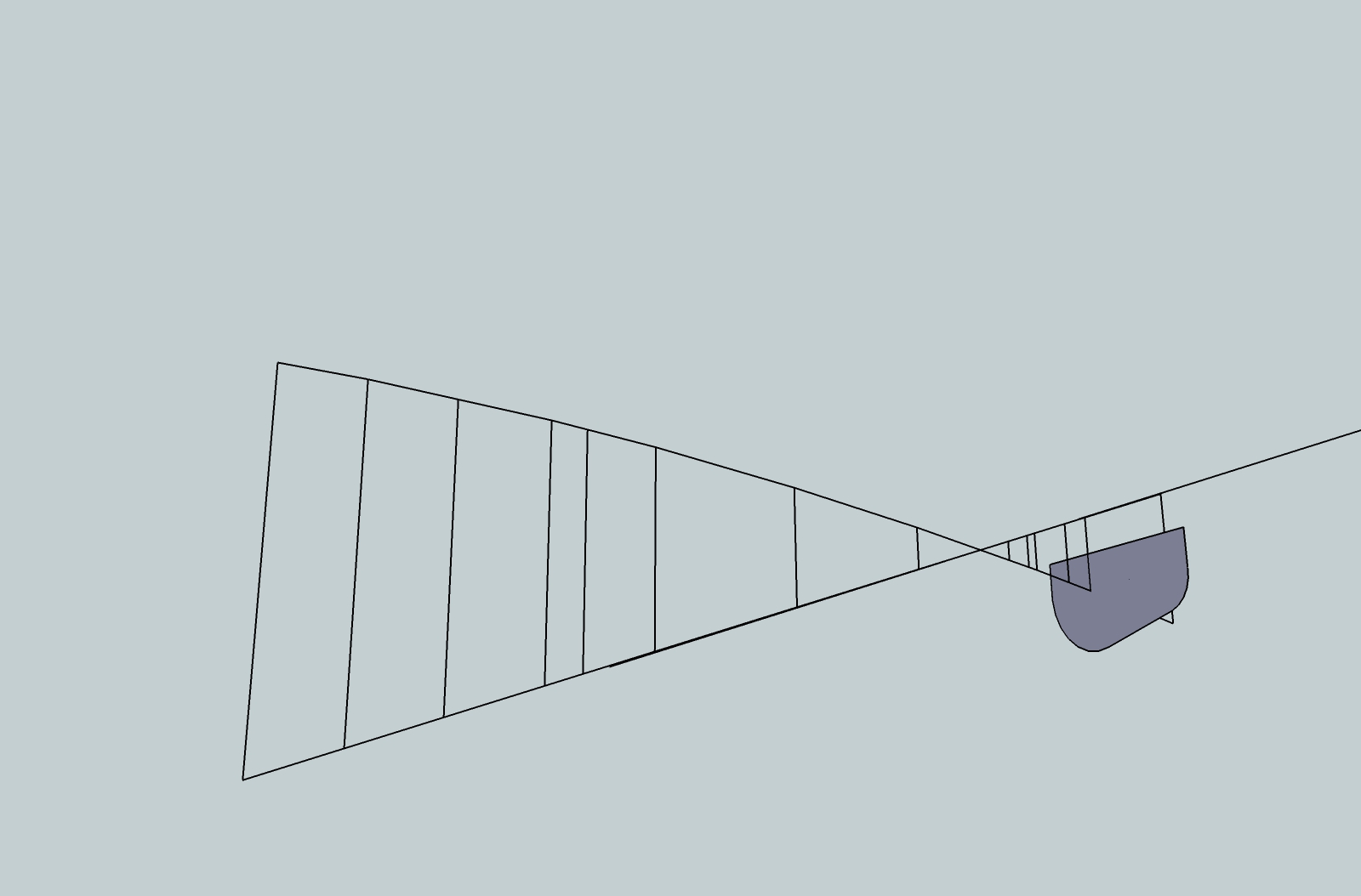
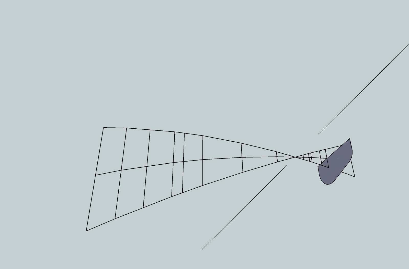
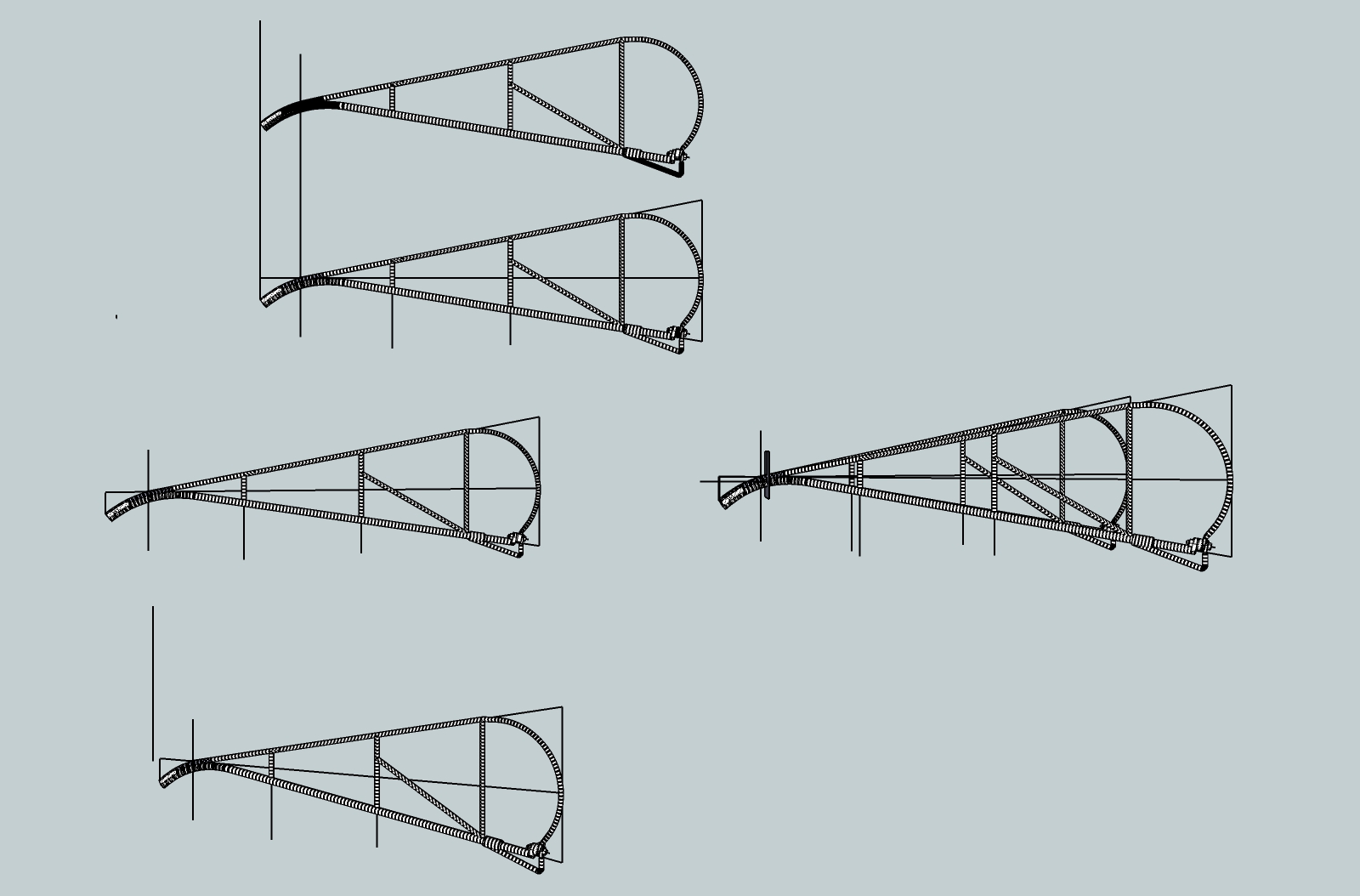
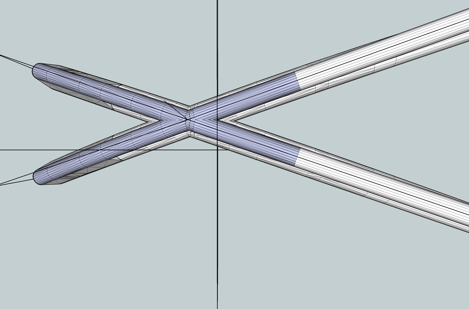
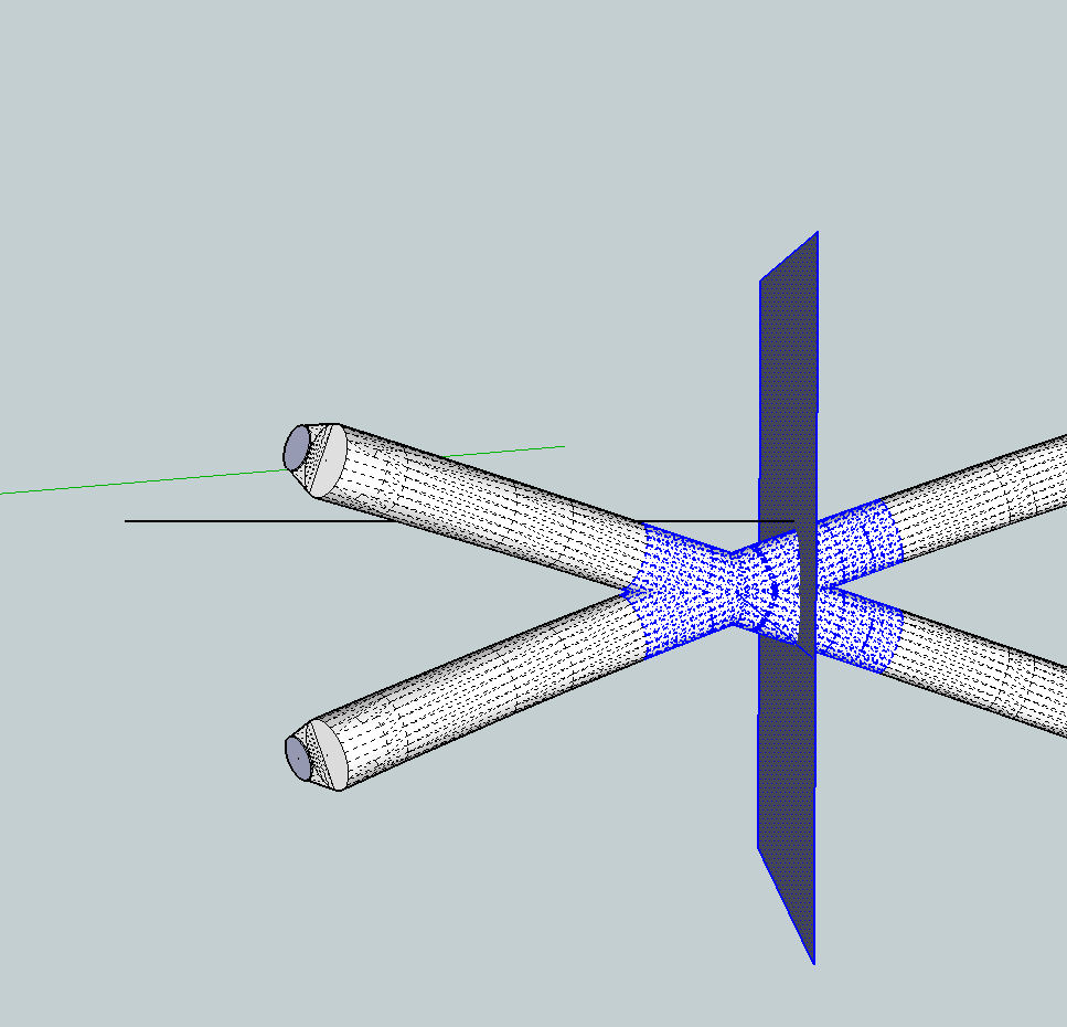
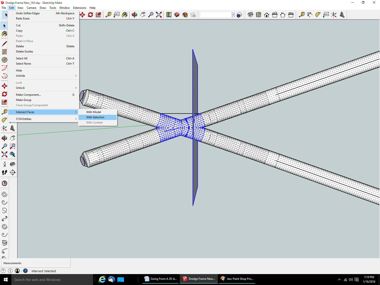
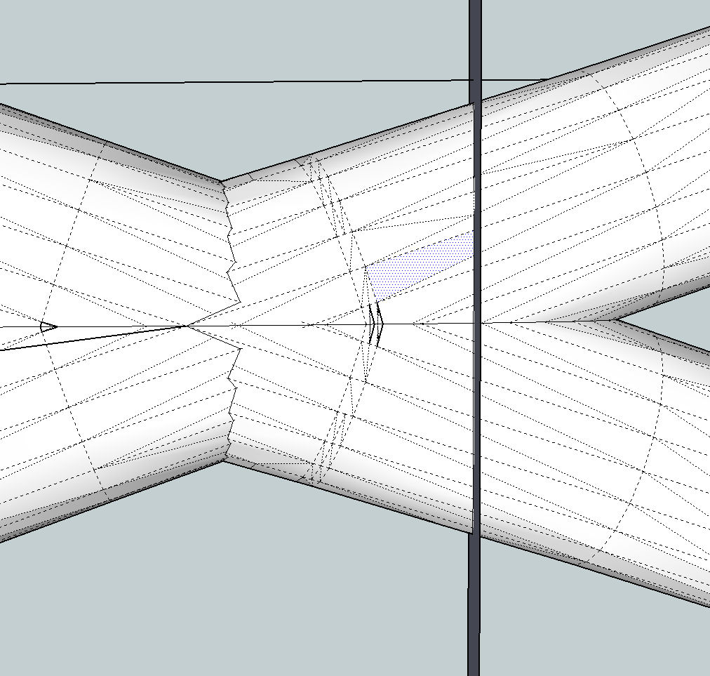
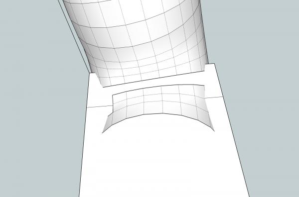
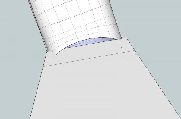
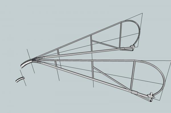
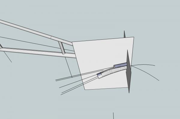
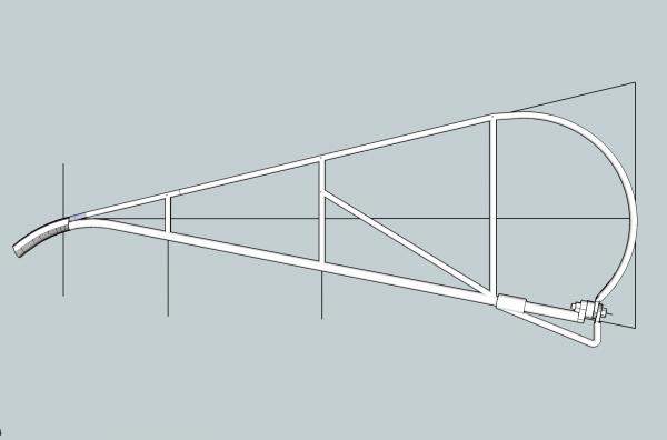
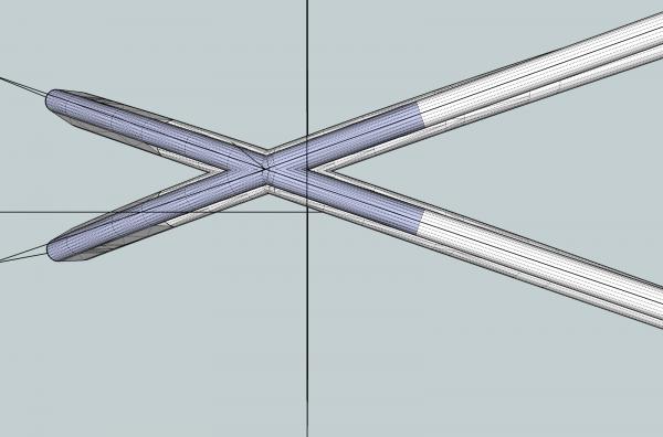
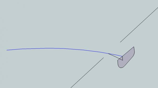
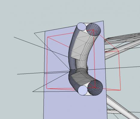
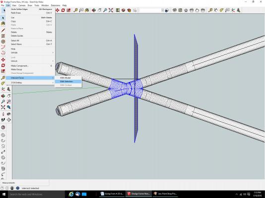
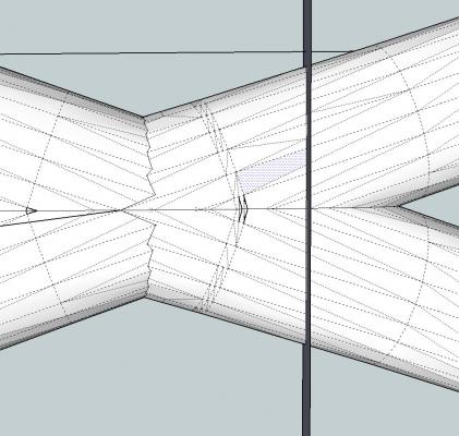
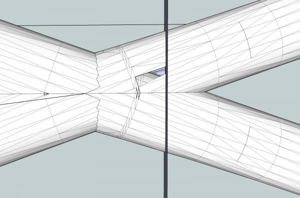
Part 09A Mirroring An Object I have a bone to pick with SketchUp. Most every other program I’ve ever used, has used some form of the word ”Mirror”, in the command to create a mirrored image of an object. Not SketchUp, they use “Flip”, which, to me, means turn over like a pancake, while keeping it the same. Their explanation of “Flip” sounds like they were trying to explain it, and the word Mirror was patented, and they had to avoid it like the plague. Just be aware. Making A New Nose For The Frame I will show all, or at least most, of the steps to create the new nose piece. There are lots of good techniques shown. Because of this it will be a very long post, but bear with me. In the end after writing this section, it has to be posted in 5 parts, A through E Now, last time I told you that I was throwing away all the work I did on the welded nose of the frame, and starting over. When I drew the frames, I started with the main body flat, and angled up the nose. I tried to make the tip curve in one direction, while remaining straight in the other. Well, my geometry calculations were off. When I went to paste the two sides, together, the tips curved away from each other, rather than running alongside. In order to get them to form a mass, they overlapped so much, the nose became only a single frame thickness wide, rather than two. Then it hit me, angle the frames and draw the curve on the flat horizontal surface! So that is what I did. This time instead of two cylinders I made the extrusion one solid piece. To do this I went back to the flat frames I’d started with, before angling the tips, rotated them and combined them, into the proper configuration. I used the straight frame sides, so that I could get the proper flat curve, for the nose. You will see what I mean later. Then I drew in a rectangle where the upper frame leg cylinders just met, to use as the line to cut the tips from the frame. Notice, above, that the larger diameter lower frame leg cylinders connect before the joint on the smaller upper ones. This will come into play later in this process. The upper and lower rods are a single cylinder were the joint will be. I cannot erase the left side on the tip end, without erasing the portion on the right. To solve this I needed to cut the frame cylinders where they meet the rectangle surface. This is what happens if I do not cut the surfaces that cross the rectangle’s surface. There is a function Edit – Intersect Faces. That can be used to do this. When you intersect the faces, all the flat surfaces that cross the rectangle, or any other type of surface you choose, are cut in two, forming two new surfaces. This acts like a saw, cutting through the part. First I selected the area I wanted to work on (including the rectangle). Then I choose the command. Now when I select a surface on the left hand side, it is unique, not part of a surface that spans the “cut”.


-
In Part 27, I said the drawing of the dredge frame showed a tapered point. I was incorrect, what I thought was a tapered point, is in fact the ring. I've corrected the post.
-
Most times it's not that bad. I had to create some graphics for the posts, and in this case, just deleted a section, to use as an example. If it had not been as fiddley as it turned out to be, you would have gotten as intense an example. It just happened to come out like that, so I went with it. It turned out to have quite a lot of good operations to be done.
-
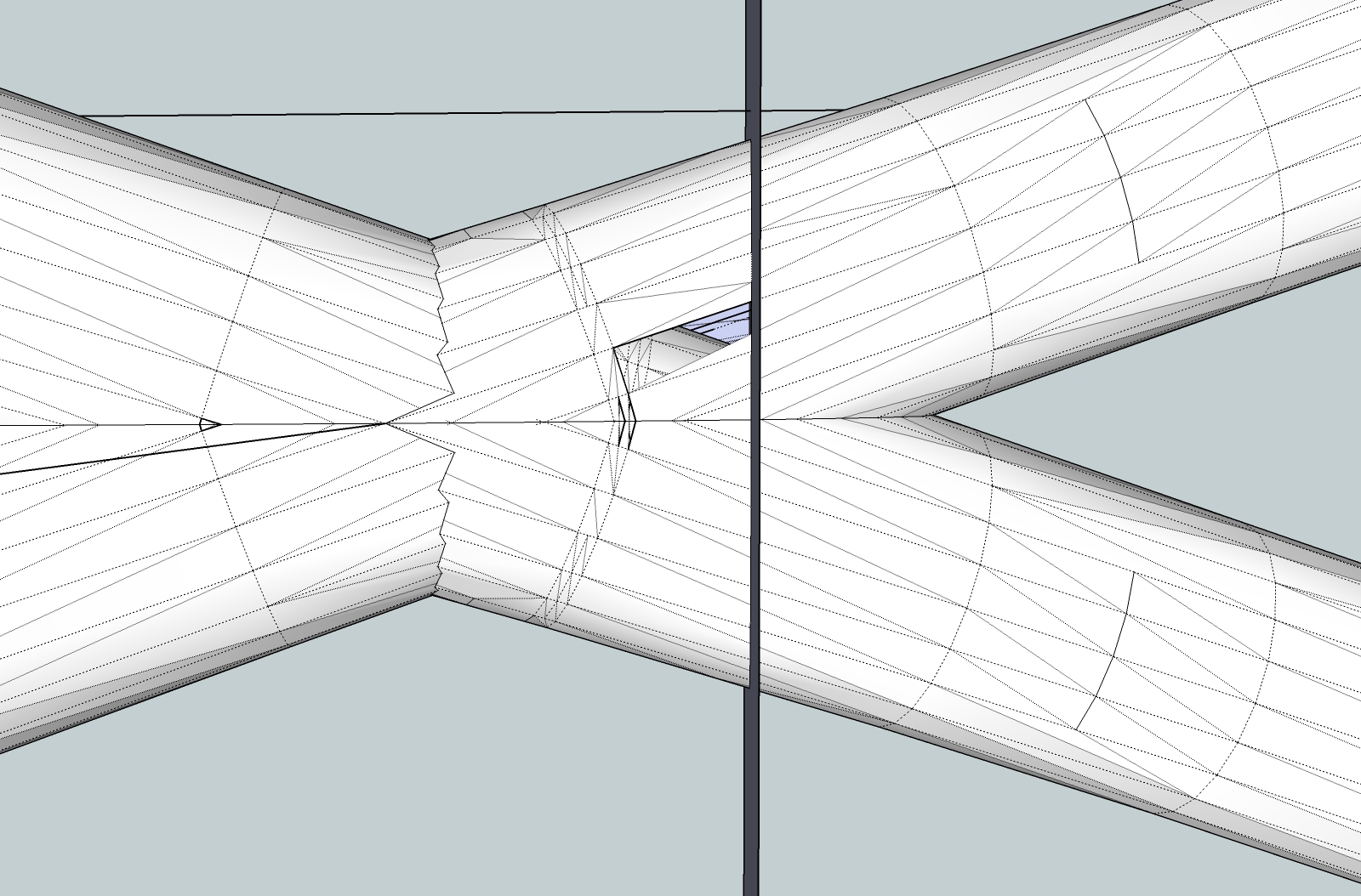
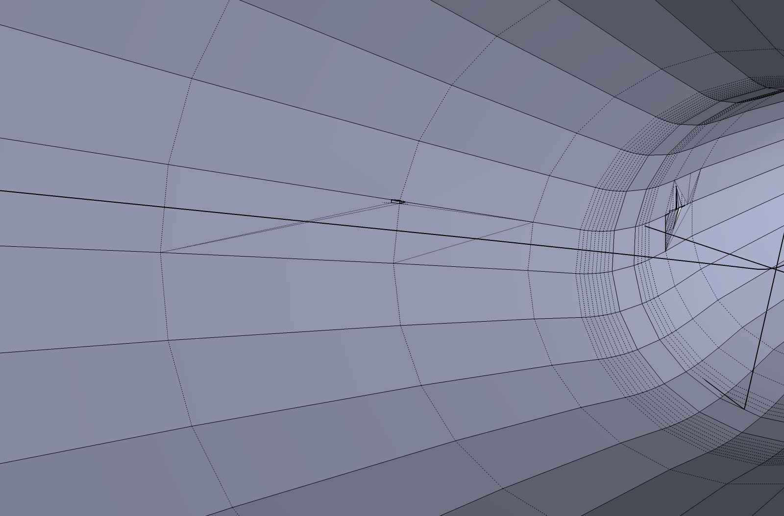
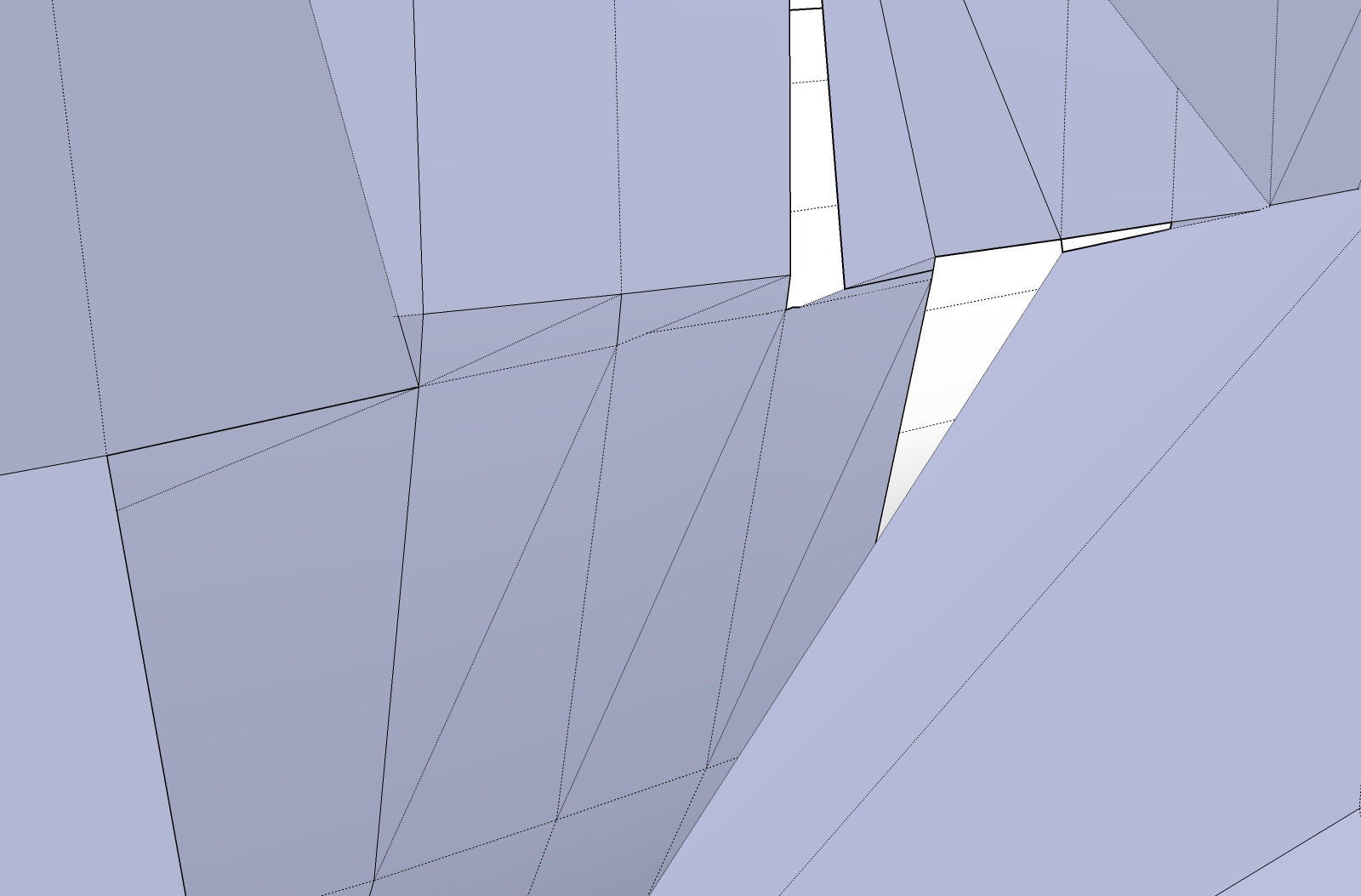
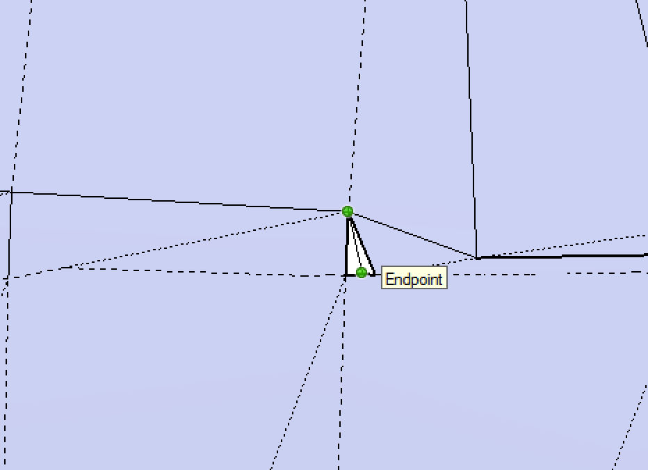
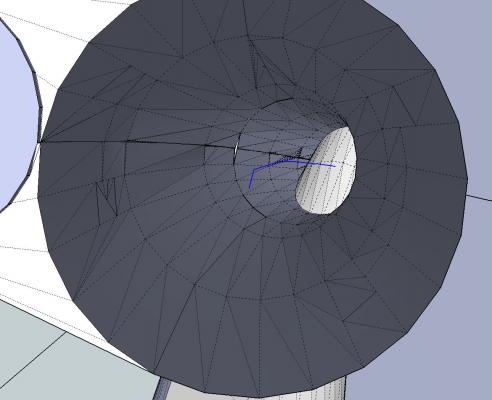
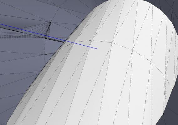
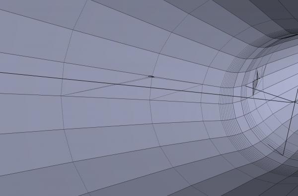
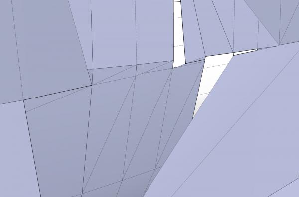
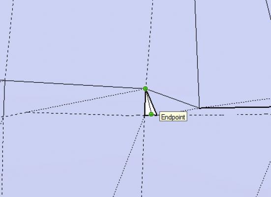
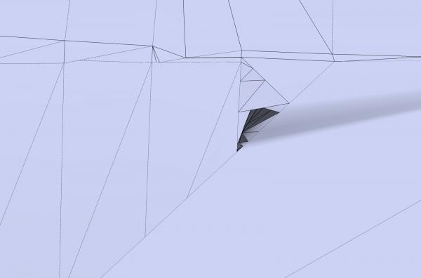
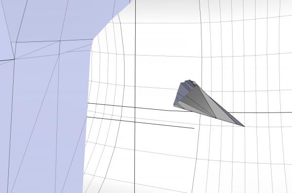
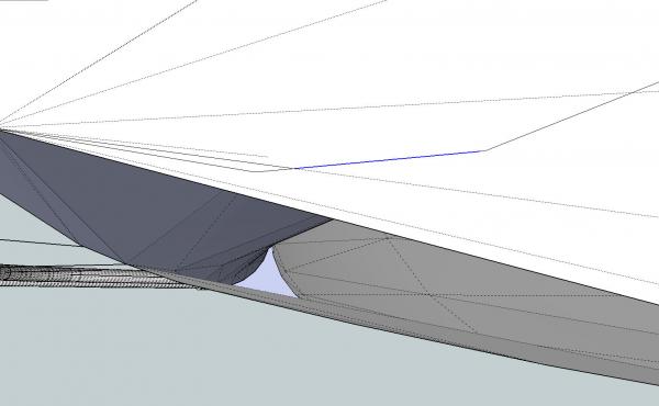
Part 08B You also have to check for missing surfaces, at junctions of shapes. The pictures below, are the interior of one of the cylinders. I zoomed through the end wall and scrolled along its length, checking for problems. And found some. I managed to fix most of them, until I got to the bottom of the large lower triangular area. When I was filling this area, from the angle I was looking at (a view I could not get back after finding the problem), it looked like the area was closed properly. When I panned away, however, I saw that I had messed up. Instead of a flat surface, I had created a pocket by connecting to a lower surface, that looked like it was flush, at that viewing angle. I deleted this and by changing the view, I was able to connect to the right lines. Sometimes the endpoints are not terribly visible. In the picture below, that endpoint at the base of the triangle, was only shown when I ran the cursor along the bottom line. In the next part, I’ll explain why I threw all this careful work away, and used a different method to simulate the welded front of the dredge. This is why I save to new file name versions frequently (Dredge Frame _45, Dredge Frame_46, etc.), as I talked about in a previous part.
-
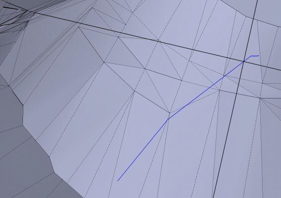
Part 08A Some times when you go to fill in a space or missing section, you cannot see all the endpoints. They may be very near one another, so that you cannot distinguish between them, or otherwise hidden. Sometimes SketchUp should fill, but does not. When this happens, you have to resort to creating many triangles, sometimes to minute proportions. I will use the example from the last post, but intentionally make a mistake that forces me to use this method. Here I’ve drawn the upper line to an edge rather than the endpoint. This creates the situation I talked about. I will ignore the endpoint that I should have connected to. I continue to draw in triangles. I generally try to use a go from one corner, to the midpoint of the other line for the second end of the line. When I drew that last line to the right (see below), SketchUp filled in the rest of the space (see below). This happen often, and you can just be thankful that you are done. Don’t look a gift horse in the mouth. The last line drawn. The highlighted area, is what SketchUp finished filling in, when the line was drawn. Remember from the last post that the ends of the cylinders in the example, did not line up. So all the lines here enclose surfaces that differ in orientation, and cannot be deleted, without also deleting some of the surfaces. However if they had formed surfaces that are in line (entire surface should all be one flat plain), you can delete the extra lines, to clarify the drawing. To show you this, I will use example from the first two pictures of Part 7, where the ends did line up, and the entire end should be a flat surface. We can erase most of these lines. But, be careful. Not all the lines can be erased! The lines that form the circular rim of the cylinders cannot be erased, without losing the adjoining cylinder surface. If I delete the highlighted line above, I will delete a surface, on the cylinder. This is the end with most of the lines removed. Even here I had to leave the line (actually 2 lines very close together) inside the left cylinder end, or the upper or lower surface was also deleted. Check frequently!


-
Thank you for the suggestion.