thibaultron
-
Posts
2,952 -
Joined
-
Last visited
Content Type
Profiles
Forums
Gallery
Events
Everything posted by thibaultron
-
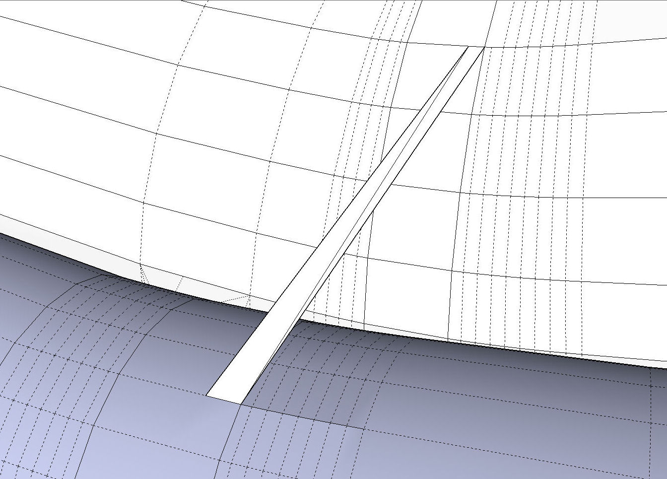
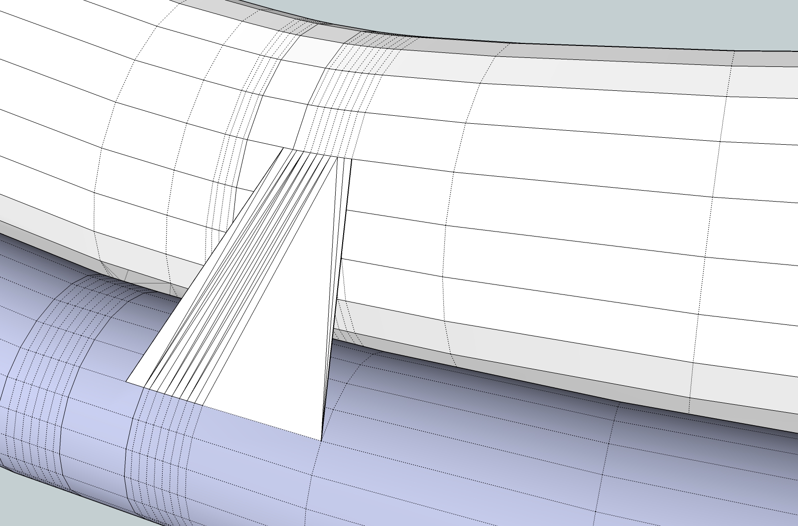
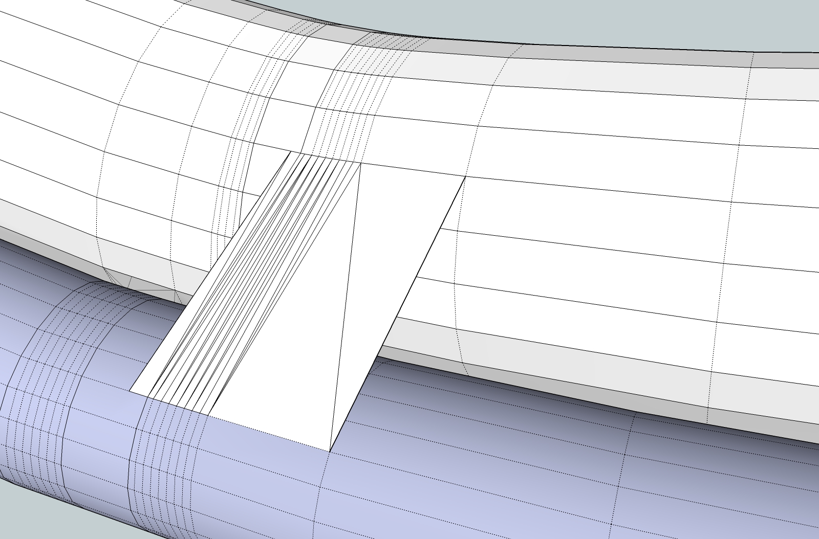
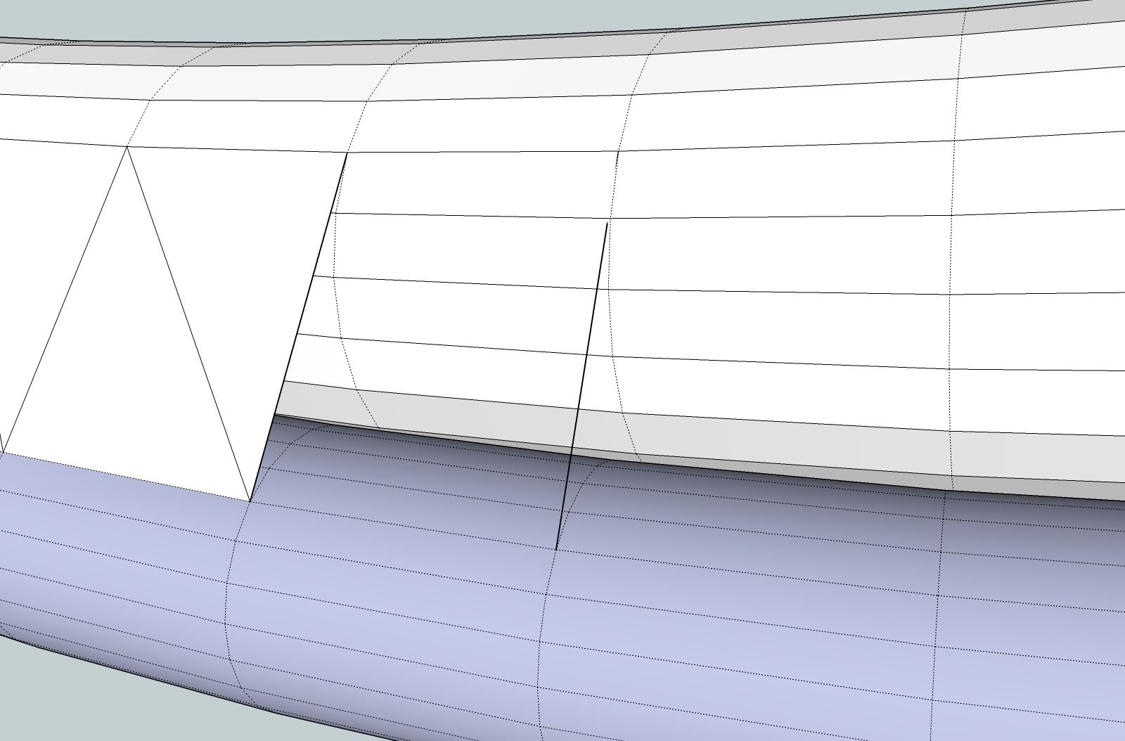
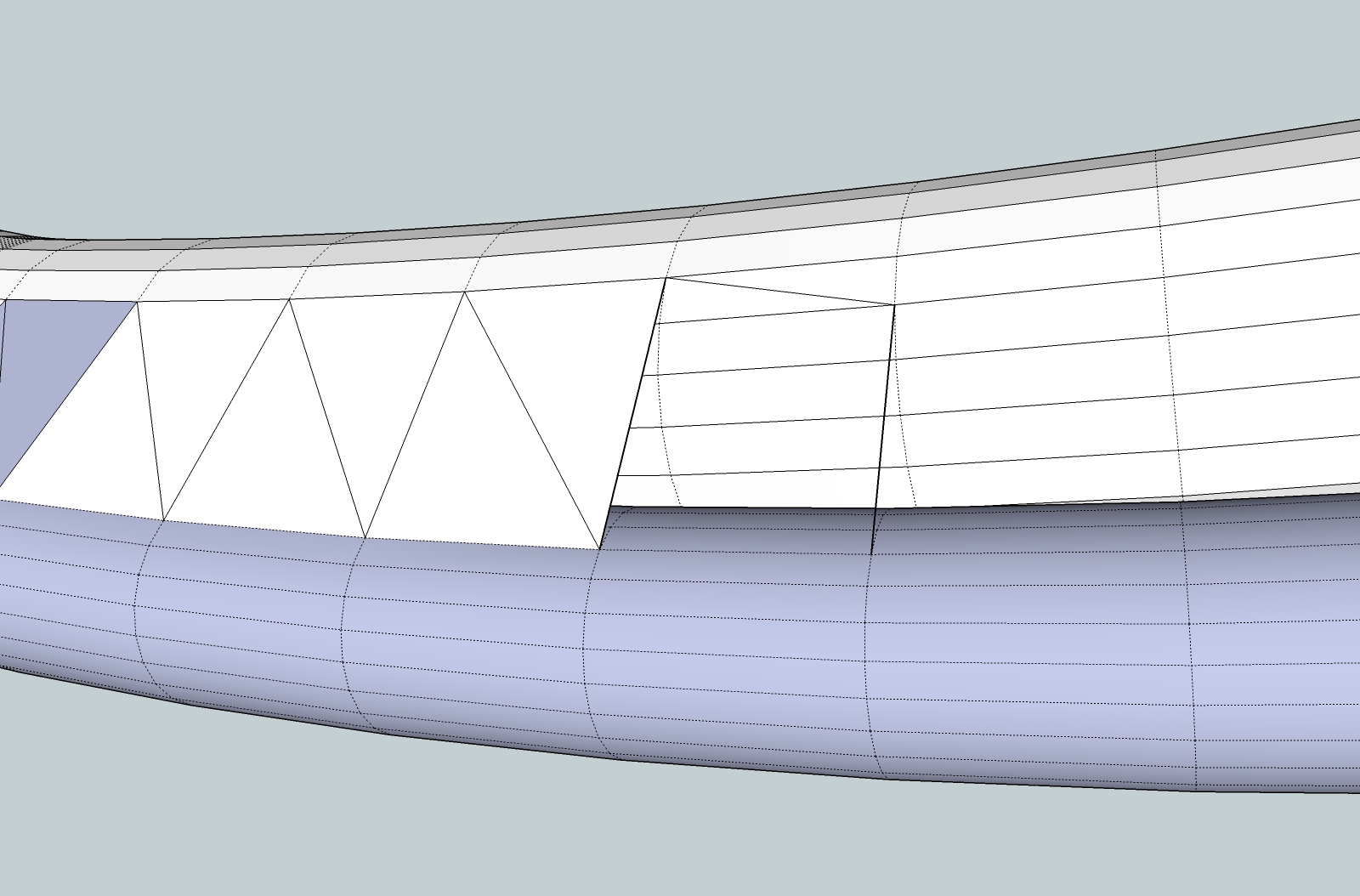
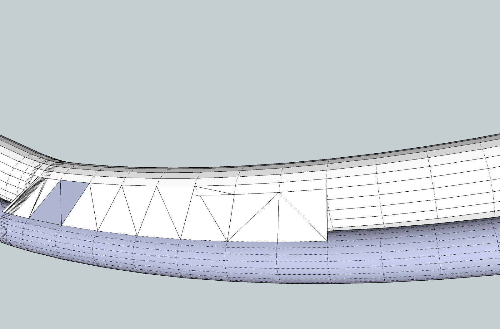
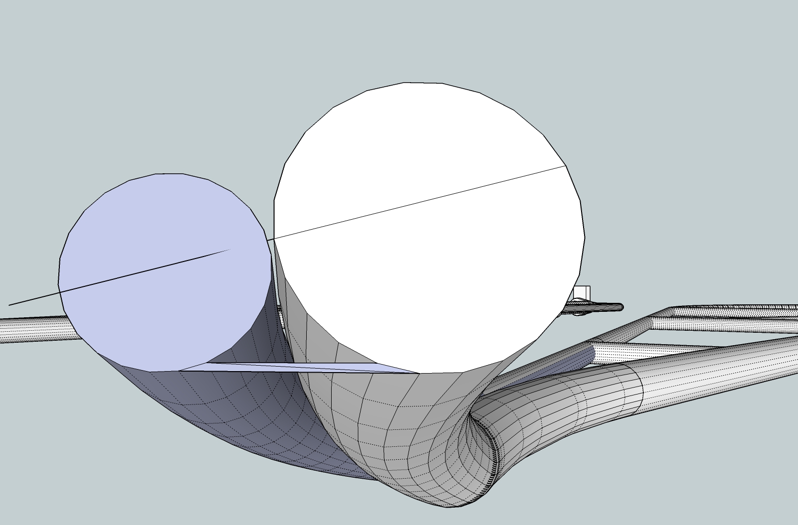
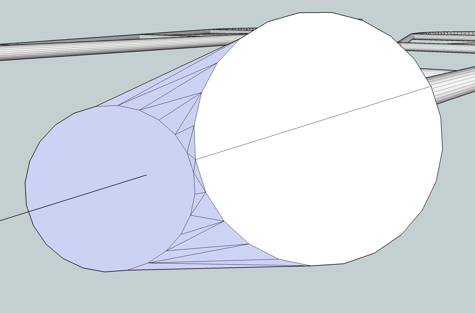
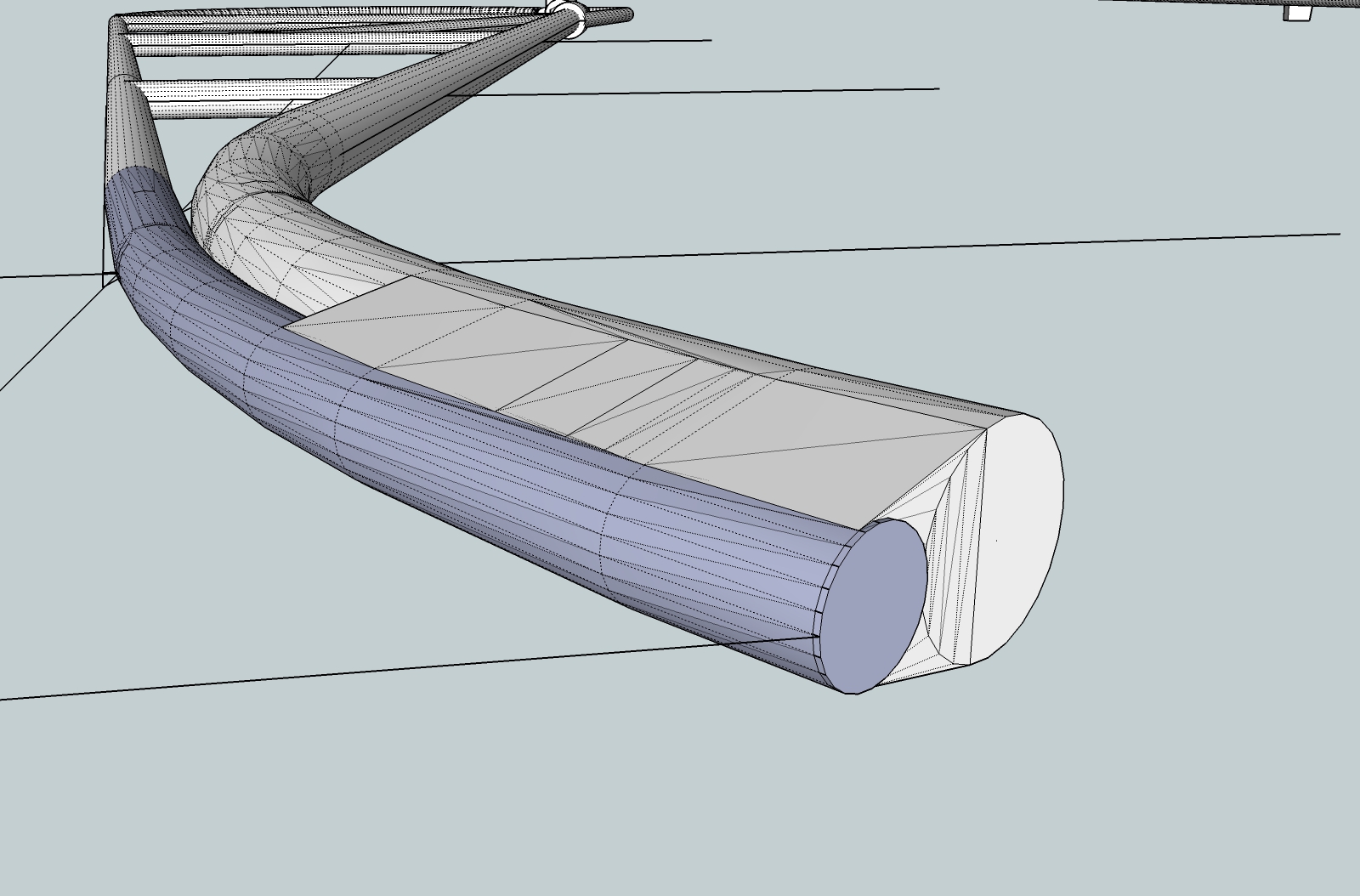
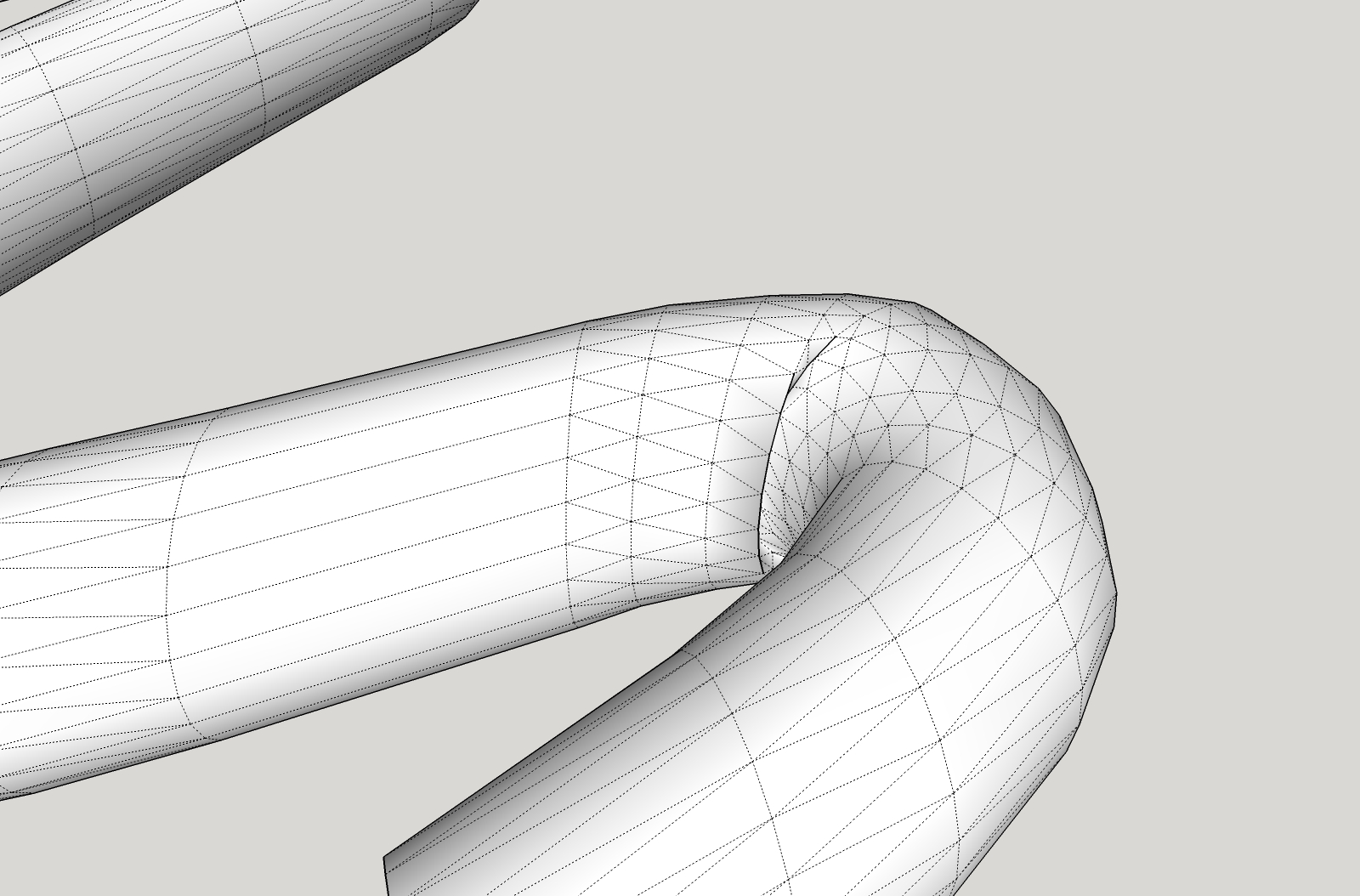
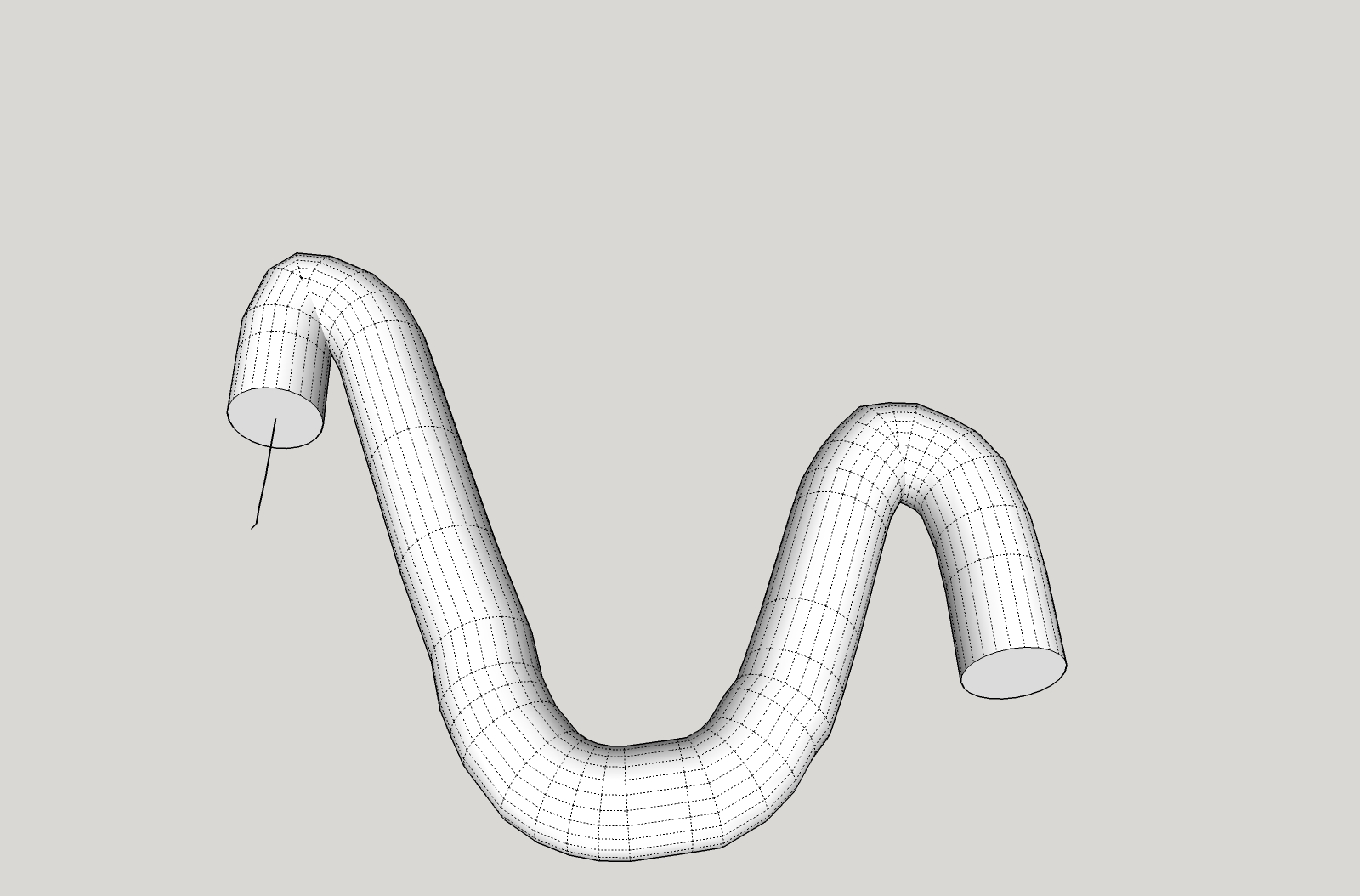
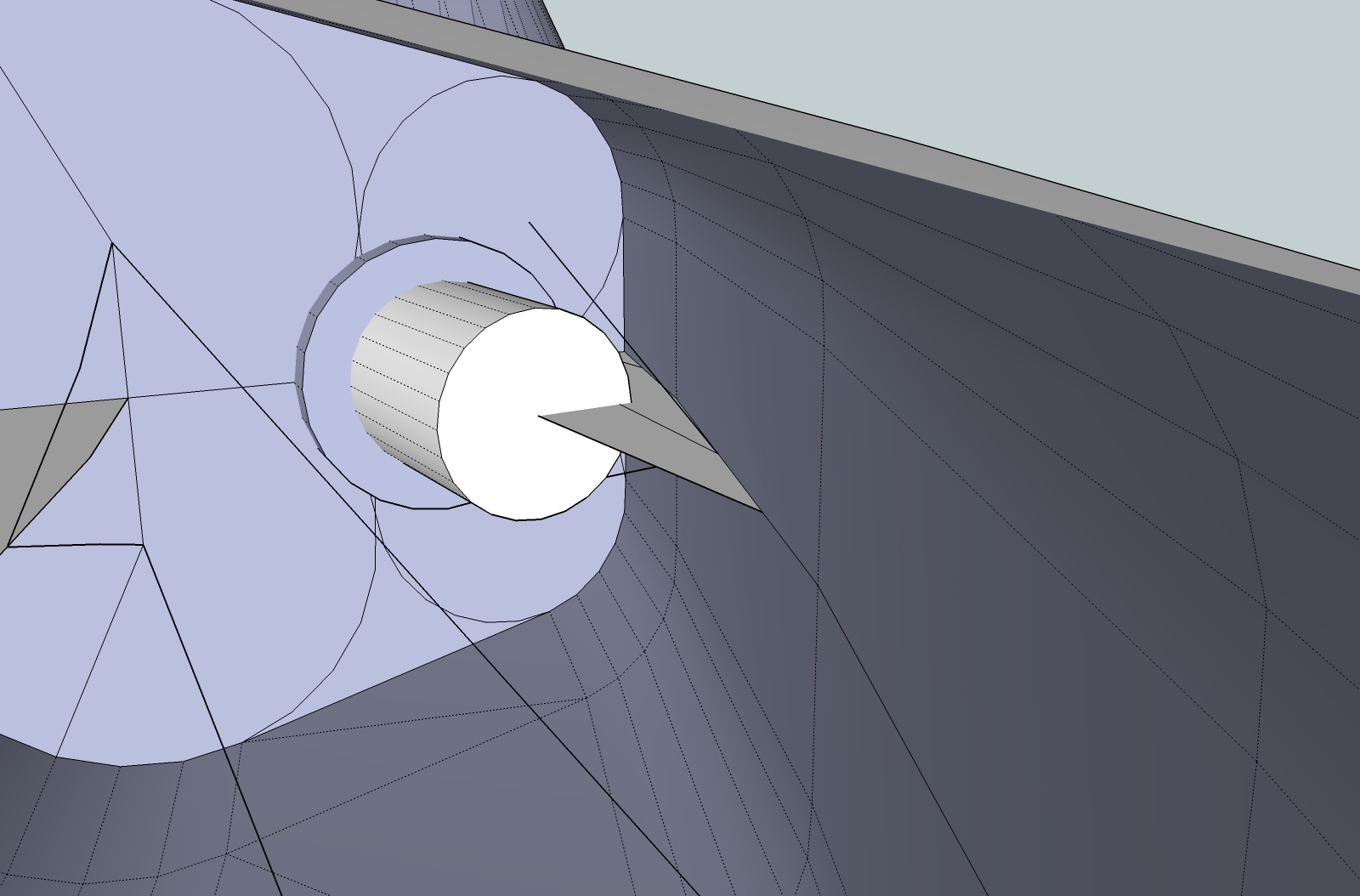
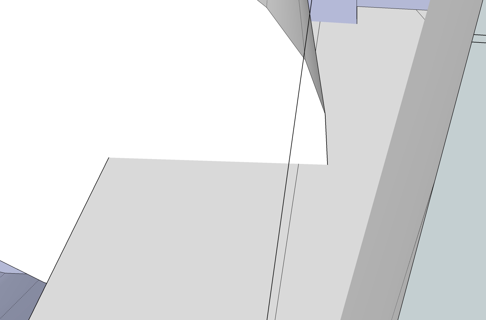
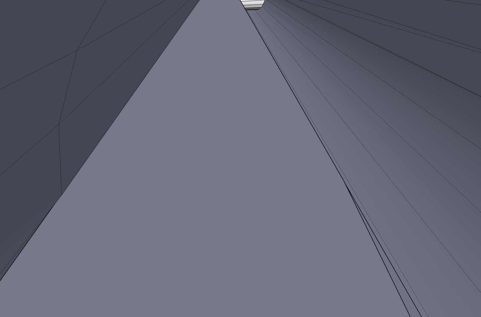
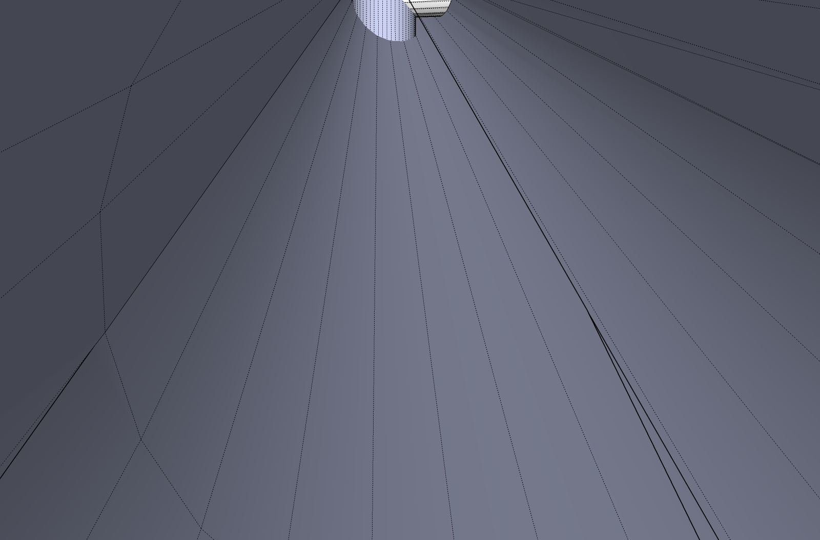
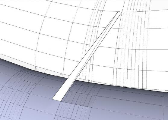
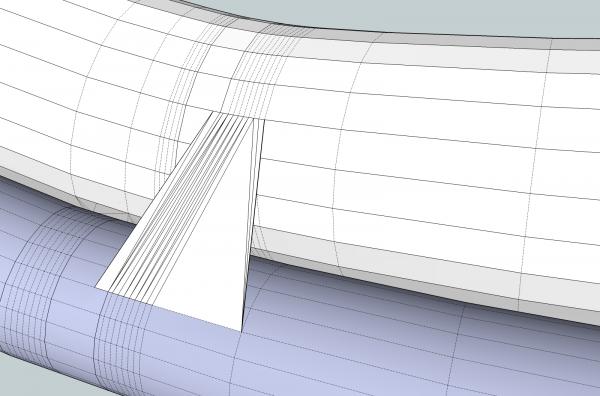
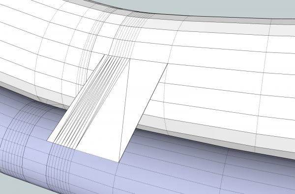
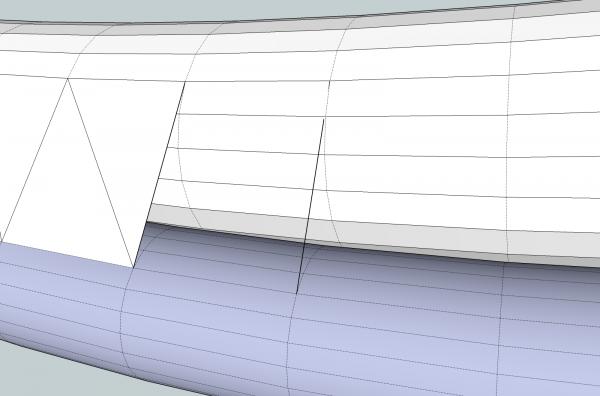
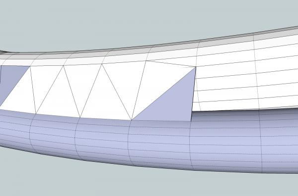
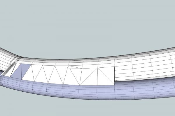
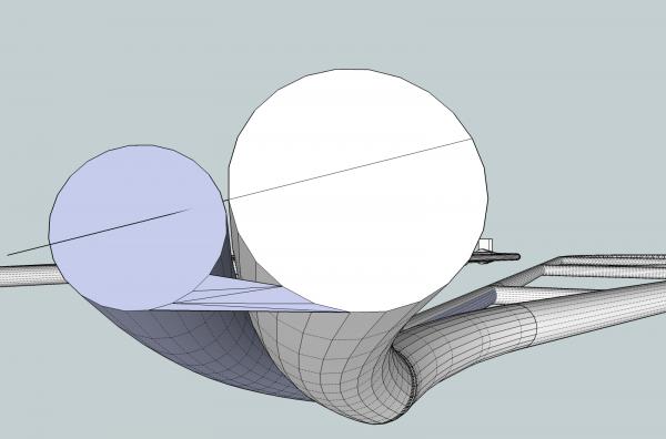
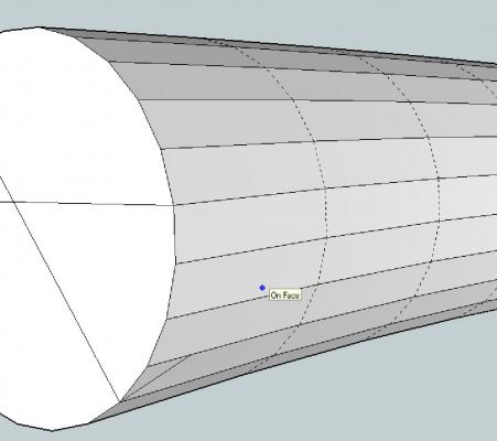
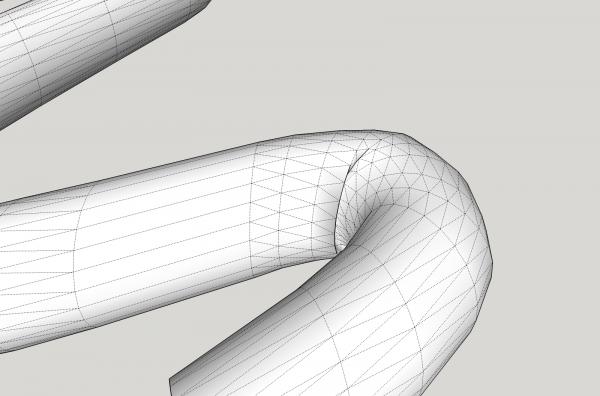
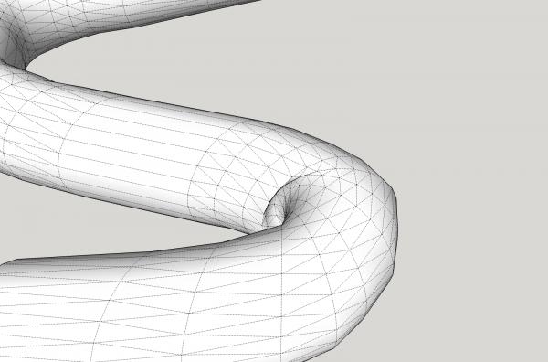
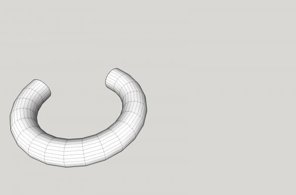
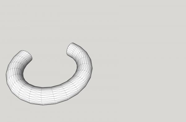
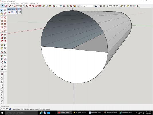
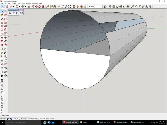
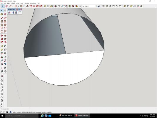
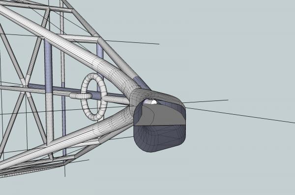
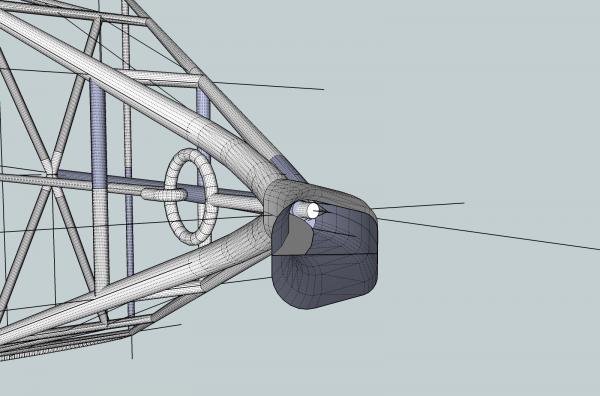
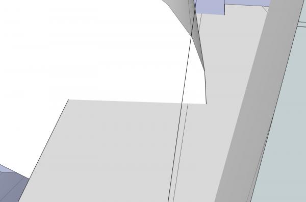
 Part 07B Now on to filling in along the length of the cylinders. A few things to note. Notice that the lines running along the length of the darker cylinder are dashed. SketchUp many times treats these as not lines when it comes to doing this filling in. You can see that in the area of the closely spaced surfaces, I have drawn a line over the edges along the length. Without the new lines, SketchUp would not create the surfaces. Yet on the longer sections, it did. The lines on the lighter cylinder are solid, and I did not have to draw over them. I do not know why SketchUp uses the two different types of lines, but be aware of the difference. In the picture below I have filled in more of the area. I drew triangle between the narrow surfaces, but ran out of matching ones on the dark cylinder, I attached the rest to the other end of the larger space. I could have done the same at the left, by continuing to connect to the left end point, as in the second picture. . I continued filling in the surfaces, until I ran into a spot where I had to change gears. As I went along I reached a point where the two cylinders had changed level, and I had to change the surfaces to another lower edge. Look at the right hand line, in the picture below. As you can see it dips below the surface of the lighter cylinder, I had to go down to the next line to eliminate the interference. I also drew a line from here to the upper line to connect the space. I then continued using the new spacing. Looking at the picture above, you can see extra lines on that first panel, where I change which lines were being used. These indicate that there is still some minor inference, but without a lot of effort to find the exact right spot for the line at the right side of the surfaces, this is good enough for our purposes. It will not hurt the finished printed part. More tips on filling in surfaces in the next post.
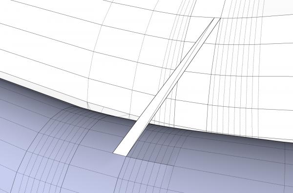

-
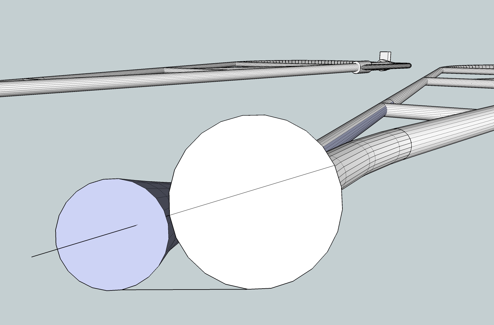
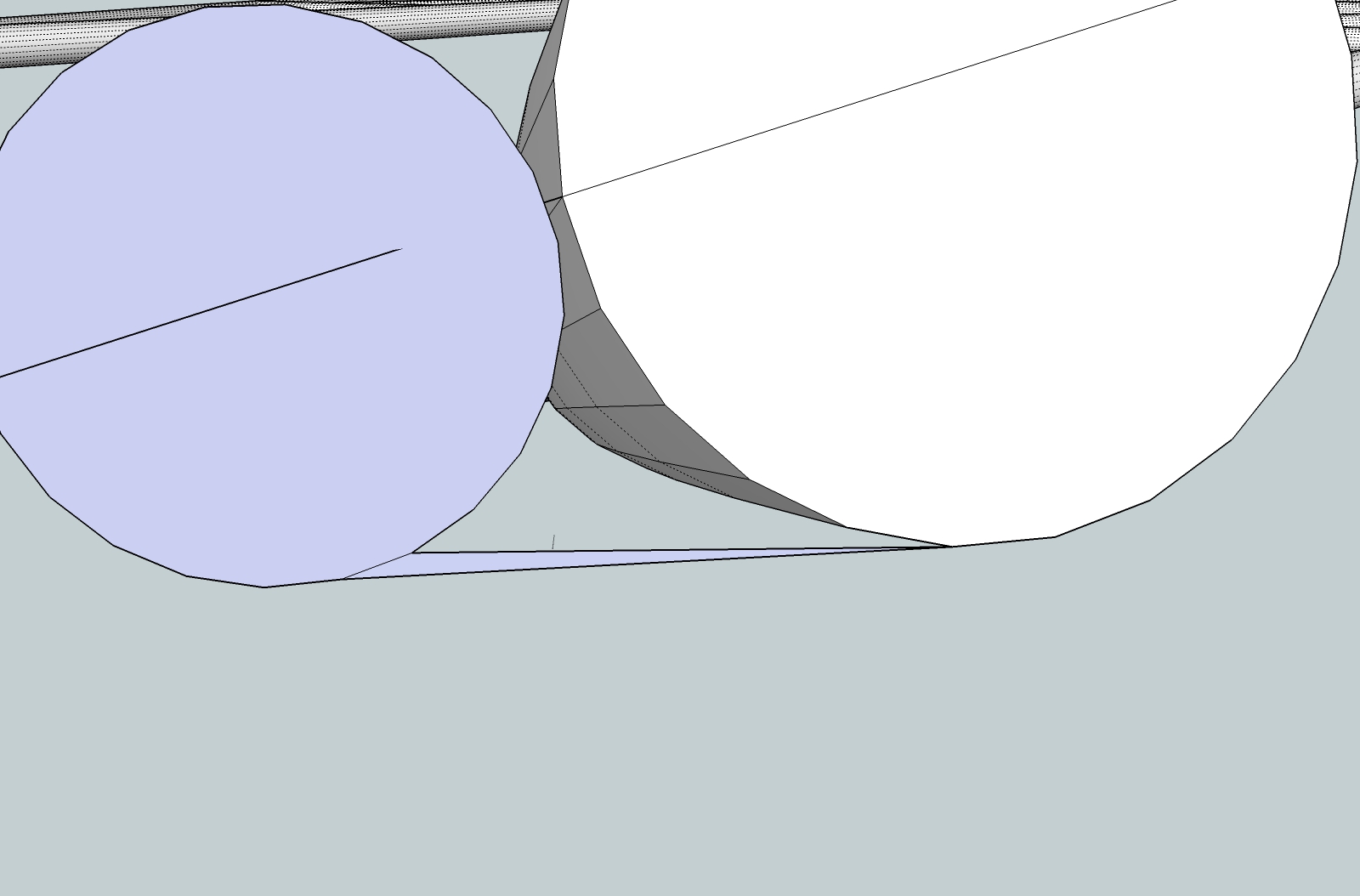
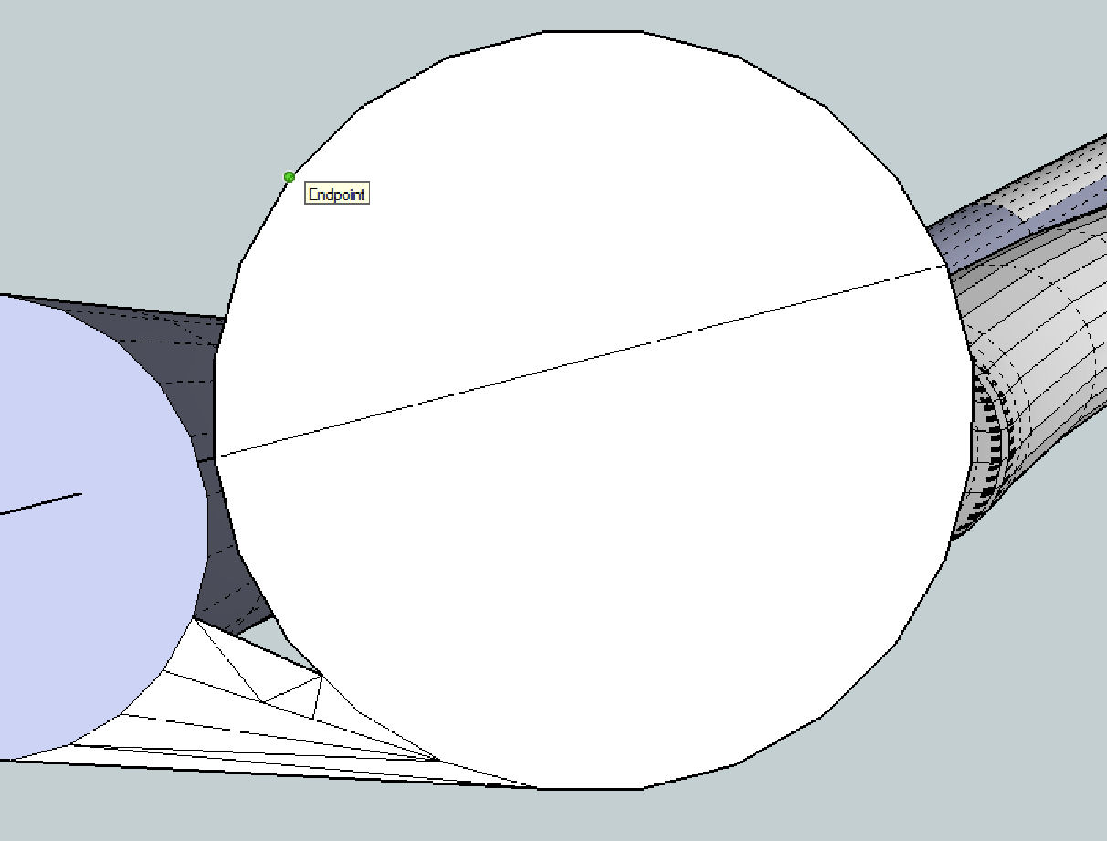
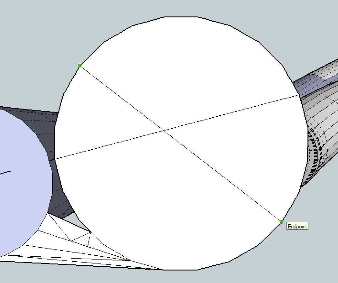
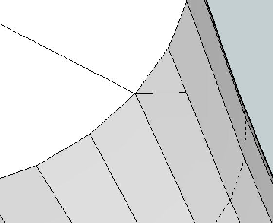
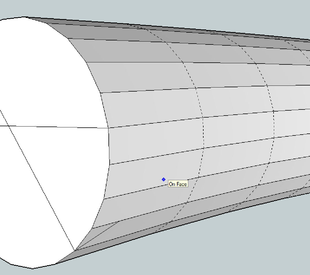
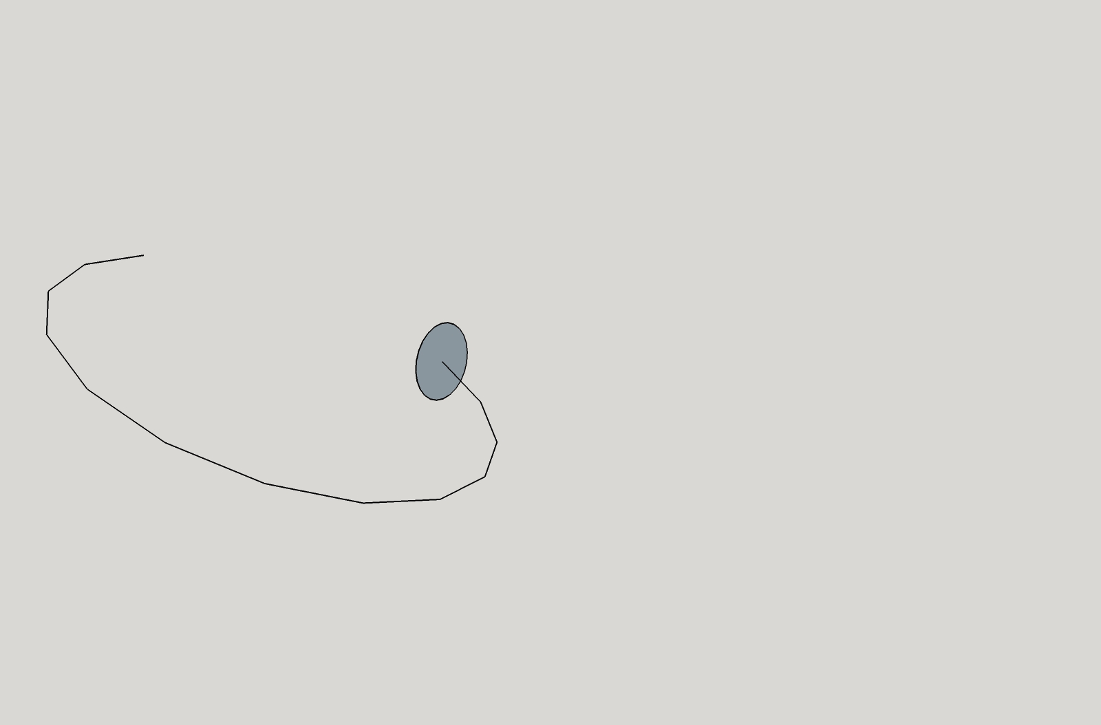
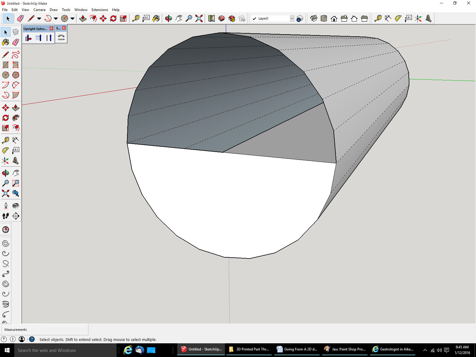
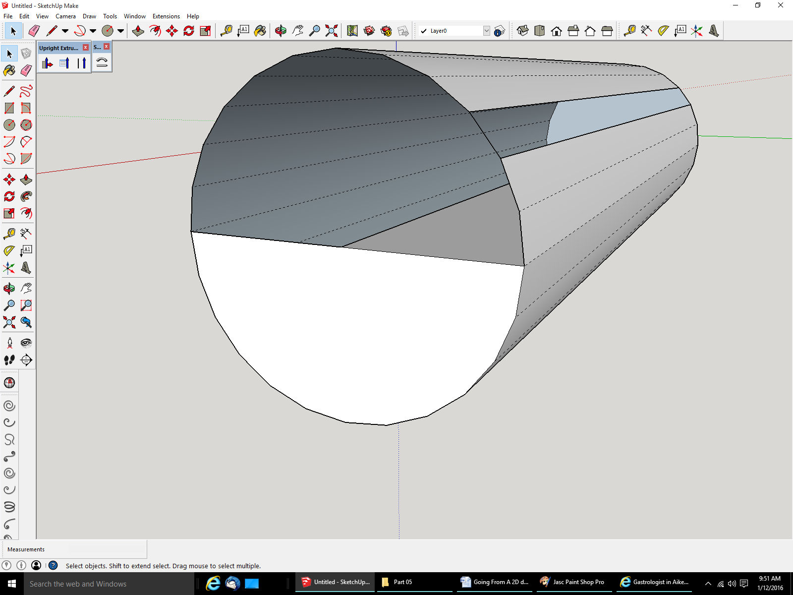
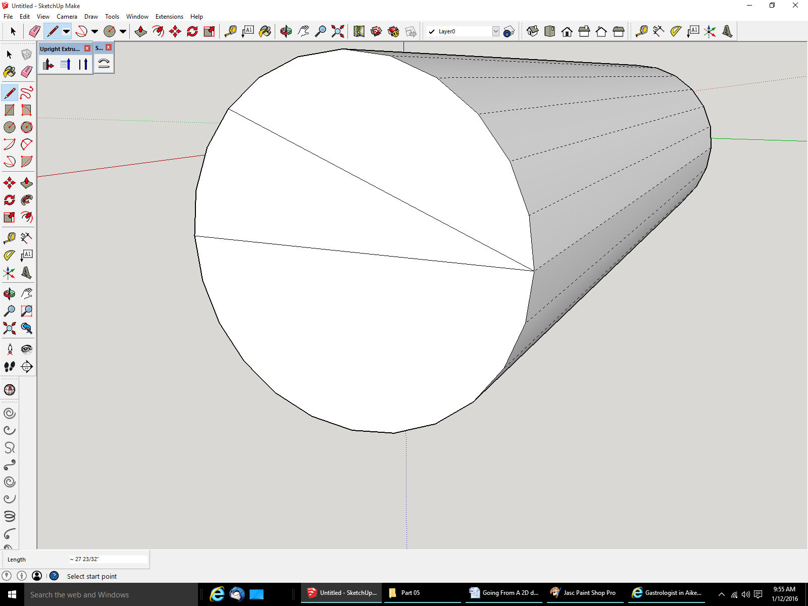
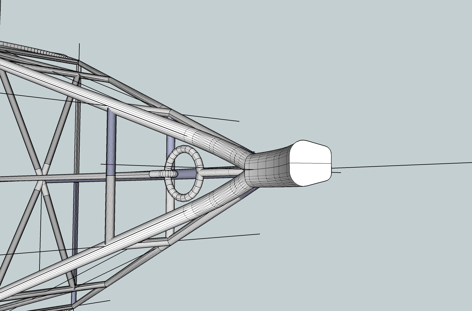
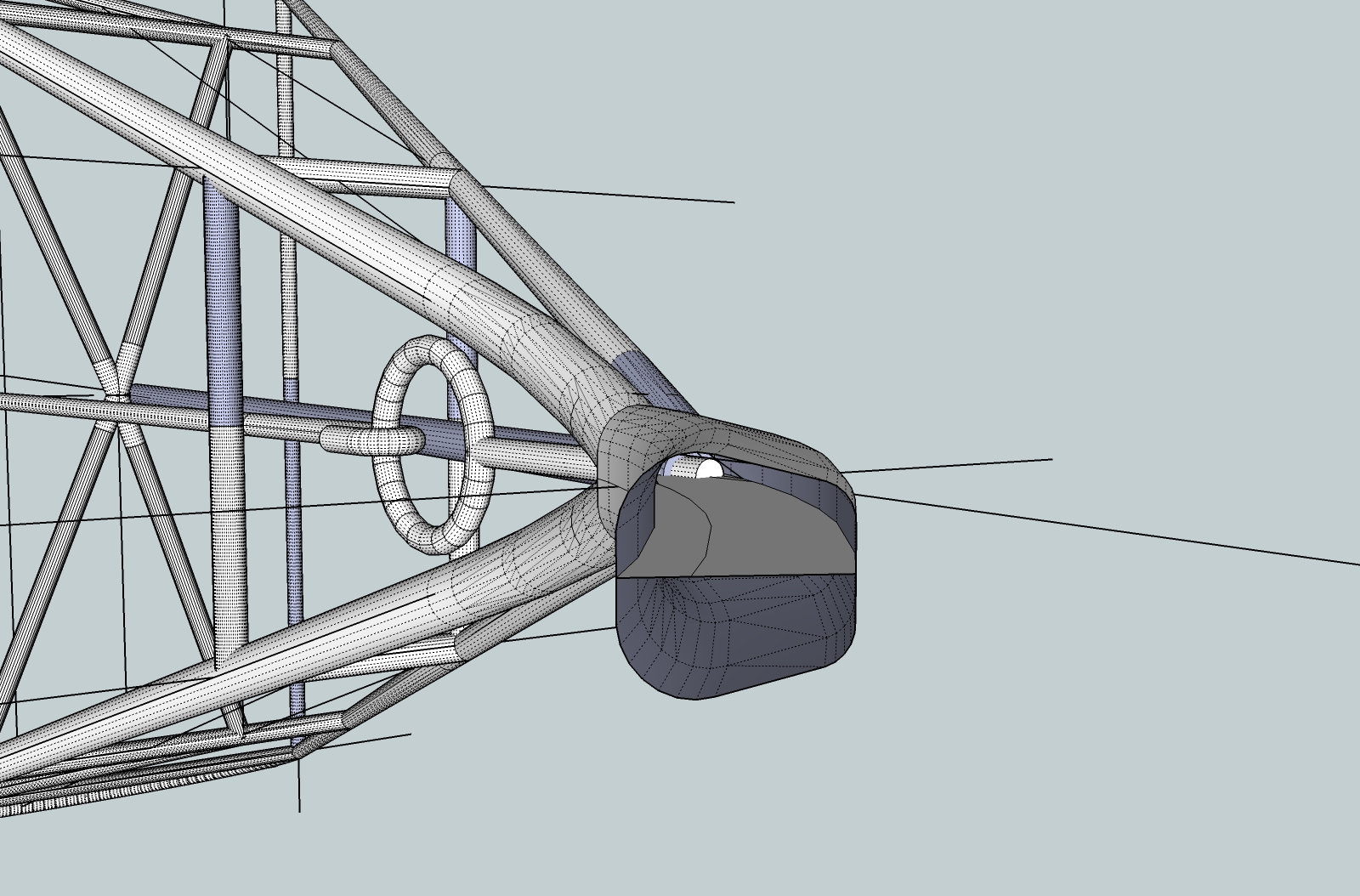
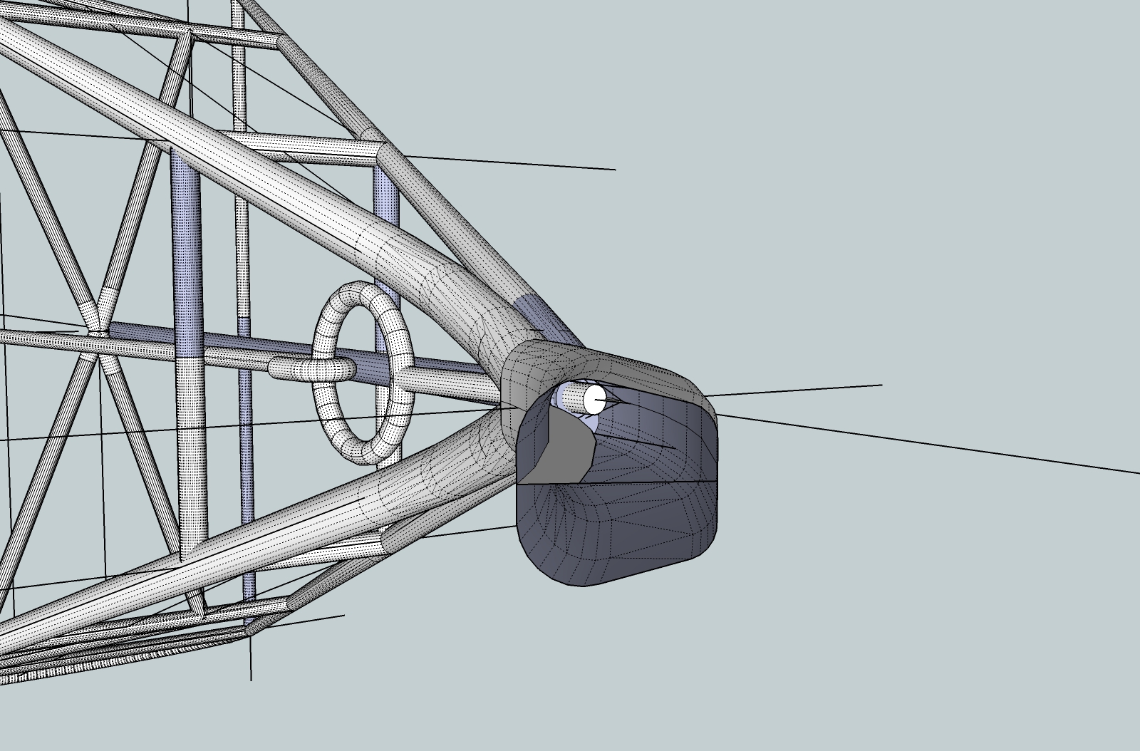
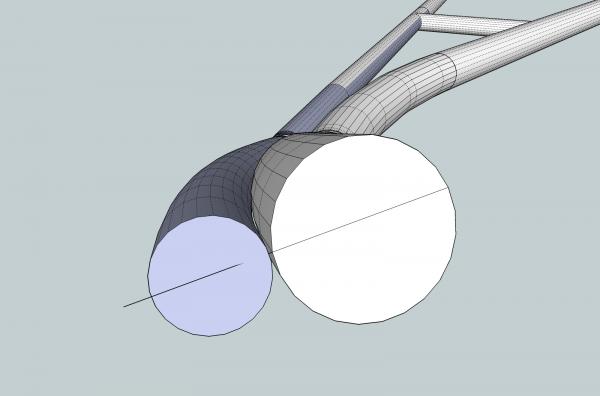
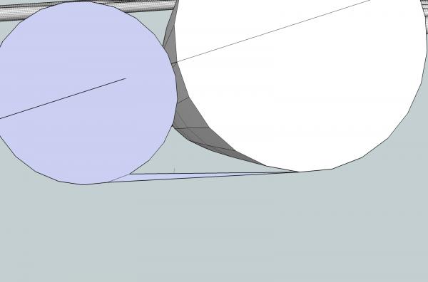
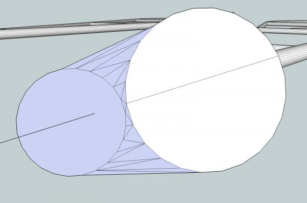
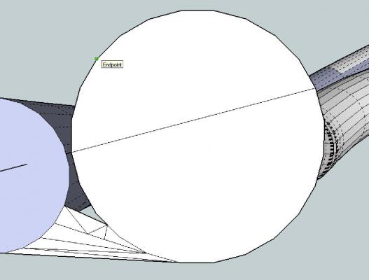
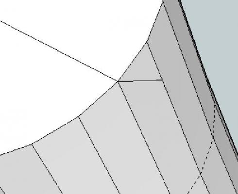
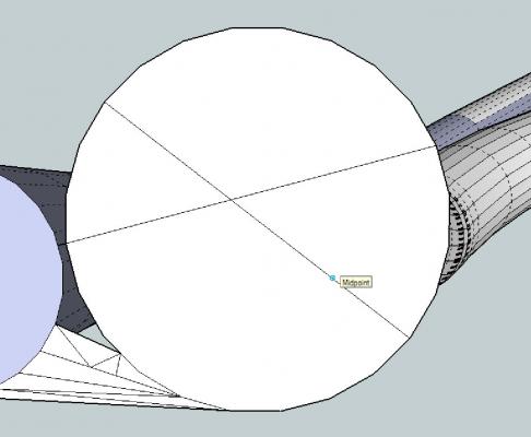
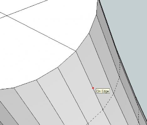
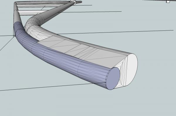
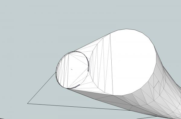
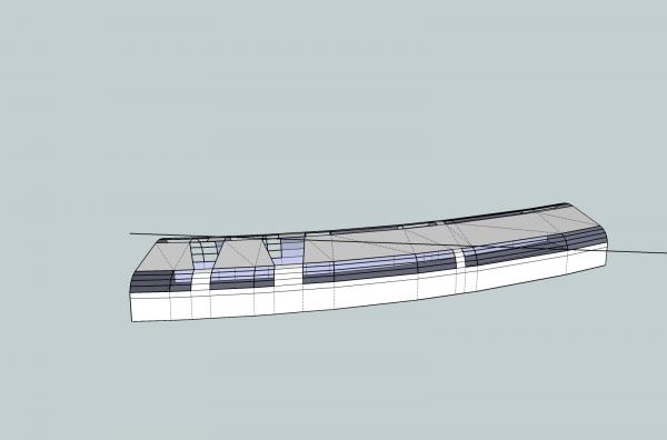
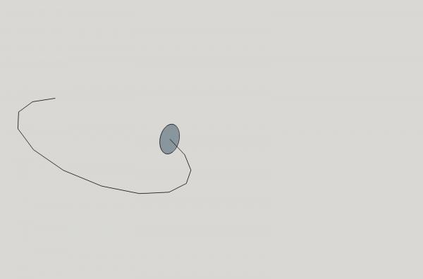
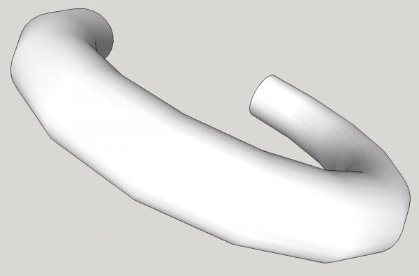
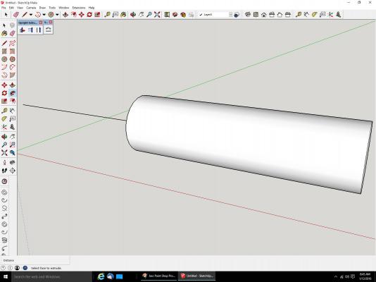
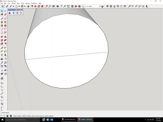
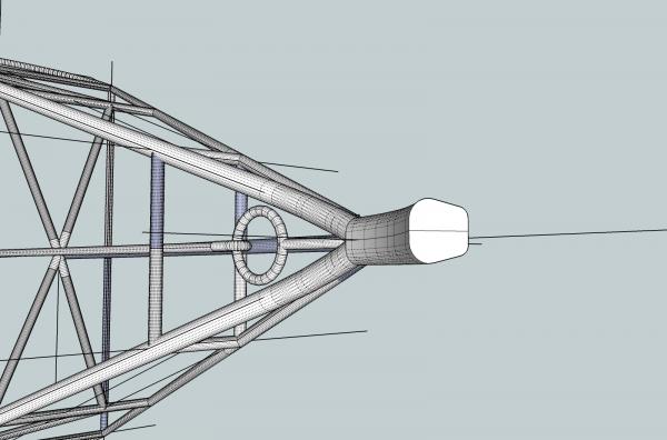
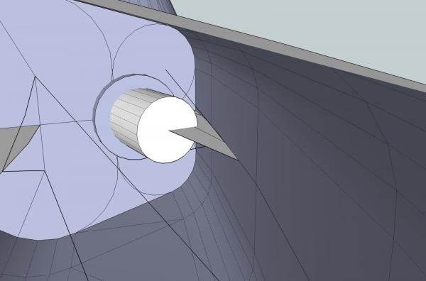
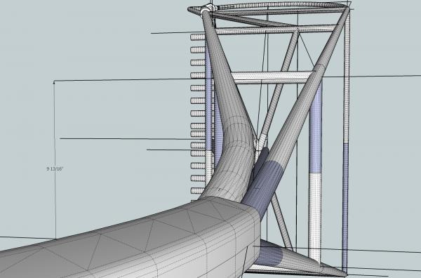
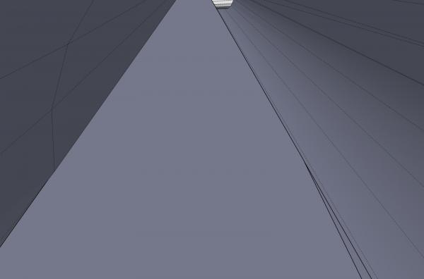
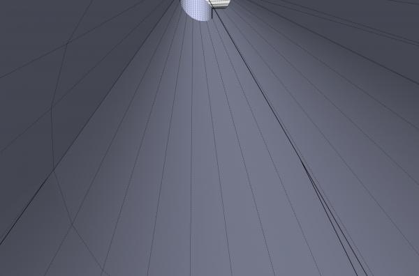
Part 07A Now I will discuss filling in missing surfaces, and filling in new surfaces between parts. There are two problems that may be causing the missing surfaces. The surface is really flat, but the program did not fill it, or the surface is not flat, and should be made up of two or more flat surfaces. Below is an example of both. The white end of the part is the first type, the horizontal surface is the later. Both can be fixed the same way, by drawing in triangles. By definition – any triangular shape encloses a flat surface, take my word for it. So the solution is to draw in triangles. Connect the end points to each other with triangles. The end shown has one end of the cylinder too long and in the next shot I will remove part of it to show the flat surface. What is an Endpoint? SketchUp endpoints are the end of lines making up an object. Look at the rim of the cylinders above. It is made up of a series of straight lines, that form a circular shape. The end of each individual line is an endpoint. When you are drawing lines, arcs, circles, etc. SketchUp will indicate when you are over, or very near an endpoint. If you click, it will snap to that point and set that is a point on your line. Then as you continue each time you are near and endpoint the program will show that to you. SketchUp will also show when you are near the middle “Midpoint” of a line. Notice that the Midpoint is not the middle of the line from one side to the other. Because the two long lines cross, (when on the same plain), SketchUp breaks them into four individual lines. So the Midpoint shown is the middle of that new individual line, of the four. SketchUp will also show you if you are on a line, but somewhere other than the above two points. This is indicated by “On Edge”. These aids will only be shown while you are drawing something. During normal mouse movement in other operations, they will not be displayed. These indicators are vital as you build your part. Navigation in 3D space takes learning, and a lot of patience. Unlike 2D drafting, where everything is on a single plain, and where your mouse is, is actually where you are. In 3D space your mouse may actually be touching something in the far distance. When you draw a line, you may think you are drawing a horizontal line, when it is actual also going away from you, so it goes in an entirely different direction, and may be connected to a point far behind, or in front of the place you want it to go. Frequent checking is required. This line looks to be horizontal from this view. But when we scroll to a view from a different angle, we can see that it really runs down along the face of the side of the cylinder. Navigation in 3D space takes some getting used to, and can be quite frustrating at times, but SketchUp is not unique in this problem. Maybe someday we will have 3D holographic displays, but while we still have flat screen monitors, it will be a problem. For the discussion of filling in a surface, I will use the following drawing. The task is to draw a surface across the two ends, like we had glued a sheet of paper over them, and to connect them along their length. On the dredge frame, this represents the ends being welded together. I will start with connecting the ends. You will notice a difference in the finished product from the example above. In the picture above, the end is truly flat, as in the first and second pictures in this post. To save time and effort on my part, I will be connecting the ends, but they are not on the same plain. The darker cylinder is slightly longer, in this earlier version. So what I will end up with is a series of flat surfaces that fill in the area, but are not all in a line. In the second picture I show where, with a flat surface, the end of the cylinder can be erased, to bring the end truly flat. Is does show that you can connect parts that do not line up. I will fill in the space by drawing in a series of triangles, until I have connected the area I wish to fill. When drawing the triangular surfaces The best way to get a good surface is to draw the lines so they end on an endpoint. I will show later what can happen when other points are chosen. To start a line is drawn for the bottom of the area to be filled in. Normally I would draw in the line for the top of the area, in the hopes that they might line up, and I would be finished. In this case I tried that, and failed, so I erased the line, and will fill the area , piece by piece, to show you the process. Remember connect endpoints. I drew in a line from an end of the line for the bottom of the area up across to the endpoint just up from the other end of the line. Right to left, in this case. I then starting from the left end, where I had just finished, I drew a new line up to the next endpoint on the right. Continuing in this fashion, I continued to fill in spaces.


-
I though I might be going into too much detail.
-
Is this tutorial going in the direction you guys want, or would you like me to take a different course?
-
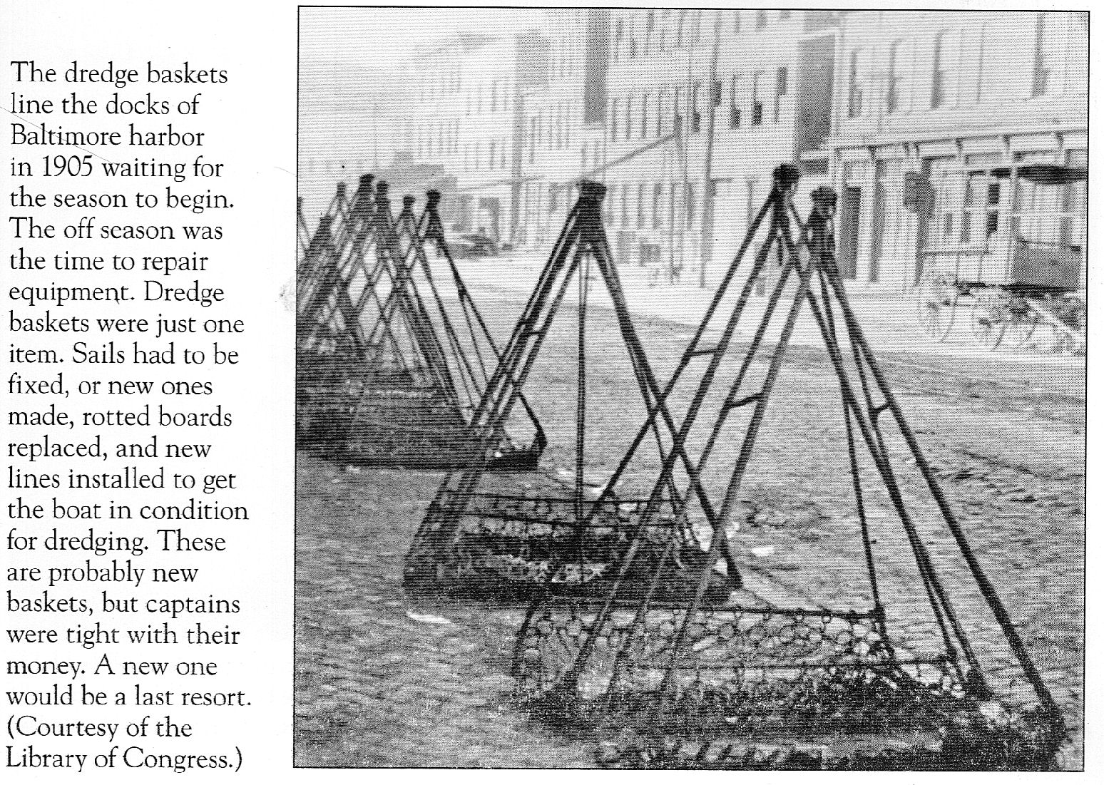
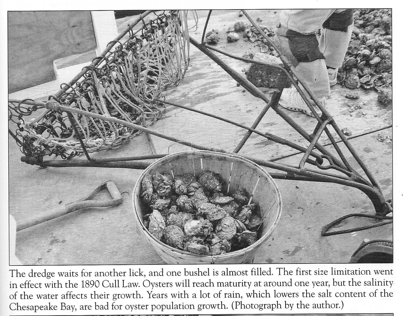
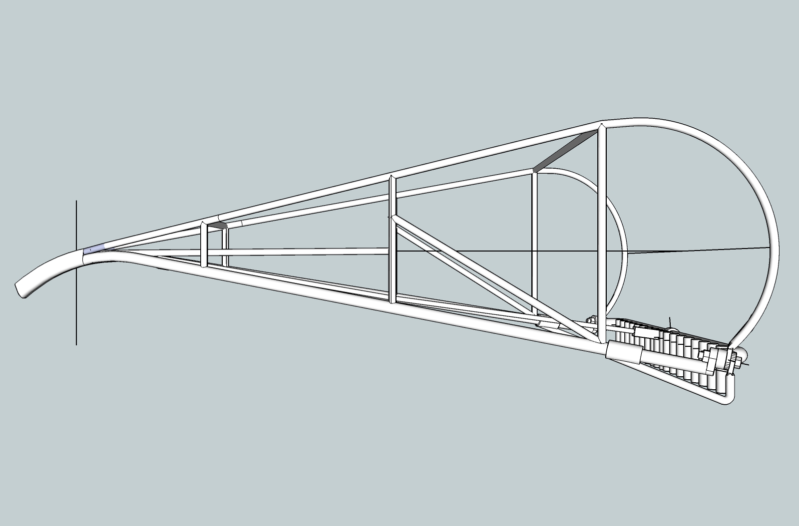
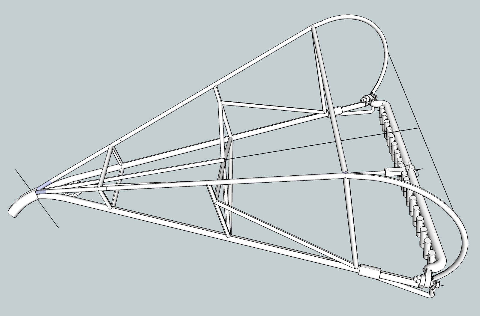
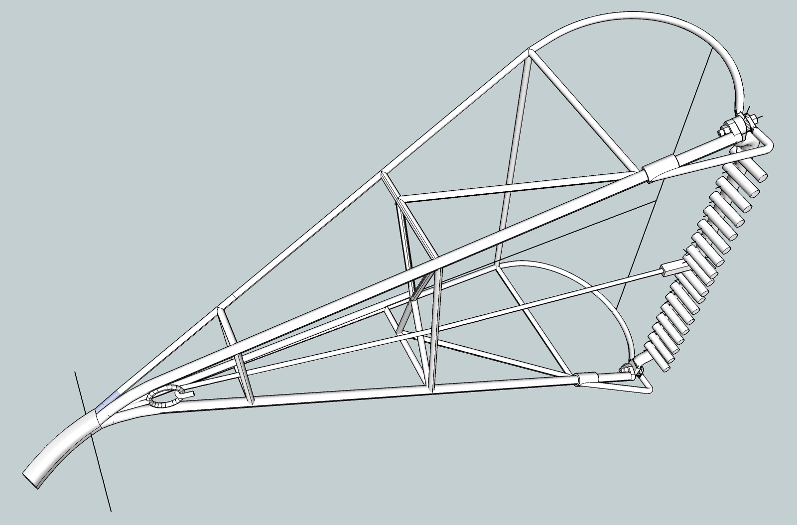
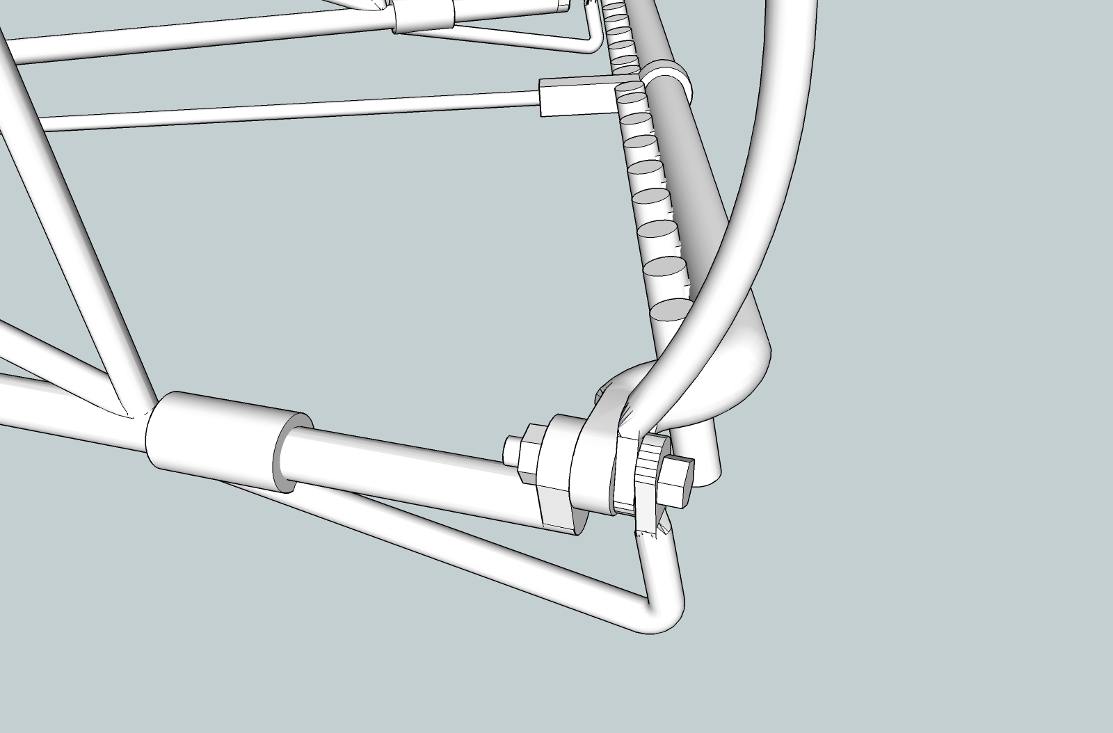
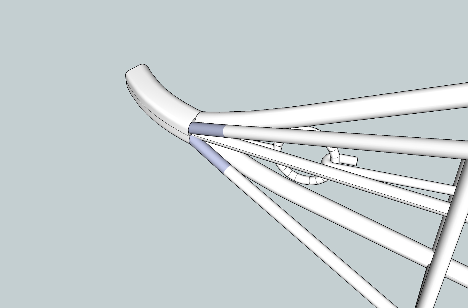
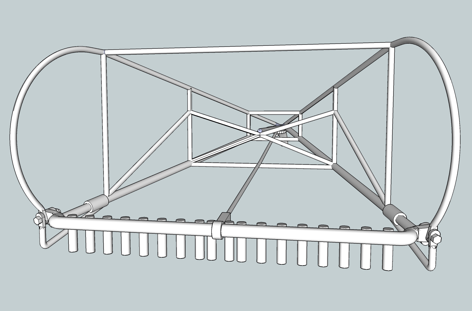
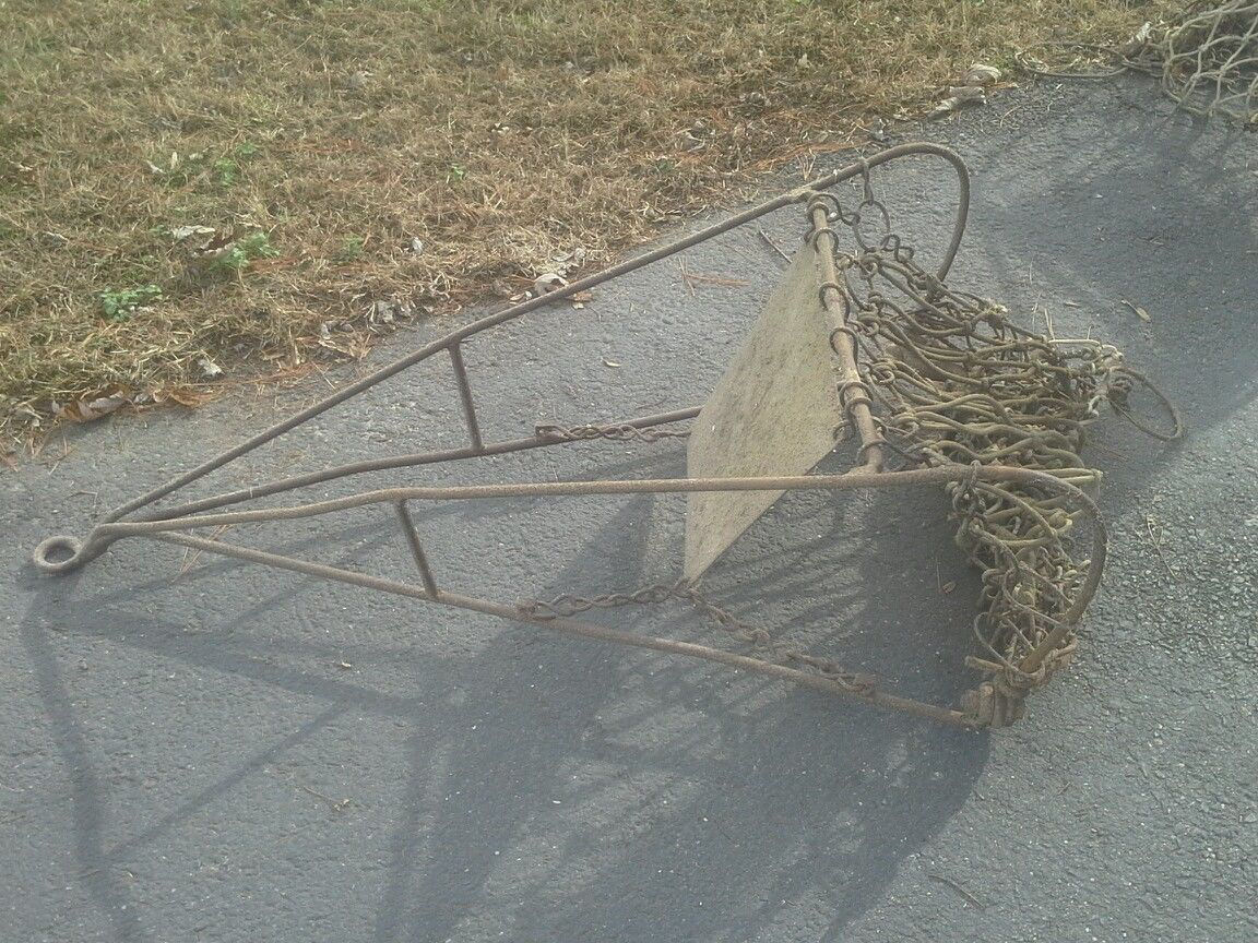
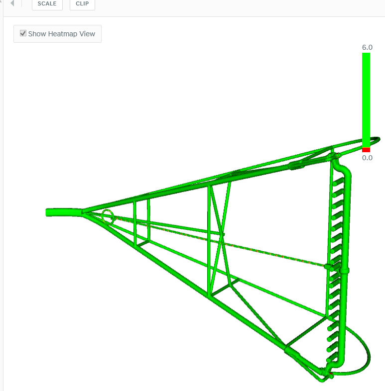
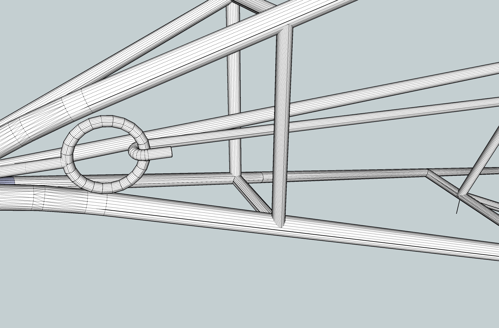
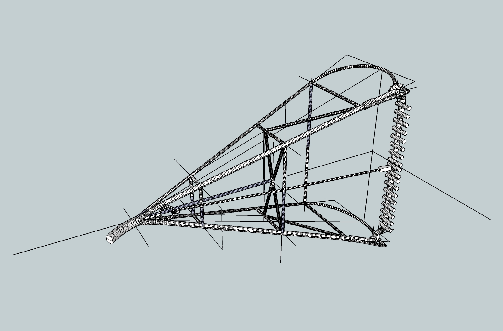
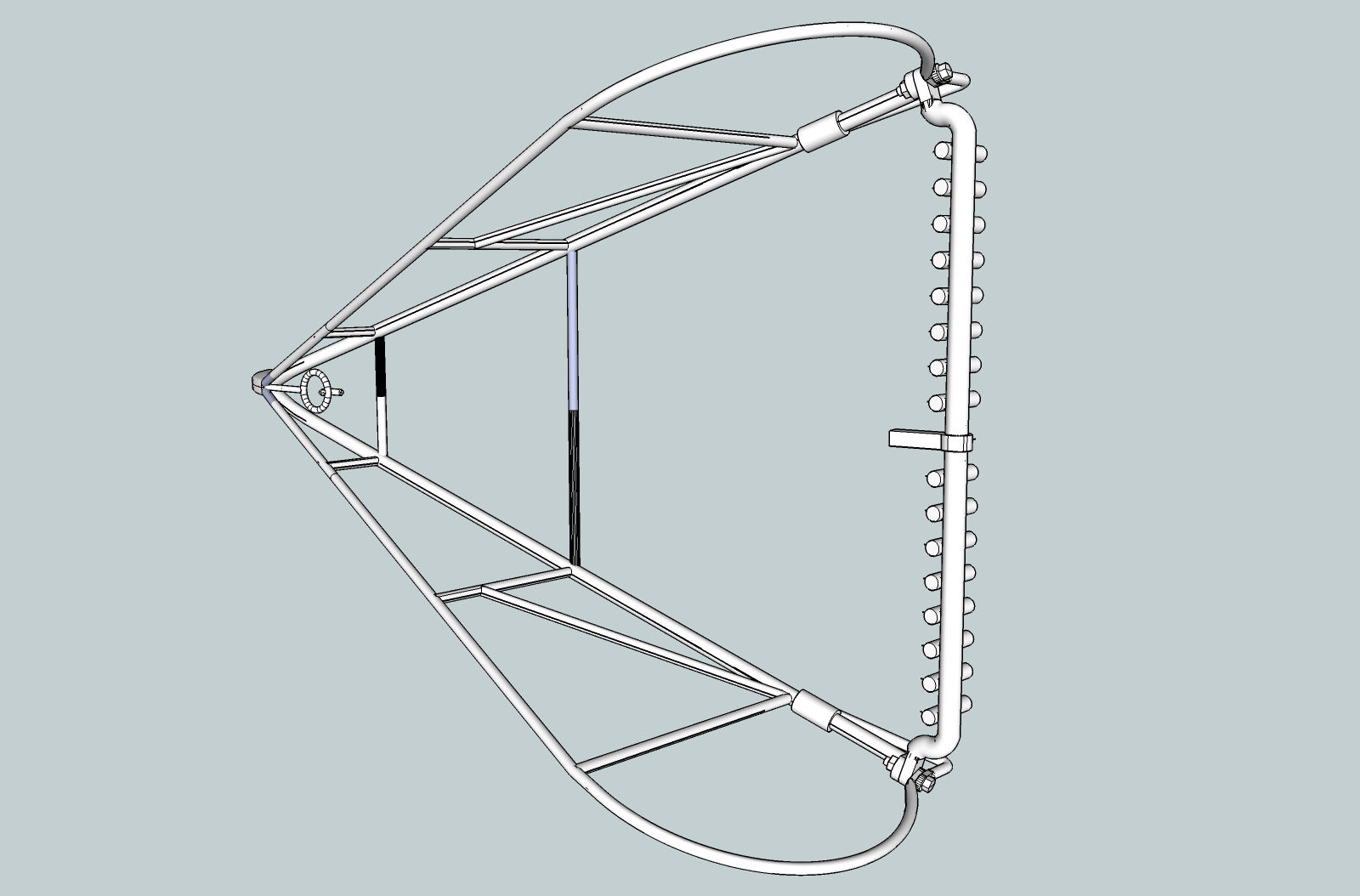
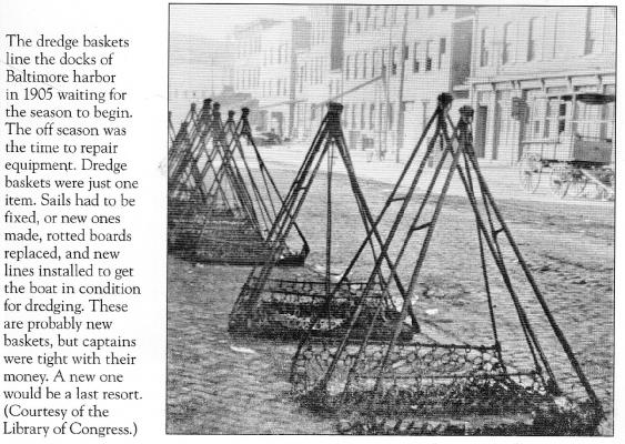
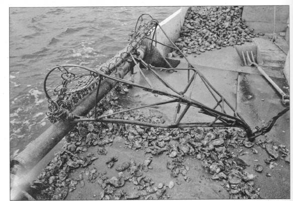
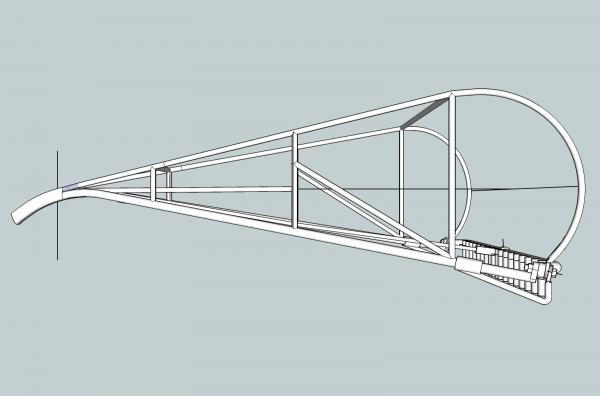
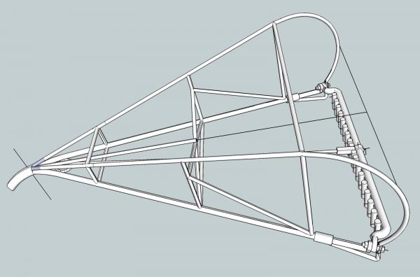
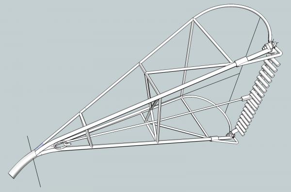
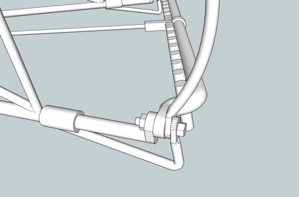
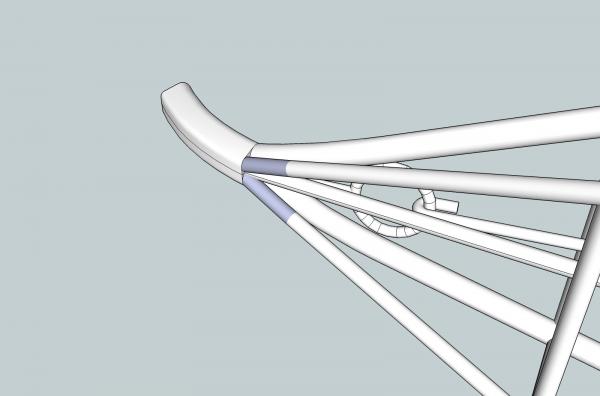
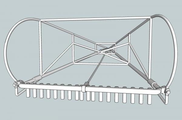
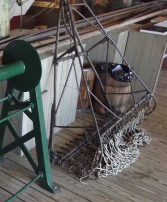
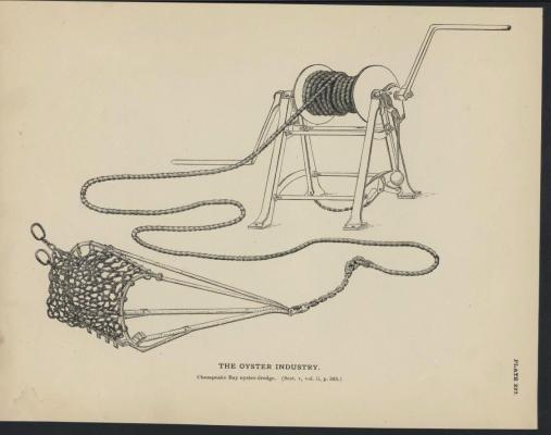
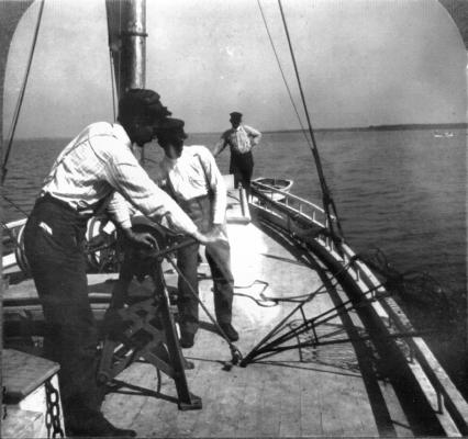
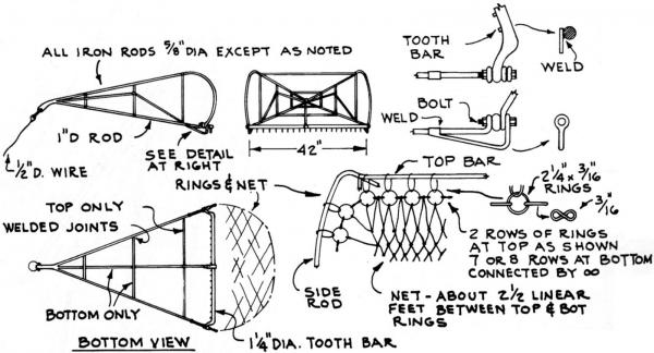
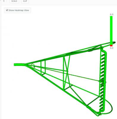
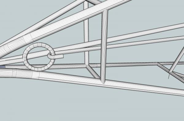
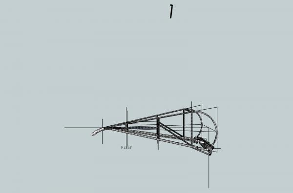
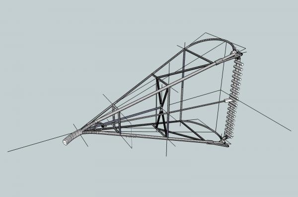
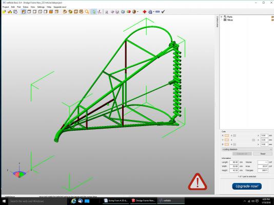
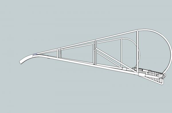
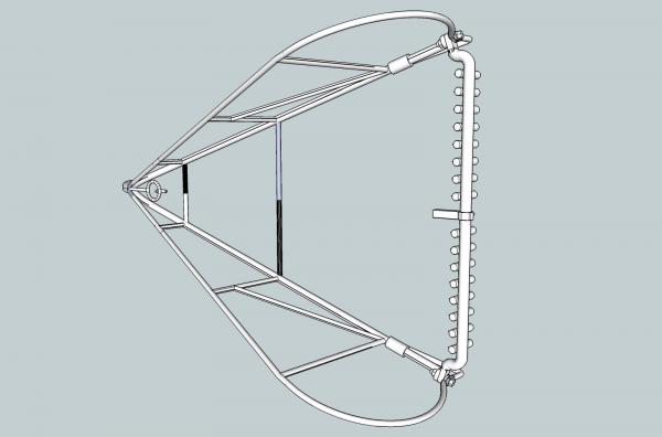
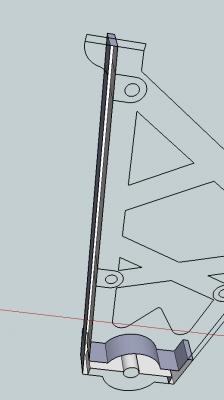
Part 27 The wood for the mast and boom have not arrived yet, but I finished the drawing for the dredge frame in 1/32nd scale. I’ll order a set at the beginning of the month. This is the frame drawing from the Willie Bennett plans. It has decent detail, but not as much as I think it should. This is from an old stereographic print Of course there is the dredge in the hand winch photos. And even a picture of a dredge that was on sale on EBay! Wish I could have bought that one. This is the print from the Fisheries' book, that I showed in a previous post. I bought a book “Images of America Maryland’s Skipjacks” that had several photos showing a dredge. After looking at these pictures, I decided to draw a more complex frame, using some of the details from the pictures. What I got from these pictures, is that there were many different designs, and just about anything resembling a dredge would be correct on a model. In the first book picture, showing frames at the docks in Baltimore, some of the dredges have bottom braces, and some don’t. I particularly like eyelet and hook arrangement for the bottom brace on this last picture, and decided to use this on my dredge. The dredge in the winch photo also has a hook and eye arrangement, though of a different design. Having the dredger bar bolted to the frame, then welded to the bottom brace, making removal impossible, also did not make sense to me. What I settled on was a frame like the Bennett drawing, but a bottom brace like the last picture above. The front of the dredge in the Bennett drawing is a blunt end, with a ring. I made the front end a mass of the upper and lower bars welded together, with a blunt point which is the common configuration in the pictures. I will still use a ring, rather than a welded eye for the cable connection. This is my completed dredge frame drawing in 1/32nd. I have to redraw almost all of it for the 1/64th one, as I will have to make the diameters of the bars larger, to meet the printing requirements, though not a whole lot. The 5/8” upper frame bars will only have to be made a little large than ¾”. I want to increase the size of the rest of the bars, to keep the proportions correct. Close ups of the bolt area and the nose. This is a screen shot from the Shapeways site showing that everything is acceptable (all green, no yellow, or red). The only thing that worries me is that the model may sag during the printing process. If that happens I will have to break it up into sub-assemblies.

-
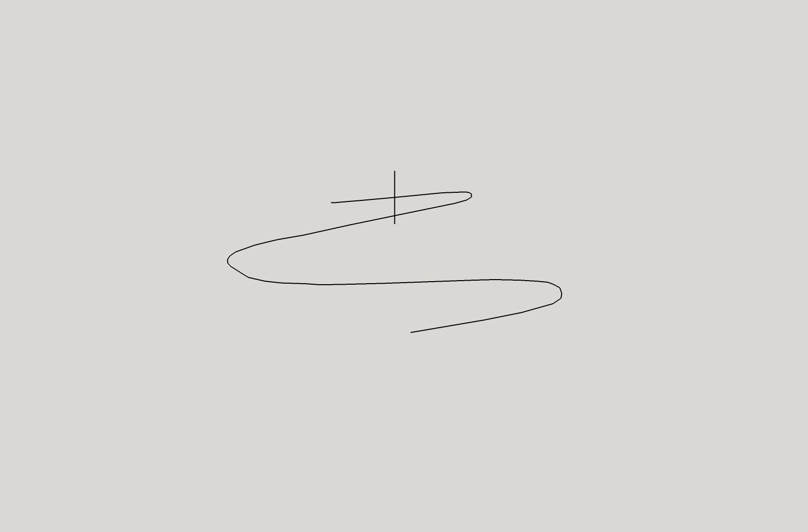
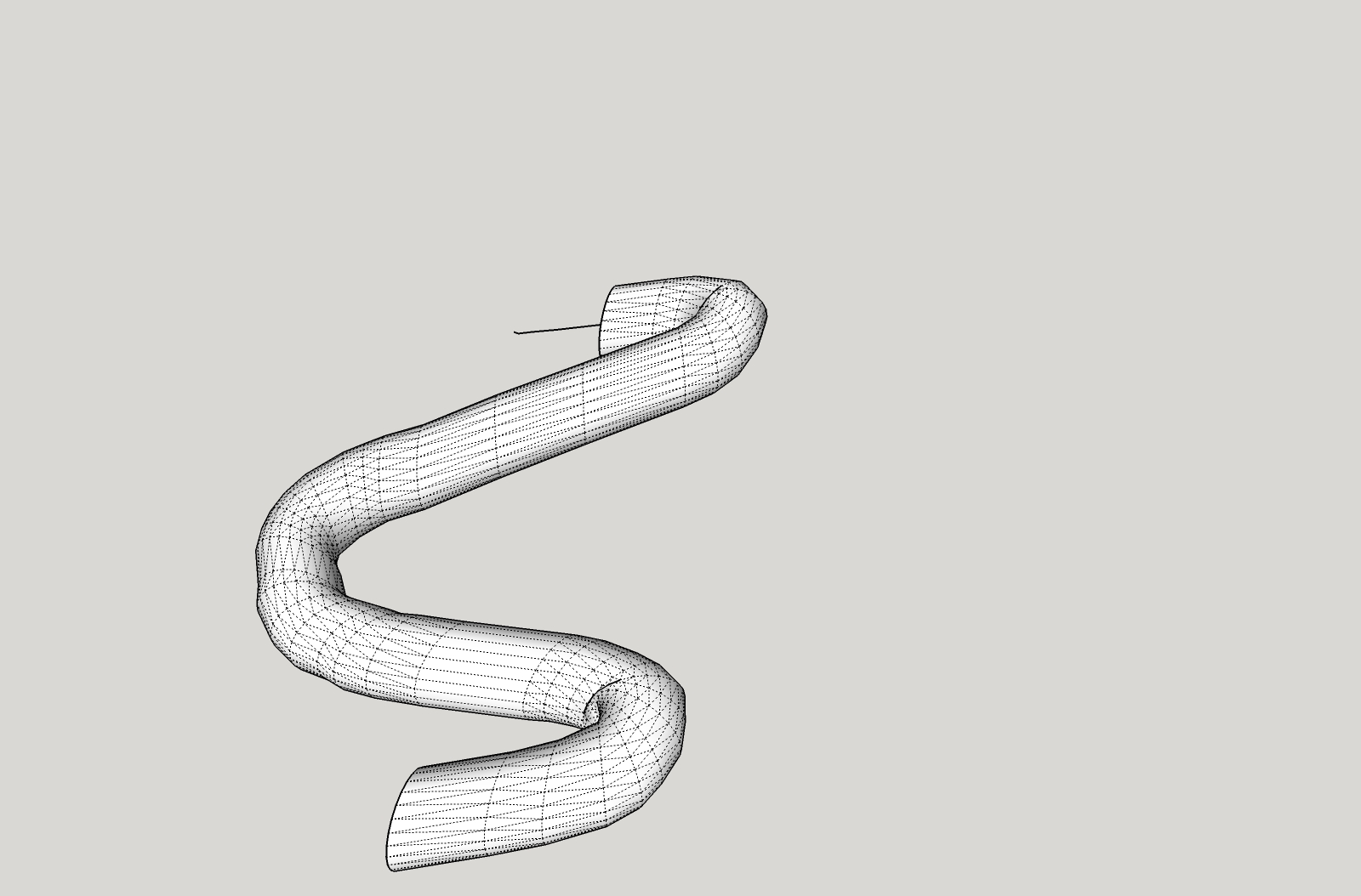
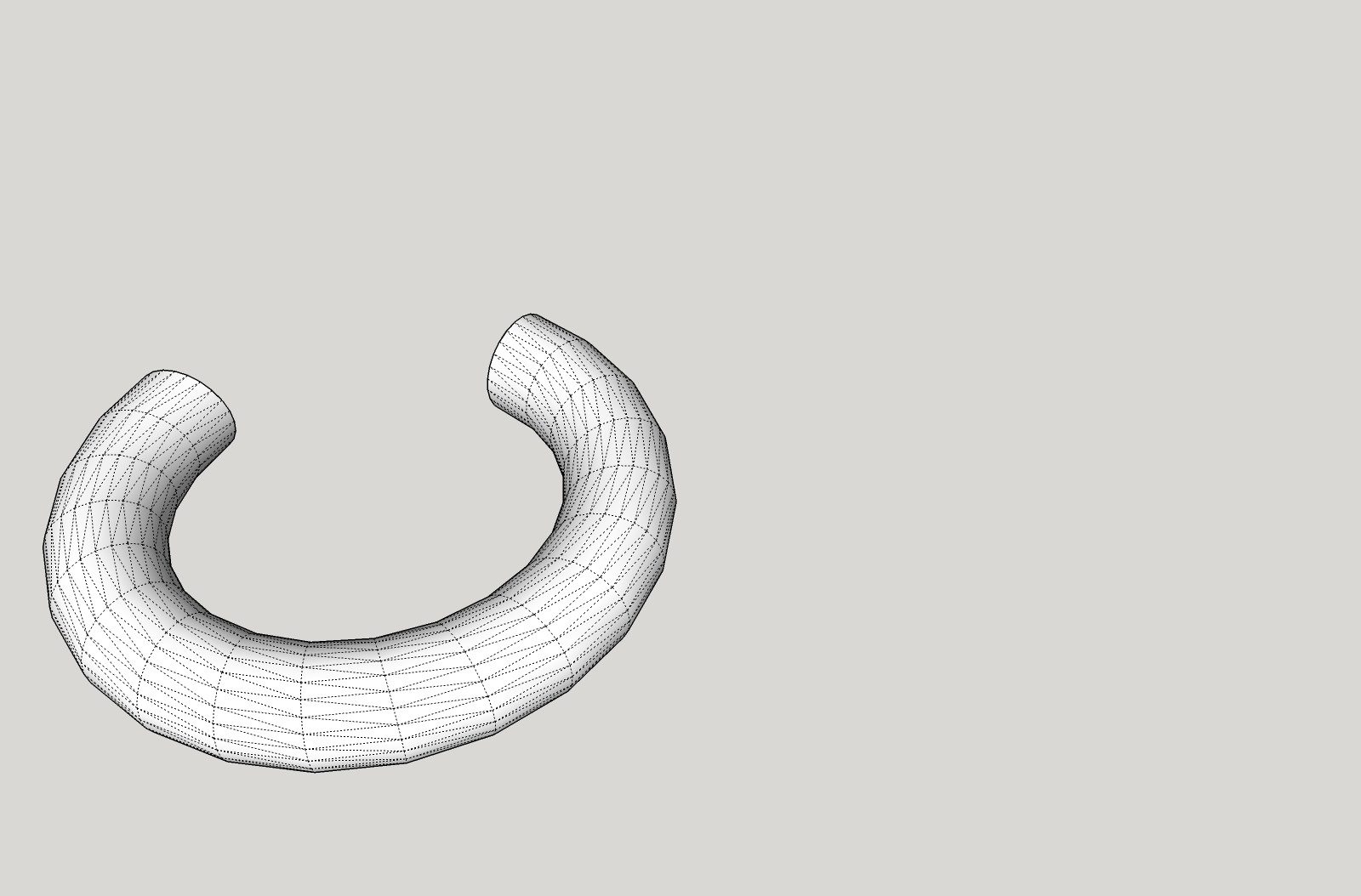
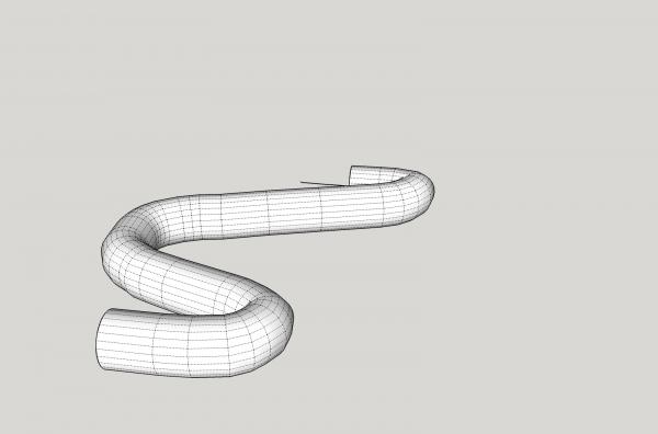
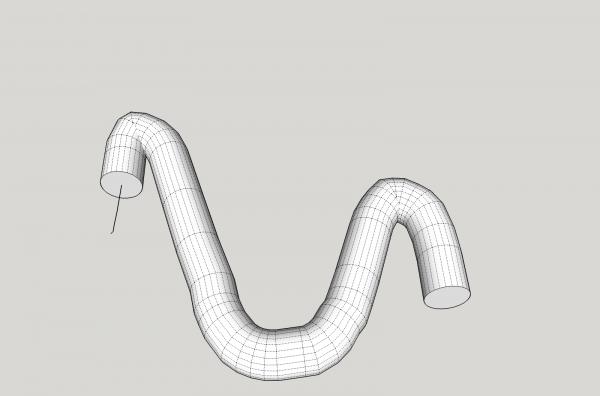
Part 06B Next is a bit more complex a path. One thing I will have to tell you here is that the surface is not perpendicular to the path, it is angled off somewhat in the vertical direction. You can see above that the path angles up, but the surface is vertical, not angled back somewhat to be perpendicular to the path. SketchUp should as you draw a line, snap when you are close to perpendicular to the line, and tell you so. With this complex line there were too many small lines for it to be able to do this, and I had to settle for vertical lines to make the cross. We are not making parts for NASA, so the slightly oval shape of the final solid will not be a problem for us. Anyway, back extruding. Follow Me makes this shape. From a higher viewing angle it looks like this. Using Eneroth gets this shape. The shape is distorted at the sharper curves. The distortion shown is a depression forming a sunken area. So if you can, use the Follow Me operation, and ways check for missing surfaces. To fill in missing areas may take some work. It could be as simple as drawing over an existing line like in Part 5, or it may take a lot of lines to convince SketchUp to fix the surface. The next part will discuss ways to fill these missing panels.

-
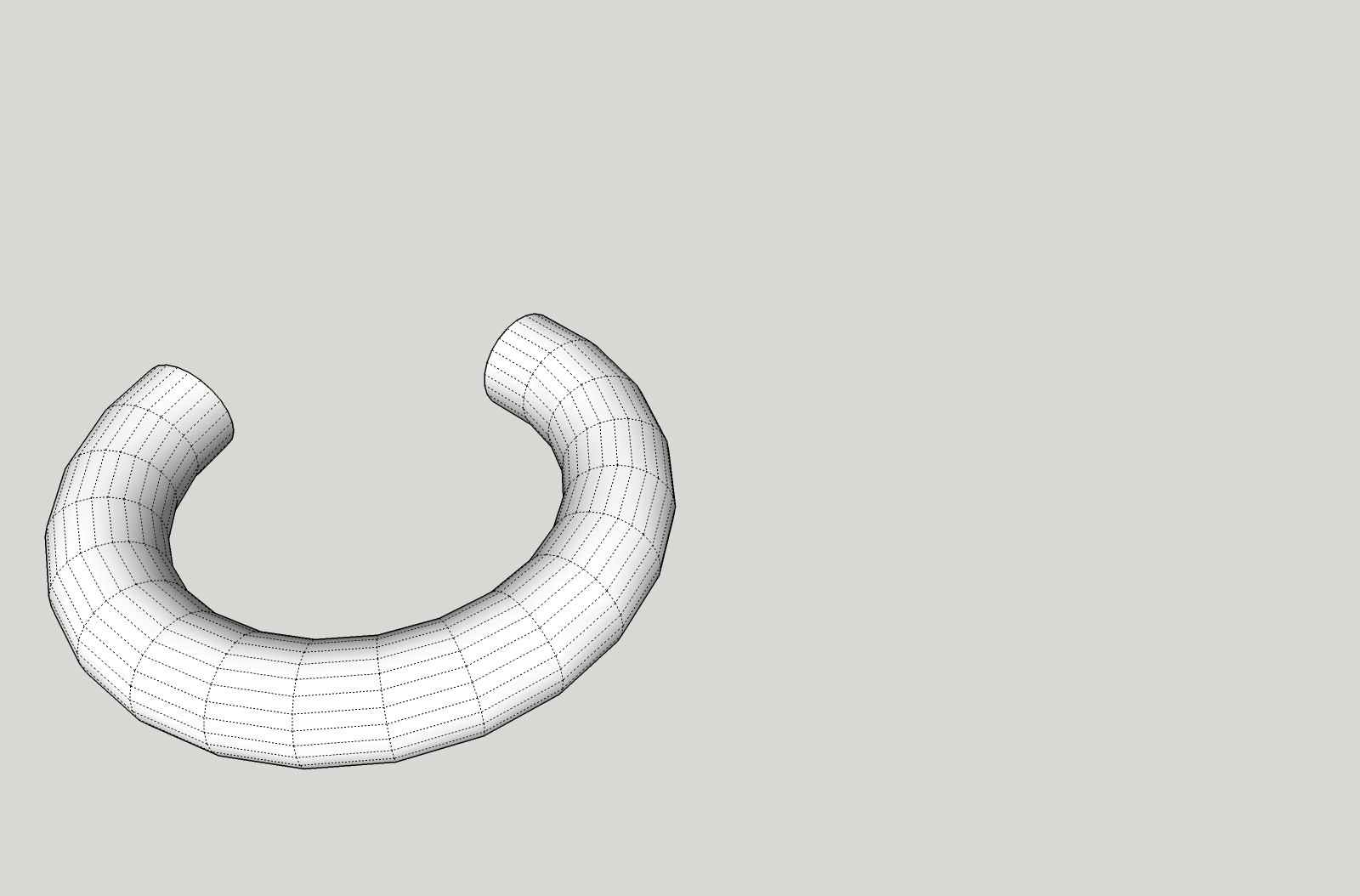
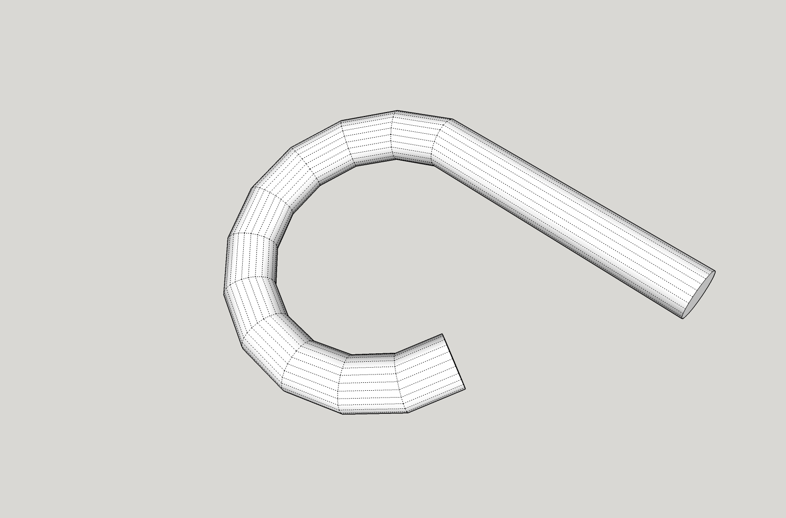
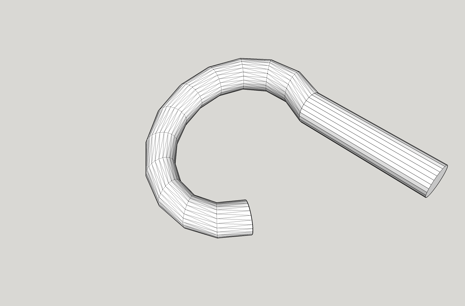
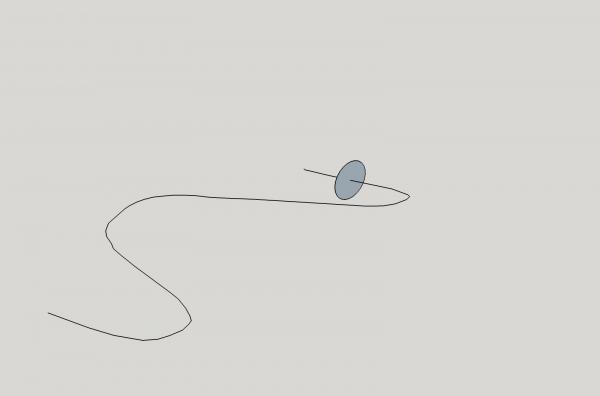
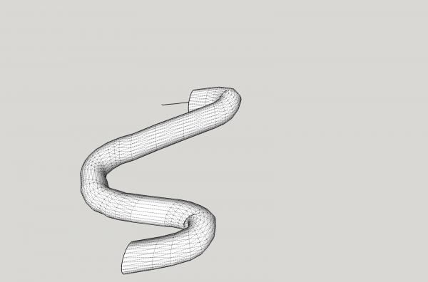
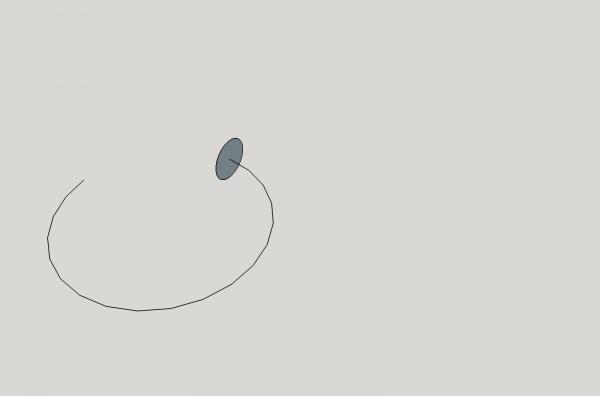
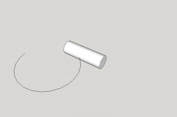
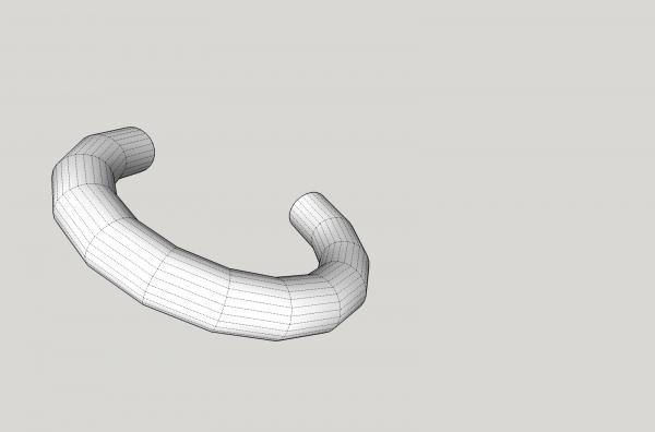
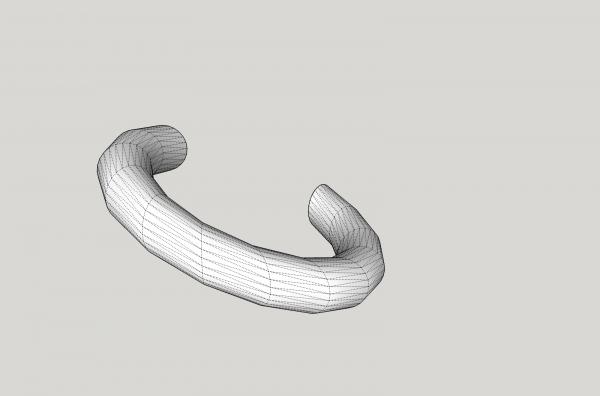
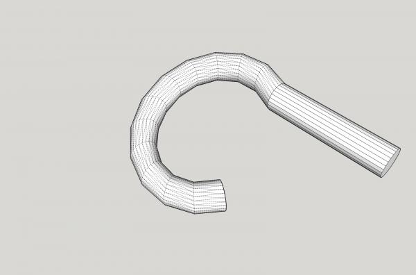
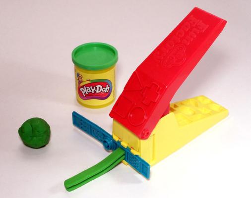
Part 06A As you can see from the label, this will again be a two part post. There are three main ways to extrude a flat surface into a 3D object. The ones that come with SketchUp are: “Push/Pull”, and “Follow Me”. The third is from one of the add on plug-ins “Eneroth Upright Extruder”. They operate in different ways to extrude the surface. What is extrude? Think of the press Play-Doh makes were you force the Play-Doh through a shaped hole to make a column with the cross-section of the shape in the Doh. The three tools above operate in a similar fashion taking the surface and extending it along the path you choose. In this part I will talk about the differences in the way they work. While “Follow Me” and the Eneroth extruder work in a similar fashion, there are differences in what you end up with. The “Follow Me” more frequently gives you a 3D shape that is truer in cross-section than the Enenroth, though the Eneroth will sometimes times work, where the “Follow Me” will tell you it cannot do the operation, and visa-versa. The Eneroth will also many times give you a better shape than the Follow Me” for complex paths. I generally try both, and pick the one that looks better. The difference between the two are how they extrude the surface. “Follow Me creates a new face, at the junction of the lines, perpendicular to the line(s) that are the path allowing the surface to angle up or down with the path, if it is angled. Follow Me then connects the faces The Eneroth always keeps the face vertical, so some distortion of the shape may occur. After creating all the new faces, both then connect them with surfaces to fill in the shape, and delete the interior faces, leaving you with a hollow solid.. Note: that sometimes both commands will leave the inside faces, giving you a series of chambers inside the shape. These can sometimes act as the hidden interior walls I talked about in the previous post, when you go to export the file for the 3D printing. This happened to me on a ring I made as part of an eyelet for the dredge frame. I would export the file and the ring would show up, the another time, it was missing. Deleting the interior surfaces solved the problem. It took awhile to find this. Both “Follow Me” , and the Eneroth one will sometimes leave a shape with missing surfaces, that you have to manually fill. Let’s start with a simple flat curved path. The Push/Pull command will only extrude the surface in a straight line, not what we want for this. The Follow Me creates a solid like the one below. Each of the joints where the solid has a joint, are where the lines changed angles to make the curved path. The Eneroth extruder creates a solid like the one below. You can see that the outside shape of the solid has many more surface segments, giving it a slightly more rounded shape. These two solids come out looking similar after the extrude. Next we will see what happens if the path is angled up. Using Follow Me creates the shape below. The above is how it looks with the Hidden Geometry turned off, this is how it looks without the outlines of the surfaces shown. This is what your printed part would look like. Now to see the difference in the Follow Me and Eneroth operations see the two shapes created. The Follow Me shape. The Eneroth shape. Notice how the joints are vertical in the Eneroth shape, not following the slope of the path, as in the Follow Me. As I said above I generally try both ways, and choose the one that either is the only one of the two that worked (obviously), or the one that produced the better shape. Next we will create a hooked shape by extending one end of the shape using Push/Pull, to see what happens in each type of shape we made. Extending the Follow Me does this. While the Eneroth looks like this. Generally, but not always the Follow Me comes closer to what you want. One thing to note is that all these commands will only extrude a flat surface, not a curved section, which is really made up of several surfaces.


-
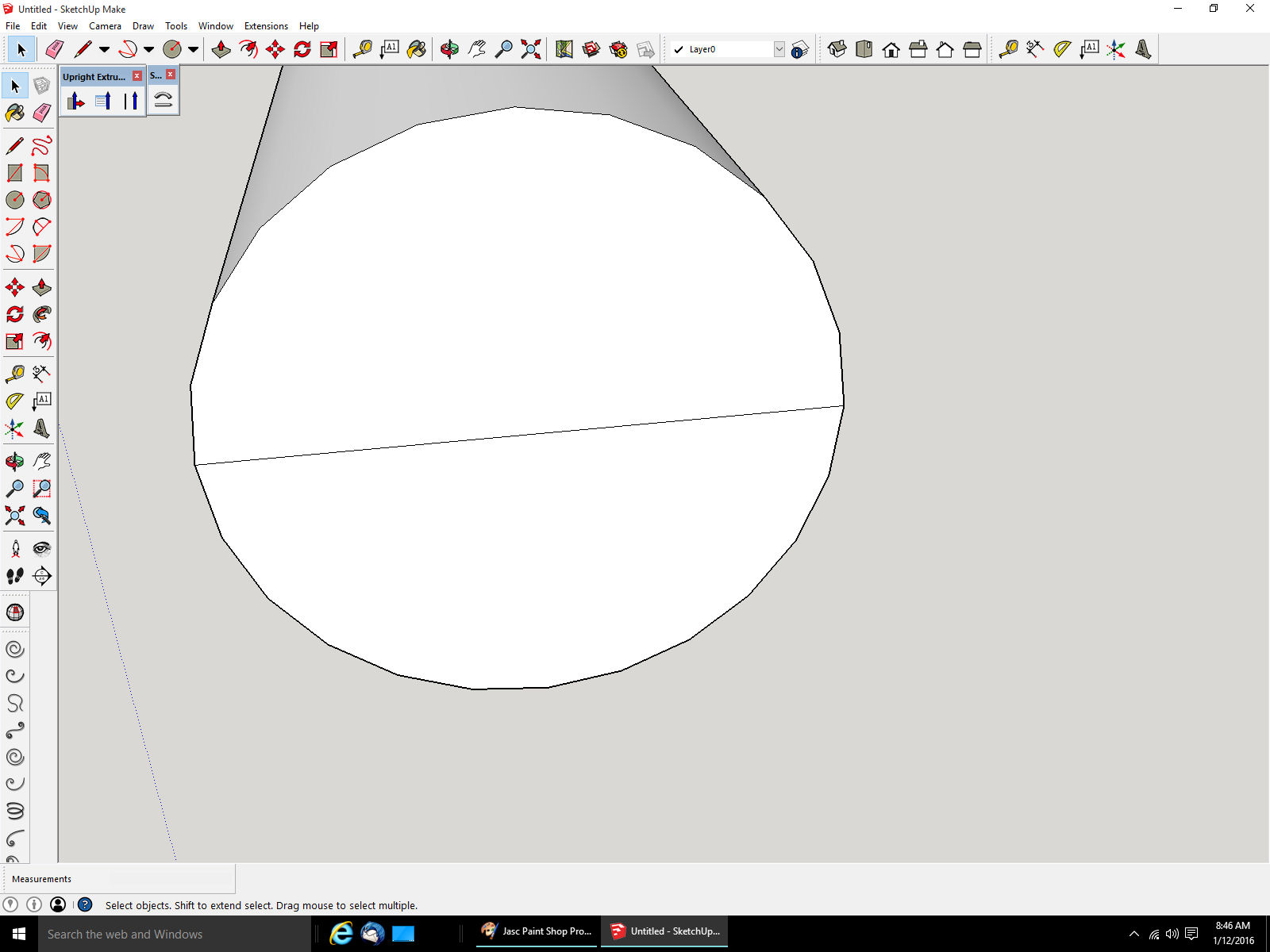
Part 05 B There is an option in the “View” menu – “Hidden Geometry”. This shows the lines that the Part is created from. You can see the lines that run the length of the cylinder, which is really a circle of flat walls, the boundary of which are the dashed lines. If I erase one of these walls you can see what I mean. By the way, the cylinder is no longer a solid part. It is just a collection of walls. To be a solid a part must be closed. This also happened when I deleted the top of the end to show you what was happening. To make the cylinder whole again, we need to restore the walls. Draw a line over one of the existing lines around the open area. This may also restore the top of the end, if not you can do the same to it by, either drawing a line over the line we drew earlier across the end, or by drawing from any point on the rim to any other point along the rim. With the end restored, this way it is now three surfaces, just delete the two lines to make it one surface. If you do this to some part on your drawing, to clean it up visually say, and some surfaces disappear, what you are seeing is not one flat surface but one made up of two or more surfaces, that are slightly different in orientation, like the side of the cylinder. Remember to check your whole drawing regularly for accidently deleted walls. Next time I will show some of the ways you can extrude a part, after that we will get back to the winch drawing.

-
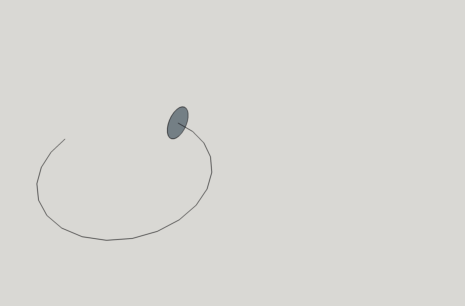
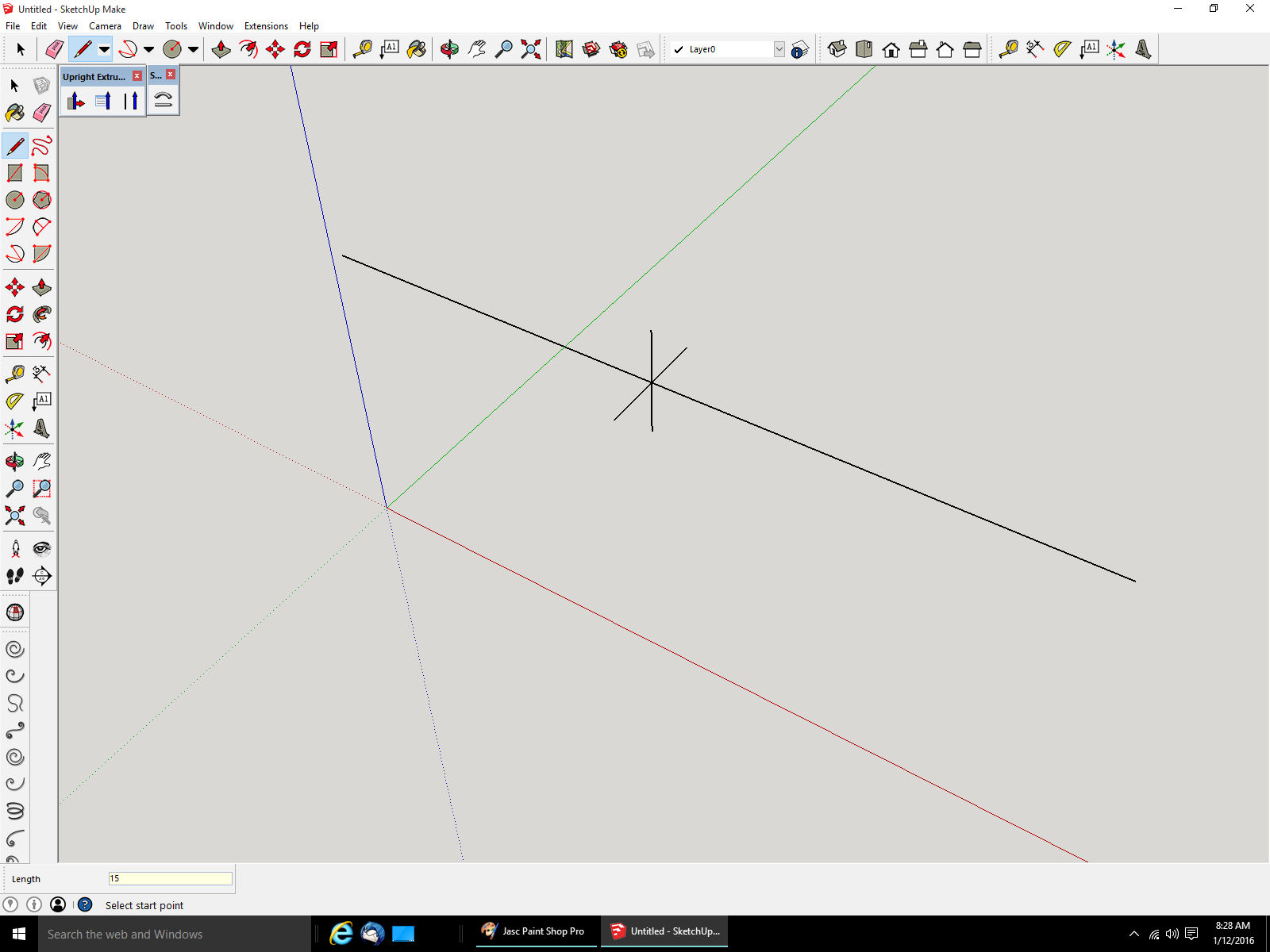
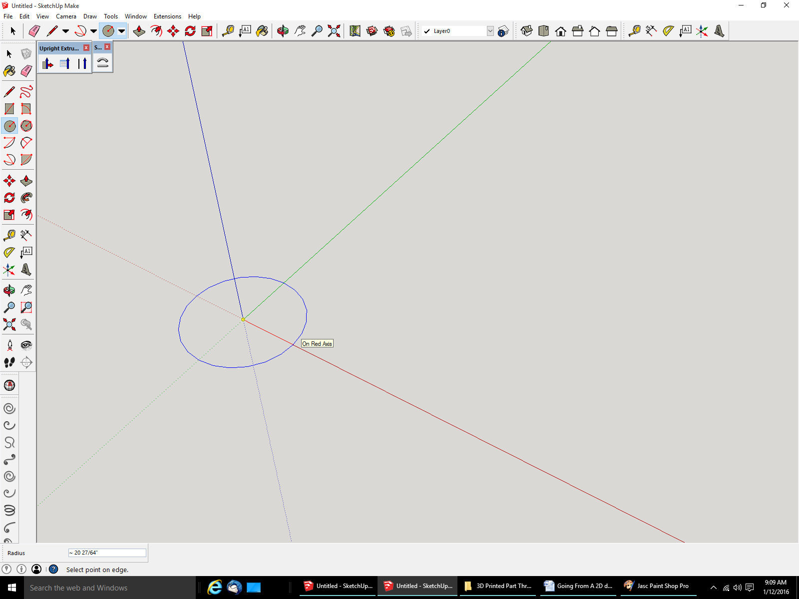
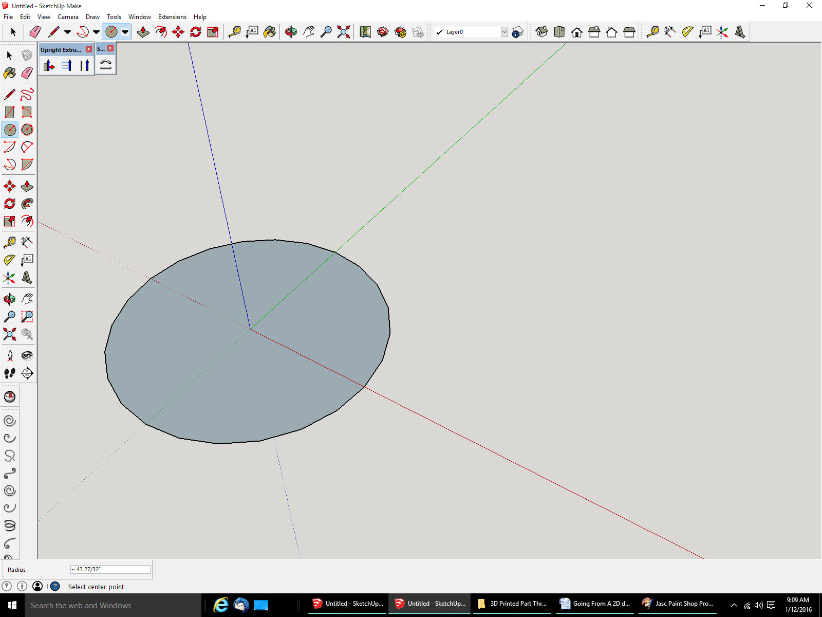
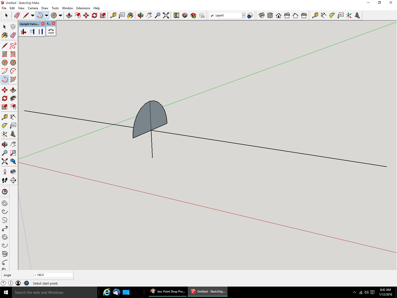
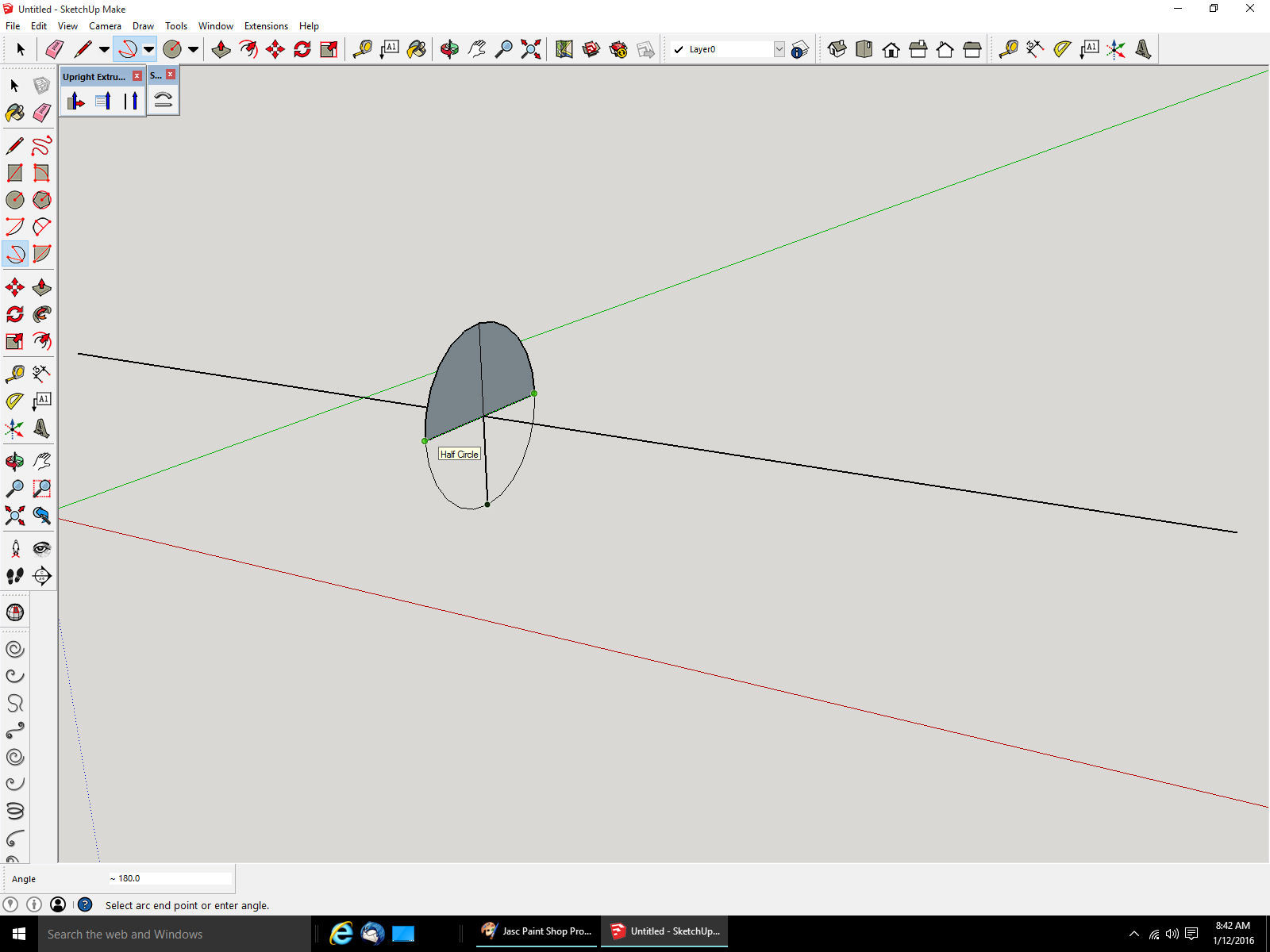
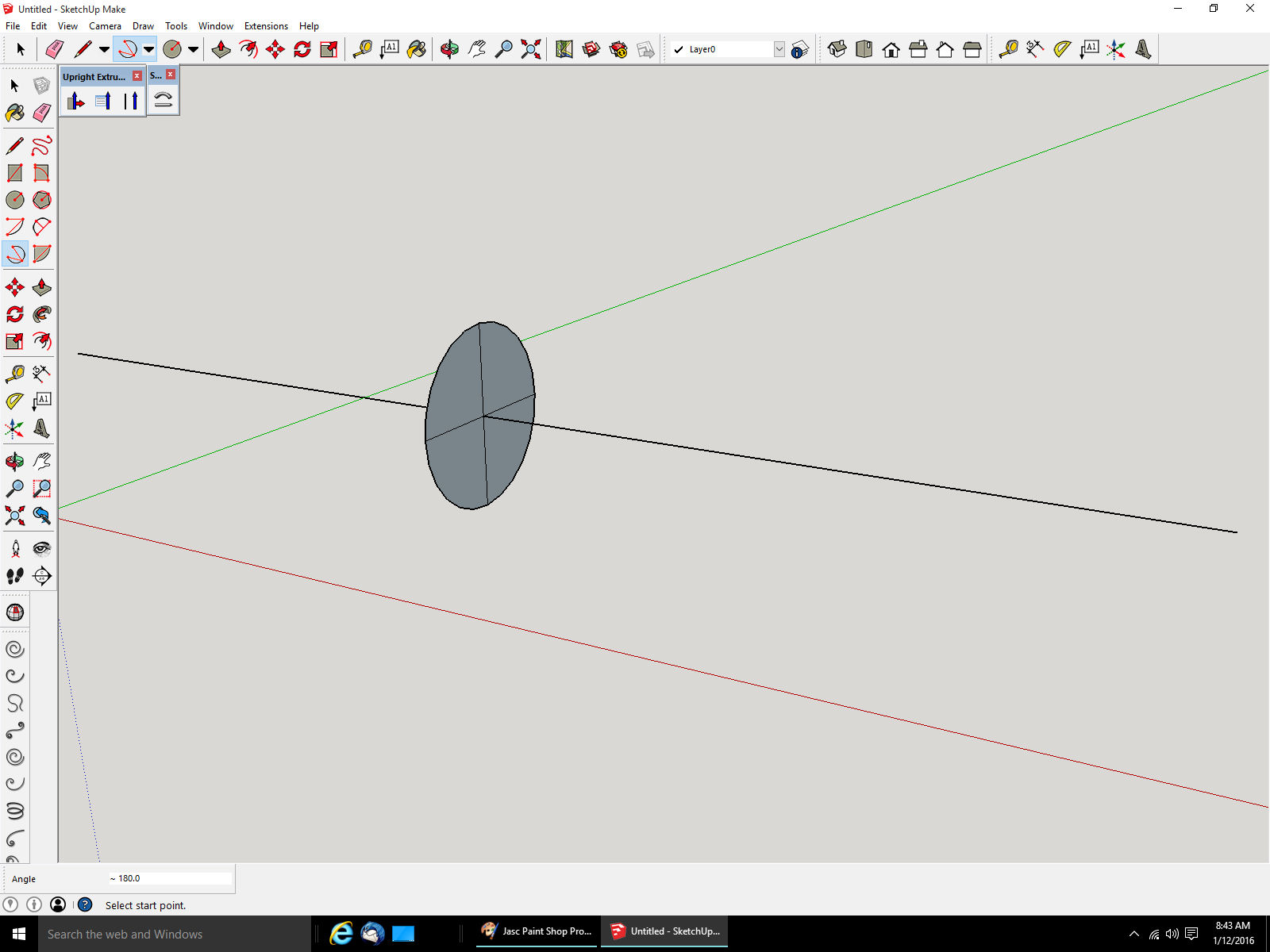
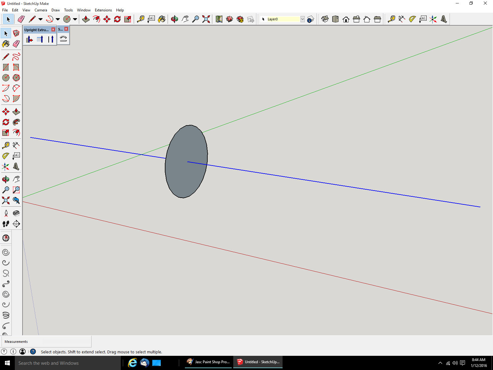
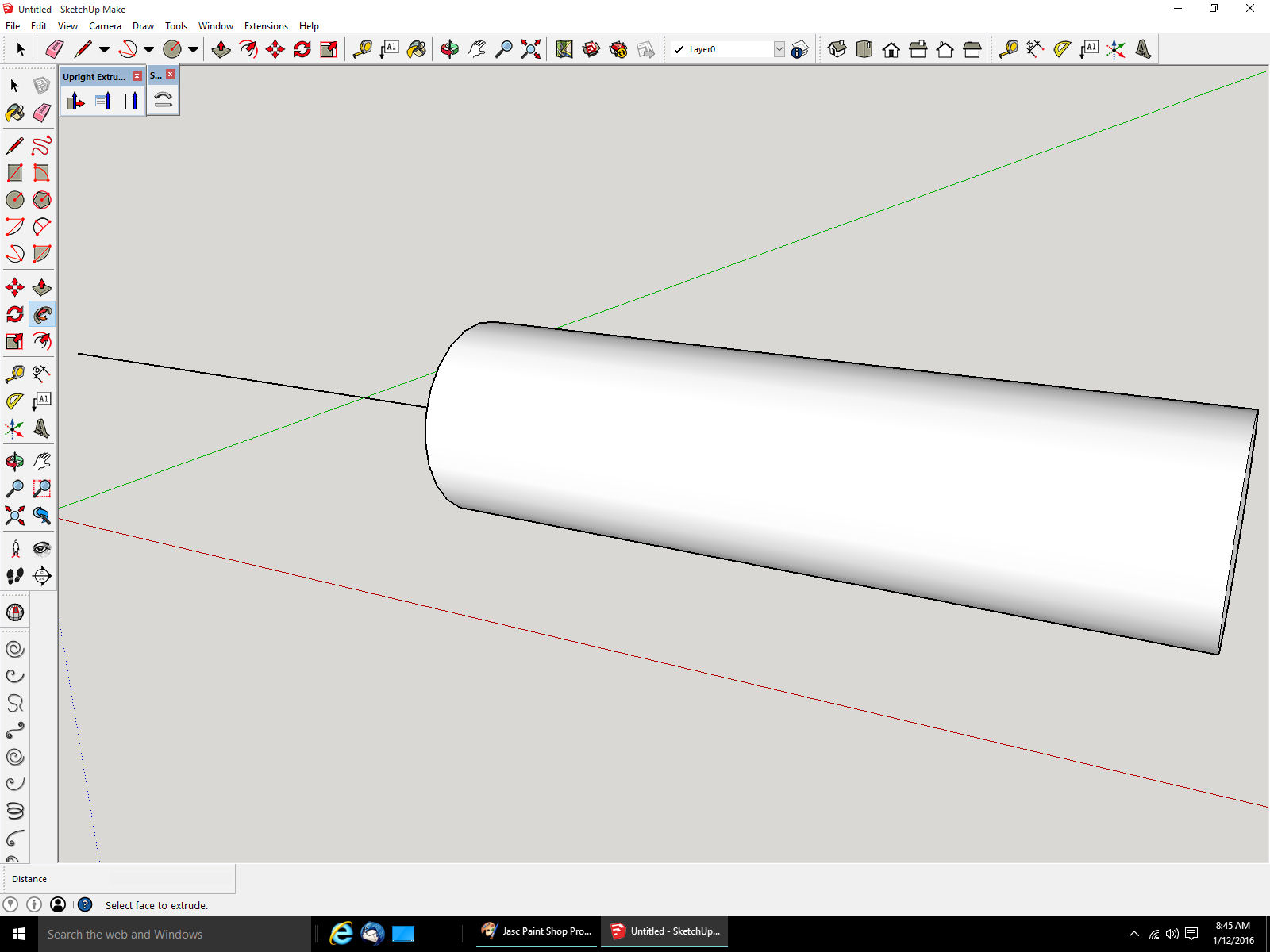
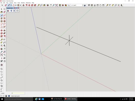
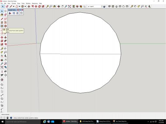
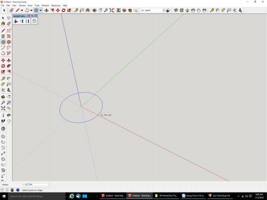
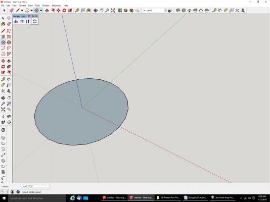
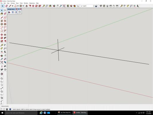
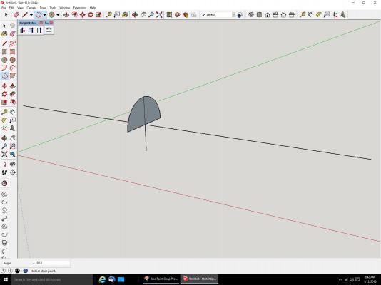
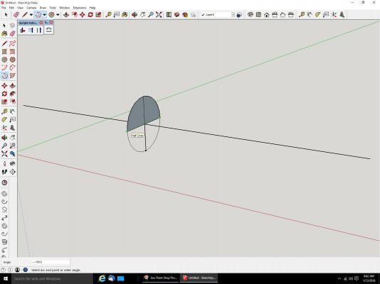
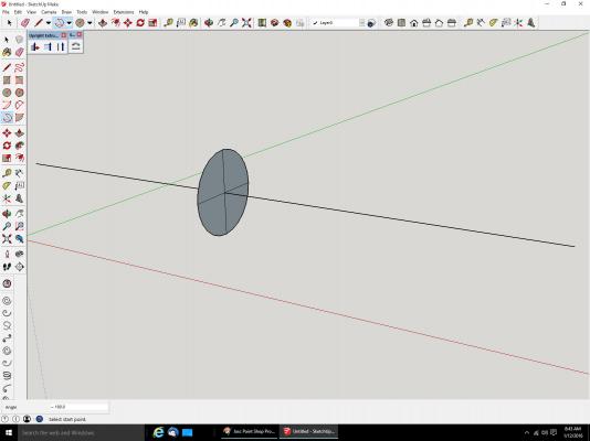
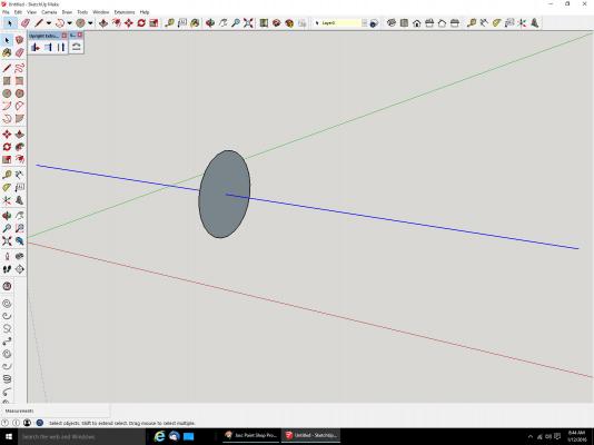
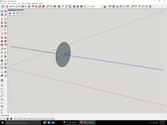
Going From A 2D drawing To A 3D Printed Part Part 05A I’m going, in this part, to show how one of these interior walls can accidentally be created. We’ll start by making a cylinder, that follows a line. Here is the line with four lines perpendicular to it, all the same length, and at 90 degrees to each other. Basically a cross. There are several ways to draw a circle, centered on a line. The easiest one is to use the “Circle” command that comes with SketchUp. You can see the icon for it at the left of the screen shot below. The trouble with using this, is SketchUp will pick one of the axis to be the plain the circle is going to be drawn in, and generally, it will be the wrong one. It most times will pick a circle that is in the XY plain. The pictures below illustrates what I mean. If you are drawing the circle on an existing surface that is parallel to one of the X,Y, or Z axis, it will generally choose correctly, but not always. These are pictures of drawing a circle with this command. This was the only axis that it would allow me to draw it on. To continue with showing how an interior wall can be created. We need a vertical circle. The way I use is to draw a cross on the line, then draw the circle using the “Draw – 3 Point Arc” command. I connect three of the legs, to make half the circle, then another for the other half. If your line is angled, this is the only way I know of to draw the circle, perpendicular to the angled line. The process is shown below. Line with cross drawn. Same as above, just looking at it a little closer. Top half of the circle drawn. Drawing the lower half of the circle. Note that SketchUp will tell you that this is a half circle. If the lines in the cross are not at 90 degrees from each other, or at least the same length in the same plain, the circle will not be correct, and you will not get this message. You can look for this to check your work. There are other ways you can still use to draw a half circle, but this is a good check. The circle shown above, is presently four different surfaces, one in each quarter of the circle, because the lines of the cross separate each from the other. We need to make it one surface, by erasing the lines. SketchUp will then combine them into one piece. Here are the lines erased, but this can cause a problem. For this example, I only want to create a cylinder to the right of the circle. With all the lines gone, the center line is all one piece, and the following steps would draw the cylinder in both directions, so we need to put one of the lines back. With this line touching the centerline, SketchUp breaks the line into two different lines, at the meeting point. Now you see only the right side of the line is selected. Now we will draw the cylinder by extruding the circle to a 3D shape, using the “Follow Me” command. Now let’s say we need to add something to the right hand side, centered on the circle. We need to find that center, so we draw a line down the center. By doing this we have completed a rectangle inside the cylinder, that SketchUp makes a wall/surface from. The sides are the one line we left on the circle, the centerline, part of the new line, and one of the lines that run along the cylinder. Remember it is really made up of several flat surfaces, and hollow inside. With part of the end removed, you can see the wall. See Part 5B for the rest of the post.
-
Found the problem, too many pictures for one post. I thought the limit was 16, guess its 15.
-
There seems to be something wrong with the site. It says that I've posted more pictures than I am allowed to. This is strange, as I have seen many logs of extreme length. I'll try again later.
-
Yes scale models can be made. I saw a video from a car show, where one of the car companies had a huge 3D printer, printing out a full size car body. A finished body was then sent over to a robot, that sanded the body to remove the ridges left from the 3D printing process.
-
Its like modeling, you learn as you go. I always hated the computer language classes (I was a programmer by profession), I did not like the set exercises. I always preferred to learn by applying it to something I wanted to do. Same here.
-
I do, I just don't print them! :-)
-
Now Hear This! Torpedo boat V108 model now available!
thibaultron replied to ccoyle's topic in Card and Paper Models
Never mind, did not notice the link in the post. -
Now Hear This! Torpedo boat V108 model now available!
thibaultron replied to ccoyle's topic in Card and Paper Models
What is the title of the build log? I searched and could not find it. -
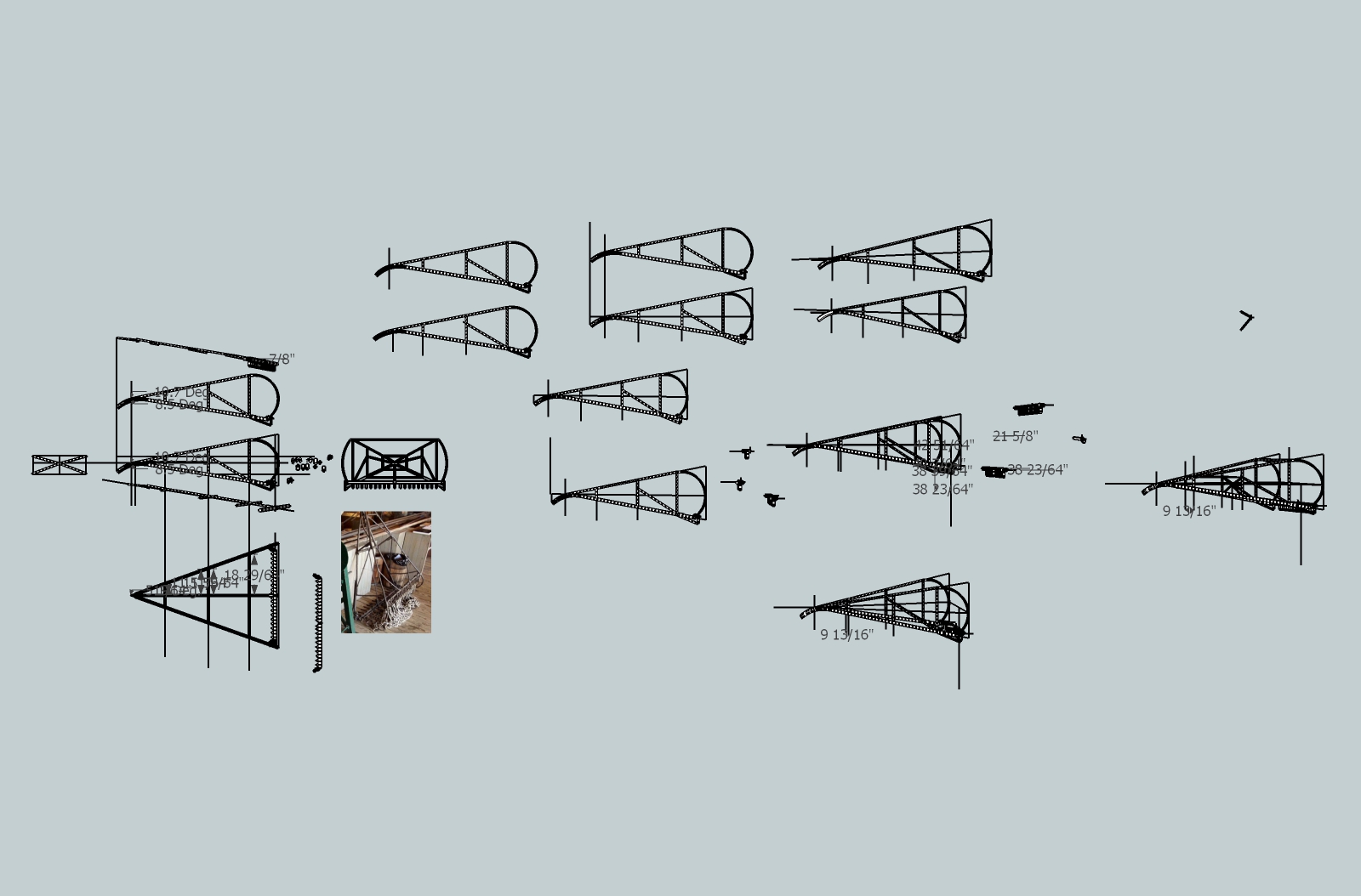
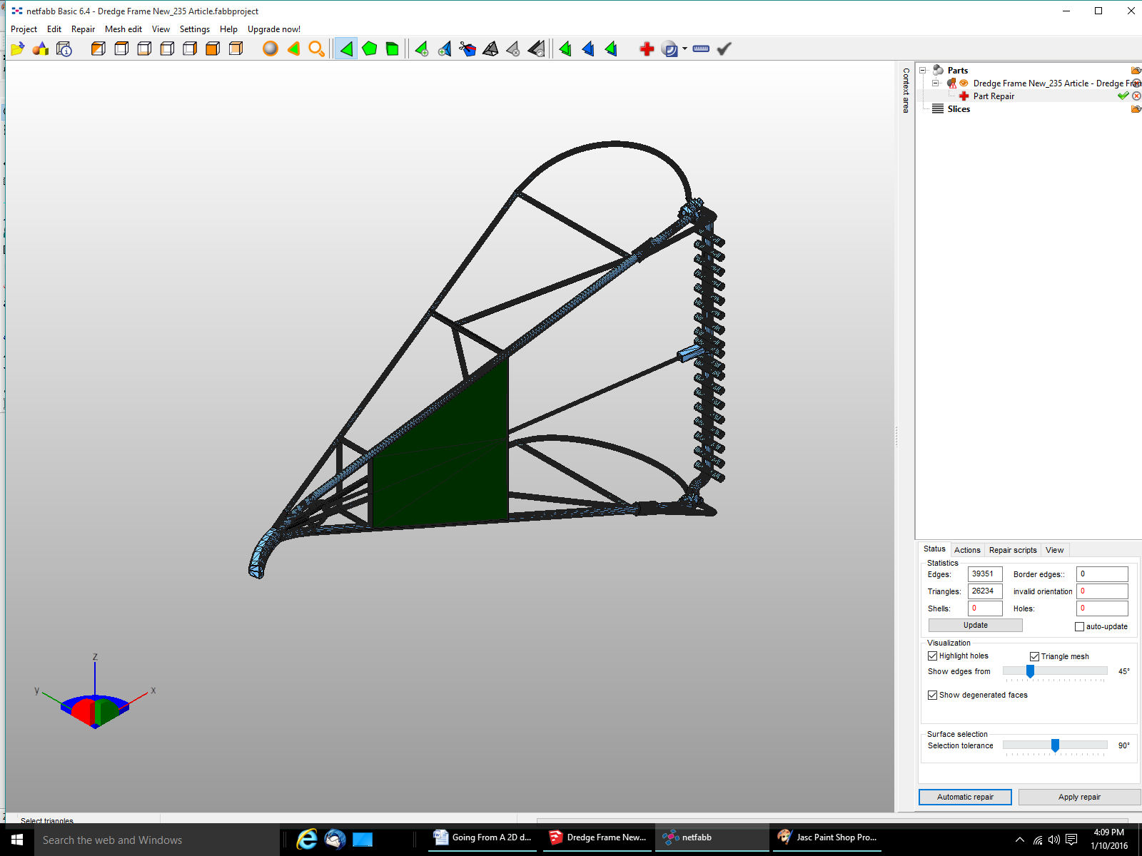
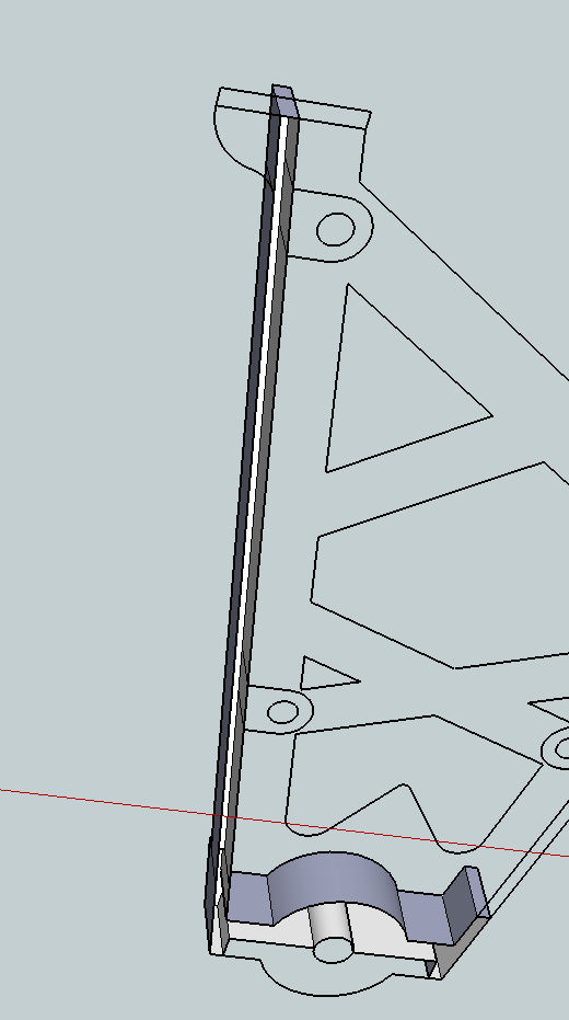
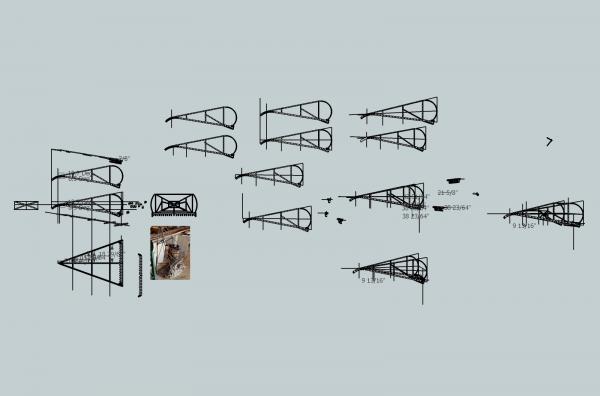
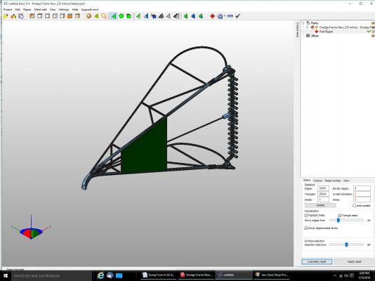
Part 04 There are some hidden problems that may crop up, in your drawing, that will bite you, unexpectedly. Not consistent ones in the program, but problems that can be internal to your part, and not visible, normally. The part that looks solid, is really a skin of flat surfaces, that is hollow inside. I will be referring to these surfaces either as surfaces, or walls. Sorry that’s how I think of them, though they are not the walls you think of in your house, or a wall drawn in the program. When you export the file to the 3D print type file, the program makes it “solid” (filled) as far as the printer knows. This type of output file is a .STL type of file. This is not the same type of file SketchUp uses to store your drawing, which is a .SKP type. The .STL is one of the universal file formats developed for exchanging files between different programs. Even if you don’t have Shapeways print your part, use their checking software often, as you progress. You may find there is a problem that requires redrawing a portion of it, maybe all. It’s better to check it frequently, so any problems can be corrected with minimum redrafting. Problems can include: sections or walls that are too thin to be printed, areas that do not really connect, small holes that would allow the part to “leak” if your part was hollow internally” and when filled water. An example of this would be two rods that cross, but have errors at the junction that leave some panels incomplete. If the rods were hollow and filled with water, it would leak out. These can be quite small, almost invisible unless you zoom in extremely closely. Another problem can be walls internal to your parts, that you don’t even know exist. They can be created by lines that go through parts, that perhaps you created when you drew in a new section of the part. This is an example of what I mean. The first picture is one of the dredge frame that the winch mentioned in the previous parts pulls in. This is one of the later versions of the drawing, when it is close to finished. Now we will zoom in to the hooked section at the front of the dredge. Looks good, but there is a hidden wall inside. In this case I knew the wall was in there, as I had drawn one side, then mirrored it and pasted them together here. What I found out later, was that it caused a “divot” in the 3D part right at the junction of the two rods, and the flat, in this view left area of the nose, when the 3D printer file was generated. Here is a picture with the end wall removed. Normally, of course, you would not delete the wall, but zoom into the inside of the part. If you keep zooming in closer you will zoom past this wall skin, into the inside of the part. You can see the gray surface in the center that is the hidden wall. In this view it has two parts. The line going down the center divides it into two separate walls. The right hand walls has been delete, in this picture There are, however still more walls inside this section. If we zoom in to the area where the rod is sticking inside, there are more walls to be deleted. There are three walls shown here that need to be deleted. You have to check carefully though, as there may be more you need to find. Zooming in closer, there is also a tiny wall near the junction. It is at the back center of the view. Sometimes you may also have to delete some of the interior lines. Experience will teach you what needs to be done, to correct some problems. You don’t have to do this all the time, most of these extra surfaces are harmless. If you do find a problem, though, this is one of the things to look for. As you are drawing your part, you will add lines to make part or as guides to placing them, and these can create interior walls you don’t know about. An example is a problem that I found during one of the test files I sent to Shapeways. This is a picture of the part in a late stage of producing the drawing. Looks good, but when I reviewed it a surface popped up that was not drawn in. This is a screen shot of the .STL file imported into a checking program I have on my computer. I run the file through this one, before sending it on to the Shapeways site. At least I do most times. Sometimes it does more harm than good. This program, and one of the checking features in SketchUp, will sometimes “Correct” a problem, by deleting the problem area! I’ll talk more about this in a later post. In fact, I was unable to use either correction program during most of the drawing of this frame, for that very reason. Not all problems these programs find, are really errors, they just think they are. As long as the Shapeways checks are good, you are fine. Anyway, the part looks good, until I run the correction feature! Suddenly there is a new wall/surface, on my part! As this is just a flat surface, with no thickness, the 3D printer cannot print it, and I would not want it to! What has happened is that while drawing the part, I unintentionally created walls inside the rods, that form a square, and thus this wall, as the software assumes that any lines that form a closed area, are meant to be a surface, not just lines. This surface probably popped into my drawing, and I deleted it, without thinking of why it was created. The correction software “fixed” the missing surface for me. The following pictures will show you where these walls are hiding. This is the side of one of the rods, close up. As I zoom in past the outer surface, we can see the wall, inside the rod. This shows the same area, after I deleted the wall. I had to travel through all the rods, and delete these surfaces. Below is an overall shot of the drawing at this point. There are lots of parts shown, but the one I’m working on, is the one at the right. The other parts are earlier stages in the drawing, or sub-assemblies that I am combining for the final part. I like to keep them as I progress, so if I make a mistake, I can go back to one of the earlier parts, and start from there. When I finish a major sub-part. I make a copy of it, and work on the copy, thus the progression from left to right as the drawing process goes on. The smaller parts are sub-assemblies I drew, then copied and pasted into the main assembly. When I go to check the latest part, I make a new copy of the file, say Dredge Frame_33 Test.skp. and delete all the old parts, leaving just the present part, I’m working on. The _33 means version 33, as I draw, I periodically save my work to a new version. Again this is so I can go back if I make a major mistake, or for some reason the file is corrupted, or accidentally deleted, or even if I need to see what I did to get to the present part in the drawing. Next time, actual drawing, and more pitfalls to look out for. Drafting for 3D is as much an art form, as a science, much like build parts for a model.
-
Had more success with the dredge frame drawing. It will now print out as one part in 1/32nd scale. I still have to add details, but most of it is done. Here are two pictures of the progress so far.
-
Still working on the dredge frames! They are kicking my A..! The frames are not that bad, but drawing them so they can be printed is taking a lot of trial and error. These are pushing the state of the art, due to the thin spindlely construction. I'm on drawing version, about 300 now. A version is not a complete redraw, just major points in changing the drawing. I've restarted from the original CAD drawing 3 times. The boxwood stock for the boom and mast are "In the mail", And the cheap numbered drill bits that I'm going to use for the winch rods, have arrived. It may be warm enough in the shop to paint this weekend, so I can prime the 1/64th scale winch parts.
-
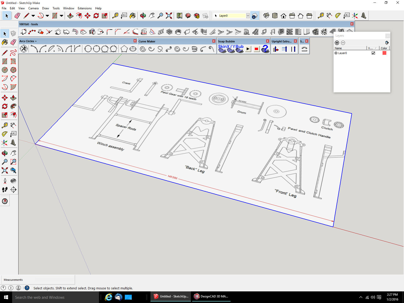
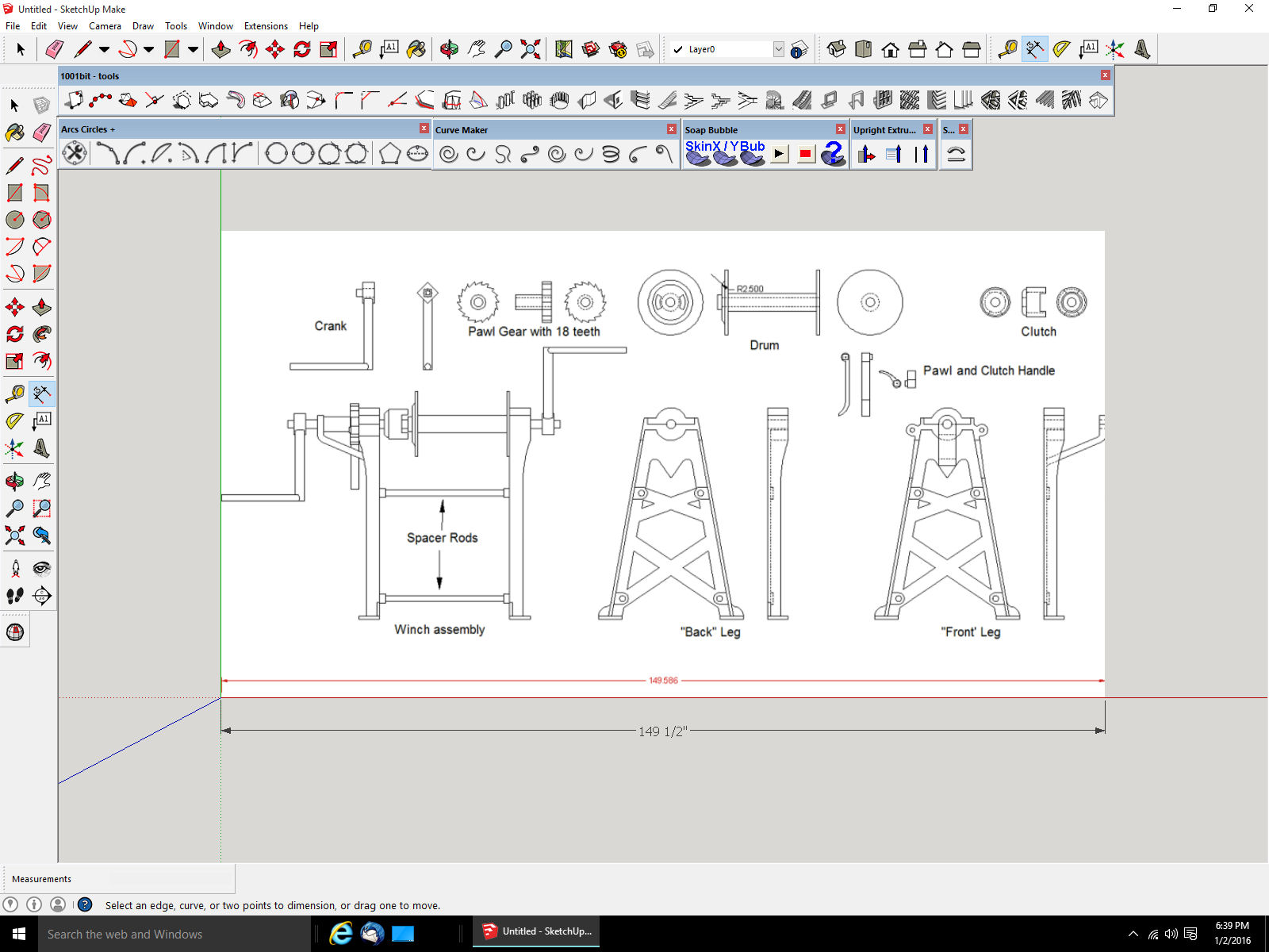
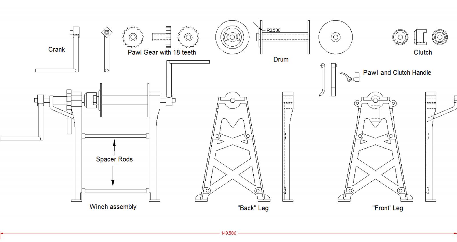
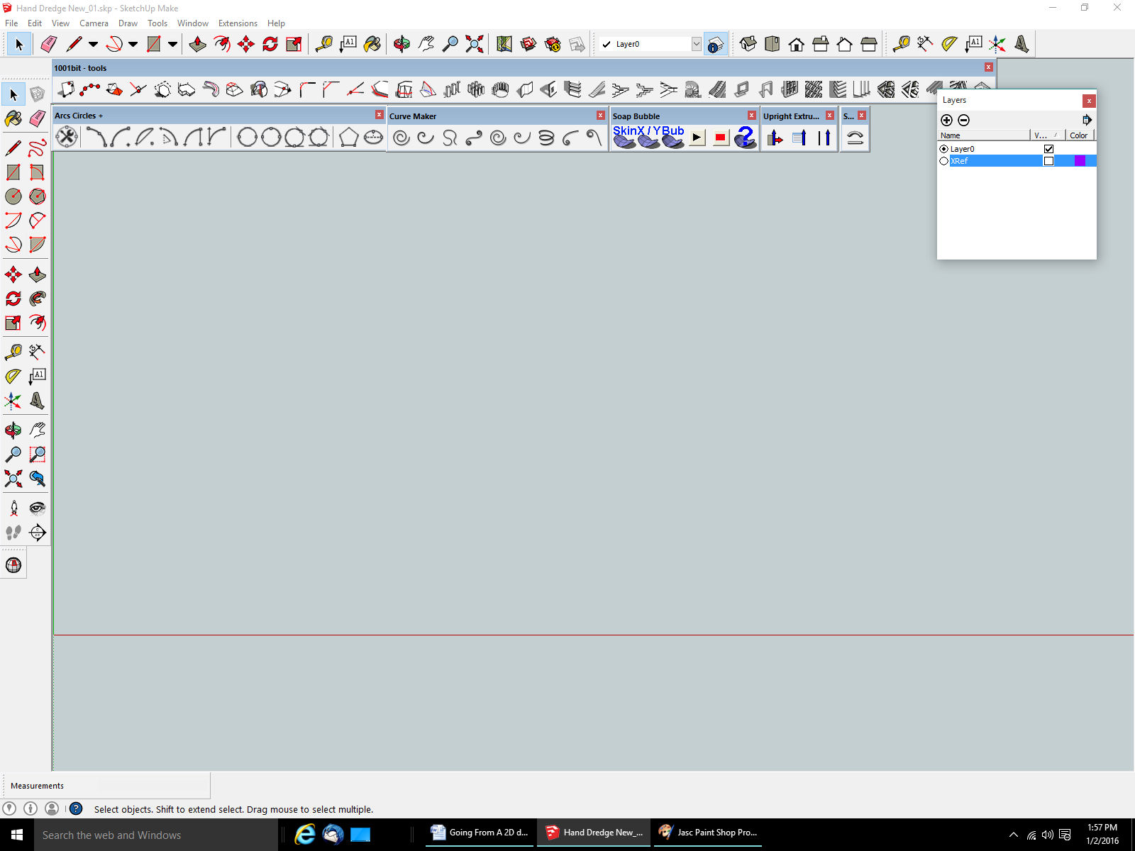
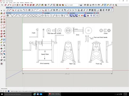
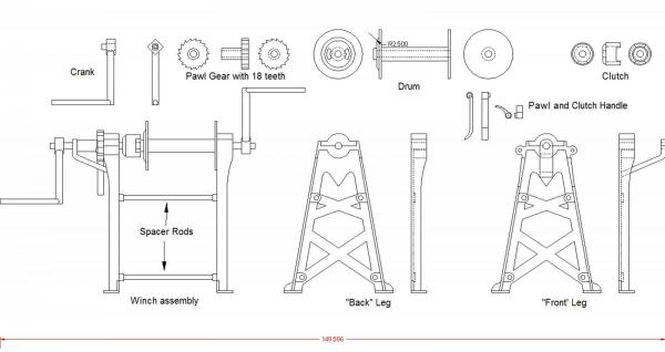
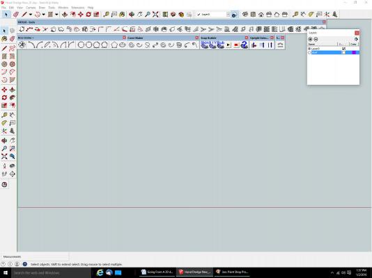
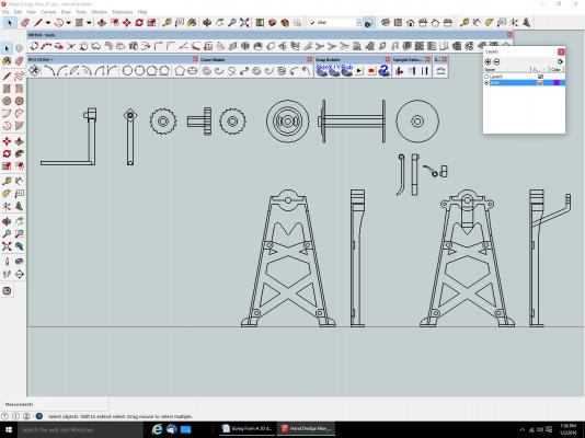
Going From A 2D drawing To A 3D Printed Part Part 03 Now importing your drawing into SketchUp. My drawing was imported as a DXF drafting file, making it easier to work with, but unless you have an extra $700 or so laying around, or know someone with the Pro version, you will have to import it as a picture(graphic) file. The latest version of the CAD program I use DesignCAD (v 25), I use V 24, can export the SketchUp file format, Others may be able to also. The DesignCAD v25 also does the STL file export, but SketchUp is easier to use than trying to do the 3D in DesignCAD, for many operations (years of experience in DesignCAD). Though both will do some things the other will not. SketchUp will allow you to enter absolute dimensional points, when drawing. So you can start a line, for example and have it drawn 2” long. The first and most important thing to remember. SketchUp will import the drawing/graphic into Layer 0. If you have imported a DXF drawing file, you will be highly tempted to use the lines in the drawing to continue. Do not do this!! Strange things came happen, and if you make a mistake, you have possibly lost your references to correct it. Some of these lines might be erased. Create a new layer, select the layer name and change it to something you will recognize as the layer not to draw on. I use “XRef”. Then set this layer to be the active layer (selecting the little dot by the name). Unfortunately if you import a graphic file, SketchUp will not treat the lines on it as real lines, making tracing a little harder (It will not indicate the ends of the lines). You can, however, import it to scale. Have a line drawn to whole width of the drawing, that you know the length of. When importing select the origin, then when you go to place the second point to set the drawing size, enter that value. The second point will be X away from the origin, and your drawing will be to scale. Graphic of winch drawing. For this example I shortened the entered number to 149.5” rather than the 149.586”, but it would have done it, if I’d put the full dimension in. When I saved this image from my CAD program I made the image 5000 pixels wide. If you select the icon with the “!” in a circle to the right of the box that shows the presently active layer, a list of all the layers will be displayed. Now select all the things on this layer, right click, select “Make Group, then Right Click again and Select “Lock”, this prevents further editing of your imported reference drawing. Set the active layer back to Layer 0. A general note about layers. If possible do all your drawing on Layer 0. I don’t always follow this rule and it can cause problems. If you have an object on say Layer 4, then switch back to Layer 0 and continue adding to that object, part of it exists on Layer 4 and part on Layer 0, making some operations difficult or confusing when you turn off a layer for viewing, and find part of your object disappears. The only way to make the part exist on a Layer, when this happens, is to delete the layer and select the “Move contents to the Default layer. This will move everything on the layer being deleted, to Layer 0. I should follow my own advice more often. SketchUp also seems to have problems with moving things off of a layer (other than 0) once it is on that layer, and objects that are strewn on more than one layer, can’t be moved at all. You can now start your drawing by tracing over your reference lines. Unchecking any layer will make it invisible, checking it, of course, will make it visible. This is a view of what happened when I extruded a shape directly from the imported drawing lines. It extruded without the “bottom” face. This can be corrected, but it may cause problems later. A good habit to get into is regularly checking that some operation, mainly deleting something, does not cause this same thing to happen during your drawing operations. You can accidentally erase a face on an adjoining piece, while trimming another. I regularly save to a new version, while doing the drawing, especially if I’ve just completed, or will be starting a major change (completing a part, doing a major change to a part). For example I’m going to “drill” a hole in a part, I’ll save the present drawing, then save it again to the next higher version and do the drilling operation in the new version, in case I goof. Sometimes I’ve had to go back several version, when I discover I’ve done something that made changes, I did not notice, or think of a better way to do what I’m trying to draw. As an example if the present file name is: Dredge Winch_21.skp, the next version would be Dredge Winch_22.skp.
-
The plastic I had them printed in was the "Frosted Extreme Detail". The pricing is $5.00 setup, then based on the volume of plastic used. The price was the same whether I had all the parts on a sprue, or separate, so I choose individual parts, to save on trimming. The exception was the nuts in 1/32, I had to sprue them, as they were too small individually to print. In 1/64th, I had to sprue more of the parts. I discuss this more in my Carrie Price log. I'm presently drawing up a dredge frame similar to the one sitting next to the winch, in the picture in the first post. I will be able to print it out with scale rod thicknesses in 1/32 (smallest rod 7/16" scale). In 1/64, I will have to go to 3/4" minimum thickness, but it will still look better than I could fabricate, and will be round sections, not flat as they would be if I went the photo-etch route.
-
For 4 of the 1/32nd winches, about $20. For 4 of the 1/64th, about $10. I had 4 of each printed, so I can mess up a couple. I've already lost one of the crank handles, it flew off into the same place those drier socks go.
-
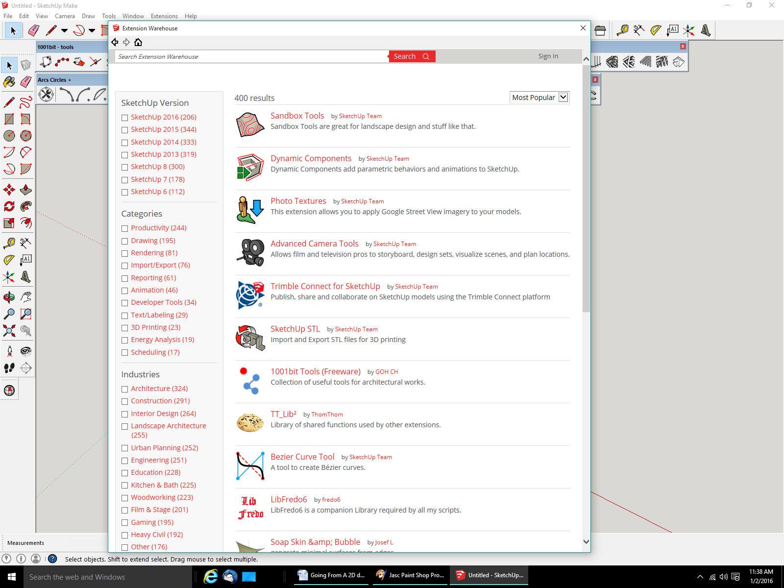
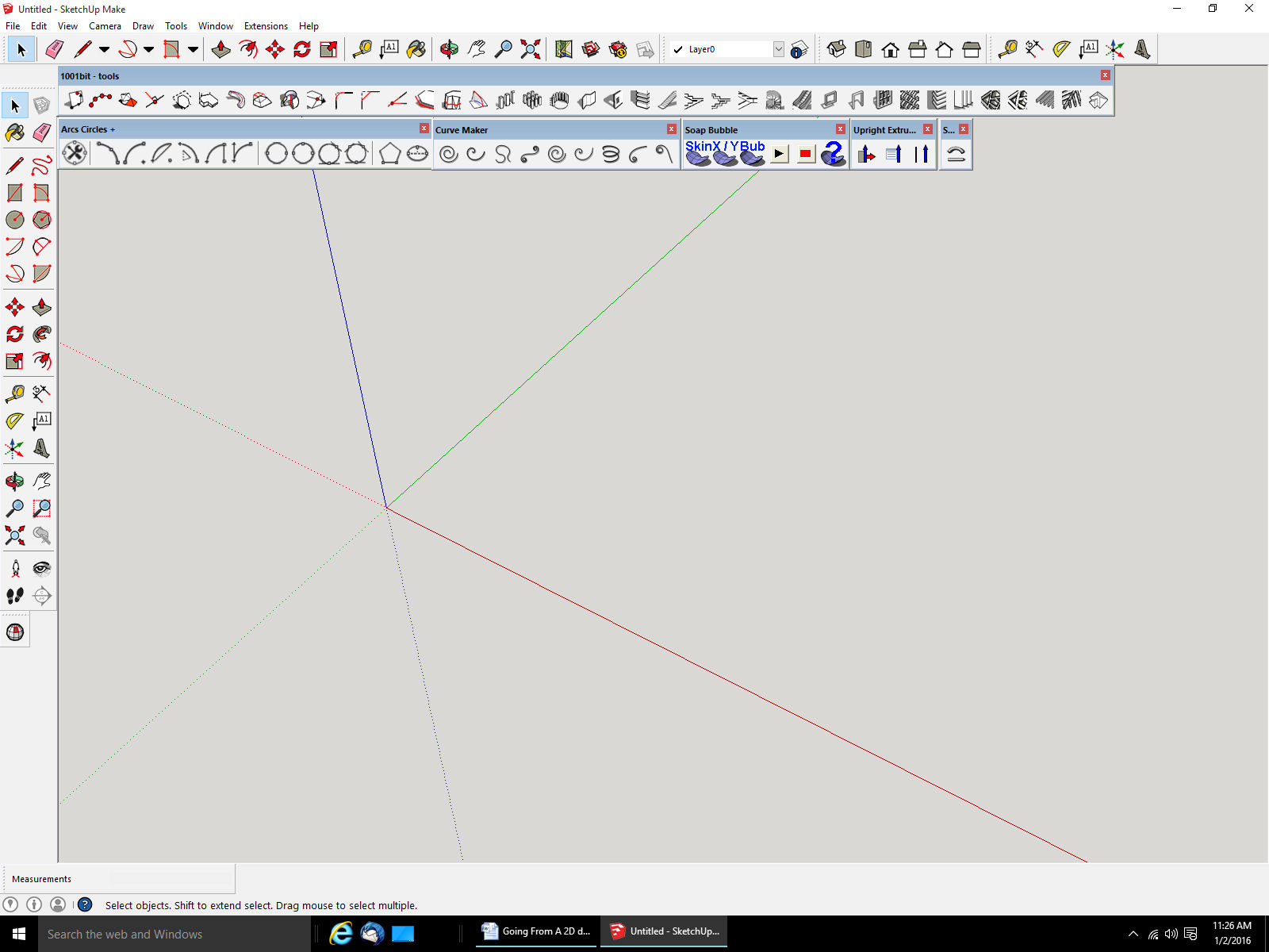
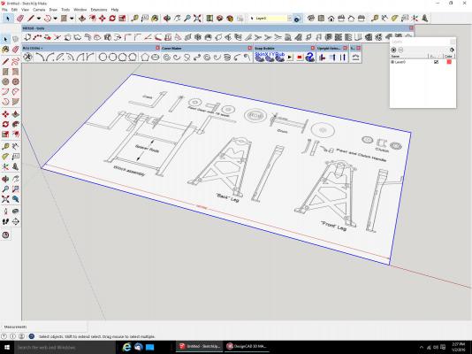
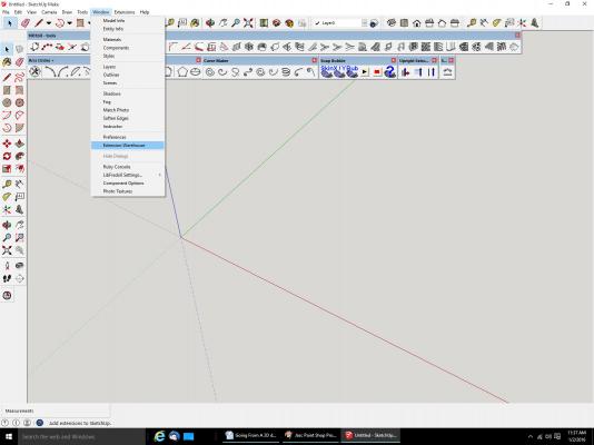
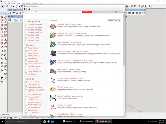
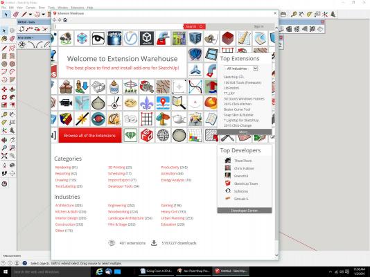
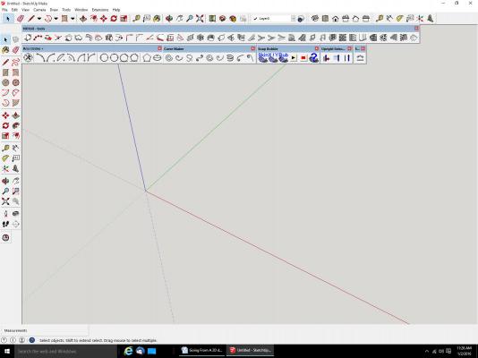
Part 02 I’m not going to try to give a step by step tutorial, but rather some specific steps and “Things to watch out for” help. Firstly here is a shot of the SketchUp screen. I’m using the 2015 version, they have released a 2016 version, but I did not want to have to reload the Extensions. The Red, Blue, and Green lines represent the X, Y, and Z axis respectively. The top most and left hand most icon bars are the standard SketchUp drawing commands. The lower two icon bars are commands for the Extension programs I mentioned last time. The icon at the very bottom left, is also for an Extension. You can access the Extension Warehouse from the Window menu, not the Extensions menu, that one shows a list of most (not necessarily all, hey it’s a free program) of the ones you’ve added. Selecting the Extension Warehouse item will bring up this screen You can select either the More button at the bottom of the Top Extensions window, or the Browse all of the Extensions button. I selected More and the following screen is displayed This is a list of the extensions available from this site. There are other sites that offer many more. A Google search will find them. You can scroll down the list to find the one you want. As you go down to the bottom, more titles will be loaded. If you open an extension, it will have a button to install that one. If you just go back to the list, the list will be displayed starting from the first item again, a pain. Read the descriptions, some will have instructions on using the Extension, as well as listing any other Extensions that may have to be installed before that one. Many require you buy them, but the ones I use are free ones. The Extensions I used for this drawing are: Arcs Circles Eneroth Upright Extruder CleanUp3 (not CleanUp, or CleanUp2) Rotate 90 Shapes SketchUp STL (Used to create the type of files to send to the 3D printing company) If I find any others I used, I will list them as I remember them. The SketchUp site, has several tutorial videos, and there are many others on YouTube. I’m going to assume you have some practice with the program. Watch the tutorial videos and get some practice. Next time getting your drawing into SketchUp.
- 112 replies
-
- 10
-

-
I started the log, it is called: "Going From A 2D Drawing To A 3D Printed Part Tutorial"
-
For those interested, I've started a log on the process I went through to go from the 2D drawing to the 3D part. "Going From A 2D drawing To A 3D Printed Part Tutorial"