thibaultron
-
Posts
2,953 -
Joined
-
Last visited
Content Type
Profiles
Forums
Gallery
Events
Everything posted by thibaultron
-
 After I get my initial frames done I lay them out in 3D and check the flow of the lines. I can't show an example, my main computer power supply died, and it has most of my files on it.
 -
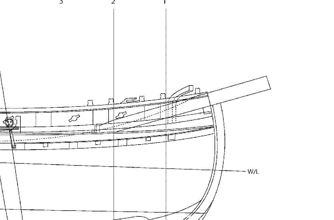
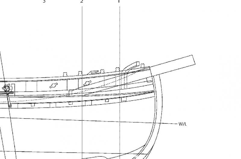
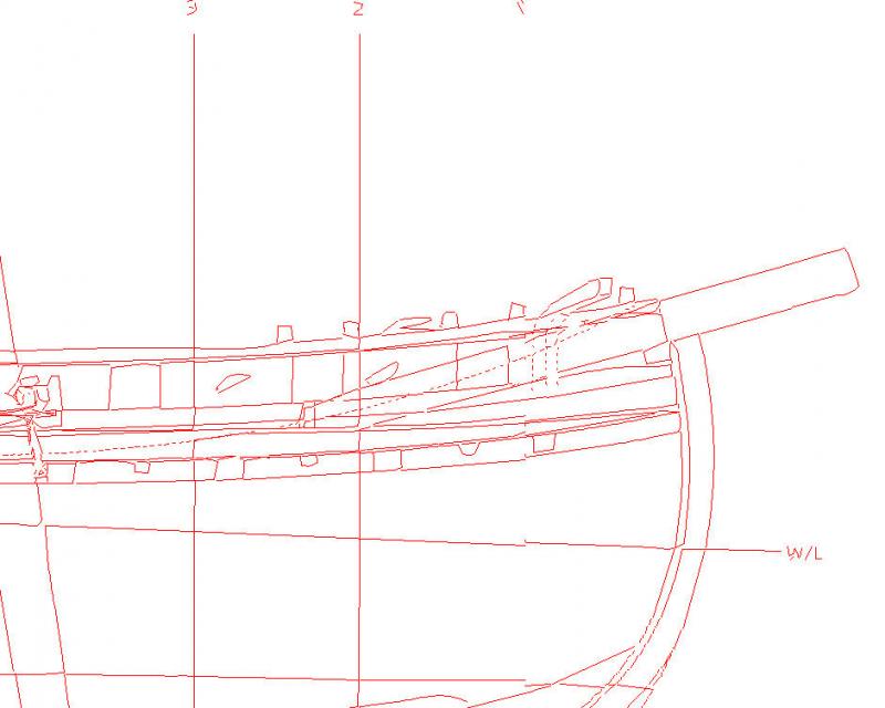
As an example, I took a section of a plan showing the drawing imported as a graphic, and the traced results. (Yes a publicly distributed plan). The drawing shown is fairly course, I normally scan the plans in at 300DPI. As you can see, the traced drawing is not in any case, in any way useful. This is the type of result any of the Tracing programs, free or purchased, will give you.
-
On a safety note, for those who don't know: Never use oil or grease of any kind on or around the O2 bottle threads!!! Learned this in a welding class. The teacher said it would go Boom!
- 749 replies
-
- 5
-

-
- albertic
- ocean liner
- (and 2 more)
-
Stop!! For all intents and purposes, NO, tracing software is usable for drafting! None! Later today I'll show you an example, I have to go out for the day now. The only viable way to go from JPG, PDF, etc. is to import the drawing and trace over it.
-
Fokker Dr.I by Torbogdan - FINISHED - Model Airways
thibaultron replied to Torbogdan's topic in Non-ship/categorised builds
I called them, then as they requested emailed the info on the parts I needed. Took only about a week to get the replacement parts. -
I'll have to look into the danta. I have several kits that use mahogany for the original mahogany parts, and the grain is way too course for the model.
-
CAD software
thibaultron replied to cog's topic in CAD and 3D Modelling/Drafting Plans with Software
Just to add more confusion, I recomend the 2016 version of DesignCAD 3D. It runs $70 to $100. There are several sites that offer a $30 discount to the $100 list price. I've used various versions for over a decade, and have been satisfied with it. The 2016 version can input and output files in the SketchUp format. This is a great feature, as only the Pro versions of SketchUp can import AutoCad file formats. Now I can go directly to SketchUp. Don't discount the usefullness of 3D capability. I generaly take my 2D drawings and use the 3D to "build" the model and check that everything lines up. This really comes into it's own when trying to draw from distorted, or partial plans. I have a tutorial on going from 2D to 3D drawings on the forum. That tutorial is going from 2D DesignCAD to 3D sketchup, should you want to make parts for your models. -
CAD software
thibaultron replied to cog's topic in CAD and 3D Modelling/Drafting Plans with Software
To run AutoCAD (mine is 2002) on Windows 7, or 8, or 10, you need the Pro version. It will not run on the any of the Home versions. I have run it on my Windows 10 Pro 64, with no problems. -
You might try Model Expo, they have a kit for the Morgan.
-
I have them also, I got them years ago, from the Smithsonian.
-
Reading further in "American Ship Models and How To Build Them" I found another interesting tidbit about Bugeye and Skipjack rigging. The deadeyes on both boats are setup with a much larger gap than an earlier type boat. Accourding to the book this large gap was to increase the length of the lanyards, to counteract the rigidity of the wire shrouds. This was in the section on the Bugeye Edith Todd, built in 1901. The Bugeye was a two masted boat, used for oystering before the advent of the skipjack. The Bugeye was sometimes referred to as a "Three Sail Bateau". The skipjacks were "Two Sail Bateaus". An interesting note on the Bugeye - The lower hull was built from several logs that were carved to shape inside and out after they were joined side to side, basically a large dugout canoe! The upper portion of the hull was then built up further with planking. The idea was to give a thick lower hull that would hold up to an accidental strike of the oyster beds during dredging.
-
How Realistic Can One Make Sails?
thibaultron replied to Julie Mo's topic in Masting, rigging and sails
I think it looks quite nice. For stitching perhaps printing the stitching lines on the paper, before gluing the panels? Obveously not on this finished sail, but on your next one. -
I found my other Skipjack book, but they do not say anything about the rigging materials. It is a nice history of the boats, with general details of construction, but no real modelers type info. Did talk somewhat about some of the tricks they used to hide illegal features. Some areas restricted cargo volume, so they would put in false bulkheads or move a bulkhead to make the cabin larger, then remove or move them after the inspection.
-
I'll find the more definitive book in a couple days. From "American Ship Models and How To Build Them"; It says that wire rope replaced hemp for standing rigging about 1860. Their instructions state that 3/4" wire rope was used on the skipjack Carrie Price for the shrouds, and 1/2" for the balance of the standing rigging. Hemp was used for the running rigging.
-
Certainly. I'll have to find the book, its buried, but I know the general location.
-
I have a Skipjack book around here, I'll look it up.
-
At the time skipjacks were built, they would have used wire cable standing rigging.
-
Fokker Dr.I by Torbogdan - FINISHED - Model Airways
thibaultron replied to Torbogdan's topic in Non-ship/categorised builds
Get a replacement! That policy is one of their big selling points for me. -
Are you building from a kit or scratch? Which Skipjack? I may be able to help.
-
Looked up the book A History of English Sea Ordnance, guess I'll have to pass on buying one. $300 to $400 US, too rich for my budget!
-
MS Fair American rigging plan leaves alot to be desired.
thibaultron replied to JPAM's topic in Masting, rigging and sails
Ships In Scale also sells a CD "Progressive Building" that has a practicum on their former editors build of the her. -
Thanks!!
-
Here is an interesting video on adjust a band saw blade. He uses a technique different from any other I've seen.
-
As long as the first outlet in the string is a GFI, the rest in the string will also be protected. The outlet GFIs are, if I remember correctly, much cheaper than the breaker ones.
-
I used Vallejo black on my cannon diorama. I brushed it on, but airbrushing would have been better. you may be able to chemicaly blacken them, depending on the type of metal. There was a thread on this earlier.