thibaultron
-
Posts
2,951 -
Joined
-
Last visited
Content Type
Profiles
Forums
Gallery
Events
Everything posted by thibaultron
-
 Thanks, for the help!
 -
In the past I have had metal lathes. I always protected and lubed them with various oils. Now I have a small one that I will be using mostly for wood and plastic parts. Lube oils and wood make a bad combination, as the oil would invariably end up on the wood. If any of you have lathes what do you use to protect the sliding surfaces from wear and rust?
-
Tadeusz: What do you use to prtect your lathe from rust, and do you lubricate the sliding surfaces, if so with what?
-
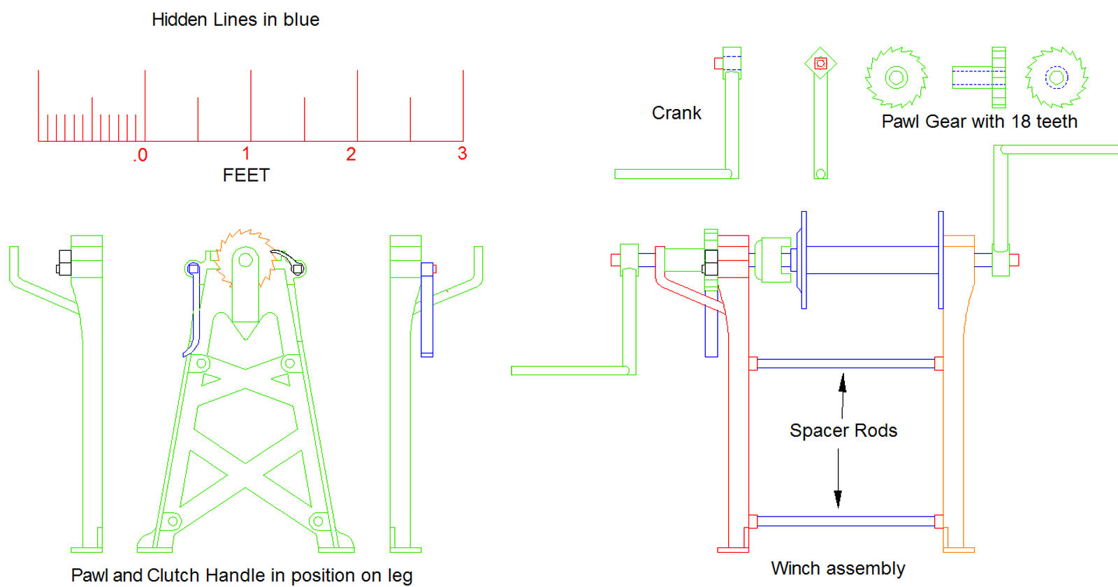
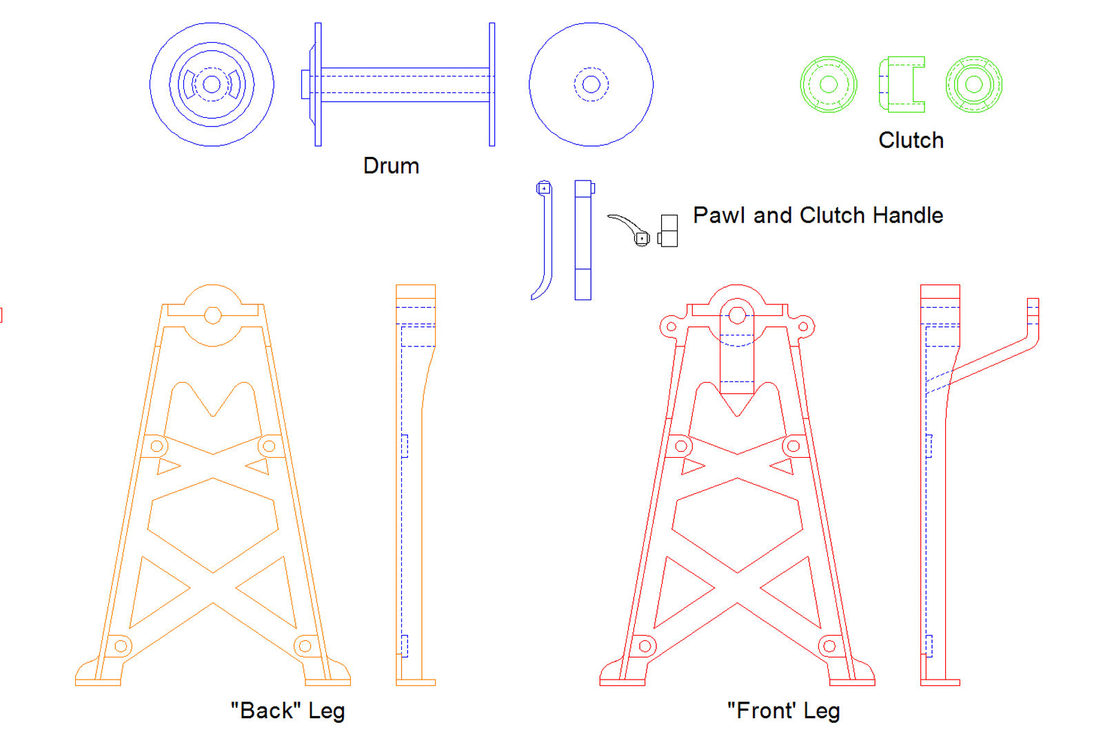
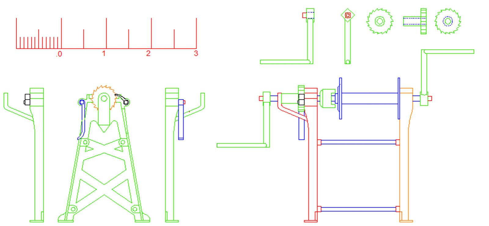
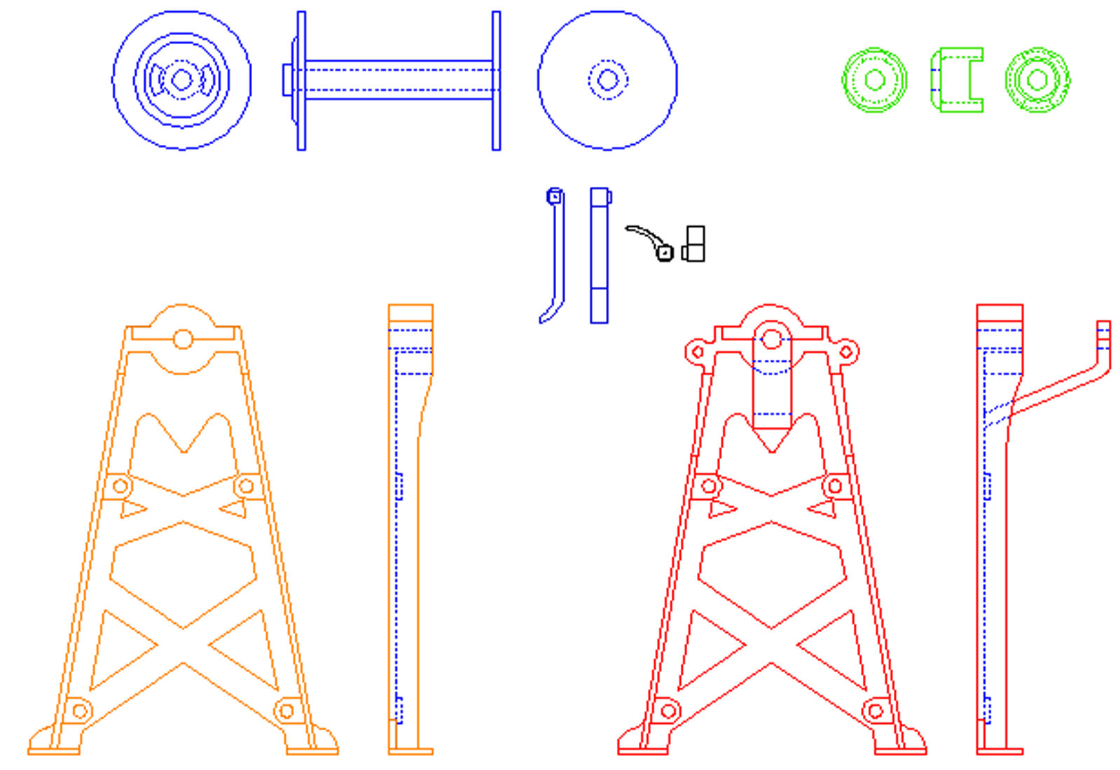
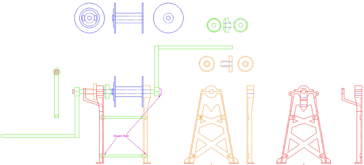
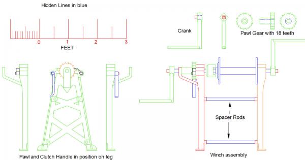
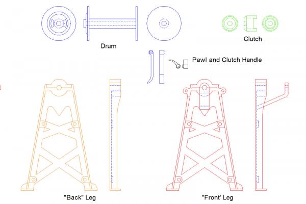
Here are the drawings with labels, to clarify the construction. I will not be posting a 3D drawing. My CAD program leaves lots of lines that should be "hidden" in the 3D drawings, and it takes 10 to 20 hours to erase them from the 2D views. I will be using SketchUp to do the 3D drawings, so that I have the option to send this out for 3D printing. First I have to learn SketchUp though, so it may be a while.
-
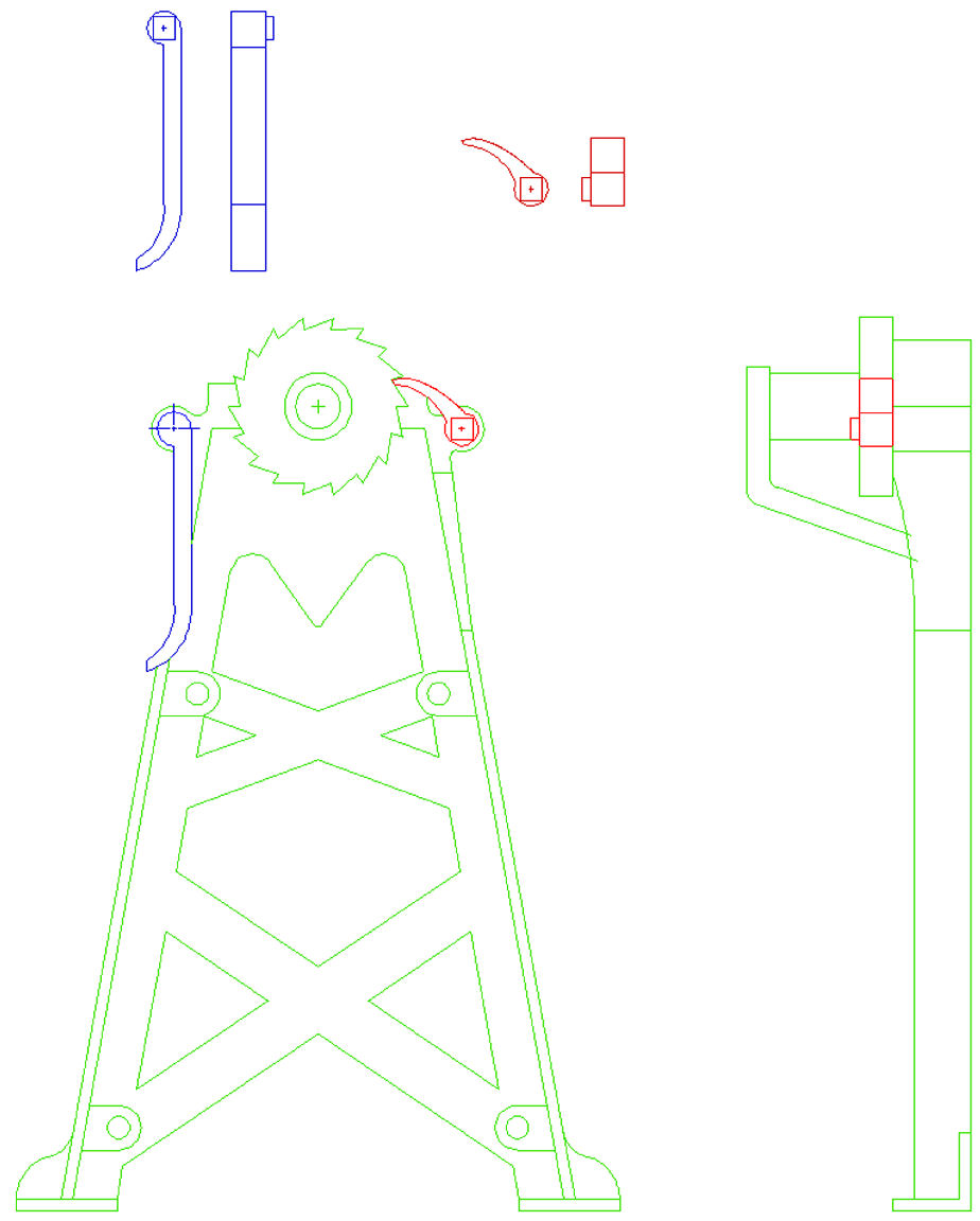
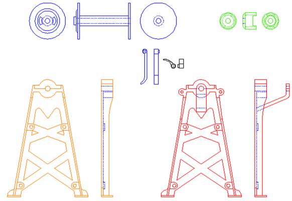
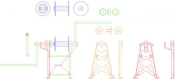
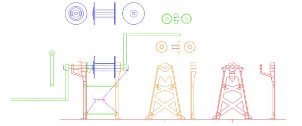
Part 24 Finished the 2D drawing of the dredge winch using the measurements Mahune posted. In the original drawings I assumed that the width of the legs was the same as the length between them, a square footprint. With the new measurements, this made the legs quite clunky, and squat looking, not like the spindly legs shown in other photos. So for this drawing I just rescaled the legs to 33" between the base and the center of the axle. The legs looked better this way. I did redraw the legs so that the edges were on reasonable inches and fractions likely to be used at the time. ie. 23 1/4" (24.25") as opposed to 23. 234". The legs had been drawn this way, but when rescaled the measurements got funcky. The rest was redrawn per the new dimensions. Here is the drawing. I broke it up into 2 pictures for better viewing. The scale of the two drawings is not the same, as I was trying to get maximum size per drawing within the 1600 X 1200 pixel site limits.

-
Dang! I wish I had $2500, though I live 100 miles from the ocean, so it might be a little hard to sail her.
-
Nope, proportions are off to much, will have to redraw most of it. I love modeling, I love modeling, sigh.
-
Thanks for the info. Looks like I have some redrawing to do, but I think I got it close in most proportions. For my drawings I assumed 36" for axle height, 27" for the base length, and 15 for the drum dia. Now I can get it closer using your dimensions. CAD is sometimes a pain, but a lot easier for making corrections.
-
Measurements would be greatly appericated!
-
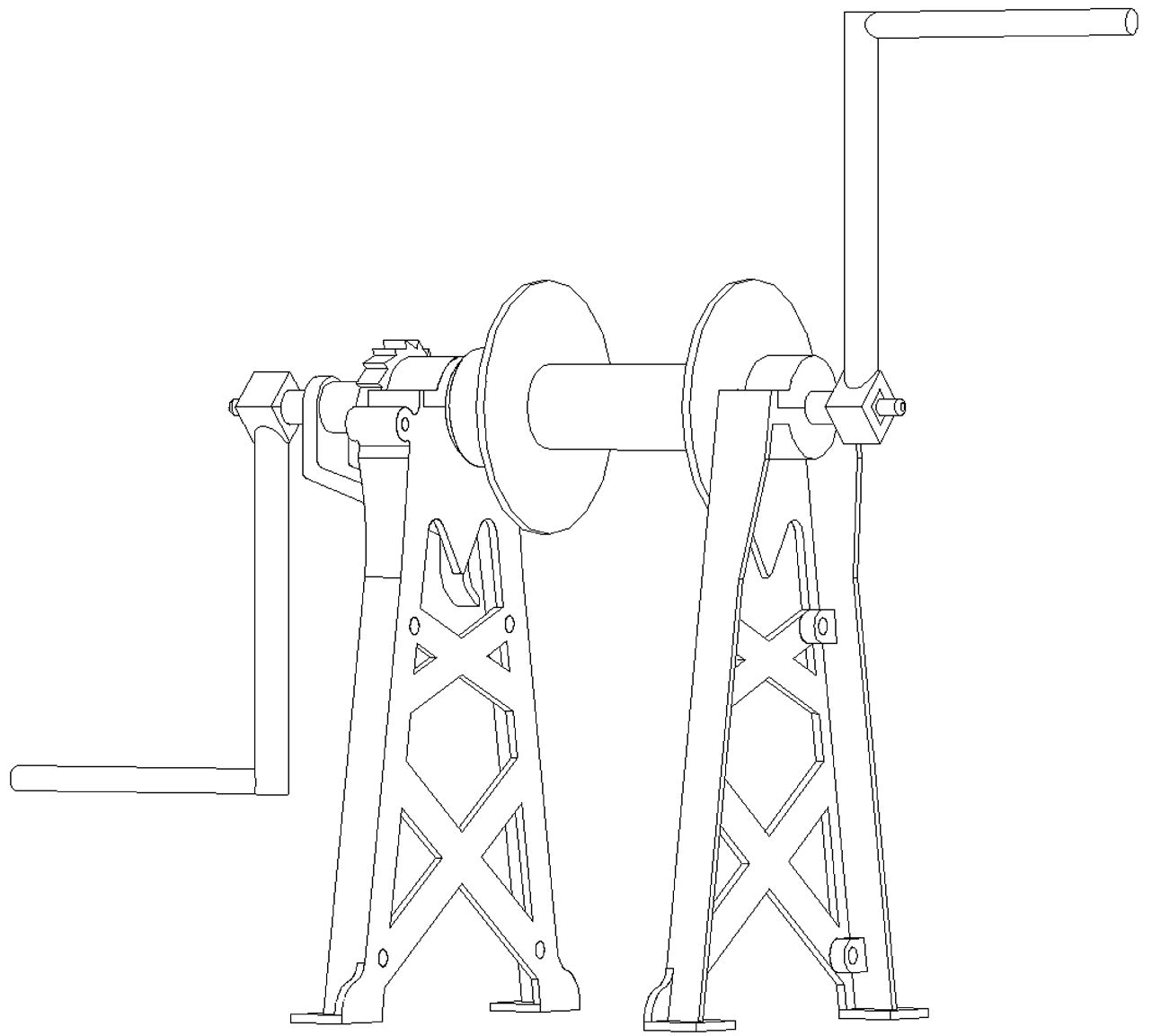
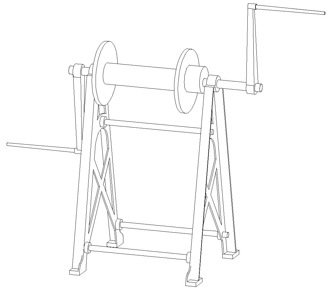
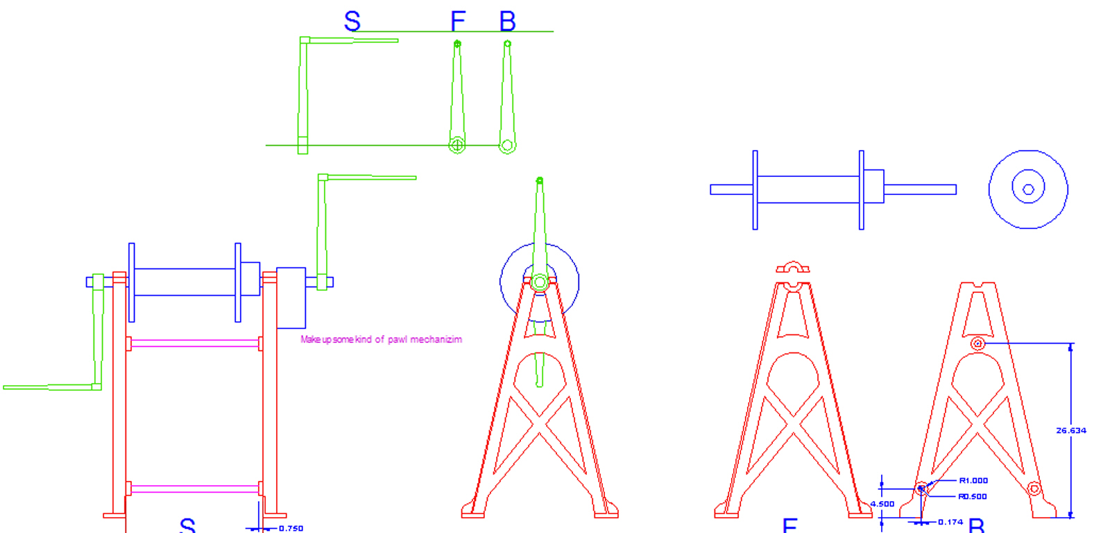
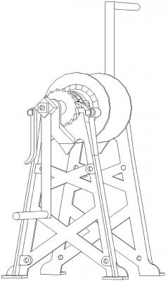
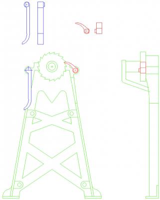
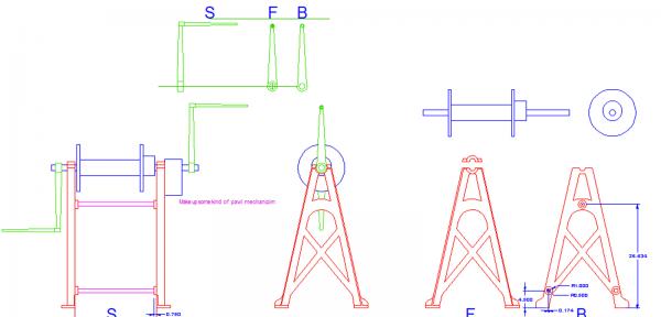
PART 23 I redrew the dredge winch during my Florida trip. One off the close up pictures I was sent. Here is the old drawing from the small photo I had. The 2D drawing of the winch and sub-assemblies. I shortened the handles, like I talked about in the earlier post. They are 23" long rather than 36". I think that is more reasonable for one man. The drawing of the Clutch engagement lever (left) and the Pawl (right). This is the front and back 3D views of the redrawn winch. Now that I am home again I'll be doing more work on the model. Finishing some details on the hull, and starting painting it.


-
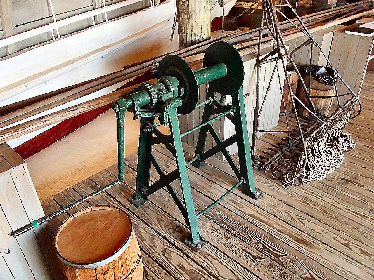
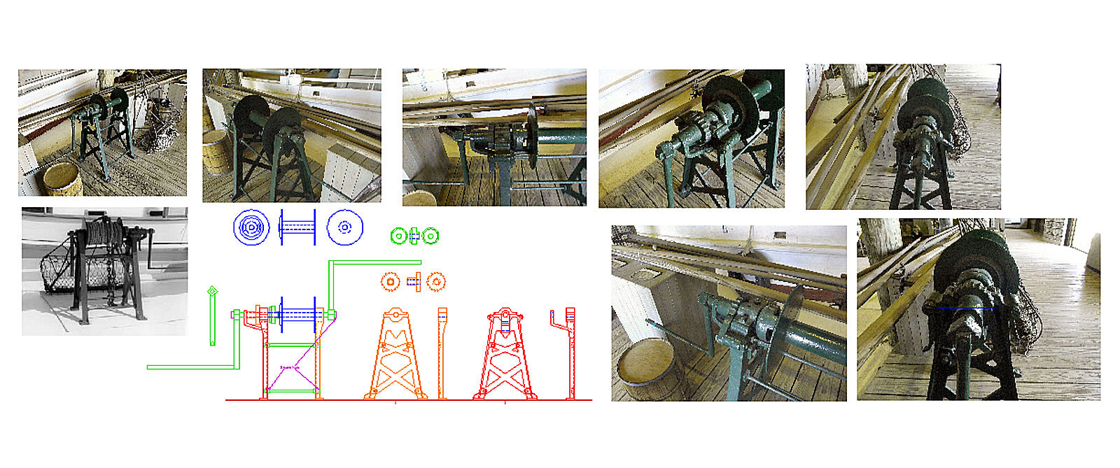
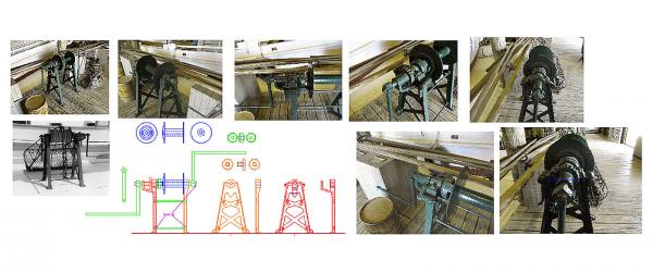
No building has gotten done, I'm away from home, but I have been able to do a better drawing of the dredge winches. Thanks to another member, I have some pictures of one in a Chesapeake Bay museum. This was the same one I based the old drawing on, but with a small photo to work from. Here is the old drawing. An overall of the new drawing, with the better photos. The drawing itself. The next task is doing a 3D drawing, then draw it in SketchUp, a 3D modeling CAD program. The crank handles are, I think, overly long. Compared to the old picture they are about half again as long. I think they extended the handles so that the museum could bolt them to the display (see the pictures).
-
I have not abandoned this build, just had many things get in the way. I have to go out of town, but will restart in Nov. I sold my Atlas lathe, and to clear a path to get it out of the back of the shop, I had to fill up the area in front of my workbench. It took 2 days about a week apart to get it out and loaded onto the buyer's truck. I bought his small 7X10 Harbor Freight (really 7X8 they exaggerate the size) metal lathe, so I will at least be able to make ship model parts. I need to do a bit of work on it, though, to bring it up to what I concider reasonable shape. It is almost new, but needs a lot of tweaking. I may also buy a second bed and extend it for making masts and spars. The extension would not be useful for metal work, but good enough for wood working.
-
Which Bluenose kit? (moved by moderator)
thibaultron replied to owend's topic in Wood ship model kits
I would personally avoid Constructo at all costs. Amati I don't know about. Artesania Latina has a reputation of not packing all the parts, or packing some from other kits, and horrible instructions. I had a Billings kit and was distressed with all the plastic parts it had. Model Shipways has a good reputation. -
Perhaps, The Sea Of Galillee Boat?
-
Darn. I like the Pyro kit. It and the Dutch Yacht were my favorites when I was a teen (that was just about the time the dinosaurs went extinct).
- 66 replies
-
- 3
-

-
- resolution
- hunter
- (and 2 more)
-
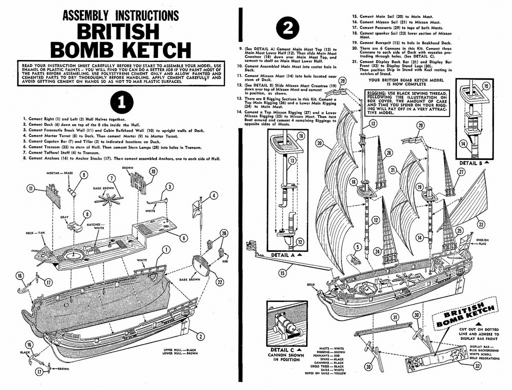
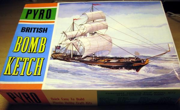
I have plans, but they are buried at the back of my shop, I'm doing renovations. Pyro made a model called the Bomb Ketch, and here are some pictures. The pyro model is what got me interested in the Marine Models kit.

- 66 replies
-
- 7
-
-
- resolution
- hunter
- (and 2 more)
-
Does anyone know if the old Marine Models kit for the bomb ketch is based on an actual ship? I think it was labeled as HMS Lion.
-
I have several kits, all from respected US companies, the dowels in all of them are mostly useless.
-
The painting of a 17th century ships hull
thibaultron replied to silverfoxes's topic in Nautical/Naval History
t the following site they have a converson chart for Floquil to other manfg. paints. This site says Vallejo Ivory matches the Floquil Antique White. https://www.microscale.com/Floquil%20Color%20Chart.pdf -
The painting of a 17th century ships hull
thibaultron replied to silverfoxes's topic in Nautical/Naval History
I looked up on the Web, and got the following information for the color values for Floquils Antique White: Name # Antique White Product # F110085 HTML # F1E8D6 CMYK # 5, 7, 15, 0 RGB # 241, 232, 214 This may be useful to someone. A paint store may be able to get you a swatch to use as a comparison for mixing your own. -
What did you have to trim?
-
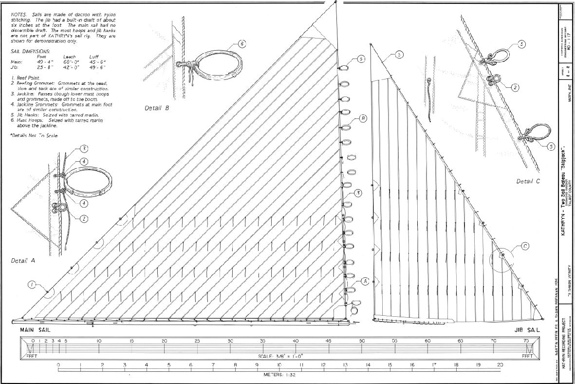
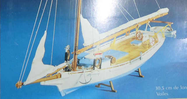
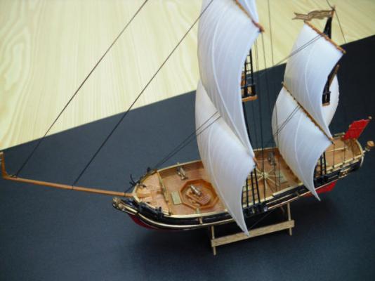
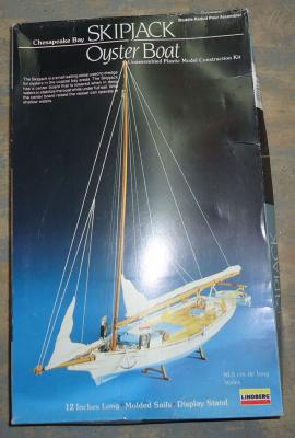
The post #14 in the thread "Furling a boom-footed forestaysail" on this forum has interesting information on how a main sail would be attached to the mast hoops, on a boat with a steeply raked mast, which the skipjacks have. The above thread has much more information on this. They have a large rake on their masts, and the foot is basically immovably attached to the boom. The sail would jam, if directly the leading edge was laced to the hoops. So they have a rope running between the lower hoops and the sail hanks. This rope was loosened when the sail is lowered, allowing the leading edge to slide back. This is a drawing of the sails of the skipjack Kathryn. Notice details A and B. And here is a picture from the top of the box of Pyro's skipjack model showing the sail being lowered. When I started on my model, I thought that they had not cast the sail correctly. I'm used to modern sailboats.

-
Part 22 I guess I owe Pyro an apology. At the beginning of this build, I commented that the casting they made for the furled, or as it turns out being furled, main sail was incorrect. I think I used a stronger comment. Because I'm used to modern sailboats, I said that they had cast the angle of the leading edge, in the wrong direction, as it angled away from the mast. They had it right! After reading the thread "Furling a boom-footed forestaysail" on this forum, post #14 described how the sail is attached to the hoops. The foot of the mainsail is laced to the boom in such a fashion that it cannot side forward as the sail is lowered. With the steep rake of the mast, the leading edge would jam as the sail was lowered. I have not worked up the geometry for this, I'll take their word for it. To solve this problem, the lower part of the sail is not directly laced to the mast hoops. Instead there is a rope that runs between the sail hanks and the hoops. I'm not explaining this well but the drawing that will follow should clear it up. As the sail is lowered this rope is loosened and the leading edge can pull away from the hoops, letting it slide back. Detail A shows how the lower part of the sail is attached to the hoops by a rope running between them and the hoops. Detail B shows the upper hoops laced directly to the sail. So Pyro’s casting with the lower part of the sail pulled away from the mast, as it is being lowered, is correct. The jib has only a partial boom, so this is not a problem. It is hanked directly to the stay. Learn something new every day.


-
AUTOCAD 18 DELUXE
thibaultron replied to yamsterman's topic in CAD and 3D Modelling/Drafting Plans with Software
I can't help you with AutoCAD, but I did do a step by step for CADing a simple boat for the builder in the below build: America Schooner POF by Walter BilesThe procces used may help you.