thibaultron
-
Posts
2,952 -
Joined
-
Last visited
Content Type
Profiles
Forums
Gallery
Events
Everything posted by thibaultron
-

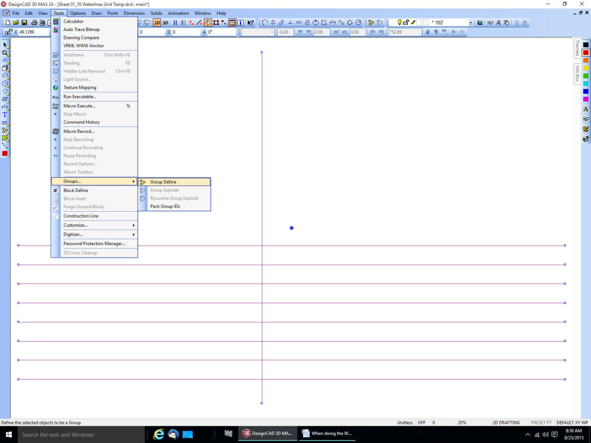
TurboCad Printing - NEED HELP
thibaultron replied to Mahuna's topic in CAD and 3D Modelling/Drafting Plans with Software
Your welcome. -
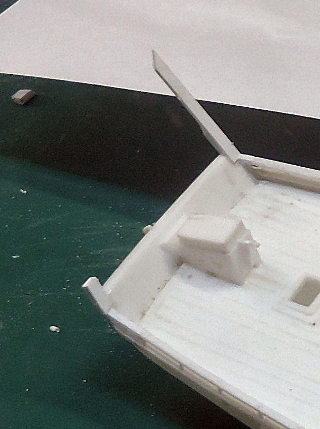
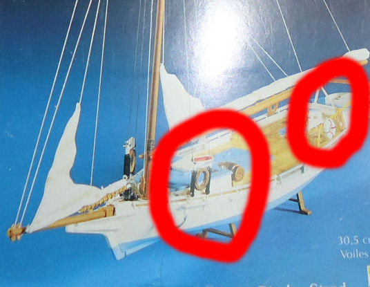
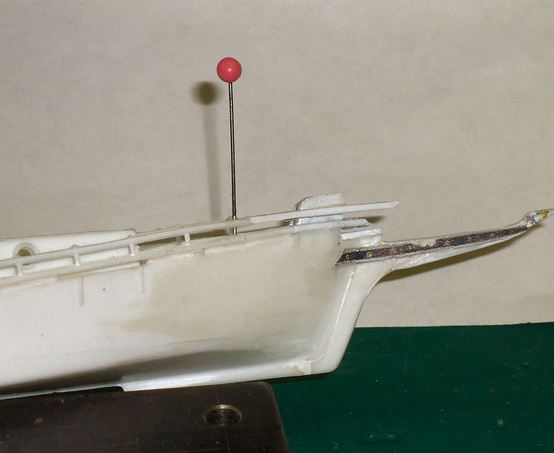
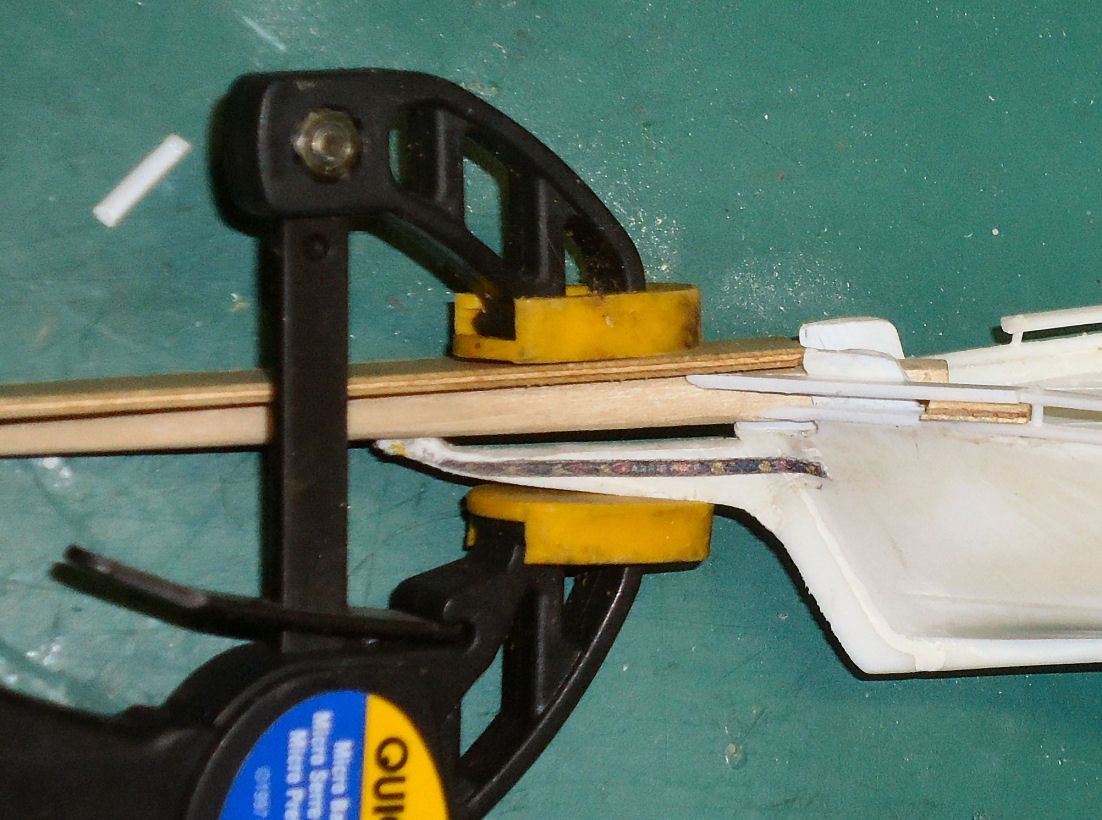
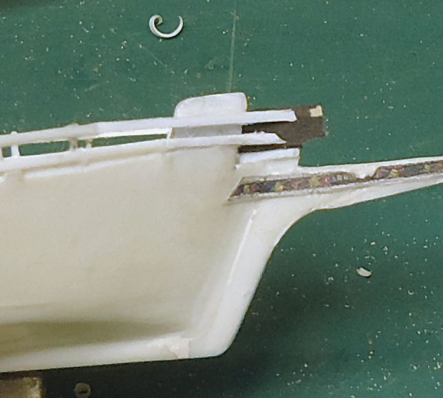
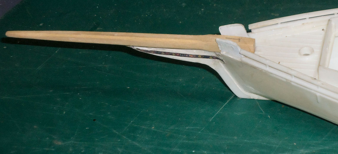
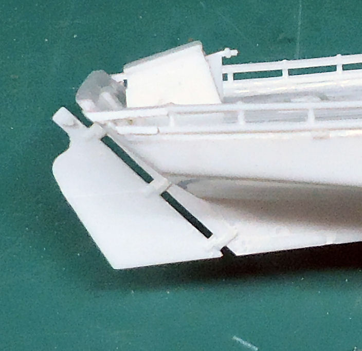
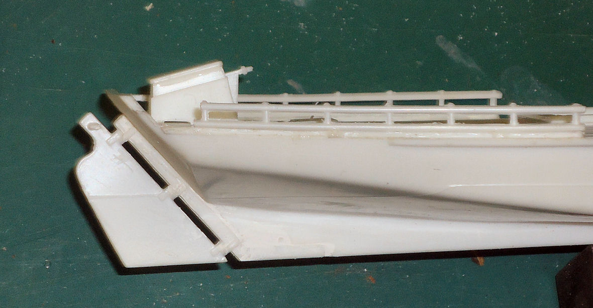
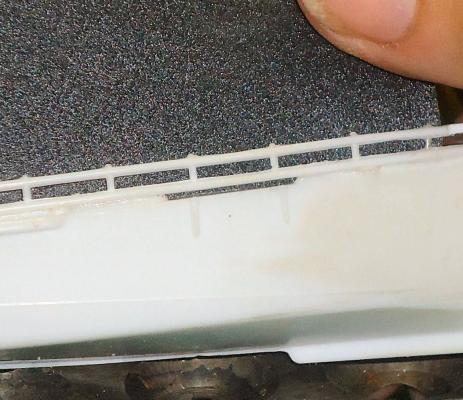
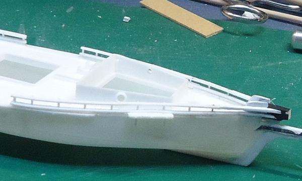
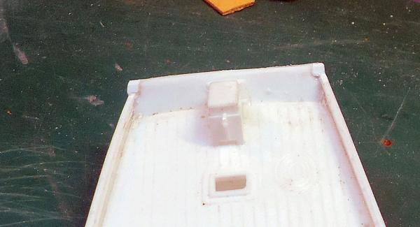
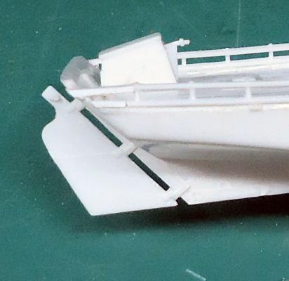
Part 16 The transom on the model is notched where the rails end. On the plans the transom goes up “straight" and the rail ends butt to it. It took leftover pieces from the railing stock and glued then in the notches, after cleaning them up a little bit. The pieces were larger than the notch on all sides. After letting the glue dry for several hours, I filed the plastic to be flat with the front and back of transom, and with the edges of the transom in line with the hull. A couple notes on this: I used the “Fingernail Test” to determine when the new parts were flush with the old. This involves running your finger nail along the seam. If it slides past the seam without catching, the seam is flush. Machinists used this test on their parts. Look at your files, some of the flat ones will have a “Safe Edge”. There is one thin side with no teeth. This allows you to have this edge against a surface that you do not want to remove. I had the safe edge against the top of the railings. Not all files have this, so check yours. The next order of business, was the chain plates. The kit had a couple problems with these. The chain plates, deadeyes, and shroud lashings were all cast as one piece. To use them as is safely I would have had to attach them after I painted the hull, and was installing the spars and rigging. I would rather paint the chain plates with the hull. Hole in hull where chainplates attach. The kit parts also had a bar between the chains at the bottom, and a coil of rope suspended between the shroud lashings (see the left hand red circle on the box art, below). If you look at the second red circle, you can see there was a similar rope coil on the railings, I removed this too. The rod was not shown on my plans for either this boat, nor the Willie Bennett. A circular coil of rope is not something you would find on a real boat, that is not how real rope hangs. A couple months ago I carefully used a razor saw and knife to remove the coil. I decided to cut the chain plates free and, if I decide (likely) to use the rest later, I will remove the lower bar, and thin the upper. While the shroud lashings are crude, I don’t think I could do any better with real scale deadeyes and thread. The running light boards are also attached the these parts, making keeping them more attractive. I may scrape groves in the cast lashings with a knife to make them look more like separate lines. After I cut the chain plates free I removed most of the casting lines. I left a little to represent the line between the part attached to the hull, and the cap bolted to it to lock in the deadeye straps. I drilled shallow holes in the tops of the chain plates where the cast straps had attached, to mark their locations, only to find that stock positions of these joints did not match the locations of the straps cast on the hull. I’ll fill them later. I glued the chain plates onto the hull. I've been researching the Skipjack Push Boats a little more, and will be talking about them next time.


-
TurboCad Printing - NEED HELP
thibaultron replied to Mahuna's topic in CAD and 3D Modelling/Drafting Plans with Software
I don't have TurboCAD, but have a couple others. Look at the options when you bring up the Print window. Is there an option to change the scale ratio of the printout?. DesignCAD has a couple of them. Maybe the default margins, or the paper size options are wrong. I hope this helps. -
18th Century Shipwreck Found In Maryland, USA
thibaultron replied to thibaultron's topic in Nautical/Naval History
http://www.usatoday.com/story/news/nation/2015/08/26/200-year-old-ship-found-under-md-bridge/32380069/ -
http://archaeology.org/news/3634-150825-maryland-ship-timbers
-
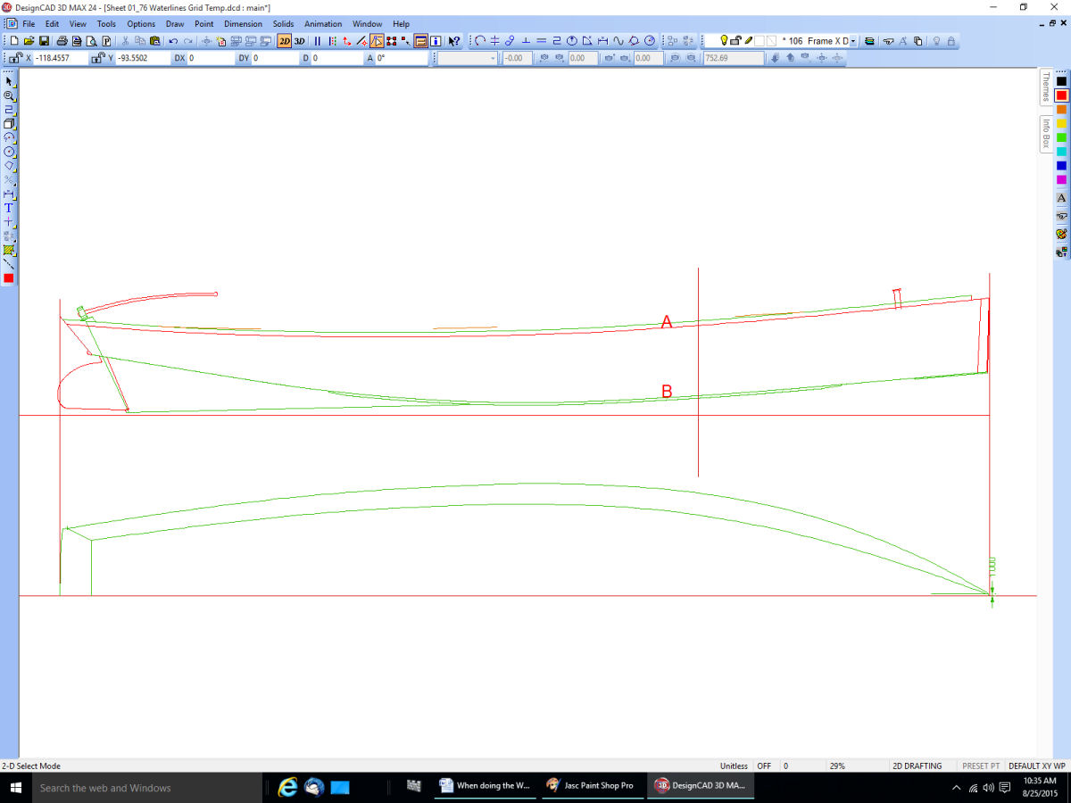
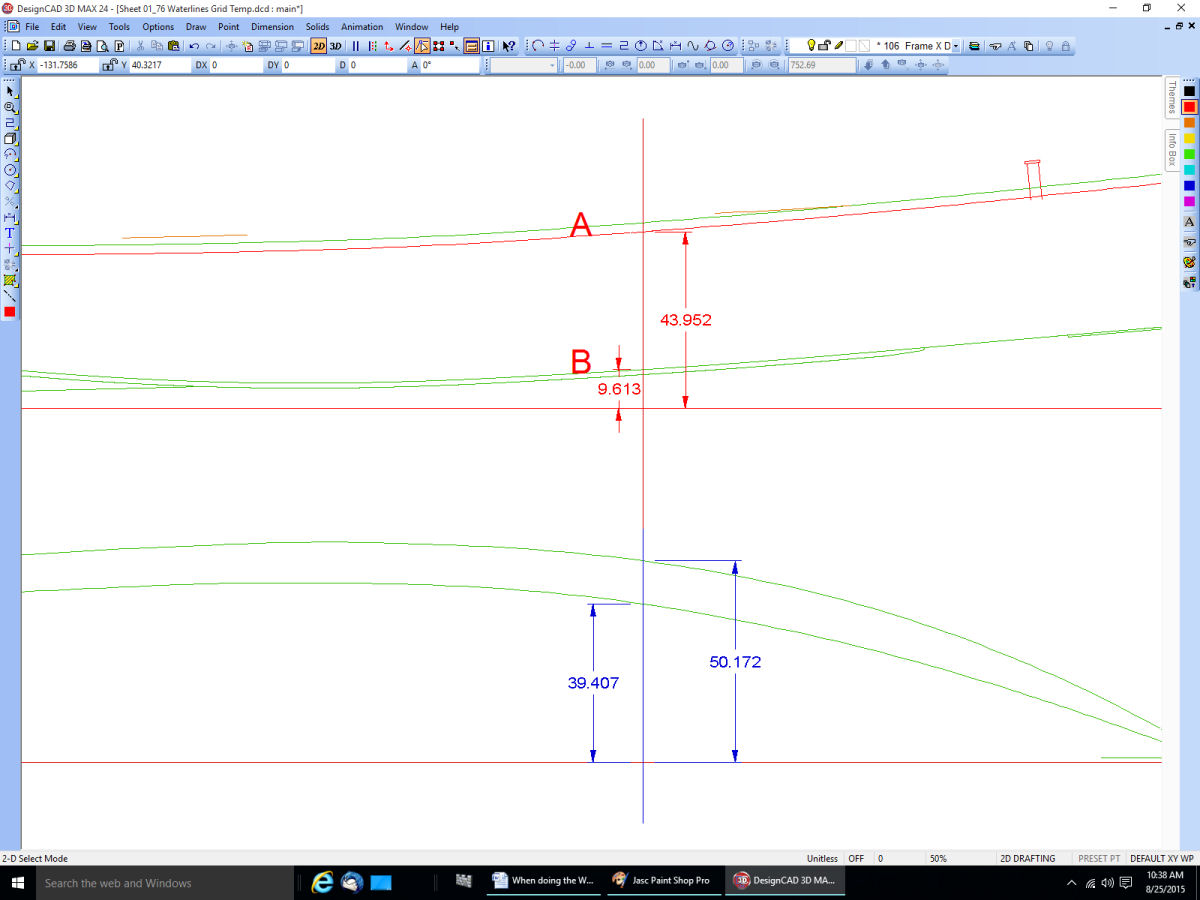
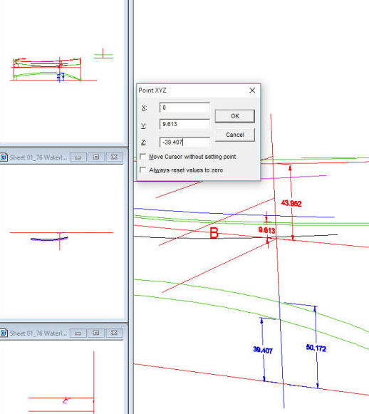
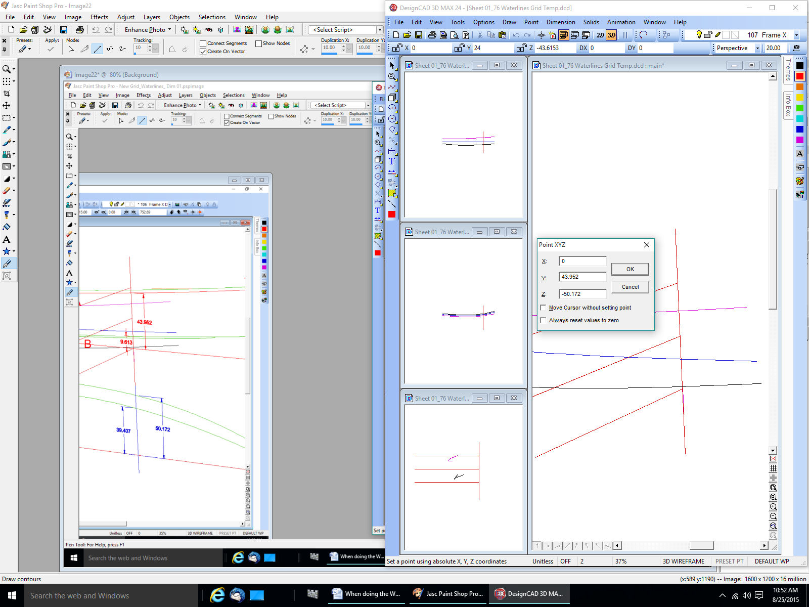
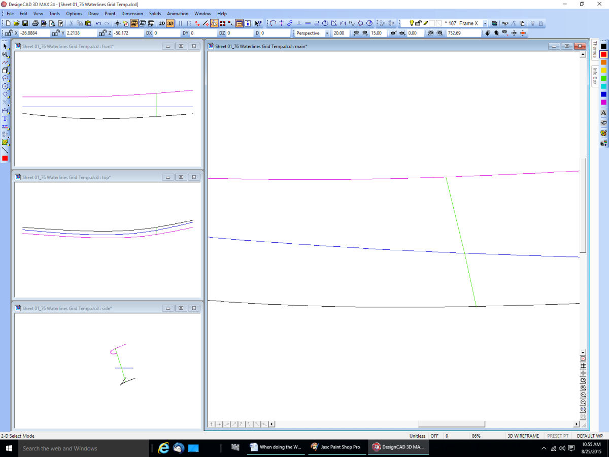
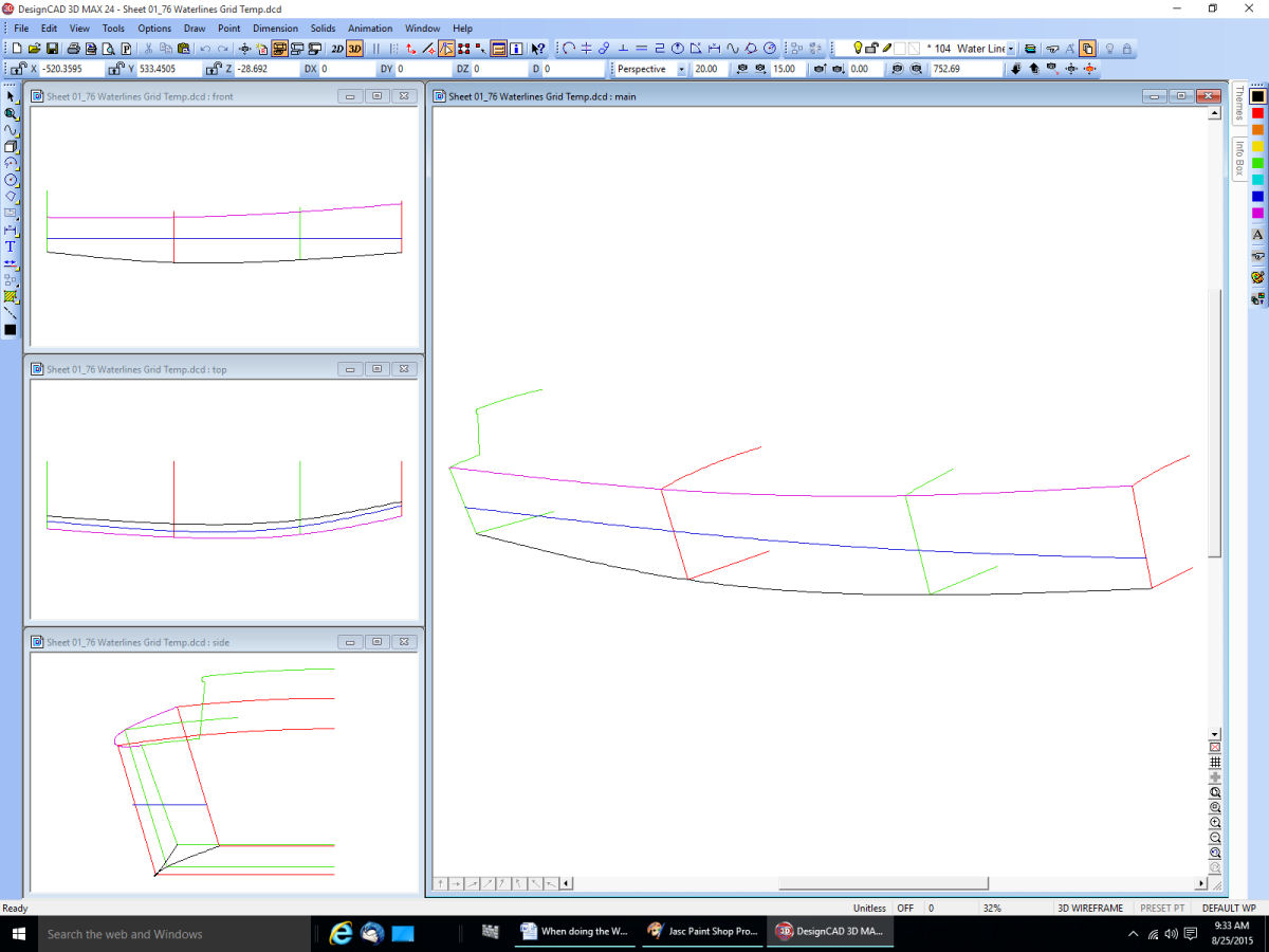
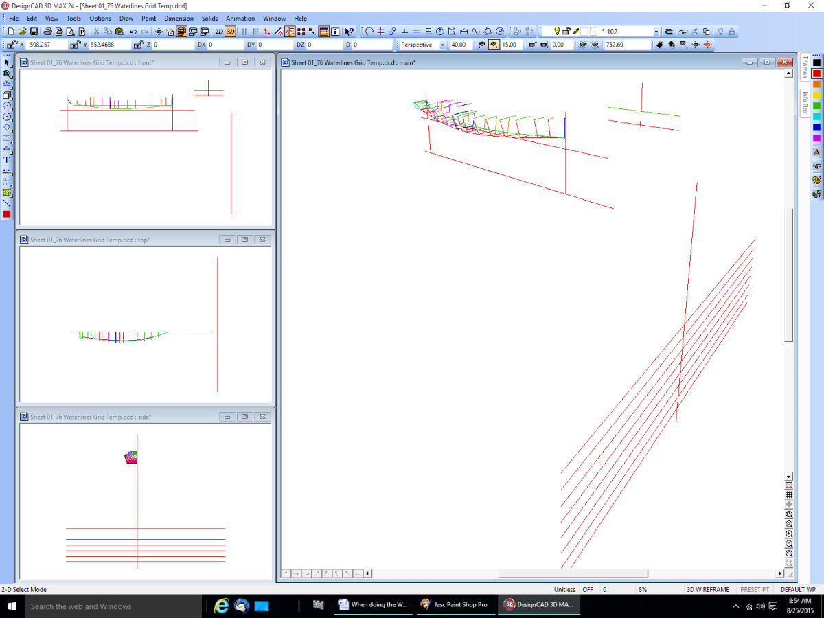
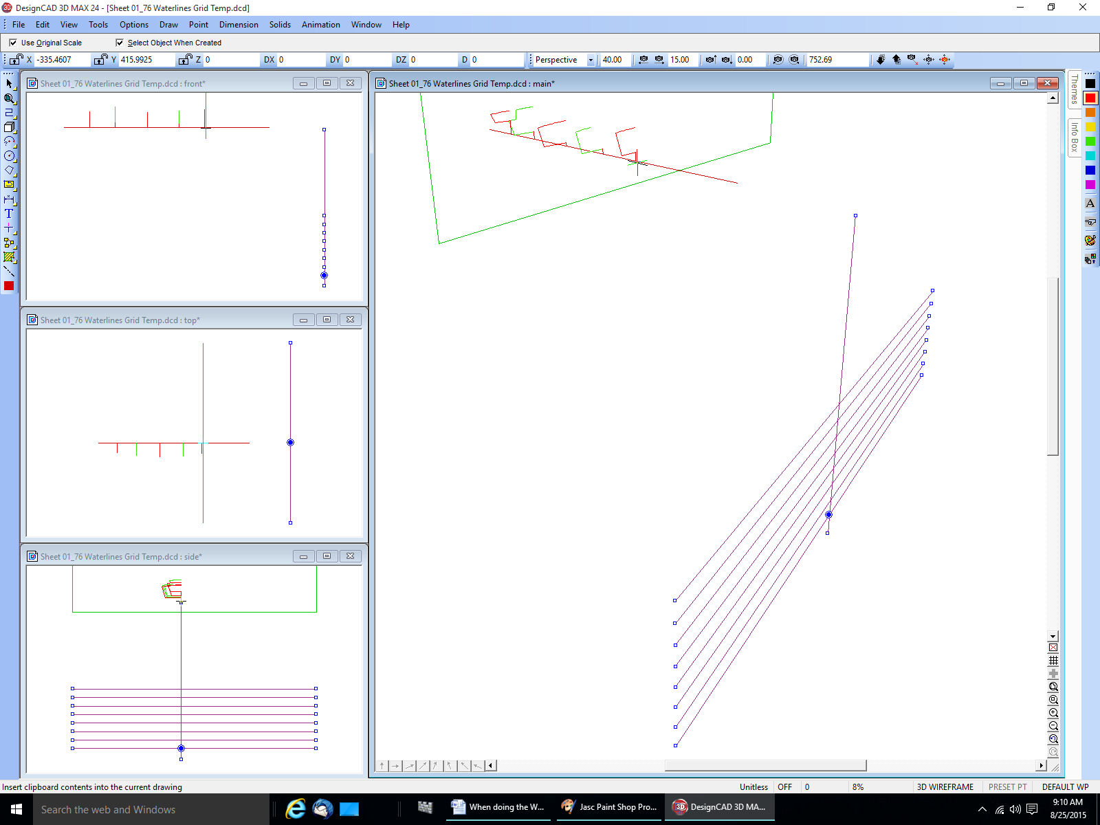
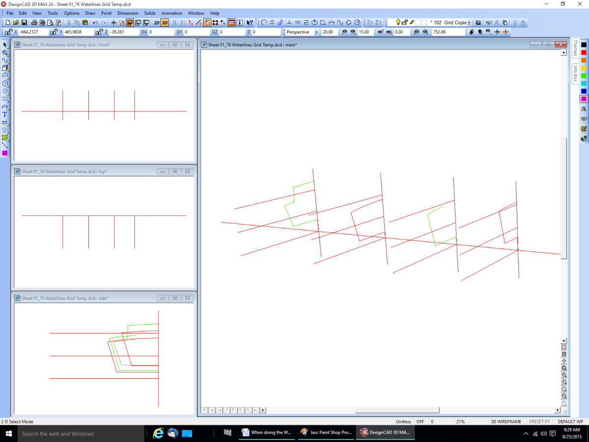
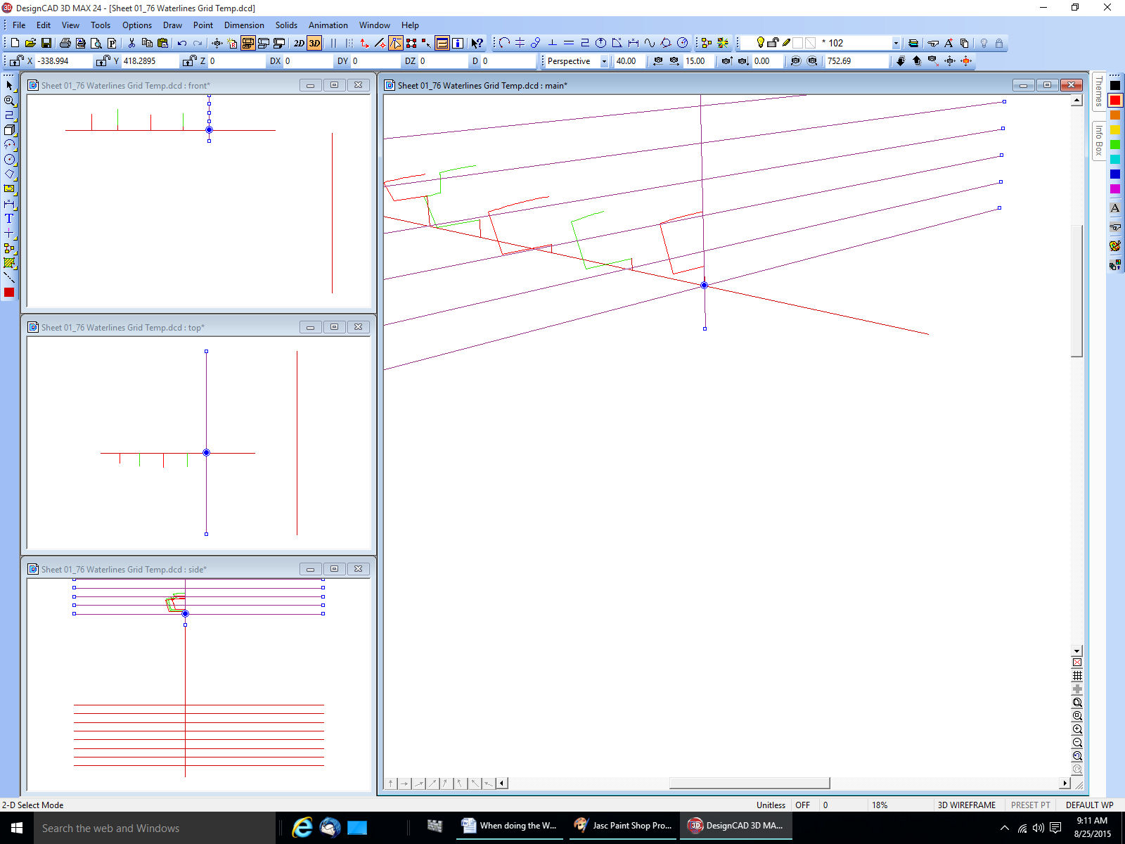
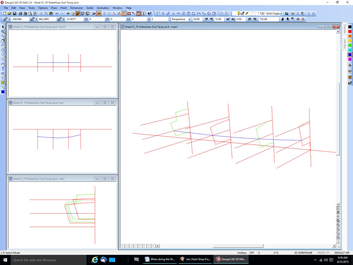
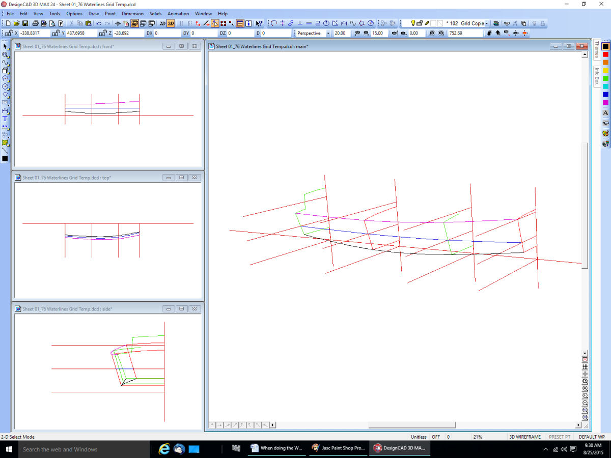
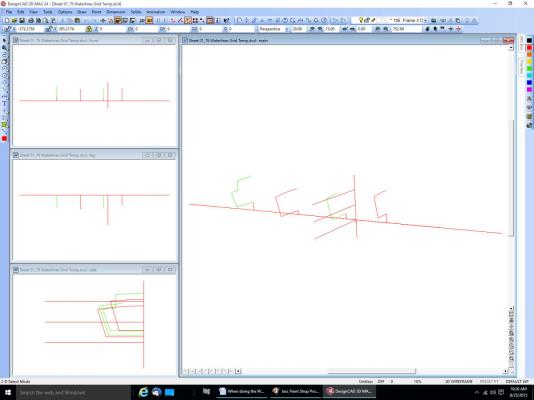
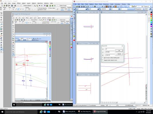
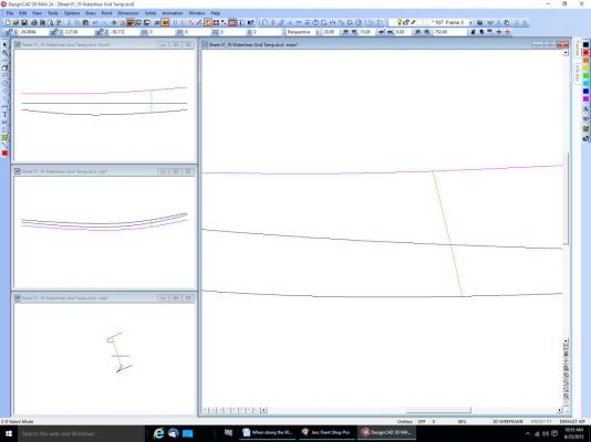
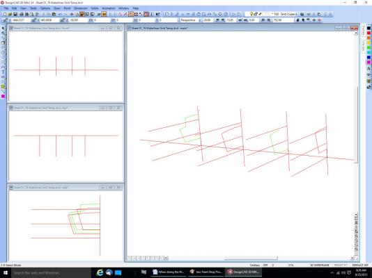
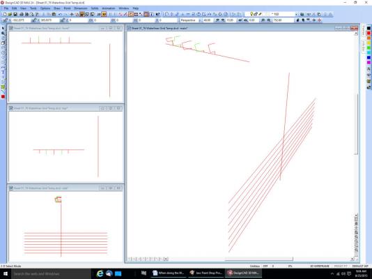
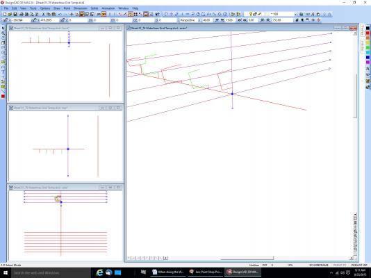
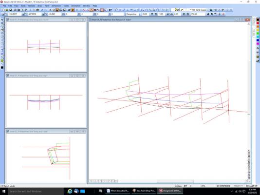
Part 2 Without the all the other lines here are the shear, chine, and new waterline. Now copy a grid to the new frame location. To generate the new frame you draw a curve to the intersections of the new frame grid and the waterlines. Here in lies the rub. Notice that the shear and chine lines do not fall on a grid line. I have never been able to figure out how to draw the curve to these points, as there is no intersection with the grid. I’ve tried locking the Z axis, drawing a perpendicular to the reference lines, etc. The program always chooses the point on the line closest to the cursor. You cannot place the cursor at the right spot, that is what you are trying to find for the new frame. The only way I have found to do this is to go back to the 2D side and deck views I drew previously along with the frames. I always draw these first from the drawing or Offset Table. Then I turn on the layer with the new frame grid, and draw a line top to bottom on the 2D layer. Then I dimension the intersection points I need. For a drawing with curved frames, you would still need to find the shear and point where the planking meets the keel. This is a pain! If someone knows how to do this, please tell us. With these points found I go back to the 3D view. I use the Point XYZ command “:” And enter the first point. Then I select the intersections of the grid and waterlines. In this case only one. Then use the point command again for the other end of the line. This completes the first new frame (green line). I hope this helps. It would have been better with curved frames, but I don’t have any drawings with those, yet. I’m doing one for the next boat. Fortunately it has a straight keel to planking line, and the keel is not tapered along its length. Another way to do it is before you go to 3D and place the frames, draw a grid on each frame layer. This does clutter up the frame drawings for other purposes though. It can also make setting the frames in 3D difficult, with all those lines.
-
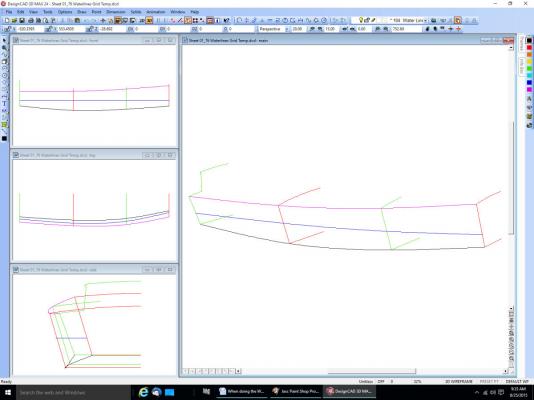
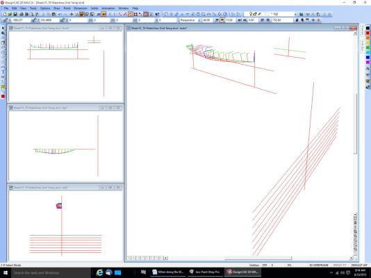
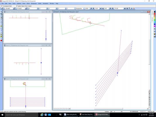
Part 1 When doing the Waterlines, use a different layer for them, like you did for the individual frames. Not everything has to be on layer 0. I use many layers in my drawings, sometimes for subassemblies, like a frame, or even individual parts (tiller, mast, centerboard and housing, etc.). On my Terrapin Smack I have two layers for the centerboard, one in the up position, one in the down. At the present time I have somewhere around 40 layers. I sometimes have several layers for a “thing” as I progress in drawing it, just in case I make a mistake, I can go back to the previous layer, much as using the Save As command. Sometimes I do this if I am not sure of the part/section I’m drawing. I may not completely understand a part of the drawing, or it might not be clear which line of a detail area is part of the detail, or just a line overlapping from another. For example I have multiple layers for the trailboard graphic on my skipjack drawing. One for the outline, another for the eagle head craving, etc. I turn on as many layers as I need as I go. When I was done with the initial design, I later made new layers with changes I felt would make it look better. This way I could easily select from any of the layers to compare old and new. If I decided for example that a line in the carving design needed to be different, I could change it, then switch between the layers, or turn them both on at the same time to compare old and new. Much easier than looking at different versions of different drawings. As of my latest Smack drawing I am at version 76. Sometimes I have to go back a version or two and restart from there because I made an error that is easier to correct by redrawing from that version, than trying to correct the one I am on. Typically I deleted something I should not have, or really messed up a section I have been working on. If I’m on version 50 for example I might go back to 49, correct the error, then save this as version 50, overwriting the mistake. I might also go back to an earlier version, and just copy something from it to the latest version, if I deleted something I should not have, perhaps I even deleted it a couple versions back, and do not want to lose the additional details I have drawn since then. I generally save a new version after any major change, or several times a day, if I’m still on the same part. As in making the model itself, sometimes you break a part off ,and have to replace it, or decide you can make it better than the first time. Now onto your question. Now that you have your frames, you can go a couple routes. The easiest one will involve some more drawing, but be clearer on your final drawing. One thing to remember is that you can move the origin (0,0,0) to anywhere on the drawing with the Point – Origin command. Create a new layer, call it for example “Water Line Grids”. Switch to 2D mode. Draw Your waterline grid, using whatever spacing you want. Then select all the lines and make them a Group. Select where the baselines cross. Go back to 3D, then rotate the grid 90 deg. Around the Y axis. It will look something like this. Here’s a view with some of the frames removed for simplification. Now select the intersection of the grid and baseline again. Copy the grid “Ctrl C” and then paste it “Ctrl V”. You will see an outline of the group that will move with the cursor. Go to the intersection of the first frame and the baseline and select it “F4”. The copy will drop to this intersection point, and you have your first waterline grid placed. One important note about the F4/intersection point command. If you have 2 or more lines laying on top of each other, the program can not figure out which of the overlapping lines you mean, and will fail. For instance in this drawing, if I copied the baseline from another layer, or redrew it for some reason, and had both layers on, the command would not work. I would either have to turn off the original layer the line came from, or erase the line on one of the layers. This one gets me all the time, expecialy in 3D where lines can be on top of each other in one of the views. From here on I simplified the grid and removed some of the frames, to make it easier to see what is going on. I copied the other grids in. Using the Draw – Lines – Curve Connect the intersections of a waterline and the grids. The blue line below. Next I connected the shear and chine points.
-
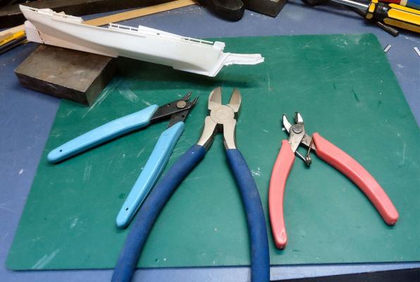
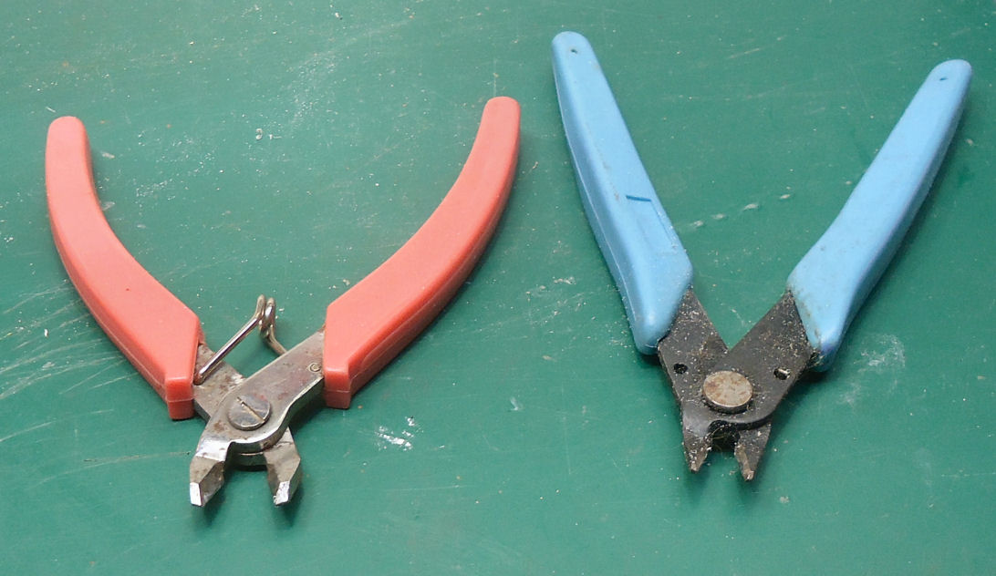
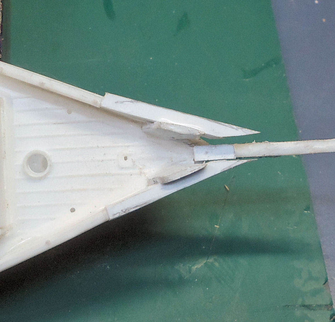
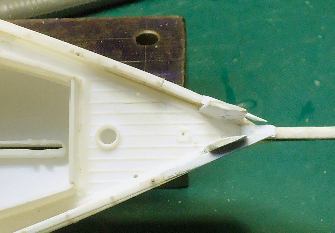
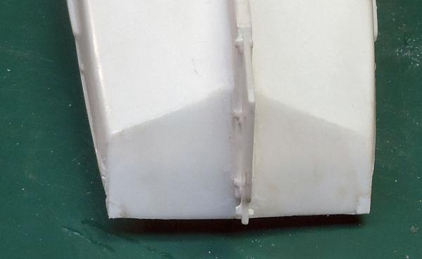
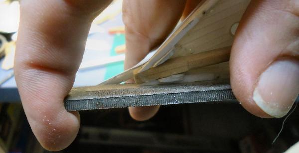
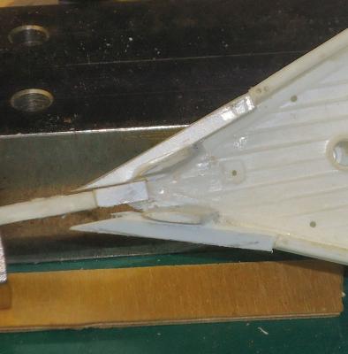
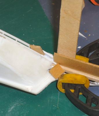
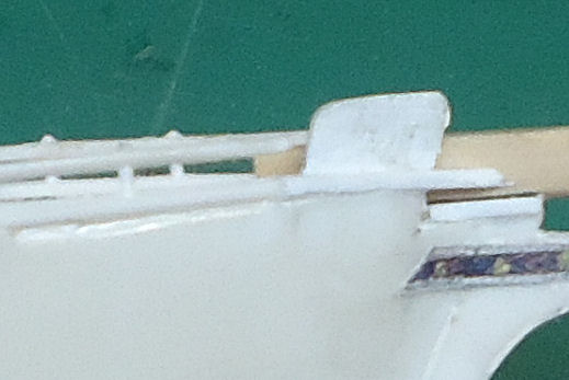
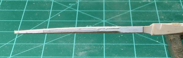
Part 15 I started on the fore upper rails next. I clamped a block at the top of the bowsprit, where the railings would meet it. This is a little high per the plans, but the kit railings are high. In fact the new sections dip a little between the old rail and the bowsprit. Maybe no one will notice. I also placed a block between the lower rail and the new piece. I glued on the port extension first. The starboard rail extension followed. Then I trimmed the starboard rail, and found a problem. It’s hard to see in the photograph, but when the new section was sanded to match the old, there was a kink right at the joint. The old railing tilted inward about a ¼ of its width. It was much more visible when looking at the ship from above the bow. As this was right in the area that you would first see when viewing the model, I decided to correct both rails before continuing. I would need to cut some stanchions and move the old section outward. This involved what I have been trying to avoid, drilling a small hole in a small part. I removed the first stanchion and cut loose the bottoms of the next two, and cut off the bump at the top of the rail that represents the top of the stanchion rod, where the head of the rod/bolt is. I also broke the joint between the old and new sections. I used a piece of wood clamped to the deck to push the old rail end outward, and stuck a 1/16” piece of plywood between the upper and lower rails to support the upper rail during drilling. Then I drilled through the upper rail in the former location of the bump, with a #76 drill (about .020” in diameter, the railing was .060” wide). Once I had the hole through the upper rail, I removed the ply block and drilled the lower rail, also in the center, sort of. When I was done I found that the drill bit had wondered and cut down the outside of the lower rail, rather than the center. So I drilled a second hole a little further back. The second hole was a little off at the top rail, but spot on for the bottom. I decided that it was good enough. I used a #73 drill to open the holes for the pin used for the new stanchion. You can see the two holes at the upper right of the picture. For this operation I used my Optivisor (with its greater magnification), and went slowly. I inserted a pin into the upper and lower holes as the new stanchion, and secured it with thin super glue. I also used the super glue for the railing joint. I cut the pin off with rail nippers. They are like heavy duty sprue nippers. They are used for cutting the track rail on model railroads. I then filed the protruding portion, leaving a little at the top to represent the bolt head I had trimmed off before. On the left are the rail nippers, on the right the regular sprue nippers. You can see that I managed to knock off the port rail extension during this process. A pain, but I would have had to break the joint between the new and old rails anyway. A little further sanding and the rail was finished. I used thin plastic cement to reattach the bottoms of the other two stanchions I had cut earlier, they were shifted a little but still looked centered. I repeated the process for the other rail. While trimming the rail I held the bowsprit, reversed, in place to reinforce the railing, and hold it in place at the tip. This is not how I held it and the file during the trimming, but I had to use my other hand to snap the picture I used the large file to remove the bulk of the material, then switched to a needle file to finish. After trimming the rail, I glued the stub of the incorrect bowsprit in to protect the rails while I do more work on the hull.


-
3D printer at Home Depot
thibaultron replied to twintrow's topic in CAD and 3D Modelling/Drafting Plans with Software
The Home Depot people will likely have no clue, unless there is a demo setup to show you the pretty frog or whatever that it can make. Years ago (yes lots) when the Commodores and Radio Shack computers came out I went to RS to look at their computer. The salesmen there had NO idea what their computer did, They could not even answer questions as basic as how much memory, or the number of pixels in the resolution. Nothing even close to the info in a Commodore add. Ended up with a Commodore 64, and over time most of the needed accessories. Made some money off it back then, I wrote a few articles on programs for it. -
3D printer at Home Depot
thibaultron replied to twintrow's topic in CAD and 3D Modelling/Drafting Plans with Software
I mentioned this in another modeling forum, and they said run don't walk away. Very poor resolution for the price. -
Mahuna; Thank you!
-
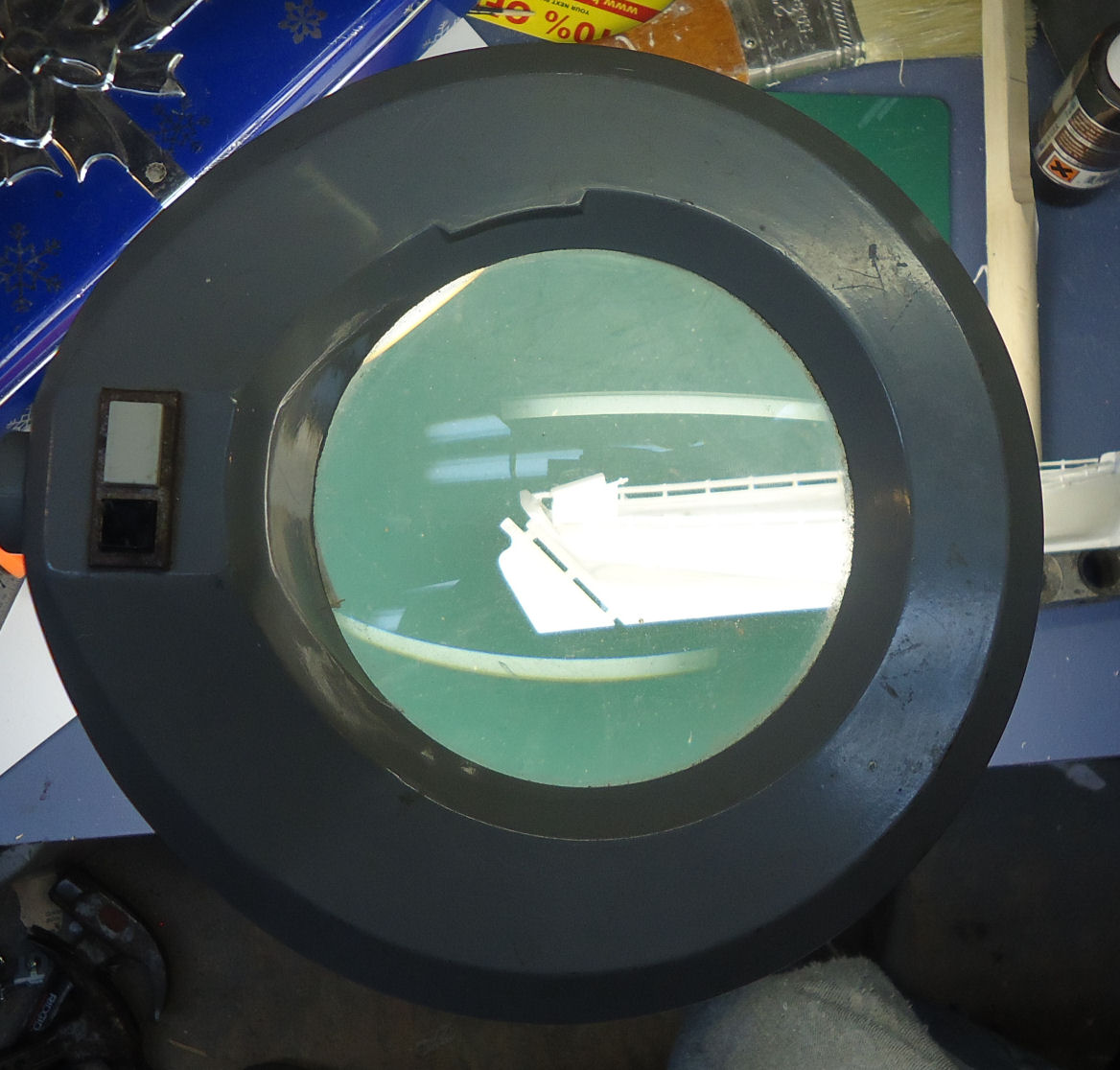
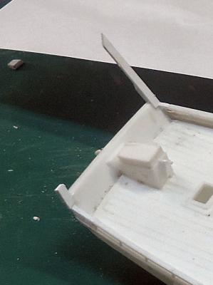
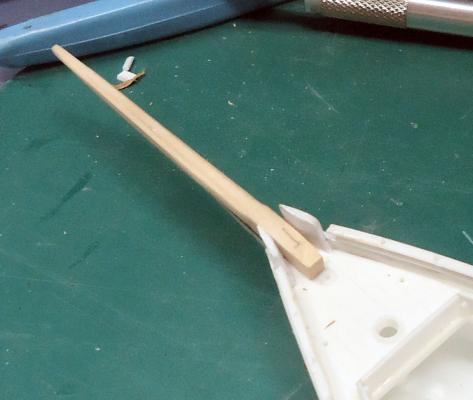
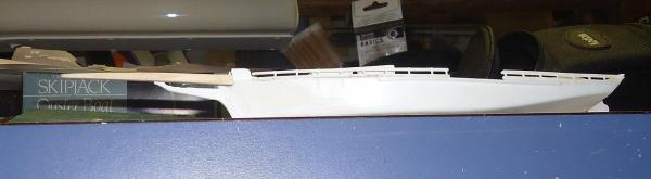
Part 14 I worked on the rails, to extend them front and back. I did the port side upper railing first. Mistake! After I got it on I realized that the gap on the lower rail was too small to work on with the upper rail in place. Also I just trimmed the end of the rail flat and tried to glue the small piece I needed to fill the gap. The long overhang of the model rail from the last stanchion allowed the joint to flex all over the place, making gluing difficult. I finally managed it, but was smarter with both rails on the other side. Notice the short lighter white section of new rail at the top. On the bottom you can hardly see the new piece. On the second side I trimmed both the lower and upper rails back close to the stanchion. I smartly did the lower rail first this time. Unfortunately I forgot to take pictures of these steps. It cut a piece off of .040” plastic sheet to about 7 or 8/32” wide and 5” long. This should have been enough, but I ended up making enough scrap that I had to cut another piece. These parts are very small, and it took a few tries on some. I fit the pieces so that they were even with the inner edge, and the excess width was on the outside. I then sanded the outside to match the existing railing. Lower installed and trimmed, then the upper. With the upper rail trimmed close to the support, this was easier. You can see here that the new section meets the old close to the stanchion. After looking at the plans, I will have to fill in the sides of the transom, it should go all the way to the outer edge of the railings. Next I turned to the railings in the bow. First I temporarily glued the bowsprit in place with white glue. I decided that trying to trim them to fit the spar after I’d installed them would be harder than fitting them with it in. Once again I did the lower rails first. The lower rails installed, before trimming are shown above. The lower one is not off center it just looks that way in the photo. I removed the bowsprit for the shaping. Notice that I also had to add a piece of plastic to the top of the stem. The model piece did not quite go all the way to deck level. Here they are after trimming. After trimming they look better. At this point I’ve reinstalled the bowsprit for the fabrication of the upper rails. When I do the upper rails I’ll again trim them back to the stanchion. I let the glue dry overnight. For those of you who wonder how I see all these small parts, here is my “eyes”. Using this is somewhat of a pain, as I’m constantly hitting it with the tool handles, but my Optivisors have too close a focus distance for me to comfortably use them for work directly on the model with it on the bench. My hands are not steady enough to hold the model in the air, most times. I spent all morning going through the dowels I bought, and a number of my kits looking for the 1/8” and 3/32” stock I needed for the boom and mast. None of the recently purchased dowels (5 in each of the two sizes) were straight for their full length, not even for the 12” I needed. I picked out two of the 1/8” that were warped the least for the boom. Then I went through my kits looking for a 3/32” dowel. After about five or six kits with 3/32” dowels I finally found one that was straight. I need to find a new source. The kits I can understand, they are almost all three or four decades old. Still disappointing.


-
I prefer building ships and other models that are based on real ones, except for Sci Fi ones. So I try to do some research on them. Some like the schooner Flying Fish which is a future project, I can find no information on, so I mostly follow the plans.
-
Shades (sorry) of the movie "Operation Petticoat". A comedy movie about a WWII US sub that ended up being painted pink.
-
Thank you for pointing out this movie. I much enjoyed it, and learned about a great military man I had never heard of. I looked him up on Wiki, and he was truly a great leader.
- 1 reply
-
- 3
-

-
- film review
- The Admiral: Roaring Currents
- (and 2 more)
-
Your welcome. I've loved them for years.
-
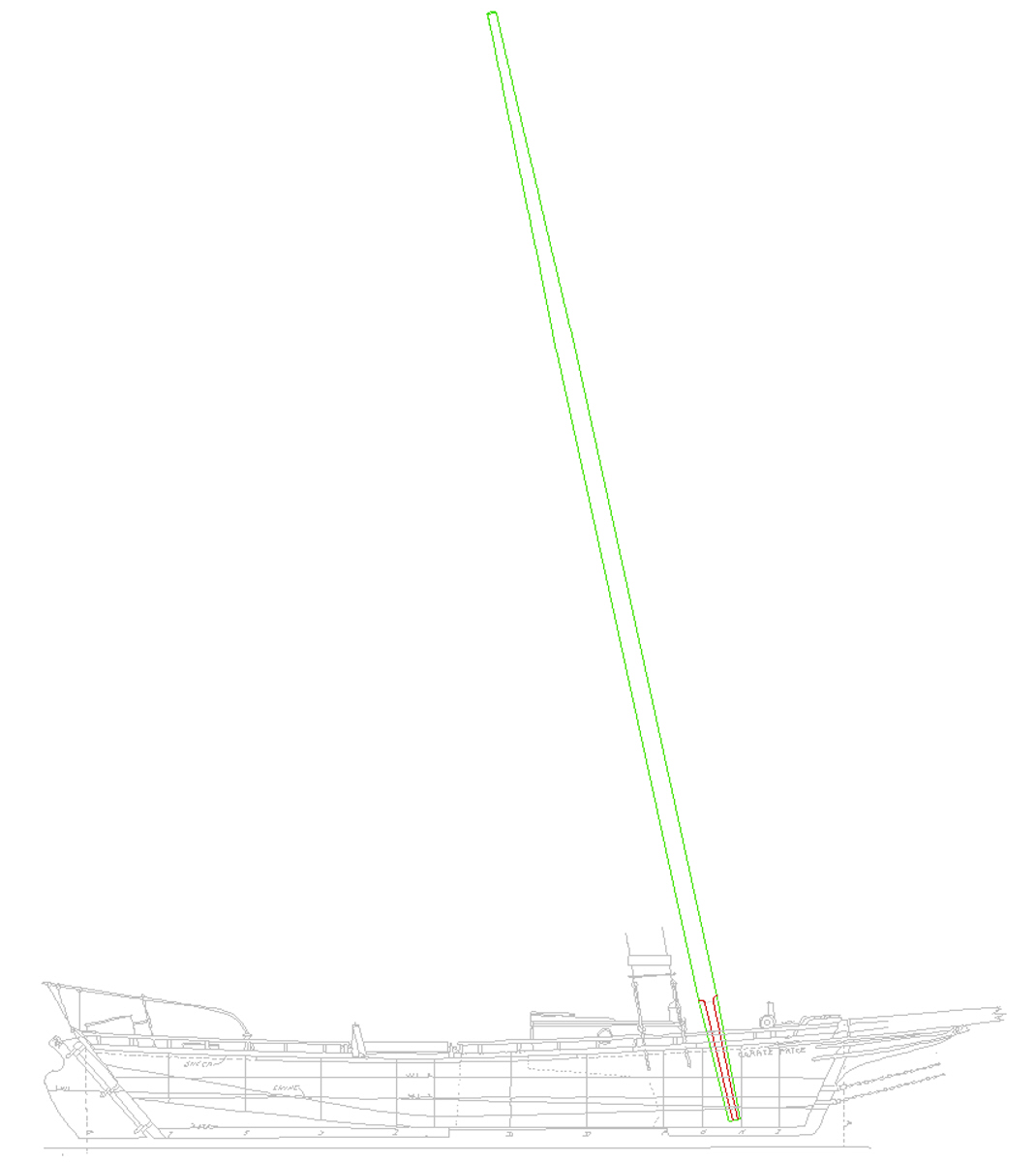
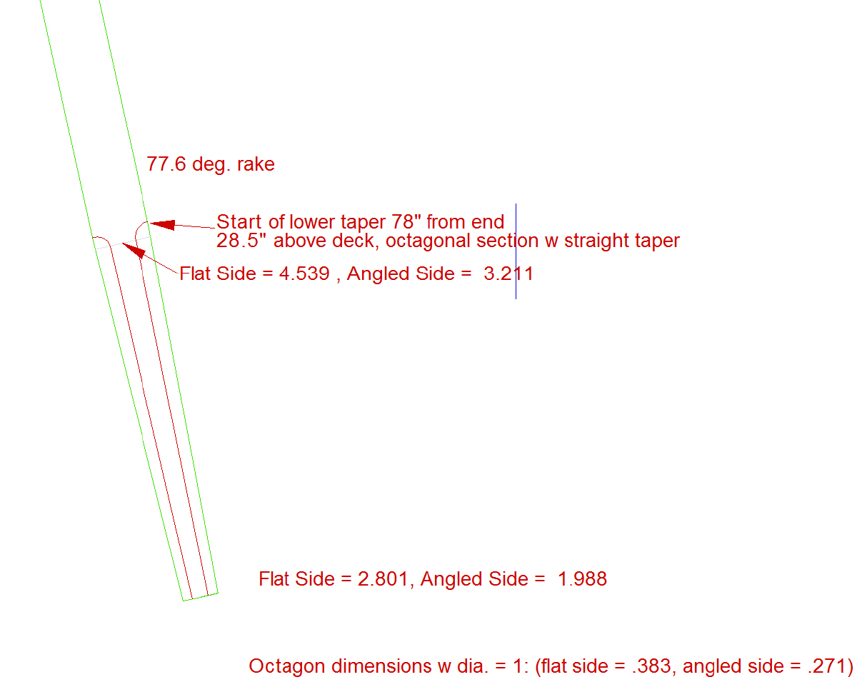
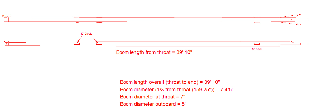
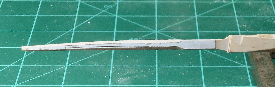
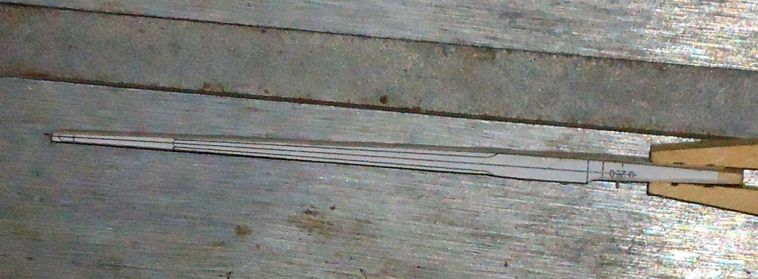
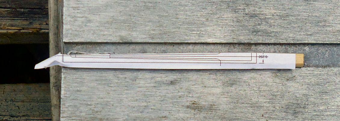
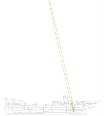
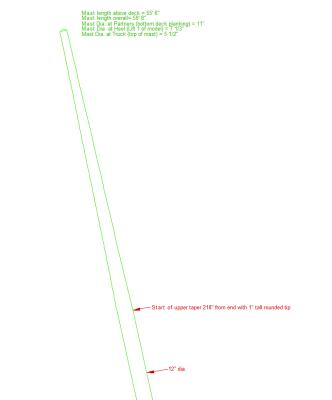
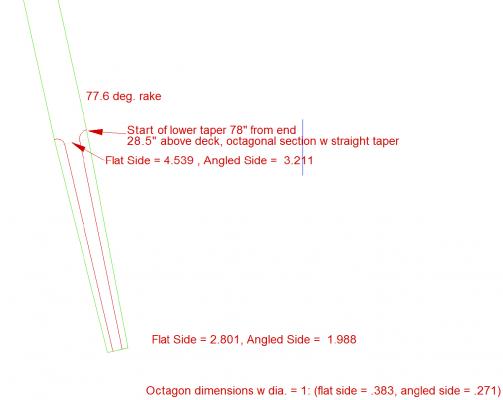
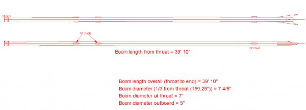
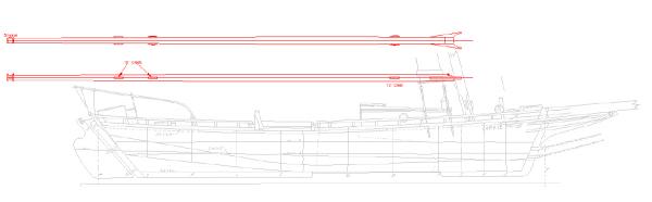
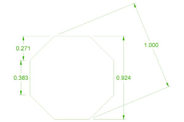
Part 13 I finished the drawings for the mast and boom. The drawing of the Carrie price’s mast was, I felt, too crude for me to just draft off of it. With the original scans being from a page in a book, the lines were quite thick. Luckily the Maryland builders generally followed the same proportional rules when building a boat. Knowing this I took the scans from my Willie Bennett kit, which have about 4 times the resolution, and used them. When I rescaled the Bennett mast to match the length of the Price mast, the diameters fell very close to what was given in the book for the Carrie Price. So using the Bennett as a guide I drew the Price’s mast. To simplify the mast somewhat, I chose to keep it untaperd for part of its length, tapering it at the ends. In real boats the mast was tapered its full length, using a formula that kept it close to the same diameter in the center section, but still tapered. It was not a straight taper, but a curve that increased in taper as you went down the mast. This taper was only fractions of an inch in the center section. I could not find that general rule, and in 1/64th scale, I think it would not show. I’ll just sand in some additional blending when I've mostly finished the part. The upper taper starts at around 218” in full scale. The bottom starts were the octagonal section is. This is a straight taper. The upper one is slightly curved. The main section is 12 scale inches in diameter. I will taper the lower section the full length, even though most of it will not show. This is easier than trying to keep the section below decks a cylinder. I will fit a block in the hull for the lower end to sit in. I will also have to redrill the deck opening. The original plastic mast had a knee at the deck joint and the lower section fit vertically into the hull socket. The mast is 55’ 6” long above deck. Here is a close up of the upper section showing the taper. Here is the lower end. This is a diagram of the faceted sides of an octagon, and how they would look in a side view. From the side the flat section would appear .383” wide if the mast was 1” in diameter. The angled side would appear to be .271” wide. For the 12” diameter at a point on the mast each number would be multiplied by 12. Notice that because of the taper I scaled each end and then connected the points. When I glue patterns to all four sides I can cut down to the lines, and the angled faces will come out the right width, like I did on the bowsprit. Because the bowsprit curved I had to used several points along the length, and connect the points with curved lines. The book gave dimensions for the boom, and when I used these the curve fell onto the plan lines, so I drew it using the plans. The deck and profile page did not have the boom shown, so I copied it from the sail plan when I finished. As you can see, with the long boom and mast, these boats had quite a spread of sail when working. The plans did not show an overhead drawing of the boom, but the Willie Bennett did. It showed cleats on both sides, so I that is how I drew them for this model. The sheave on the outboard end of the boom is for the topping lift used to support the boom when the sail is down. It also supports the boom while lowering and raising the main sail. The end is belayed to the starboard rear most cleat. The line runs from the top of the mast, around the sheave, under the boom, and then it is secured to the cleat. When sailing this line is loosened. In an article I read on the Grand Banks fishing schooner Elsie, the author said that these long booms sagged on the real boats, and that is how he modeled his. I considered it, but decided that the average person would look at a sagging boom as a modeling mistake. Also the curve in the bowsprit was a pain. So a straight boom will be modeled.
-
A member asked me about where I got my information on dredging operations. I sent him a reply, and thought that the others following this thread would like the links too. This is the message I sent. Here are some links. I looked them up this morning. Fishing and Fisheries: http://celebrating200years.noaa.gov/rarebooks/fisheries/welcome.html Kathryn: http://www.loc.gov/item/md1454/ E C Collier: http://www.loc.gov/item/md1454/
-
https://www.warhistoryonline.com/war-articles/murmansk-cruiser-never-gave.html?utm_medium=social&utm_campaign=postplanner&utm_source=facebook.com&src=fba&type=int&page=who
-
- 4
-
-
I know, but I did not have one handy. Mine is lost somewhere on the workbench. I'm not the neatest worker.
-
That's what I did for the pattern on the plastic stem, the glue dissolved after a few minutes. Then I washed it with soapy water. For the wood bowsprit I sanded, it did not take much sanding, I used a very thin coat of white glue. I was worried that soaking it might cause it to warp. Thank you for the suggestion, though.
-
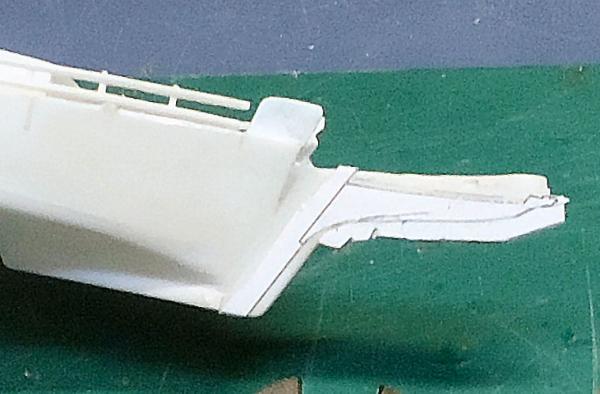
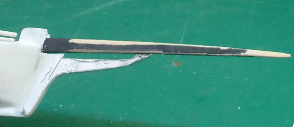
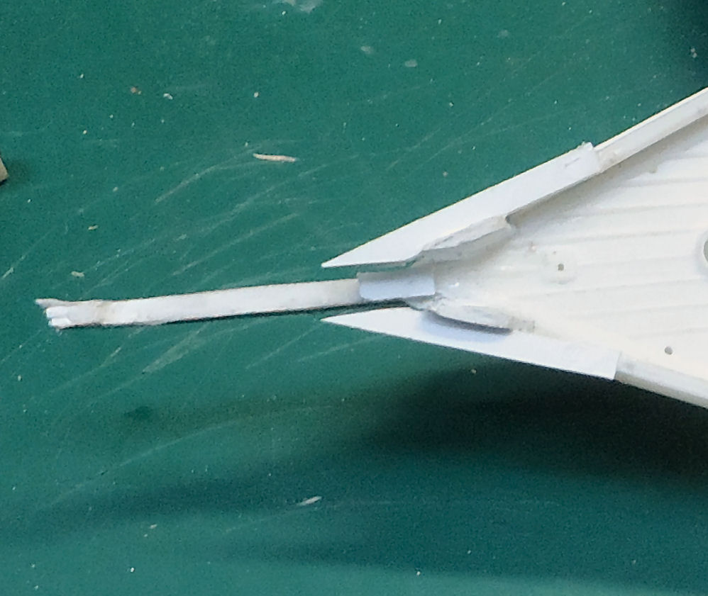
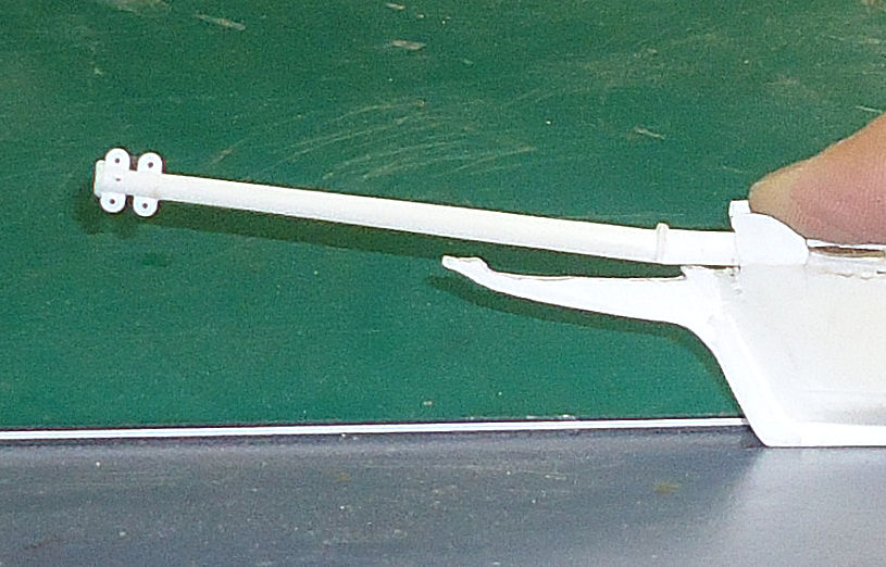
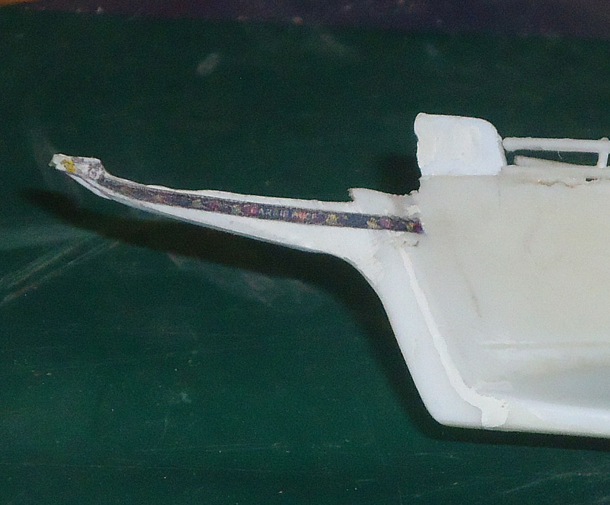
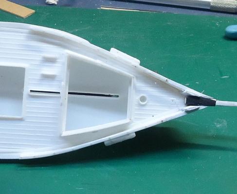
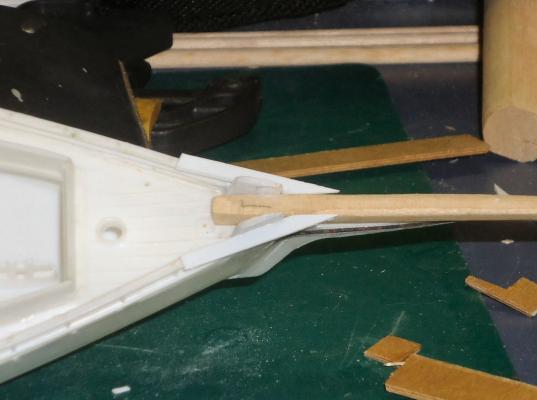
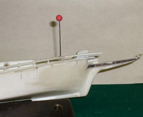
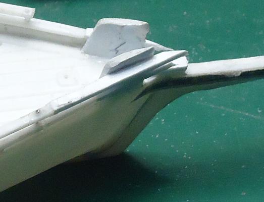
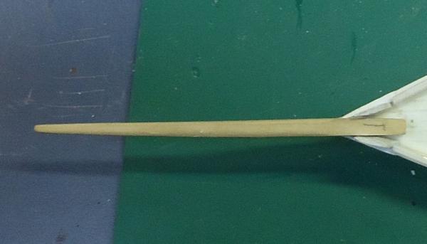
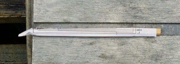
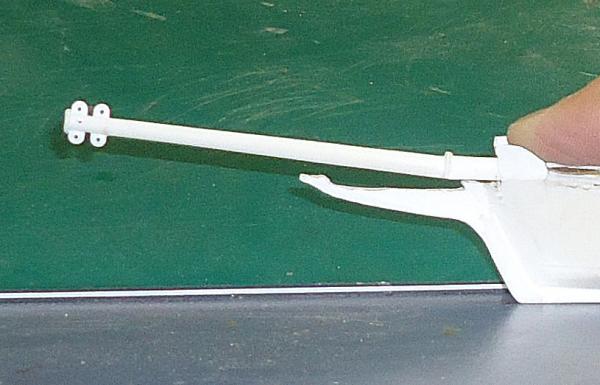
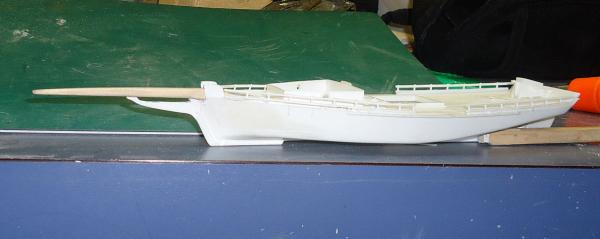
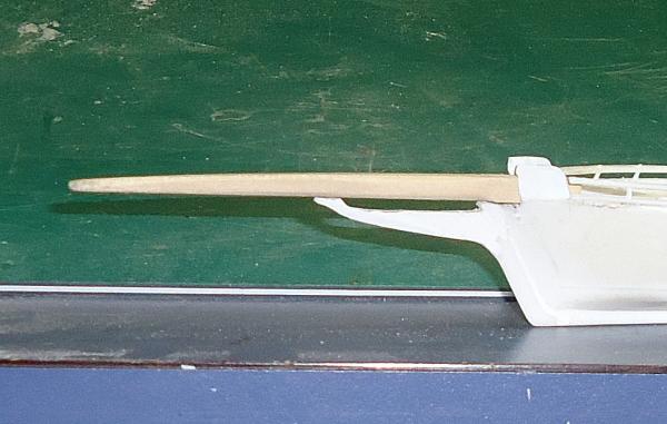
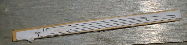
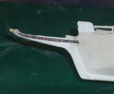
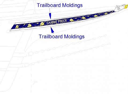
Part 12 Now on to the new bowsprit. I glued the pattern of the top of the sprit, and disk and hand sanded one side. Then repeated this for the other side. I then glued patterns to the other three sides. The side view pattern is shown below. I then shaped the top and bottom of the areas. Next the part was clamped in a small vise, and I beveled the first corner, using a new Xacto blade as a scraper. I watched both sides of the bowsprit to get it even. A little touchup with sandpaper and I was ready for the other corners. Here is the bowsprit beveled on all corners. The transitions from the square to octagonal sections are now even, and where they a suppose to be. The patterns were then sanded off, and using a piece of sandpaper held in my fingers I rounded the end of the part. Below are two pictures of the bowsprit placed on the boat. Here is a comparison photo of what the old bowsprit looked like when placed on the boat. That is just the tip of my finger shown in the photo. The model is small, and this is fiddly work. Next I printed out draft copies of the trailboard, and glued them to the hull. I glued them on in position, so that I could see if they fit, after all this, and so I can locate the position of the molding that goes above and below the trailboards. As you can see I still have a little shaping of the stem below the trailboards to do. I did not notice this until I saw this photo. The area where the stem turns to go down the front of the hull is not completely even. The divot on the bottom at the forward end is the paper of the starboard trailboard. I left the molding border on that one. It will probably be a couple weeks before the next installment. I have other, non ship building, commitments.

-
Frank Despite living in Baltimore for 14 years, I never saw a skipjack in person. Wish I had before I had to move. I hope you get to she her.
-
In the future I plan to scratch built the Carrie Price in 1/32, to match my Willie Bennett kit. 1/64th is small.
-
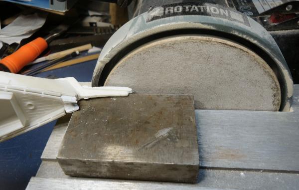
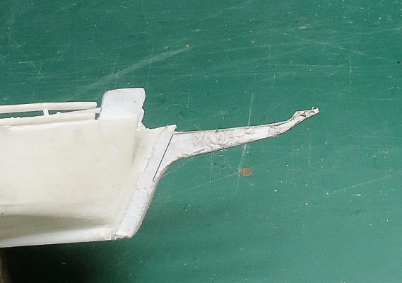
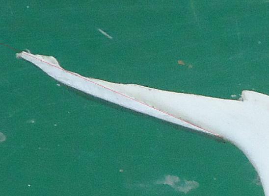
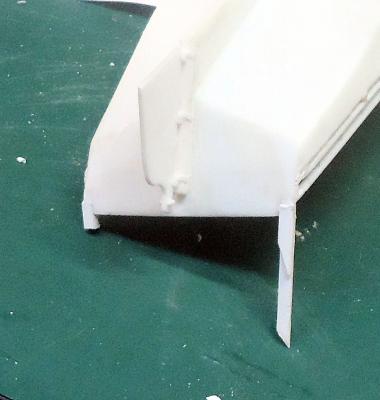
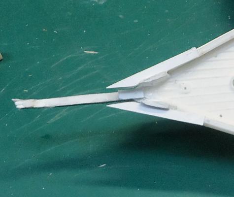
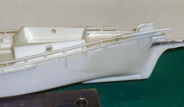
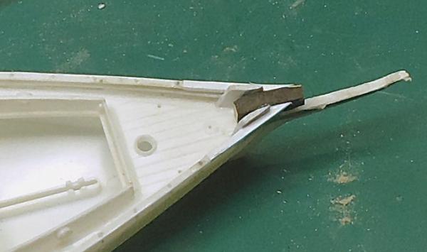
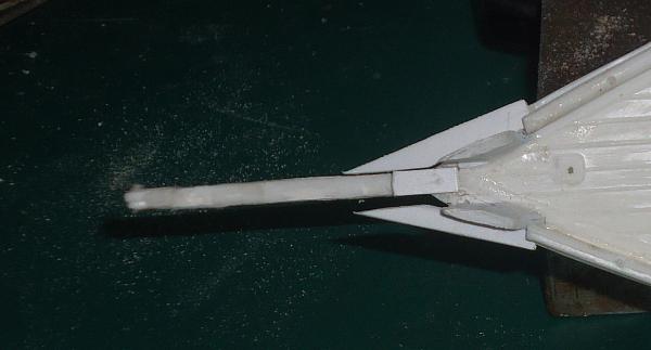
Part 11 I decided to shape the stem before puttying it. It would probably have cracked while I was shaping the piece. I glued a paper pattern to the stem, and let the white glue dry over night. I removed the bulk of the excess plastic with wire cutters, and sprue nippers. Then I cleaned it close to the bottom line with my disk sander. I used a metal block to raise the stem high enough for the hull to clear the table. Unfortunately I glued the pattern to the wrong side, and had to sand it on the side of the disk that cuts upward, and does not have the clearance notch in the shield. Live and learn. I staged this shot to show how I held the piece off the table. I actually had to sand on the other side of the disk. This made extra work, as I could not get in as tightly to the wheel as I could on the correct side. I also trimmed the front of the lower stem to match the pattern. The plans show it as being thinner front to back. After shaping this is what I had. The photo below shows where the old and new meet. The new portion is below the red line. As you can see most of the forward end is new plastic. Here is the first bowsprit placed in position to test the fit. It still sits a little high at the front, but I left a little stock on the stem for final fitting, once the final bowsprit is finished. Next tasks are to putty and sand this, and making the, hopefully, final bowsprit. I also have to figure out how I am going to built the, very tiny, trailboard moldings that go above and below the trailboard.