thibaultron
-
Posts
2,952 -
Joined
-
Last visited
Content Type
Profiles
Forums
Gallery
Events
Everything posted by thibaultron
-
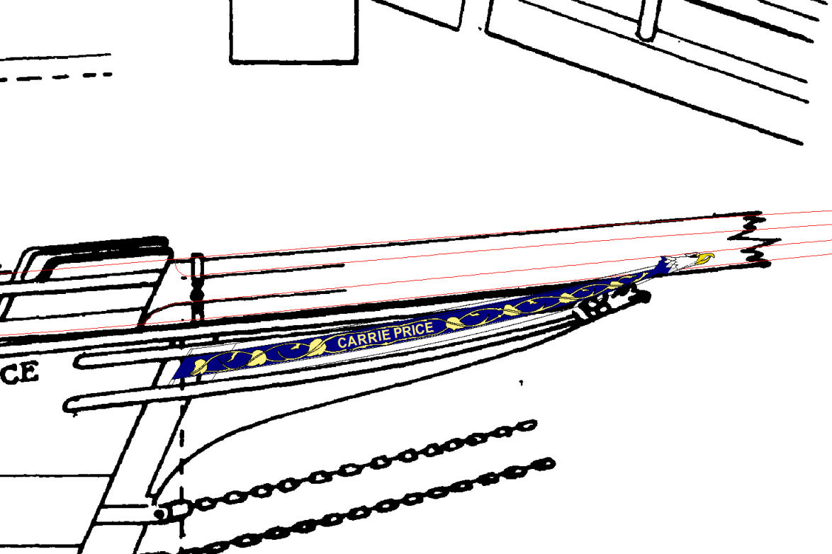
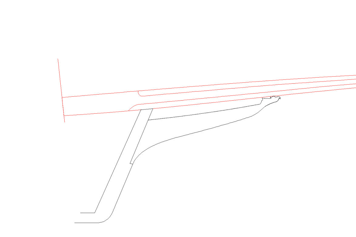
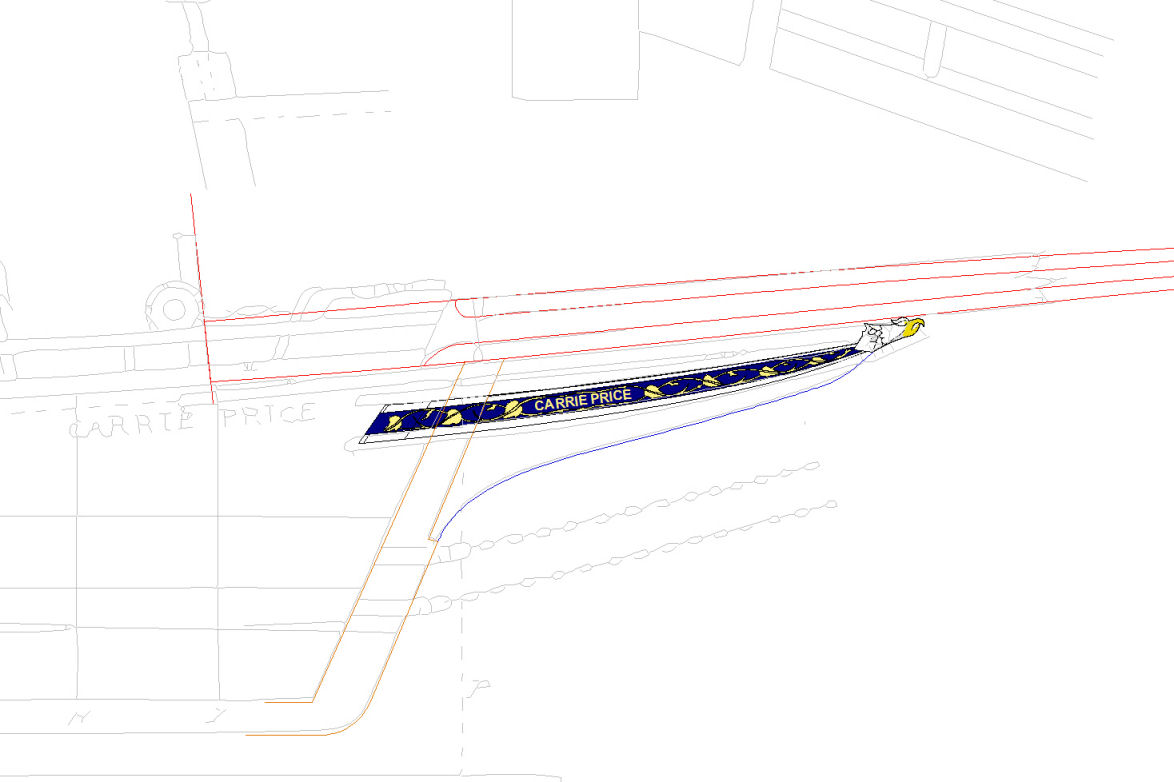
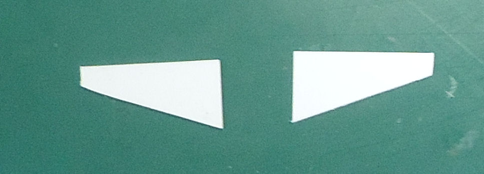
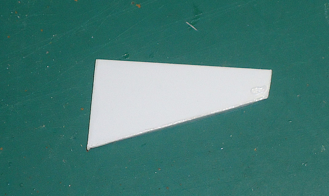
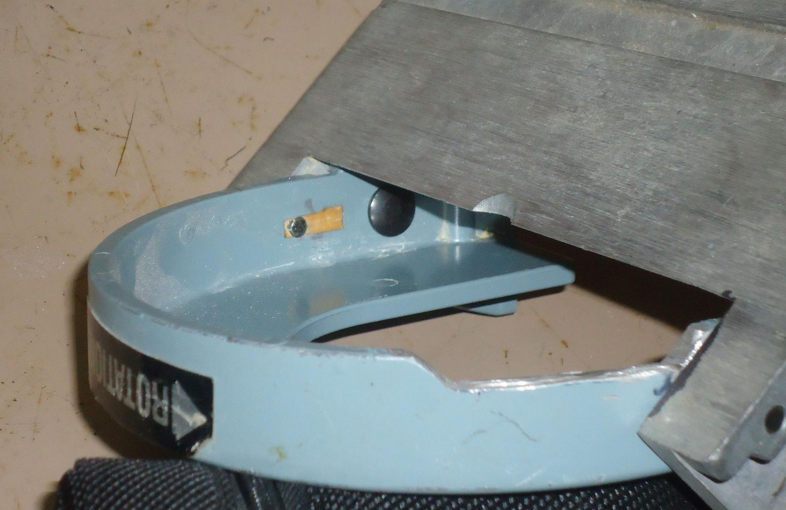
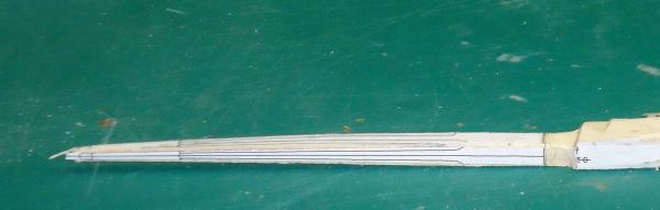
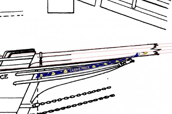
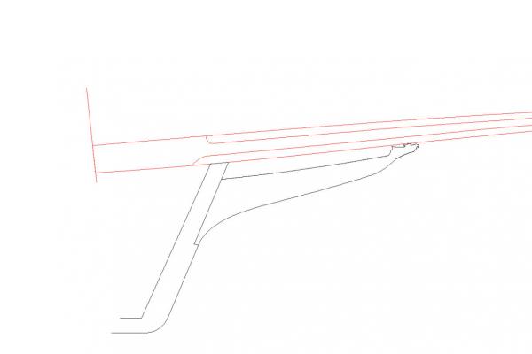
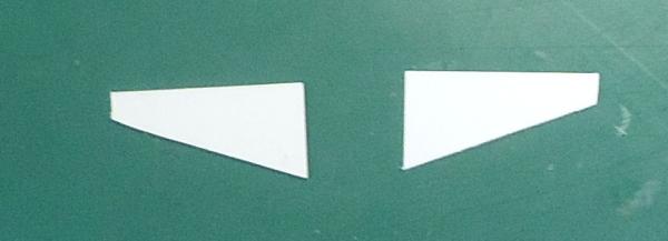
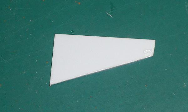
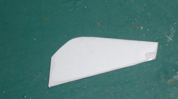
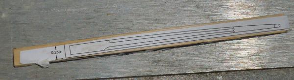
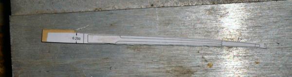
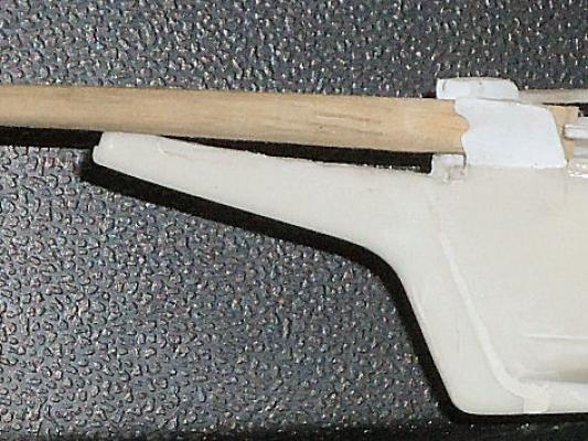
 Part 10 As it turns out I also messed up my first bowsprit. After looking at it closer in sunlight, I noticed that I had not cut the bevels on the octagonal section evenly. One of the top bevels extended too far into the square base area. I used a black marker to highlight the flat top of the bowsprit. You can see that I cut the upper bevel in the picture too long. The bevels were also not completely even, but I could have lived with that, but these upper bevels end right where the rails tie into it, so that mistake would be quite visible. So I decided to start over. I shaped a new blank for the top and side profiles, Then I glued patterns to all four sides. When I cut I can see what is happening on both sides of the bevel. Once again I’ll scrape the bevels. I mentioned that the bowsprit was sitting at too high of an angle, so I decided to fix this problem before continuing. It is hard to see if the bowsprit is correct, if you can not get it into the proper position. I made a drawing of the stem, to use as a pattern. I also had to make some mods to the trailboard graphic, to get it to fit better. The main part of the graphic was good, but the eagle's head was too small. I rescaled the head, and rotated the graphic a little to line up with the molding, after correcting the eagle head. Here is the old trailboard. The trailboard is too high at the forward end, it should be supporting the bottom of the bowsprit. Also you can see that the eagle head in the drawing is larger than the one on the trailboard. This is the corrected drawing, with the stem outline. Notice that the trailboard now contacts the bottom of the bowsprit, and that the eagle head is a little larger. This is the stem outline drawing. I traced the outside of the upper trailboard molding to get the top of the stem. After placing a cutout of the stem pattern on the model, I found that the proper lines fell outside the bottom of the plastic at the forward end. Sorry no picture of this, I had both hands occupied with holding the model and pattern. I need to add to the bottom of the stem, to get the right lines. I cut out two pieces of plastic sheet, one .060” and one .040”. The stem is .090” thick on the model. Then laminated them together, and shaped it to fit the model stem. After cutting off part of one side, so that it did not extend so far down the straight part of the stem, I glued the extension in place. I’ll leave it overnight to make sure the glue has dried. The top of the new stem will be just below the old forward bottom edge. I have to putty and sand, putty and sand, etc. before I start to shape the part.
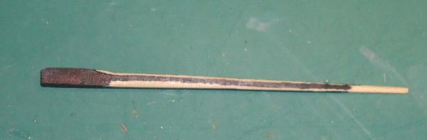
-
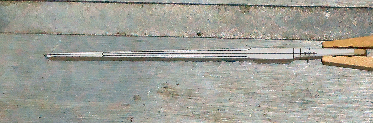
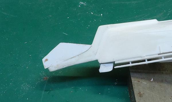
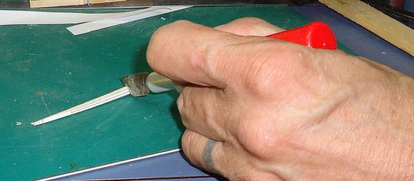
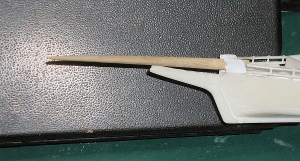
Part 08 After messing up the 2X size practice bowsprit, I decided not to make another practice piece. So I went on to sanding the blank for the model bowsprit. Here is the starboard side of the bowsprit tapered. Next I sanded the Port side. I rough sanded on the disk sander, then hand sanded down to the lines. I then glued a drawing of the bowsprit looking from the side (so I had the top and bottom profiles) to the tapered blank. Then I again rough and finished sanded to the lines. To carve the octagonal portion, I used a knife to scrape the 45 degree angled side. This gave me more control than trying to slice or sand this area. I held the bowsprit at a 45 degree angle and scraped with the blade parallel to the table. In this photo I have the blank just positioned using the knife, I’m not holding the other end, as I had to use my other hand for the camera. Lastly I sanded the round section at the forward end by spinning the bowsprit inside a piece of folded sandpaper held in my fingers. Here is the finished bowsprit temporarily placed in position. I’m sorry that the picture is not sharper, the part is small, and my camera is just your average type. If you look closely where the bow, deck, and bowsprit meet, the bowsprit is sitting well clear of the deck. This is not correct. The stem piece is too high at the forward end. I’ll have to reshape it. Next time I’ll reshape the stem, fix the divot in the port knighthead, and work on finishing the railings. The railings at the bow extend to attach to the bowsprit. That is why I had to make it before I could continue with the hull.
-
Yes that is the way the sander is designed, in use the pins always stayed at the top of the slot. The slot was just so you could remove the table.
-
It never worked the way before. The distance between the table and disk is adjusted by sliding the shield back and forth in slotted mounting feet. The center of the circle formed by the angle adjusting bolts and the hinges, is the center of the hinge pins.
-
Work will resume at the beinging of the month. I've done the modification to the disk sander shield (see link below), and progressed far enough on my workshop remodeling, that I can remove the boxes and such from my work bench. I'm going to FL next week, and will start work back on the model the first of Aug. http://modelshipworld.com/index.php/topic/11014-modifications-to-a-dremel-beltdisk-sander/
-
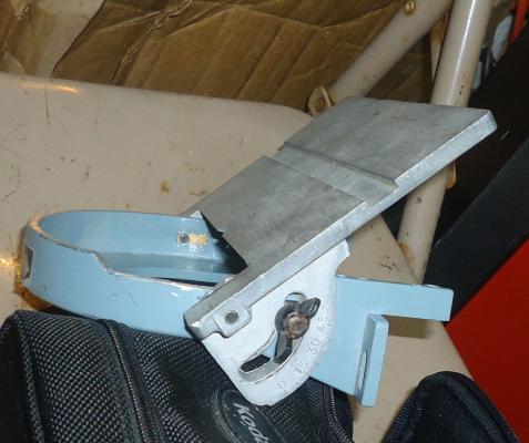
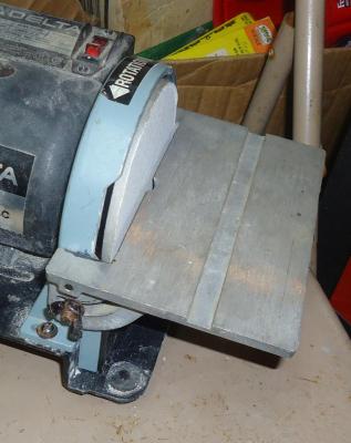
While trying to sand the bowsprit blank for my skipjack model, I ran into a problem. The shield on the disk sander part of my Dremel Belt/Disk Sander projected past the edge of the disk, making it impossible to sand an inside corner, as shown at the left in the photo below. You can see that I was unable to sand up to the end of the piece. Also the mount for the table was not stable, it moved out of the angle setting under even moderate pressure. I decided to cut out part of the shield, so that I could get to those corners, and see why the table was moving. During disassembly I found that not only were the hinge pins split pins, that can compress under pressure, but also that the hinge hole in the shield was really a slot! The slot allows the table to be slid down and out once the clamp bolts are removed, not a feature I need. I’d rather have a nice tight fit on the hinges. So I modified the hinges by filling the slot, and drilling the hinge points for the next size 3/16” solid pins. I wish I could have filled the slots with metal, but I did not have any scrap that would not require massive amounts of filling to get small enough. The drilled holes for the pins would cut into the sides of the slots, so I feel that with the hardwood plugs I put in the mount will be strong enough. When assembling the parts, I used medium strength thread locker when iserting the pins. Any way here are pictures of the modified shield.


-
Here's an interesting site I found, on the history of the USS Arizona. https://www.warhistoryonline.com/war-articles/the-uss-arizona-life-and-death-of-an-ill-fated-battleship.html
-
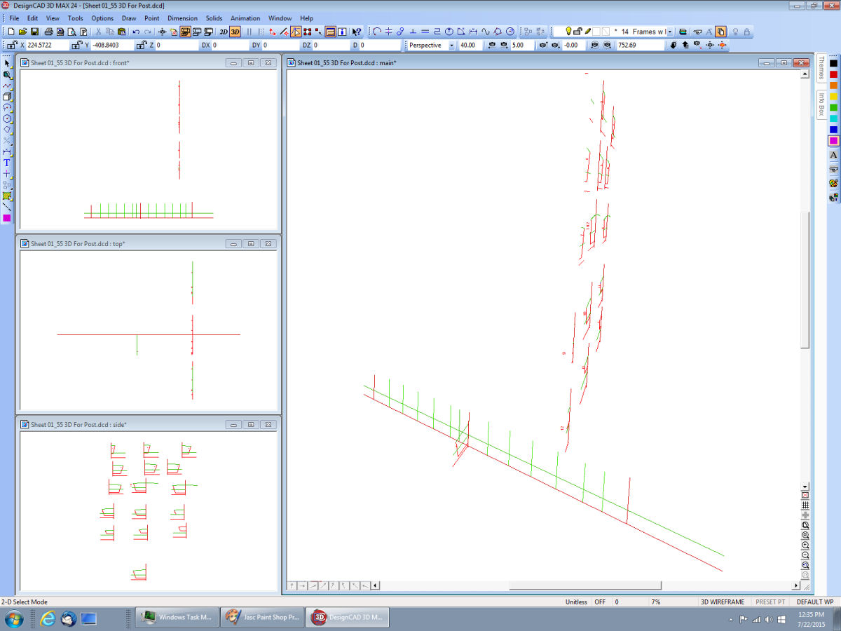
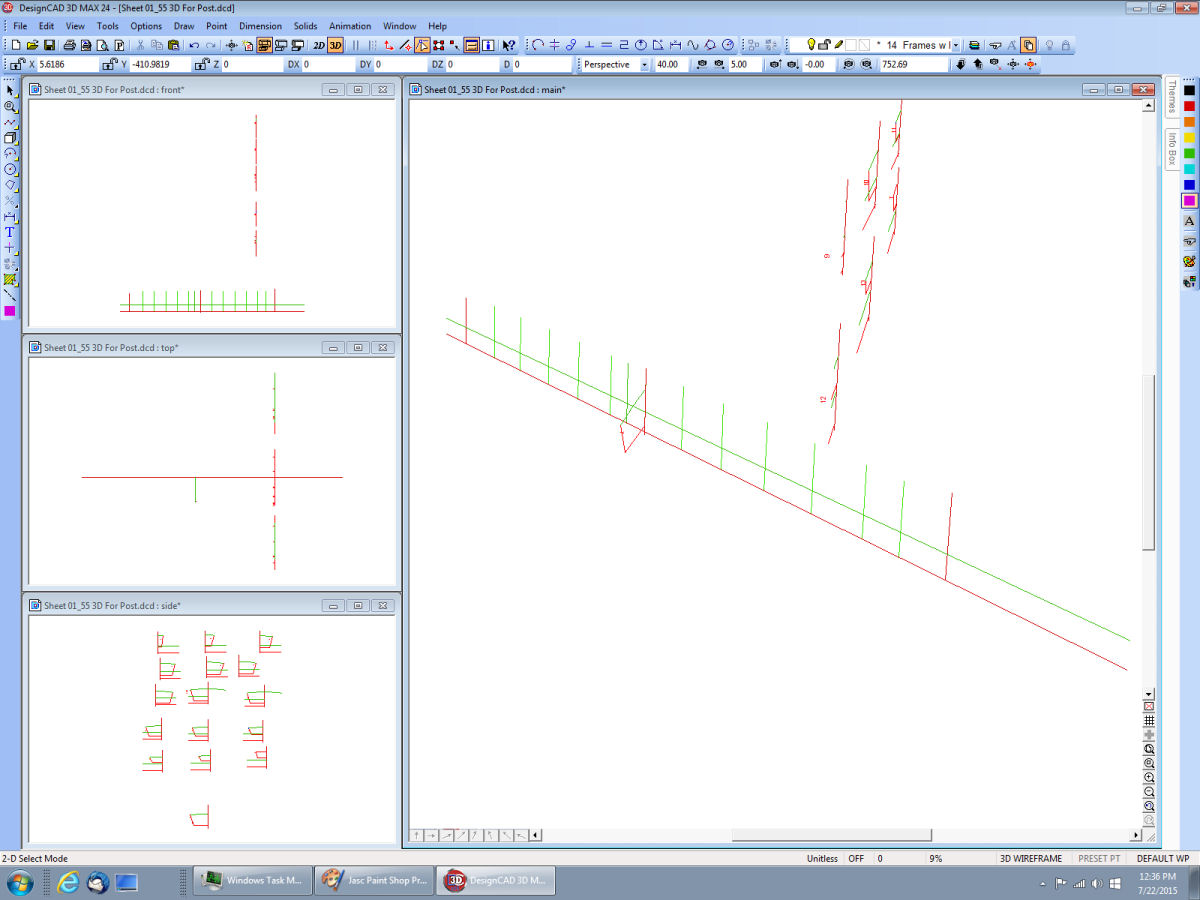
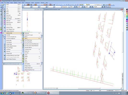
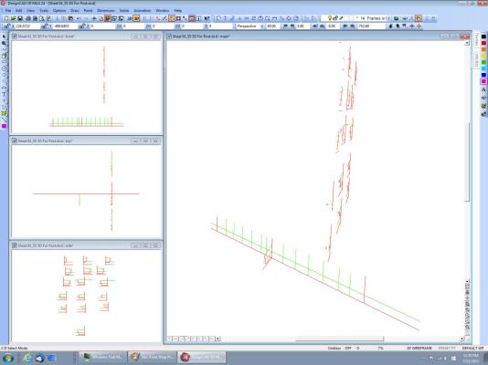
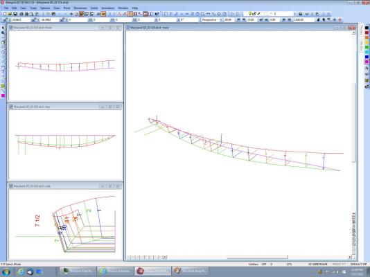
Part 3 of 2D to 3D Deselect the original and select the new frame, at the crossing of the baselines (shown by the solid dot after selecting.) I have restored the 3D windows, and I’m getting ready to move the frame into position. With the “Move” command (see menus in picture). After you select “Move” the frame will be shown with black lines to show where it will move to, if you click the mouse. The original frame is shown still in place, until the “Move” operation is completed I then selected the crossing of the baseline, and station for this frame. I’ve been using the “Point – Intersect – 1” (or F4) to select all these crossing points. This completes the” Move” operation, The frame has been moved so that the point used to select it (the baseline crossing point), has been placed on the second point selected, the baselines station crossing. Here is the frame after I zoomed in a bit. And a bit more. Here I’ve removed the station line. The rest of the frames are moved in the same way. Note that in this earlier drawing, I had already drawn the keel line, and I am using that as the final move point, thus I did not have the baselines in these frame drawings. The way I show in this post is better. If you look you can see I have a problem, as the frame waterlines are not matching the reference waterline. This is from the original drawing I made from the scanned book page, before I bought the full sized drawing. After all the frames are in place you can remove the frame baselines. Before you do, look at the other views and make sure that none of the frames is out of position.


-
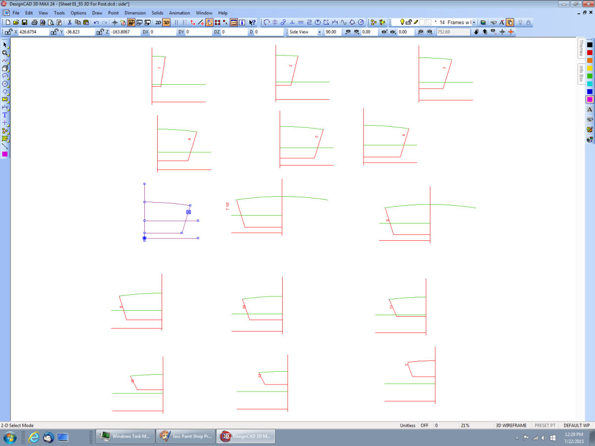
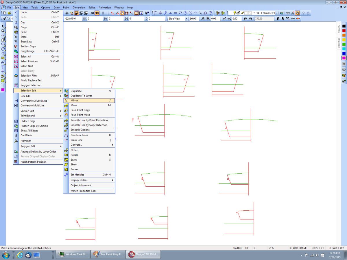
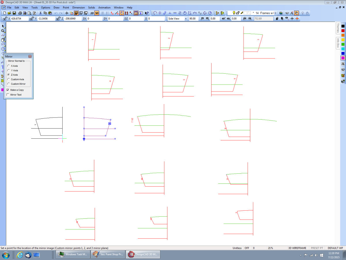
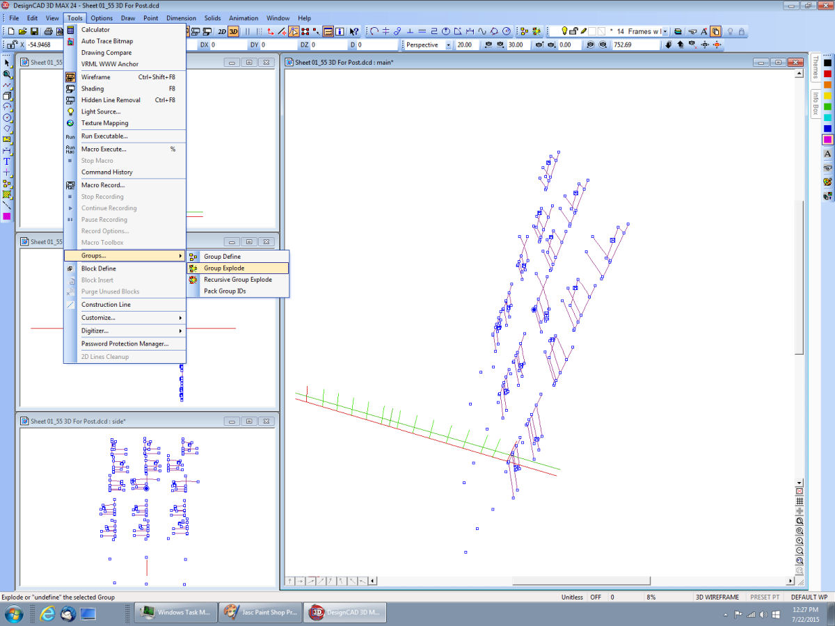
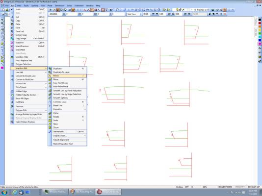
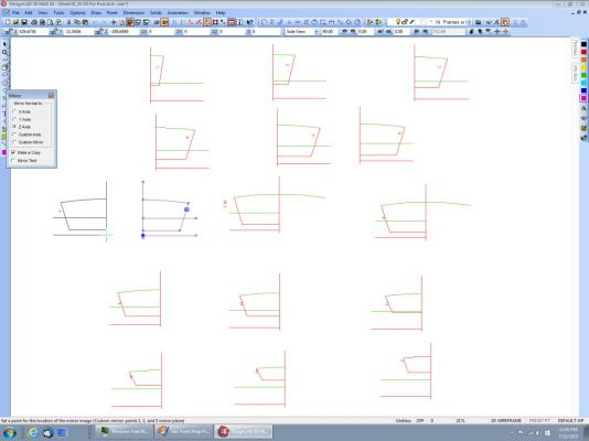
Part 2 of 2D to 3D This is the front view window expanded. We need to change the frames from the group we made earlier, so that we can move the individual ones. Select a point anywhere on the frames, and going back to the “Tools – Groups menu select “Break Group”. Now I have selected just the lines for one frame, and made them a group. Note that the solid dot is in the middle of the frame, this means that the group was selected by clicking somewhere inside the group boundaries. The frame is pointed in the “wrong” direction, I am placing all the frames on the starboard side to build the hull, and this one would end up on the port side. Deselect the frame group, and reselected it at the crossing of the baselines. Now I have to mirror the frame to reverse it. The above picture shows the menu selections to do this. As this is the front view I have to mirror it on the Z axis. I generally pick the wrong axis, and have to redo it until I pick the right one. I use the “Make A copy” option, that way I’m not risking the original, if I make a mistake. The black frame is the mirrored copy, that is displayed when you move your cursor off of the menu box. The mirrored frame will move with the cursor, until you click the mouse, then it will be dropped on the drawing where the mouse was. There is the mirrored frame. If the original was a group the mirrored one will also be a (separate) group.


-
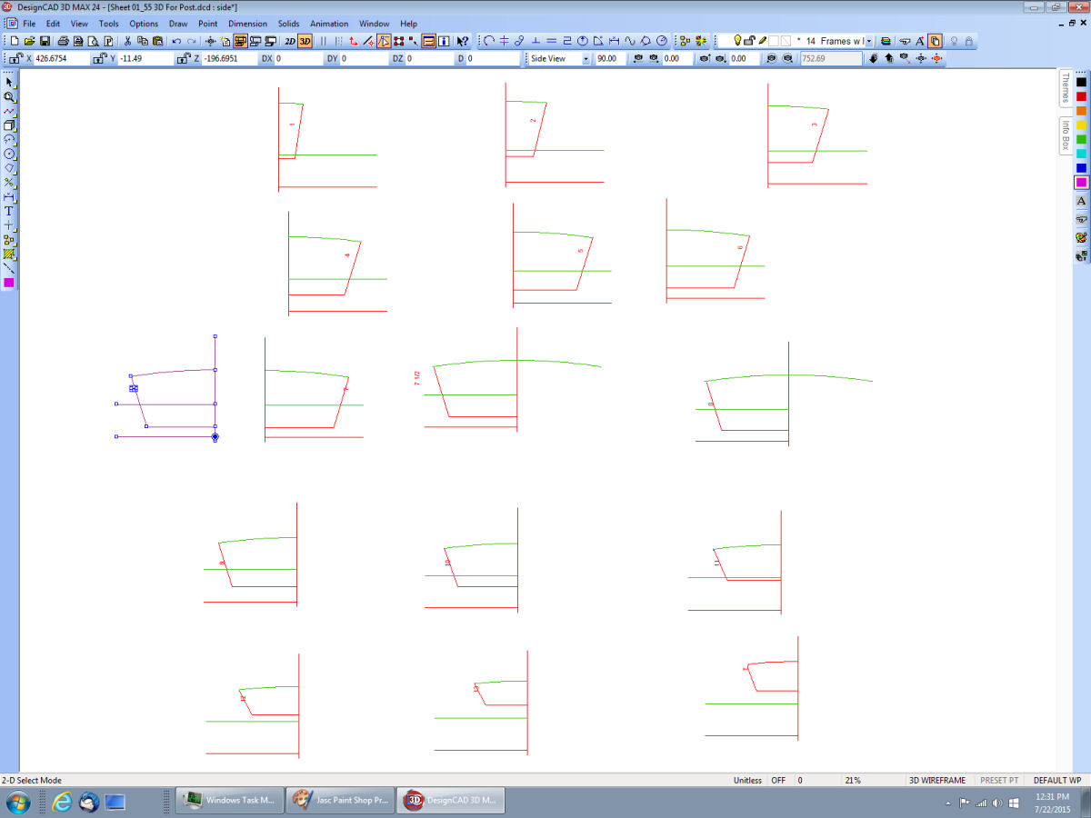
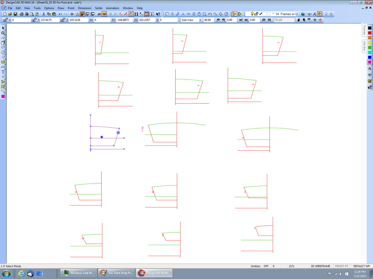
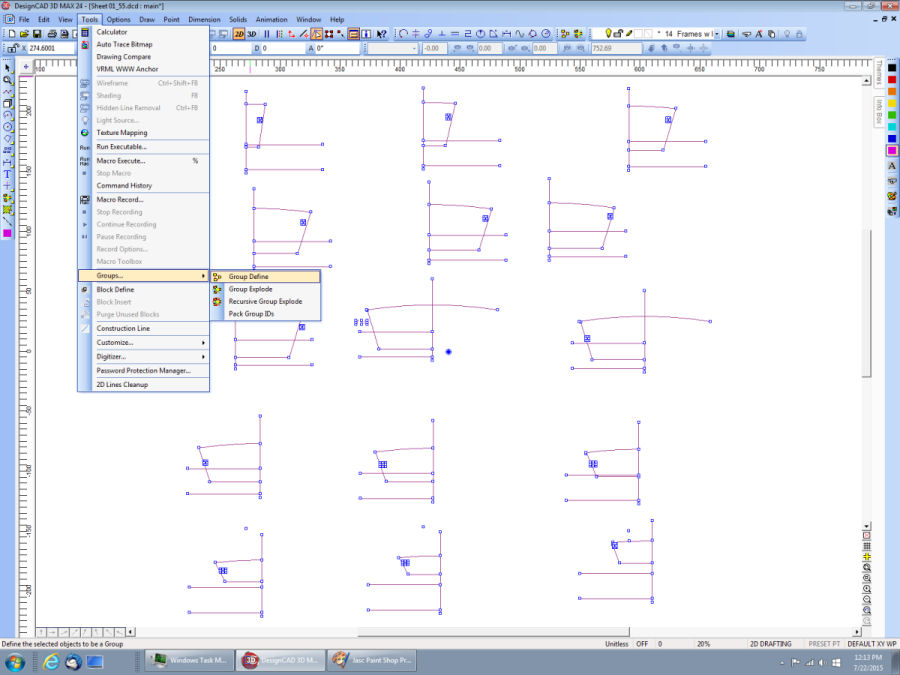
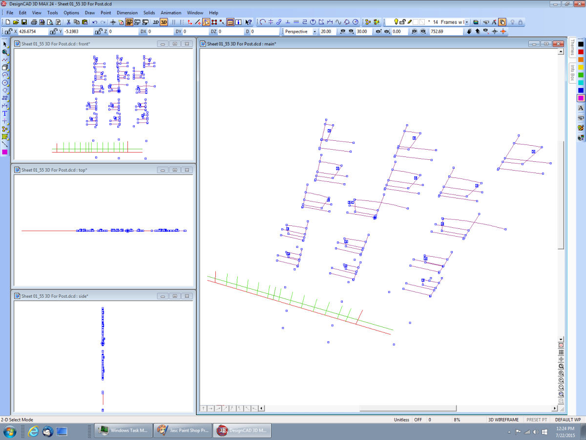
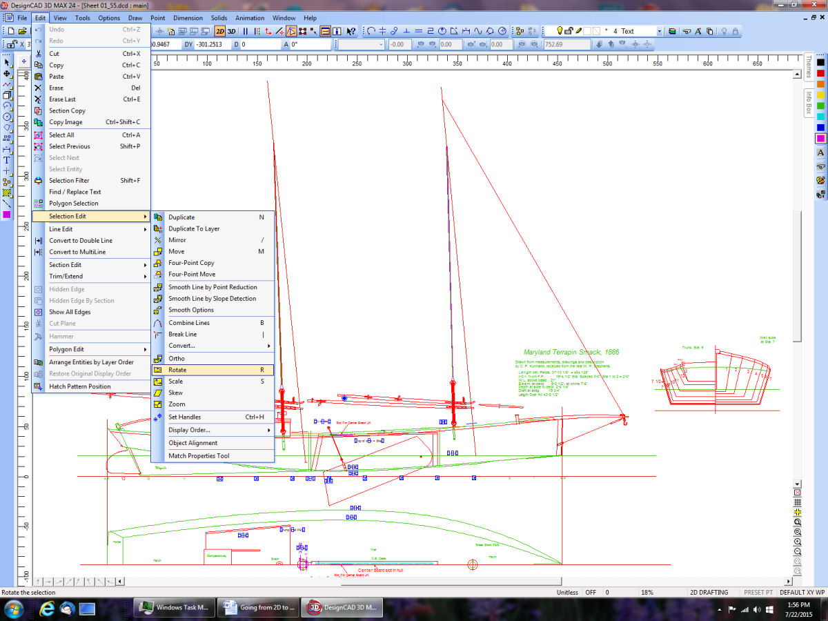
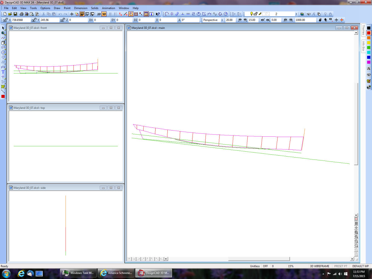
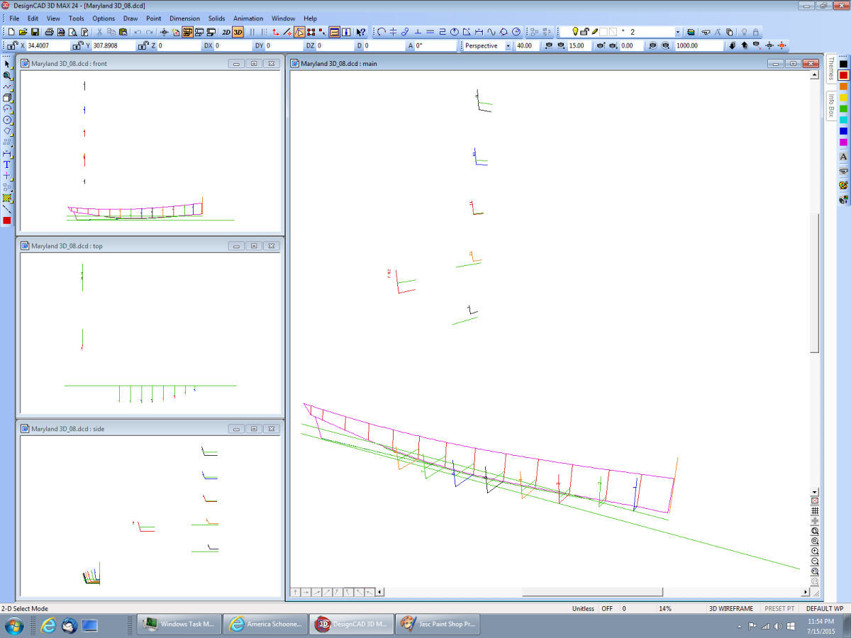
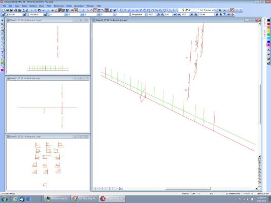
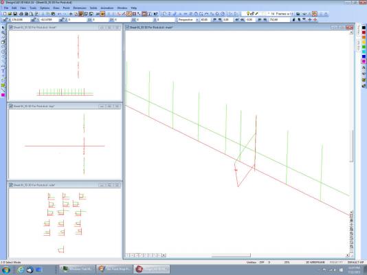
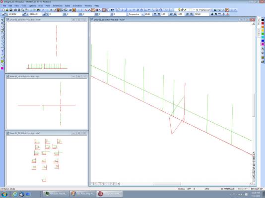
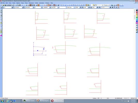
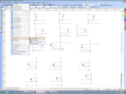
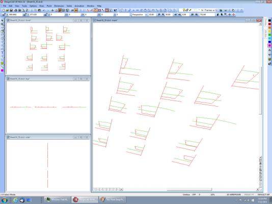
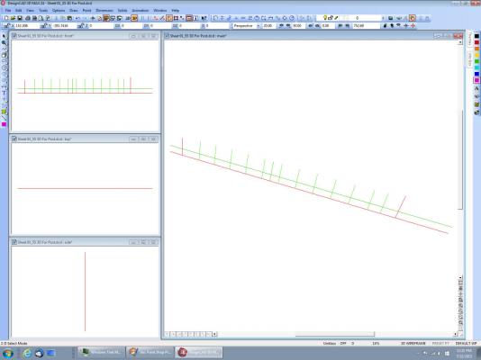
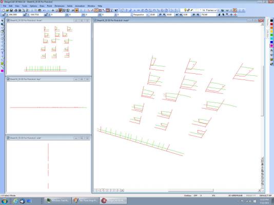
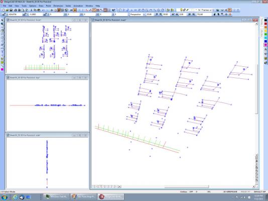
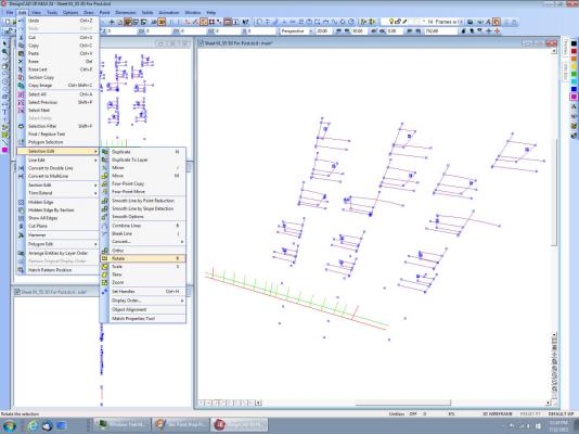
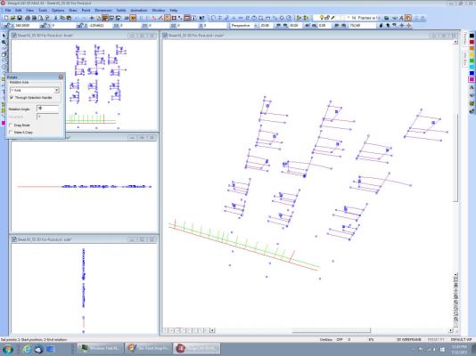
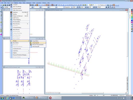
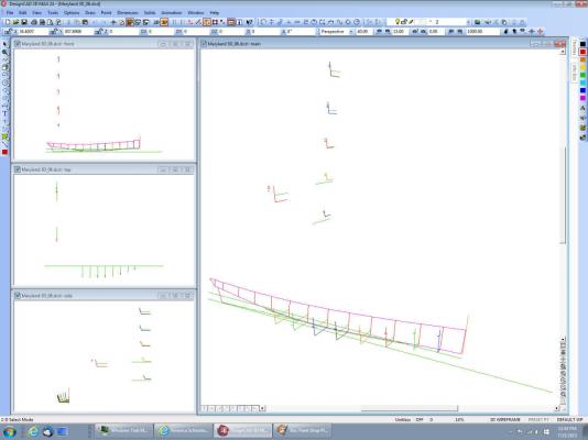
Going from the 2D drawing to a 3D drawing. This will be in at least 2 parts, as I have too many drawings to fitt in one post. Above is the drawing I’m going to start from. I have developed the frames on the upper right to individual frames, on another layer, as part of this drawing. Here is the layer with the frames. I have selected them all, and am making them a group, using the menu selection shown. Making them a group makes them basically one thing/entity. The CAD program will act on all of the grouped lines as a single thing, not separate lines. I’ve now gone to the 3D mode, by selecting the 3D button in the menu system. Note that the lines are still in the proper relationship, as shown in the upper left window. The lines look skewed in the main window, because we are looking down and a little to the side. Note the 3D viewing angle settings in the lower right bottom main menu. If all the settings are at zero, the drawing is displayed as if it was a 2D drawing. You have to crank in some values so that you can see the 3D view. The baselines, fore and aft parallels, and the station lines have been drawn, along the XY plain (Z=0). The red lines are the baseline, and parallels. The green lines are the waterline, and station lines. These are actually the ones from the 2D drawing, I’ve just turned on those layers. All the 2D lines you drew will be displayed on the XY plain in 3D. Placing different sections of the drawing on different layers allows you to hide those layers when working on another section. For example the station lines and baselines are on different layers. I hid them when I was working on the spars, to cut down on the clutter on the screen. Once again you can see that they are not skewed in the Top, Side, and Front views. In this picture I’ve turned on the layer with the completed frames. The curve lines are the deck, with the camber. Here the frames are all selected, and made a group. I have also made the baseline, etc. a separate group. I cleared the selection, and reselected the frame group, at one of the intersections of the baselines. The selected point is the solid dot. The square boxes are the individual line end points. There is an option in the “Options” menu “Point Select Mode” that turns this on and off, if you don’t want it. I forgot to save the screen when I was rotating the frames, so the above drawing is the main one. I selected some lines, and am getting ready to rotated them. This picture is to show how to get to the rotate command. When you select rotate this new menu window pops up. We want to rotate the frames to be perpendicular to the baseline, so select rotate around Y axis, enter 90 deg. For the rotation angle, and deselect the “Drag Mode” option. Now when you move your cursor away from the box, it will be displayed as a curved line and arrow symbol. Move the symbol to the main windows, and click. I could not get the screen capture to show this symbol. The frames have been rotated, and the frame group is being broken, so that we can work on the individual frames.
-
Nice looking boat and kit. Looking forward to your build. Is there any history on the boat? Country, year, use? Are the instructions in Russian, English, both, or other?
-
I posted the drawings in a previous post, refer back to them for this post. I draw the keel and/or fore and aft baseline in the XY, marking the station lines along this line going from the baseline up in the Y direction. Then I paste in the frames/hull stations, which will be shown laid out in the XY (facing you). I rotate each frame around the Y axis, so that it is now in the XZ plane, perpendicular to the keel/baseline. Then move each frame to its corasponding location. I'll post a step by step tomarrow, its 10:20 PM now.
-
In DesignCAD You can try Control-Shift-R. This will refresh all the screens, not just the one you are on. Or Control -Shift-W, this will resize the drawing in all the windows to fit the entire drawing in them. If you lost one of the 3D window panes, the menu option "Windows", "DesignCAD Tile Settings", "Restore DesignCAD Tile" will restore the screen to the 4 windows of the standard 3D setup.
-
In an earlier post someone mentioned that their CA was not bonding parts. I had this problem with a bottle of CA. It would go on the surface, but when you pressed the parts together, nothing, even though the glue was "wet" when the parts were pressed together, and "dry when I released the parts.. I bought another bottle and it worked fine. There was something wrong with that first bottle. In 25 years of using CA, this was the first time it had failed to bond. I have never had the CA let go of a glued model, but I have found it to become brittle after time, and fail after a hit on the model sometimes. This was on RC ships that take a beating, and have less ribs than would be typical of a regular RC hull.
-
The key for us is the use of the word "spline", and the picture of the draftsman using a batten to find or draw the lines. In CAD most programs can draw a curved line along a series of points that don't fall along a straight line. You could use this to draw an osilating line as in the video. This does all that math for you. In DesignCAD they are drawn using the "Draw Lines Curved" command. In AutoCAD "Draw Spline". DesignCAD also has a curve, called a "Bezier curve, but that involves tangents, and I have never used it. This is the type of line I use to trace a sheer, or a frame line. In DesignCAD you can even specify a file with a list of points along the curve, and it will draw the curved line for you. If you have an offset table, these points can be generated from the table. The kicker is that the points in the file must start at one end, and finish at the other. This means determining the flow of the points in the offset table. I generally use a spreadsheet, to manipulate the offset points, into an end to end flow.
-
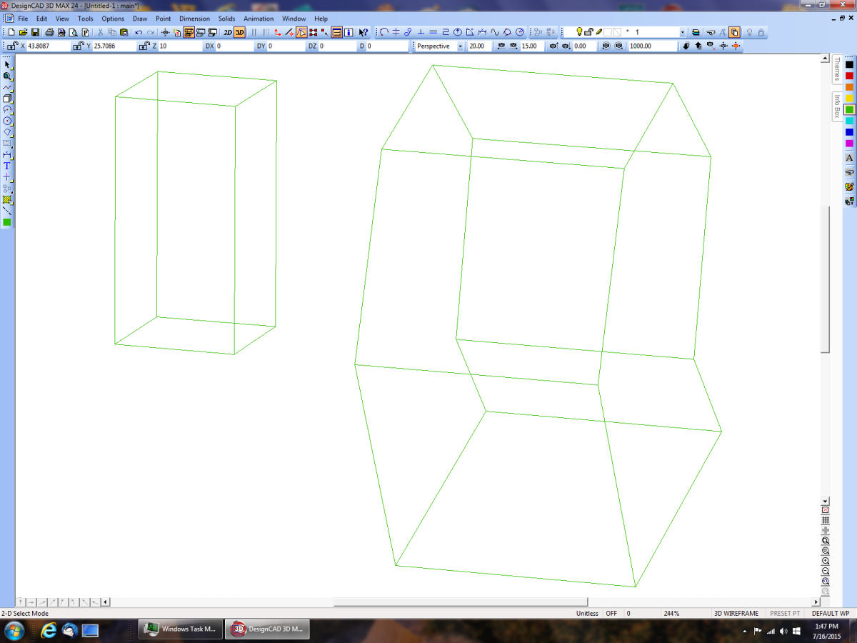
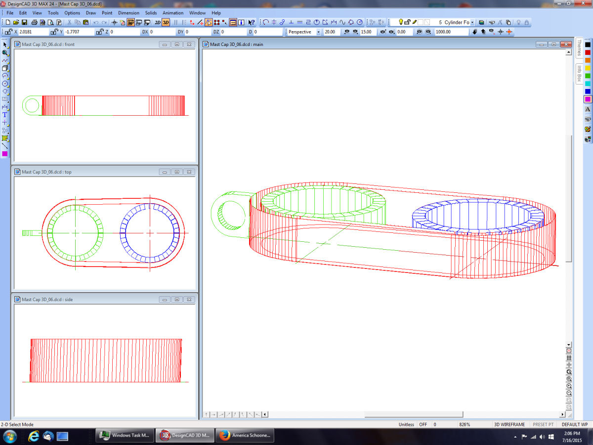
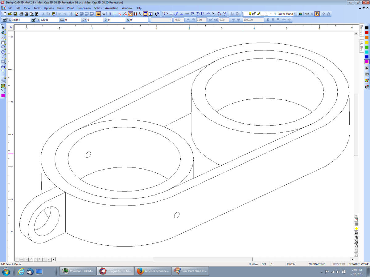
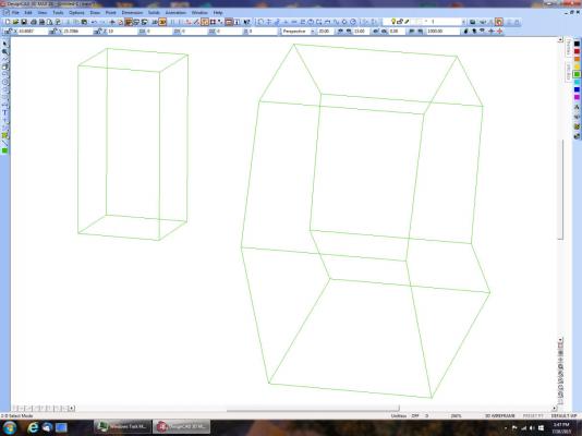
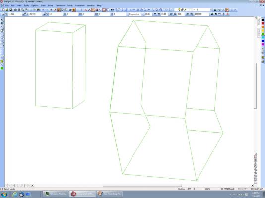
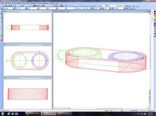
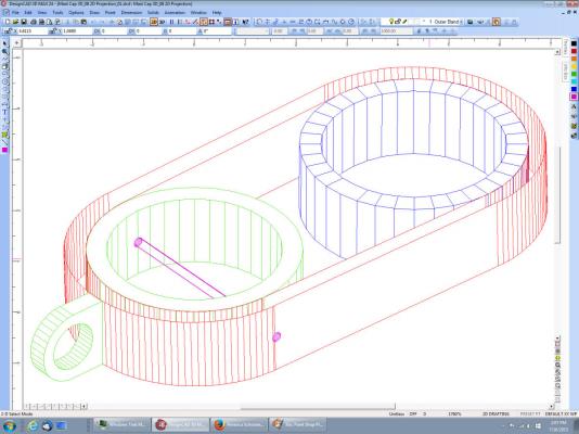
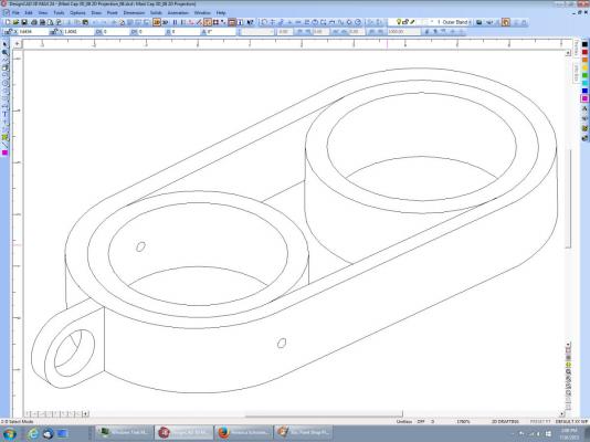
The 3D hull in the above drawing, is not solid, I used surfaces between the frames to give the look of solid, so I could see what she looked like. DesignCAD does not extrude a solid thing. It just make tall 2D walls, with no top or bottom surface, so I can't for example extrude a keel outline to 1/8" thick, and then operate on it like it was a regular 3D thing. The solid drawing shapes like a box or cylinder work just fine with solid add, subtract, and the other operators, but not extruded objects. That is the point I am at now with my new drawing of the boat above. I have to relearn AutoCAD (which I have an old copy of), in order to extrude a solid keel and frames. Then I'll import them into DesignCAD to continue. Why not just use the AutoCAD? It's an old copy, and I expect every new version of Windows to not run it, so far they have, but I'm familiar with DesignCAD, and can afford to upgrade it now and then, I'll never be able to afford a new copy of AutoCAD. DesignCAD is almost as good, just not in the Extrude operation. To illustrate this I have two drawings. The first is a random 2D polygon I generated, then extruded, with a box I made using the Solids menu. The box is of course, on the left, the polygon on the right. The second drawing is the above with using the "Hidden Line Removal" command. The box came out correct, but not the extruded shape. I can save a 2D projection, and remove the extra lines, and have, but I can't just do it automatically. Here are examples of that: The 3D drawing with hidden lines removed. The inner bands are 3D solids – Tubes, the outer band is an extruded shape, notice that the walls of the inner bands were not hidden, as the extrusion has no top surface. The end piece is generated from adding and subtracting solids, and also came out correct. This is the 2D projection drawing, as it was generated. Here it is after I cleaned it up by hand.
-
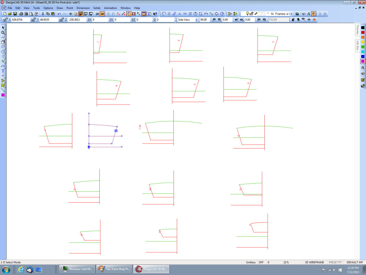
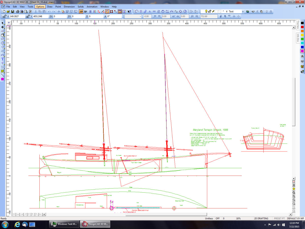
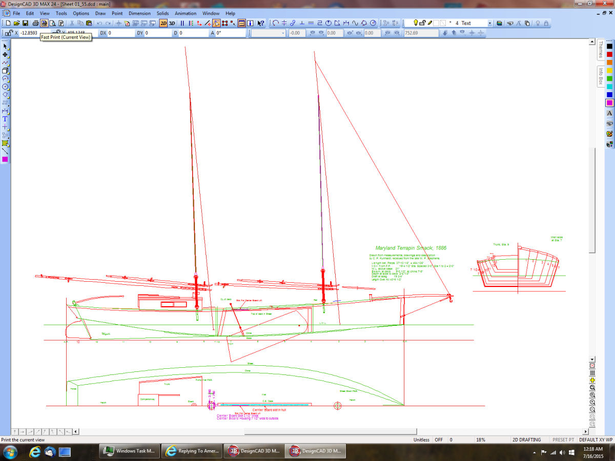
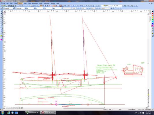
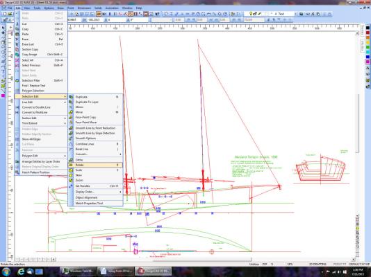
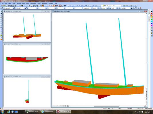
After generating the hull lines, I go to 3D mode, draw out the base line, waterline, whatever you are using to determine the fore aft positions of the hull lines in the X direction. Then I rotated the hull lines 90 deg. so they run in the XZ rather than XY direction. Each "frame' is then positioned at its repective place on the reference line. you now have the 3D model of your hull. The following pictures are screen captures of "The Maryland Terrapin Smack 1886" that I drew: This is the station lines, keel, and deck center line laid out in the X axis. In this I've loaded in the frames, rotated them into the XZ plane, and have move some of them onto their locations. Note that this boat has a flat bottom and slab sides, but a regular curved hull is done the same way. Here the frames and transom are all in place, and I have used a curve line with defining points set at each frame to define the Chine and Shear. Much further down the line, I have added surfaces, deck furniture, etc. These are all half hulls, but all it takes then is to duplicate and mirror the finished side, then stick them together. These drawings were made from a scanned page in a book. I've since purchased the full sized plans, and started over to make a more accurately scaled drawing. I'm just starting the 3D drawings for this. There are many other layers of details that are not shown. At this time I am concentrating on Chesapeake Bay boats, for scratch building future models. In the pasted I've CADed 2D drawings of WWII era ships, for semi-scale 144th scale models (to scale, but lacking fine detailing).

-
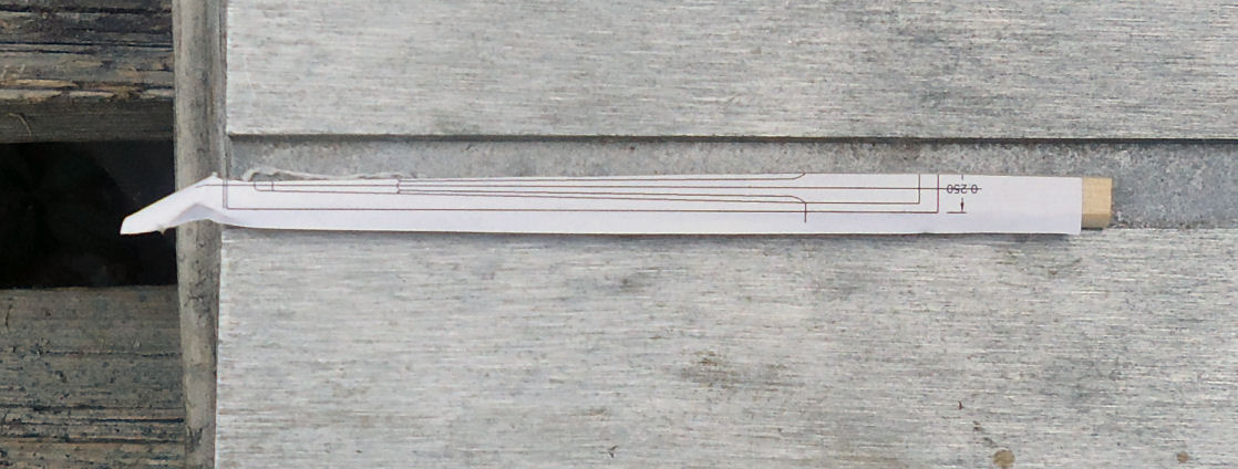
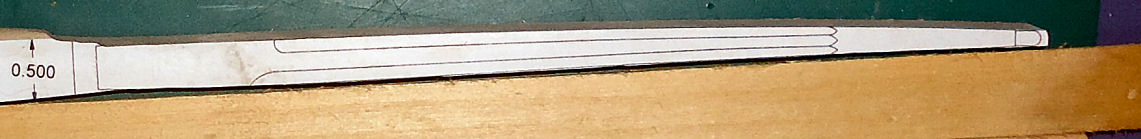
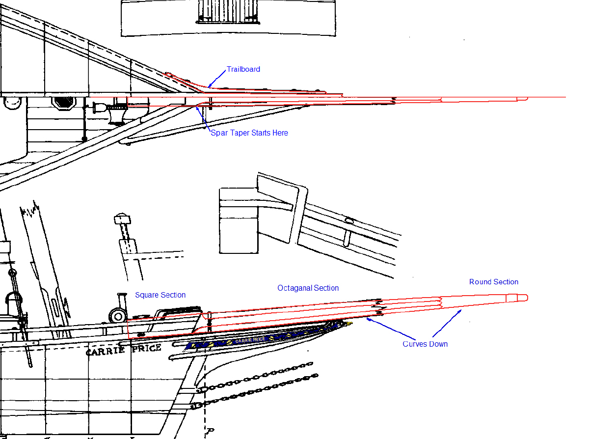
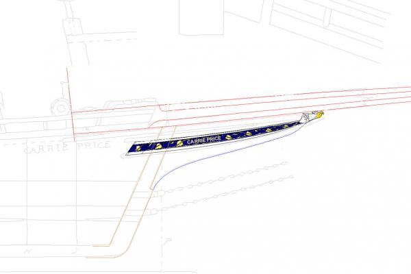
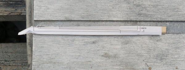
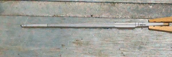
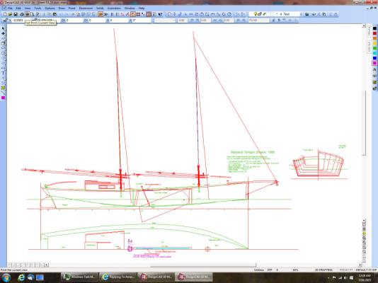
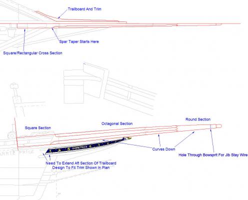
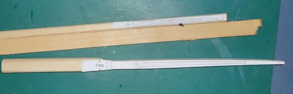
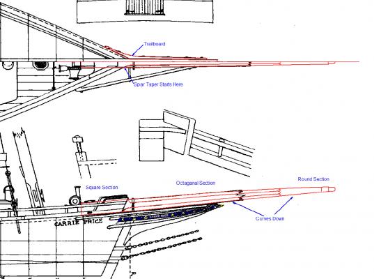
Part 08 Next onto the bowsprit Here is the final drawing of the bowsprit, with the trailboard graphic in place. Note: My CAD program, DesignCAD has an “Auto Trace Bitmap” tool that will trace a scanned drawing, and create a CAD format drawing. This Trace function does not create a finished drawing, the lines are close but not accurate enough for real life. No available trace program does trace accurately enough for a finished drawing. However what I did was change the traced lines to a light gray, and I use them for drawings like this that detail a part or parts of the final drawing. It gives a much better contrast than the black lines on the scans I’m using to hand trace and make the final drawing. If yours has this same feature, or you have a standalone Tracing program, you might want to do something similar on your drawings. To contrast with the gray line drawing, here is one using the scanned drawing as a background. And here is a sample of the best trace I get, as you can see it is not even close enough for a final drawing. The green lines are the generated trace. I decided to make two bowsprits, a large one (2X) for practice, and a scale one. This will detail the initial work on the large one, as I have to start over (details below). I’m starting from dowels for the material, going to square, sanding the octagonal section, then the round. I started out by gluing a piece of rectangular stock to the small blank, to make it easier to handle. Then using a friends large oscillating belt sander I sanded one side of the dowels flat. This sander is Nice! It has the belt running horizontally to the table, and in addtion the belt moves up and down verticaly so that you are not just wearing out/clogging, one section of the belt. Then using this flat side down on the table,as a reference, I sanded either side flat and square to the first side. I left one side round, as I need to sand all four sides on the completed bowsprit, so I’ll sand this side while shaping the piece. I squared the sanding surface to the table uing a 3” machinist square as a guide. Here is where I made my mistake. I decided to sand the top and bottom curved profiles first. After doing this I then found that the piece rocked too much to do the side taper. One smart thing I did was leave the blank overlong on the base side, for a handle. I found another problem while sanding the large blank. The shield on my disk sander extends a little past the disk surface. This interferes with getting into inside corners, like where the square section at the base meets the handle. I used to use the belt portion of the sander for these areas, but at the moment, I don’t have a belt. I’m going to remove the sheild and grind away a portion to solve this problem. Above is a picture of the sanded large blank, along with the smaller blank, still glued to the rectangular stock. The downward curve of the bowsprit is shown in the photo above. I have to make a new large blank, and resand it. I’ll pick up there next time.


-
Working Comfortably on Upper Rigging
thibaultron replied to capnharv2's topic in Masting, rigging and sails
A little pricer than when I got mine 15 years ago $160. Here's a link: http://www.harborfreight.com/500-lb-capacity-hydraulic-table-cart-60730-10041.html Range 8 1/8" to 27 1/2". Overkill, maybe, but at 500# capacity, it should lift anything we build. -
Working Comfortably on Upper Rigging
thibaultron replied to capnharv2's topic in Masting, rigging and sails
This may not work for you, but here is what I did for a large 1/8th scale ride behind locomotive I have. I bought a hydrolic lift table from Harbor Freight, for about $100. I just raised and lowered the table as needed. You could attach a table to it, with legs that go through the table. Have holes in the legs, that you can slip a rod into, to lock the table at various heights. Use the lift table to change heights, and roll it out of the way when working. The handle of the cart would get in the way of working on the model, unless you can modify it somehow, or have it turned to the side.. -
Frank; Thank you for the compliment! I have been working on actual construction of the bowsprit, and will post what I've done soon.