


fnkershner
-
Posts
1,595 -
Joined
-
Last visited
Content Type
Profiles
Forums
Gallery
Events
Posts posted by fnkershner
-
-
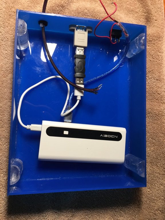
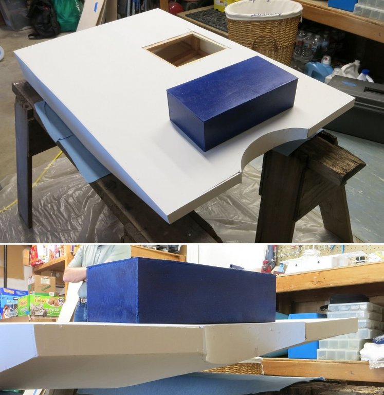
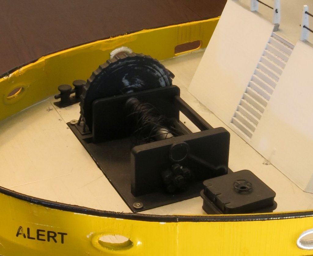
Ok as promised here are some pictures of the control boxes.
The first picture shows the inside of the box. We used an external Cell phone battery. This battery has 3 ports. 1 is a micro port for charging, and the other 2 are standard USB for output. We chose the one with the highest amperage.
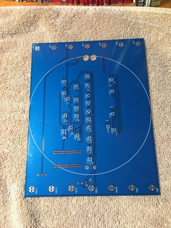
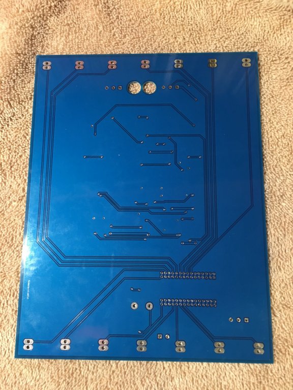
Next you see both the front and back of the PC board.
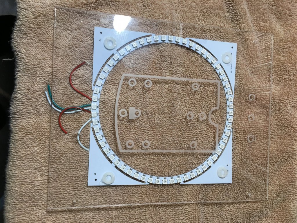
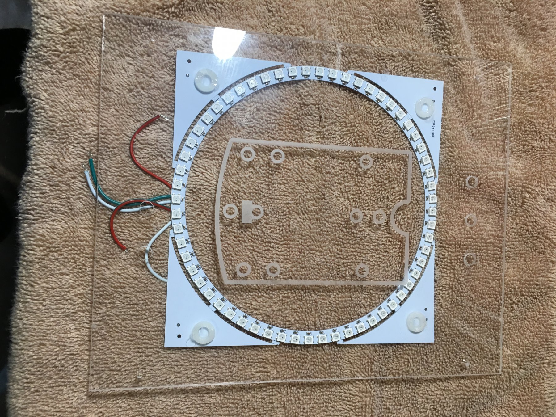
The next is the faceplate for the tug with the Neopixel ring mounted.
- GrandpaPhil and mtaylor
-
 2
2
-
Just a further update. As mentioned above there are 4 major parts to this project they are as follows:
1. Build a model of a Alert Class tug using 3D printing technology. As documented in this log this is completed and delivered to the customer.
2. Build a Model of a fueling Barge. This model was built of wood with 3D printed parts on the deck. This was delivered to the customer last week.
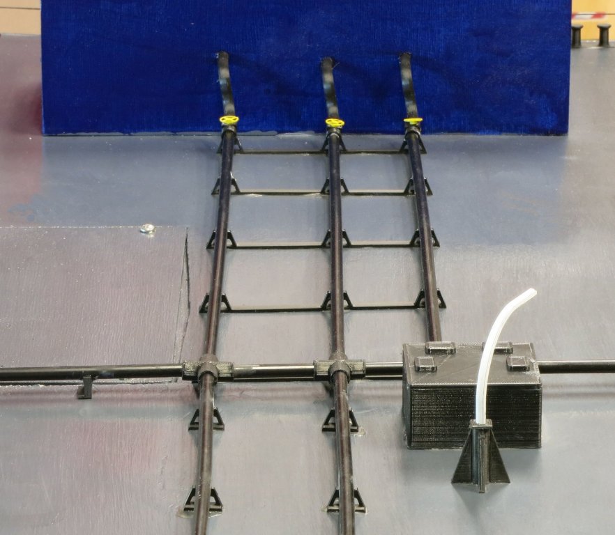
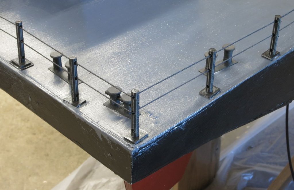
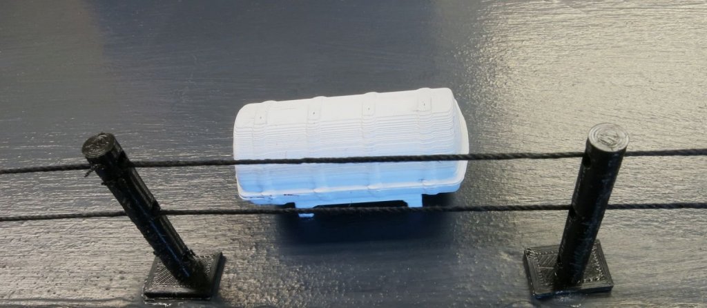
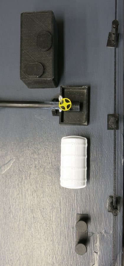
3. Build 1:35 scale oil containment booms. Each would be a scale 100 feet long. 9 of these were created complete with functional Z connectors. these were also delivered last week. I will get pictures to post the next time I go to the school.
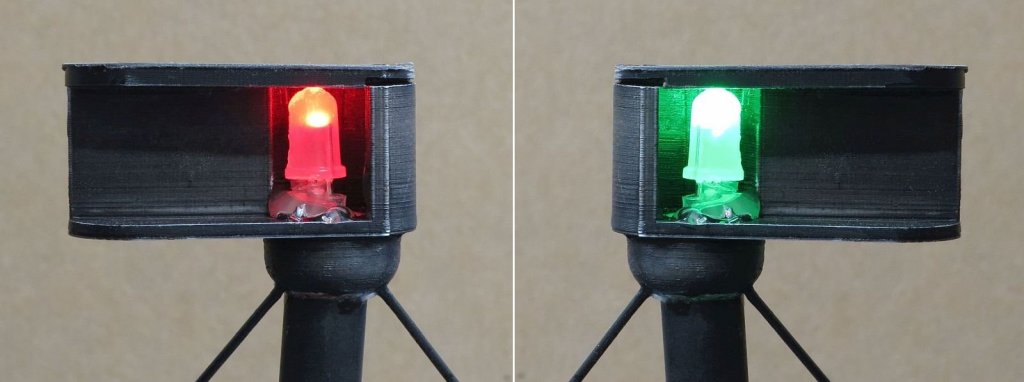
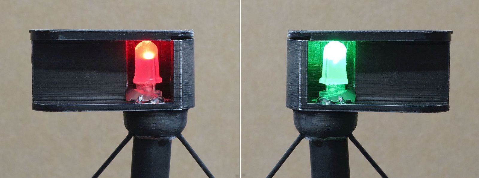
4. Using the Coast Guard regulations light both models with LEDs to represent proper lighting on ocean going vessels. This included building from scratch Control boxes that could be used a teaching tools. These control boxes will have a schematic of the vessel etched into the face plate. There will be indicator LEDs located in the faceplate showing the approximate location of the light in question. There are push button switches for each set of lights. In addition to the indicator Lights there is also a ring of 60 Neopixel lights surrounding the schematic. This ring will indicate the angle of dispersion for each set of lights when the proper button is pushed. For example if the button is selected for the red/green side lights. According to the Colregs, the dispersion angle is 112 1/2 degrees. This means that both the red & green side lights will be visible from dead ahead to a point 22 1/2 degrees adaft of beam. The total angle would be 225 degrees. So on the model the ring will light the appropriate indicator in the correct color and the ring for the proper angle with the proper color for 10 seconds. The reason for the 10 second limit is too allow multiple switches to be depressed. The indicators will stay on as long as the box has power. The on/off will serve as a reset.
To accomplish deliverable #4 here are the steps taken. (completed pictures will follow in a couple days).
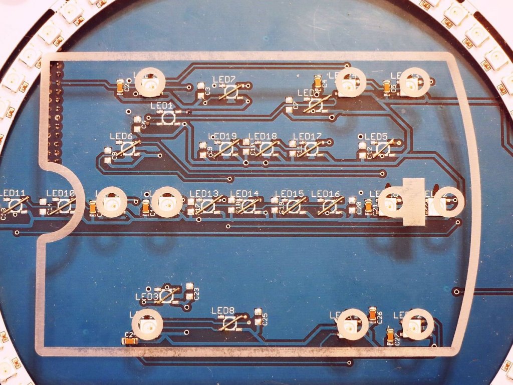
Using a 40 watt CO2 laser we cut the control box and etched the face plate. The total size is 8 X 10 X 2 inches. In one side of the control box 3 holes were cut. One for the on/off switch, one for the signal cable to connect to the model, and lastly one for the battery charging cable. Next we designed a custom PC board that had the circuitry necessary for both models. The barge has 5 switches & 10 lights, the Tug has 14 switches & 19 lights. On the back side of the PC board an Arduino Nano was mounted and programmed. The ring was mounted to the face plate and the PC board was mounted to the faceplate using the switches. What you see below is the Schematic for the PC board. My next post will show the parts and completed box.
- GrandpaPhil and mtaylor
-
2
-
Mark - Who is Frank? 😁 Maybe he is better at LEDs than me.
- Jack12477, thibaultron and mtaylor
-
3
-
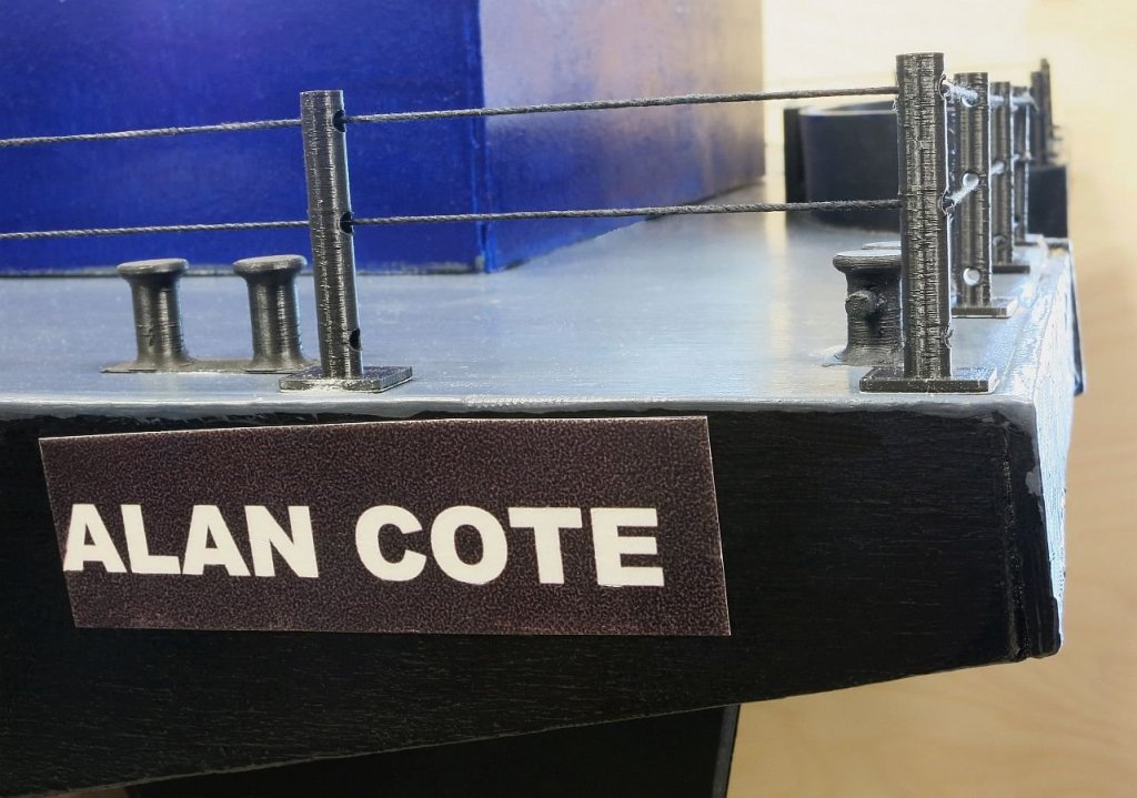
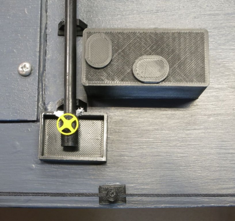
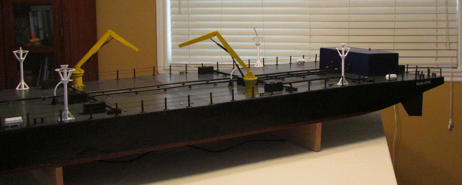
Ok, if you have made it this far in the log then you know the story of christening the Barge with the name of Alan Cote. While Mike was taking pictures I was applying decals. But I had clear decals that did not work on a Black hull. So I tried to use a backing. This is what you see in these pictures. But we found that the backing didn't stick very well. So I started over with opaque white Decals, and this worked. For the eagle eyed you will see that one of the work lights has wires hanging out. This is the 10th LED and I spent all night trying to get it to work. I will have to drive to Astoria to continue my work. Also you see a picture of the control box. This is not working yet. but I expect to resolve the remaining issues tomorrow.
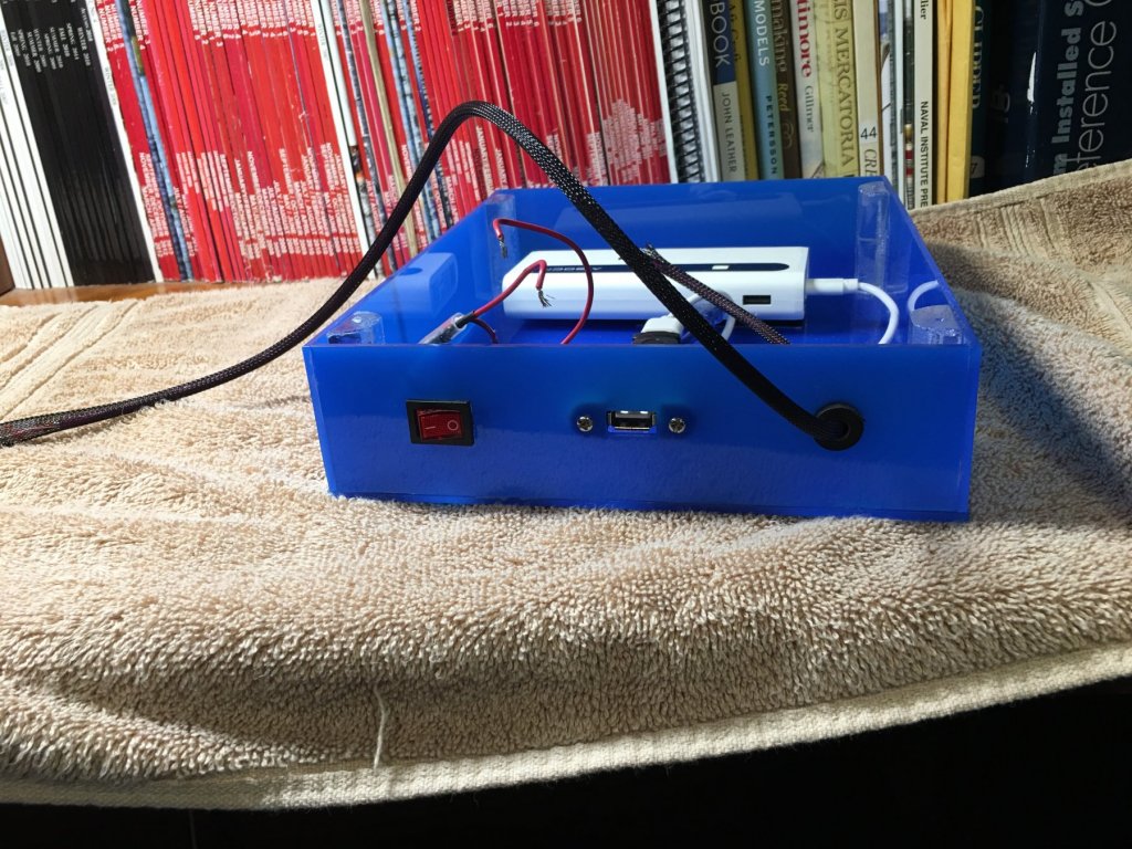
So a bit of an explanation of the control box - The box is 8" X 10". It has a 5 volt cell phone battery inside. It has an on/off switch, charging port, & signal cable to connect to the model. On the face plate you will see a schematic representation of the barge model with indicator lights at the relative position on the model. And finally there is a ring of 60 LED around all of the above. This ring will light up to represent the dispersion angle of the lights. You will also see 5 switches. If the user depresses the switch for the Side lights. The result will be that the red & green light on the model & the control box will light up. Also the portion of the ring that represents to dispersion angle will also light up in the proper color. So you will get red for an angle of 112 1/2 degrees and green the same. There are still some pictures in post processing. I will add them when available.
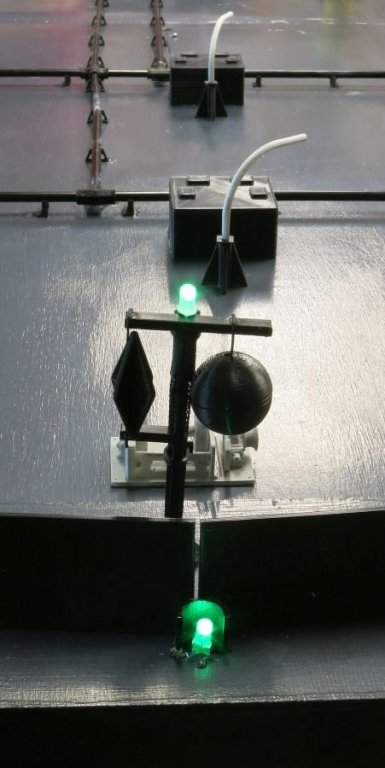
The Lights are a very important part of this project. Since the models will be used in the Seamanship classroom. the instructor expects to turn on a set of lights and ask the student to tell him what he sees. Or he will tell the student a situation and ask him/her to set the appropriate lights. This is part of the final exam and they will not get their Coast Guard Certification if they do not pass. For the barge it was the lights to consumed the most time and effort.

- GrandpaPhil, Nirvana, thibaultron and 3 others
-
6
-
Ok, sit back and enjoy! the barge is done. Well sort of. I will explain. There are so many pictures to share it will take 2 replies. So here goes -


- Jack12477, mtaylor, thibaultron and 2 others
-
5
-
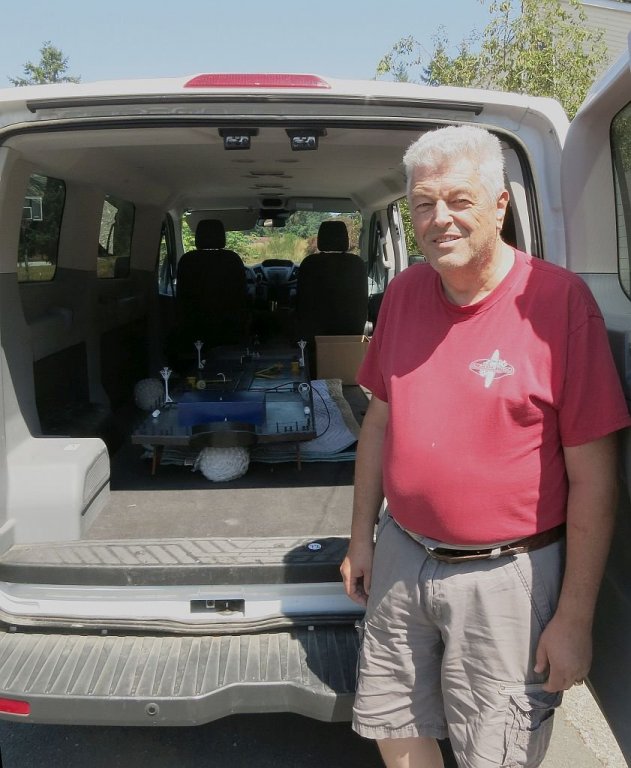
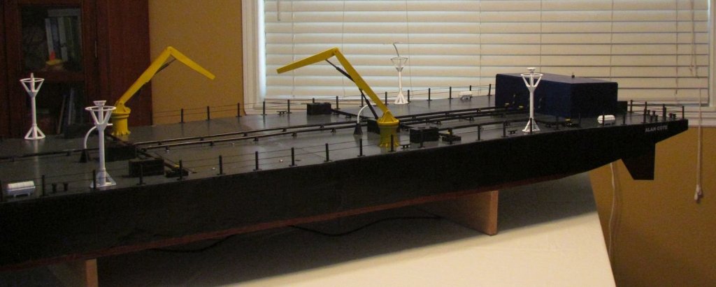
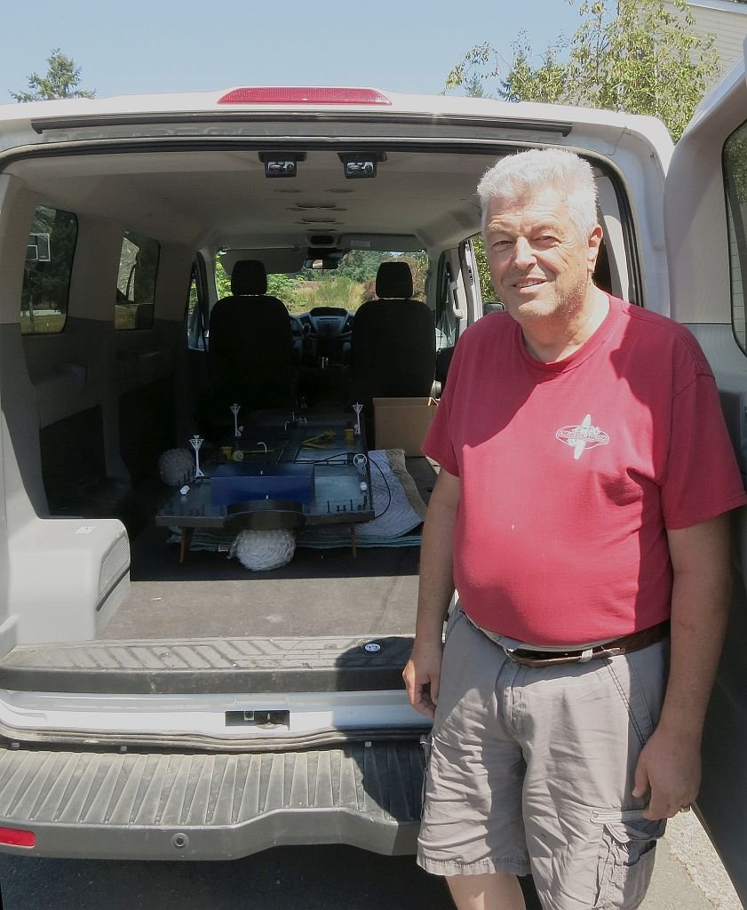
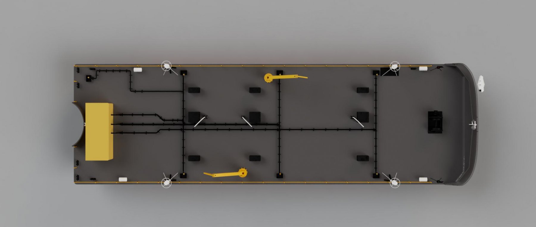
Ok time for an update on the barge. They are bringing a van on Tuesday to take it to Astoria so I better finish all of this.
The first picture is an aerial view rendering. Thanks to Per. The rest are pictures as she stands now. All of the lights on the port, stern, & bow are installed and working. So I glued all the fixtures in place. I still need to fix a loose connection on the Starboard side light.
So tomorrow I will finish the lighting and then install the rest of the deck furniture.


- mtaylor, hexnut, thibaultron and 1 other
-
4
-
Peter - I need to apologize. I did not go to your log before I posted the above. You are way ahead of me, and you have done an excellent job. I will finish ready the rest of your log as soon as I can. This is perfect!
-
So let me try to describe what I have done. Let me emphasize that I have not completed the process. I am still learning.
Step 1. I got the original plans for the America's Cup boat America from the Smithsonian. They consisted of 2 sheets and were already drawn to 1:48 scale.
Step 2. I went to a local blueprint shop and had the plans scanned in to both a PDF & TIFF. I provided them with a thumb drive and they loaded everything there.
Step 3. I uploaded these files to Fusion as a Canvas.
Step 4. I carefully used the Spline tool to create a sketch of the cross section at the keel.
Step 5. I created an offset plane and projected the Bulkheads on this Plane.
Step 6. I created Off Set planes for each bulkhead and projected the correct Bulkhead onto each.
Step 7. Using the Loft tool I connected each of the bulkheads together to create a solid the shape of 1/2 of the hull.
This is as far as I have gone so far. My plan is to mirror the above to get the complete hull. I have also been goofing around with the Slicer tool. It will create for me each of the bulkheads. From my limited experience it looks like it was custom made for a ship modeler. I can specify how many bulkheads I want and it will create them evenly distributed along the length of the model. It will even lay these parts out on a sheet of whatever material I specify. I can then take these plans to either a CNC or Laser and cut them out. I believe that I can get both the bulkhead former and the bulkheads complete with the slots cut into them all from Fusion.
I have also been toying with the idea of cutting a half hull using just the Fusion model & a large scale CNC. I have access to a CNC that has a max of 8" in the Z direction. This should work.
I will try to post a rendering of the work mentioned above in the next week or so.
When I asked above for more details this is kind of what I wanted. I would love to find someone else who is using Fusion to accomplish something similar. It seems to me that Fusion can make it easy to either create a solid hull or the parts for a frame to plank.
-
-
-
I don't know anything about Blender but I really like the lofting function in Fusion. It is very powerful and made just for our purposes. How are you getting the plans loaded into Fusion?
-
As you do this project can you talk it thru a bit. I have a couple catalogs from the Smithsonian. I intend to buy the plans for some interesting ships and scan them into Fusion. And loft them from there. I think my first step will be the Use the CNC to create a Half Hull. But the ultimate goal is to create a full model. Have you used the Slicer add-on for Fusion. And have you tried to output the results to a Laser or CNC?
-
-
Per - Do you see the Syren plans on the wall? We have not forgotten her. Also this makes 1 yr for the Alert project.
- mtaylor and thibaultron
-
2
-
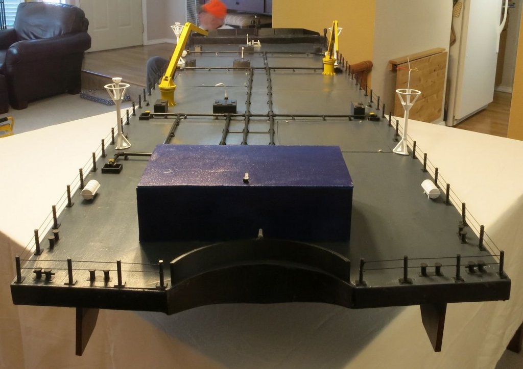
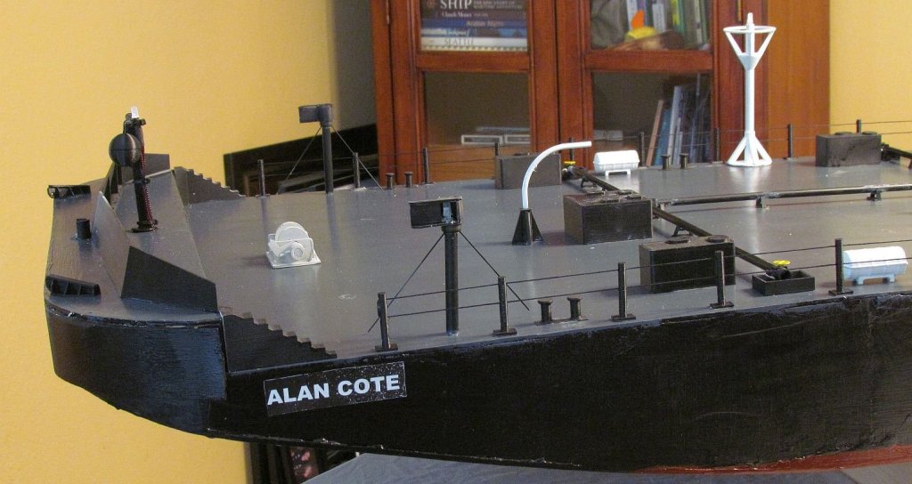
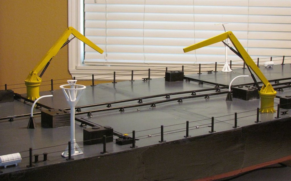
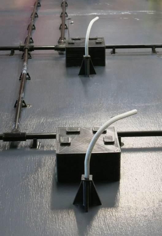
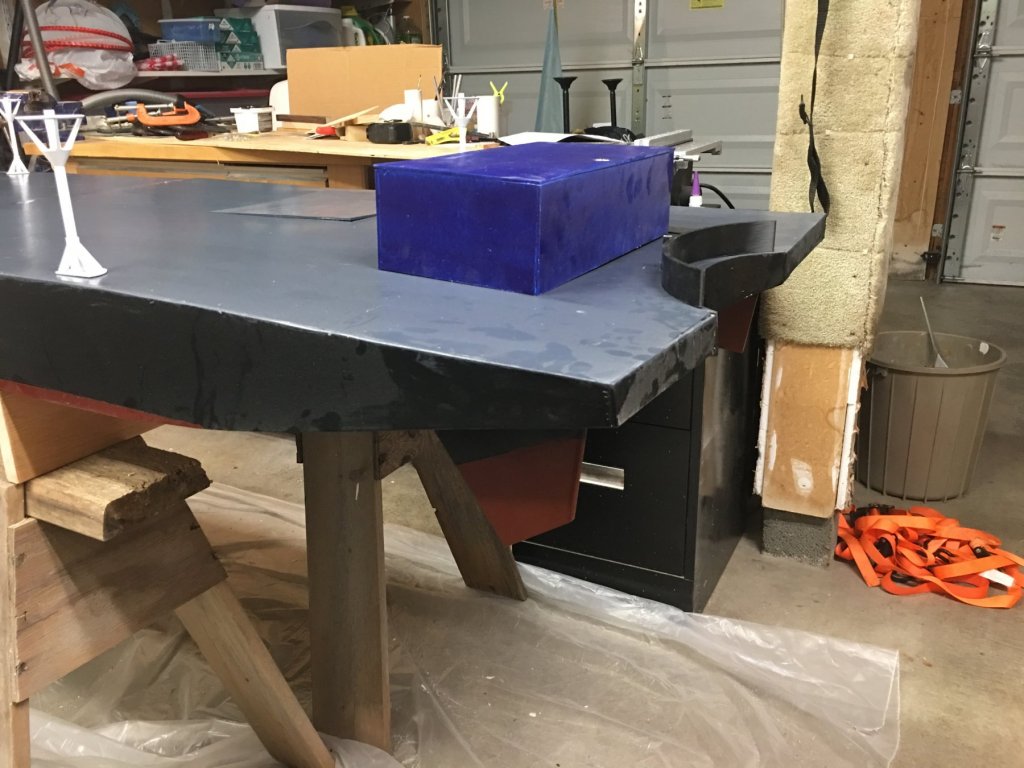
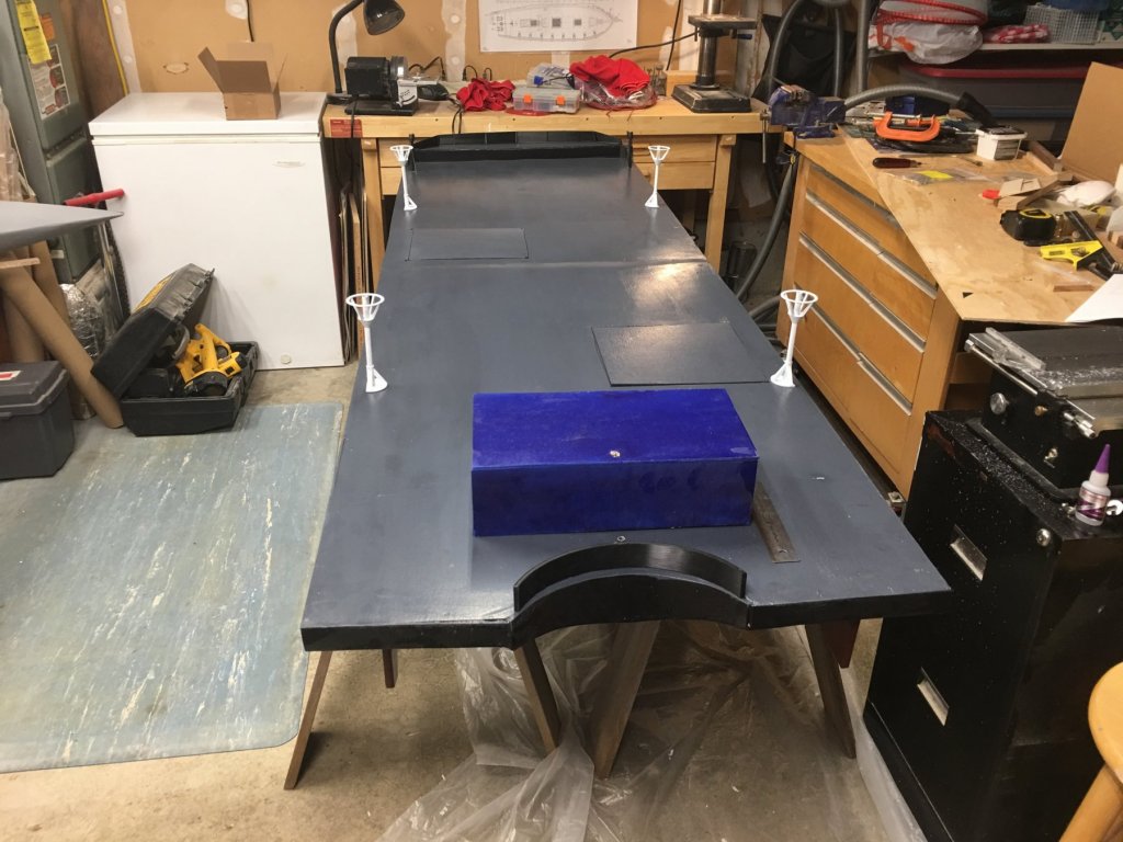
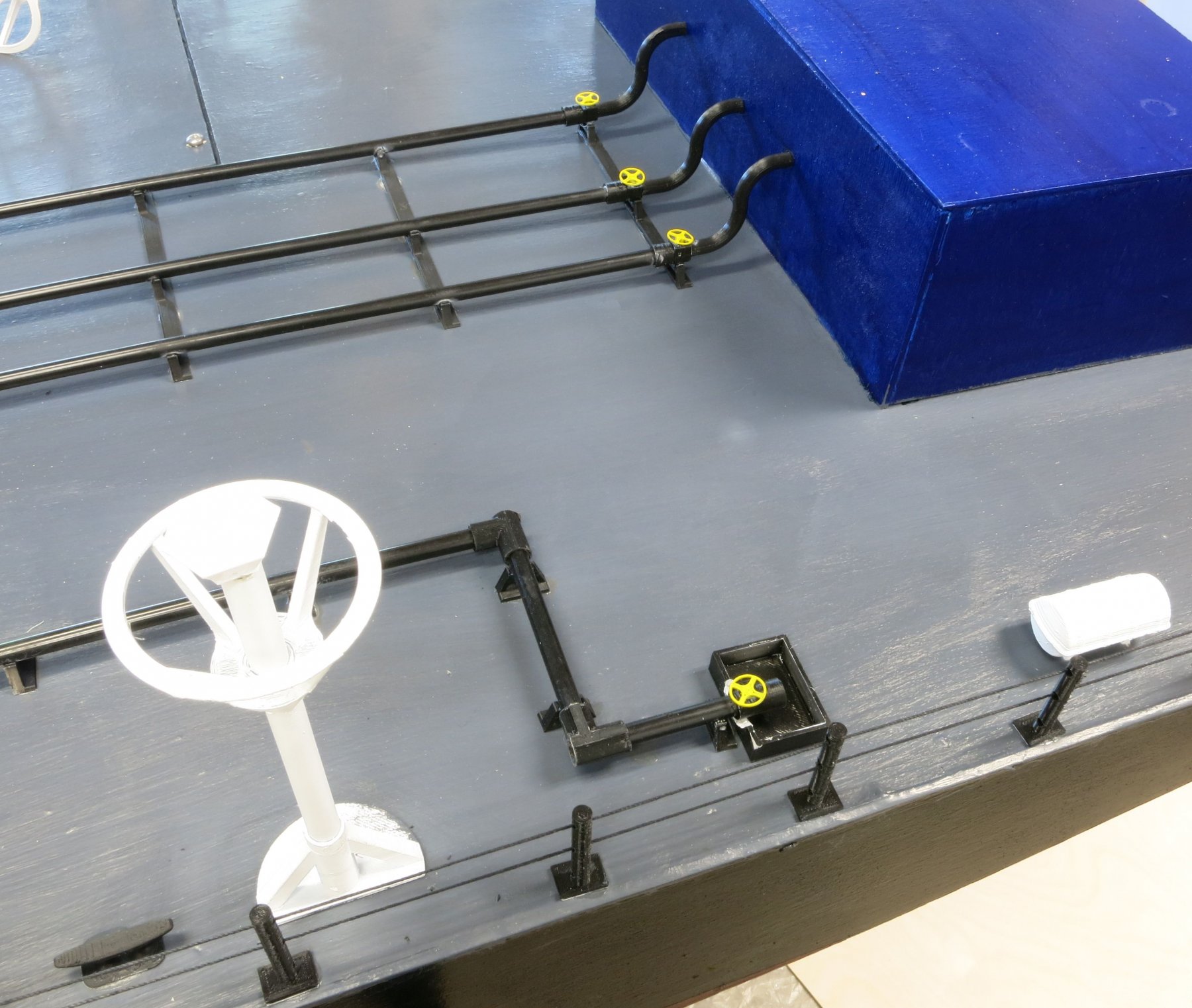
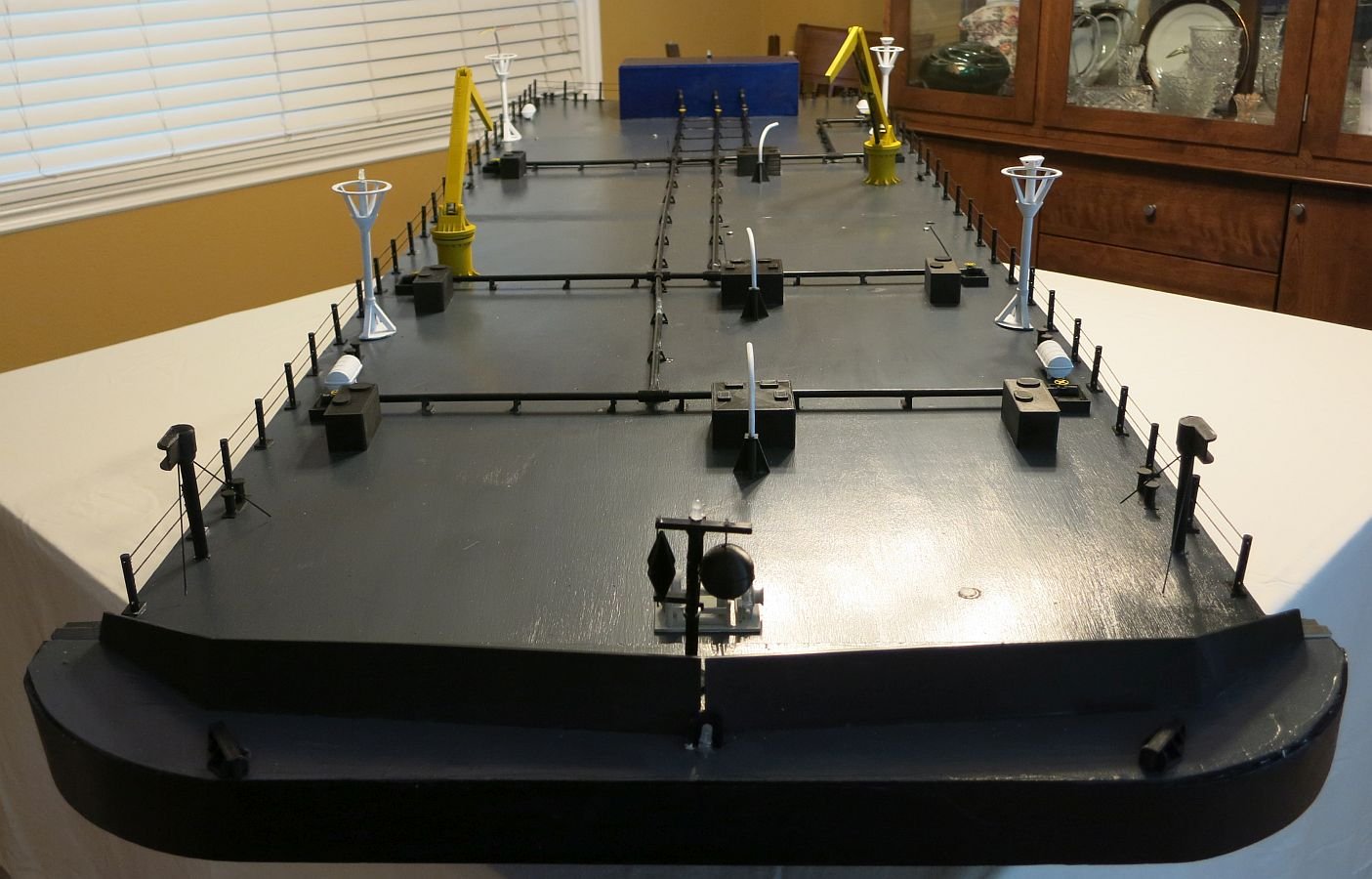
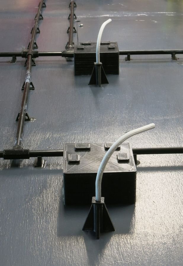
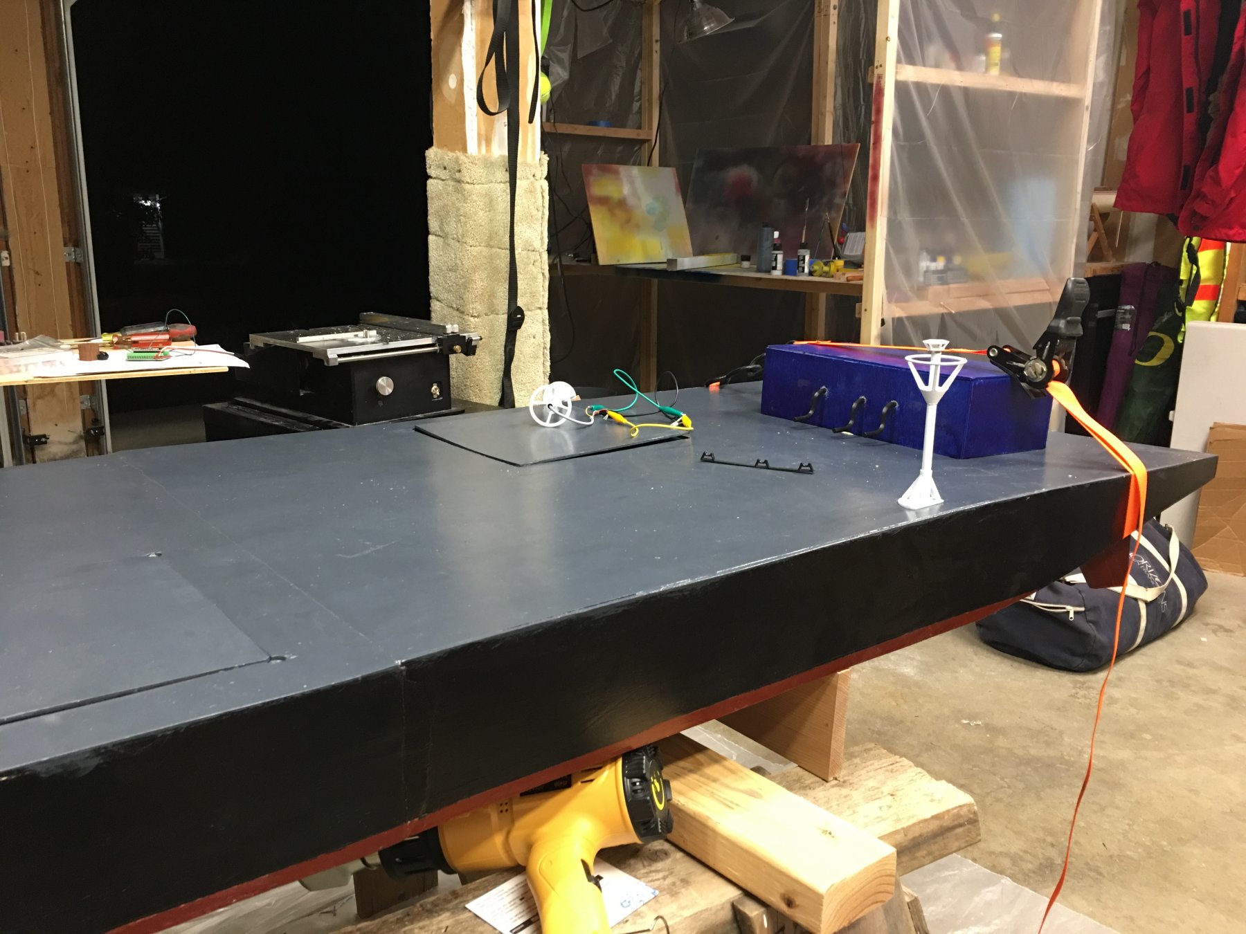
Ok time for yet another update on the barge. Hopefully we are on the home stretch and I can get some sleep. As a retired Professional manager I should know better. But I committed to the customer that this model would be delivered in July. Somehow every project fills the available time. And painting has been slow. You have to paint wait to dry and repeat. What you see in the pictures below is the completed Hull with all the Light fixtures in place. Not all are glued yet, and there are no bulbs. In case anyone asks the big squares are access panels for the wiring. Tomorrow we will complete the Control Panel. I am particularly happy with this. Also in parallel I am working on scale oil containment booms. But we will talk about the control panel and booms after the Barge is wired.
PS I hope from these Pictures you get an idea of the size of this model. It is 7' long and 26" wide.
- hexnut, thibaultron, lmagna and 4 others
-
7
-
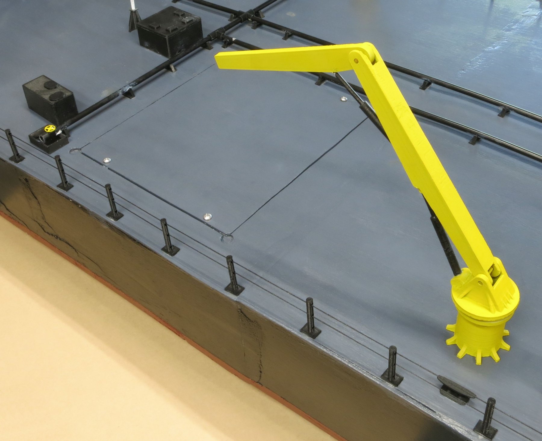
LOL because it is the color I had on hand. I was out of Yellow.
- mtaylor and thibaultron
-
2
-
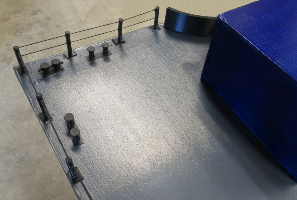
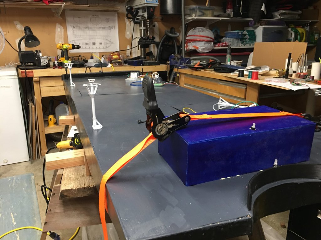
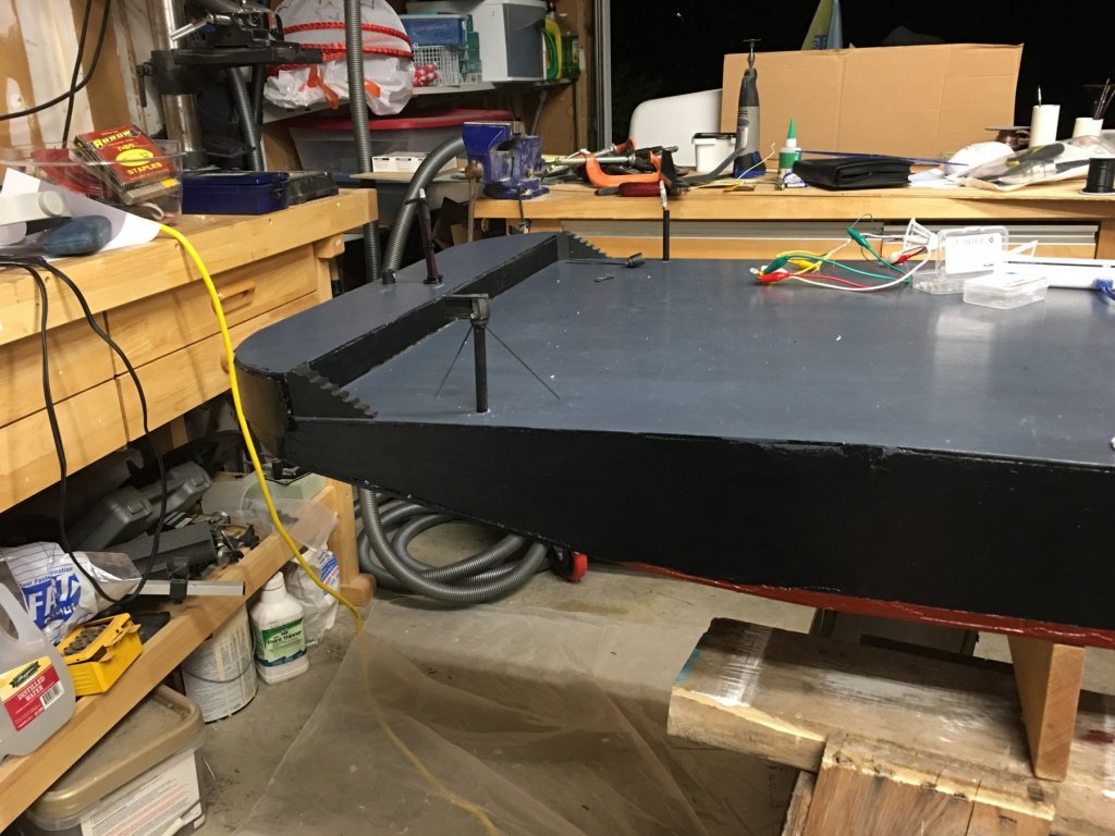
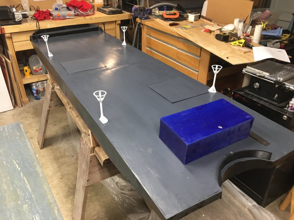
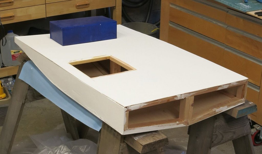
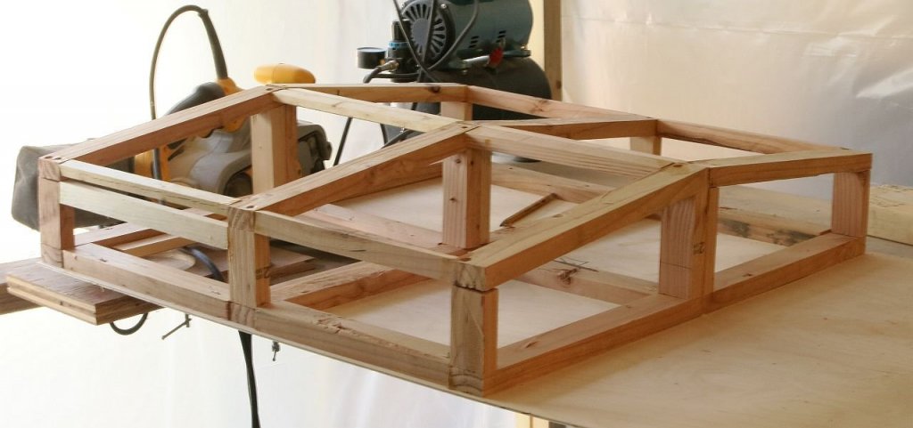
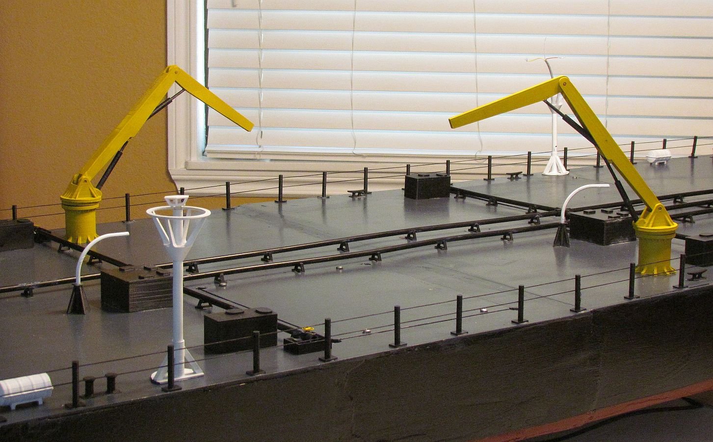
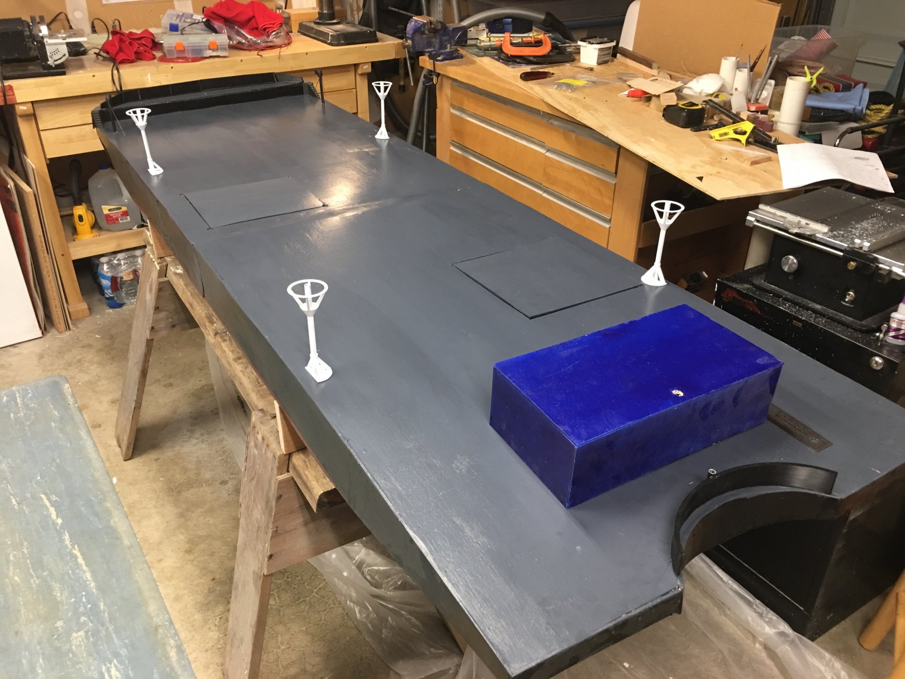
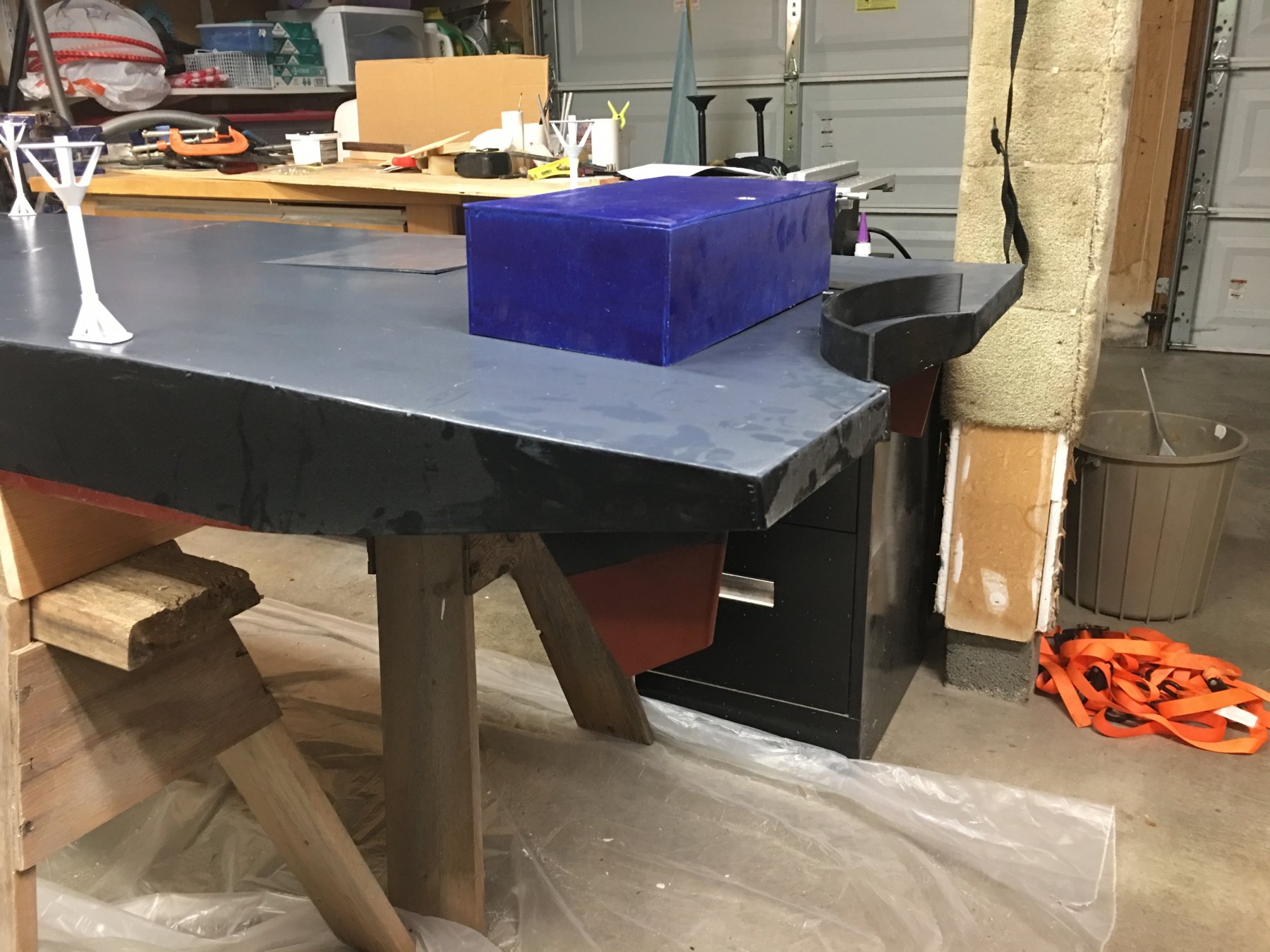
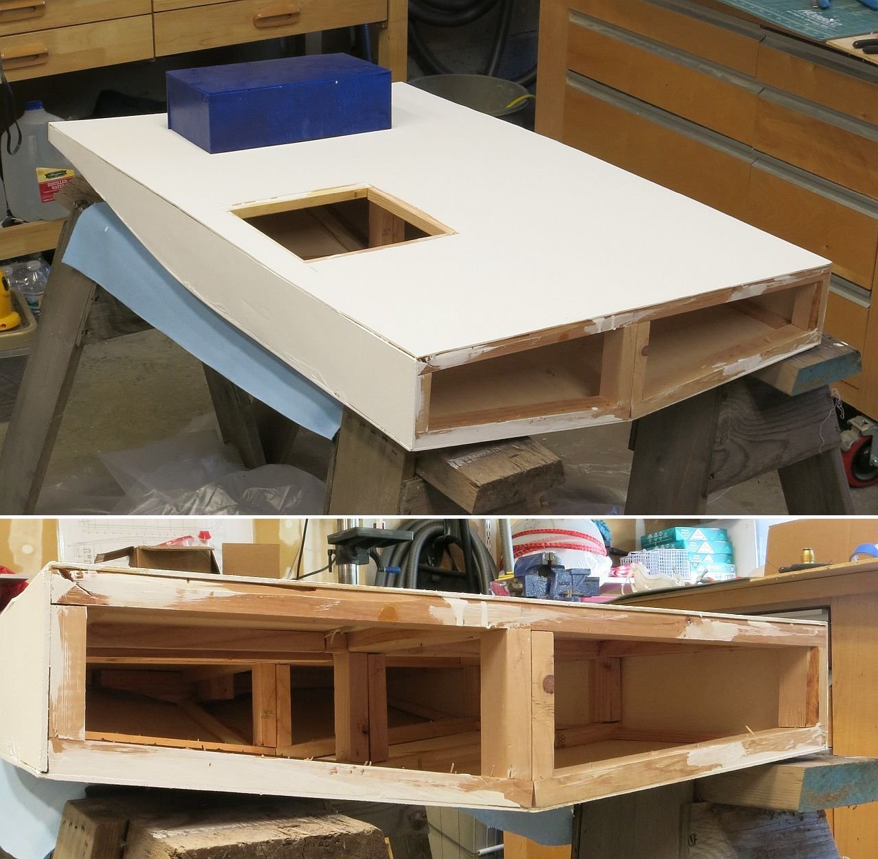
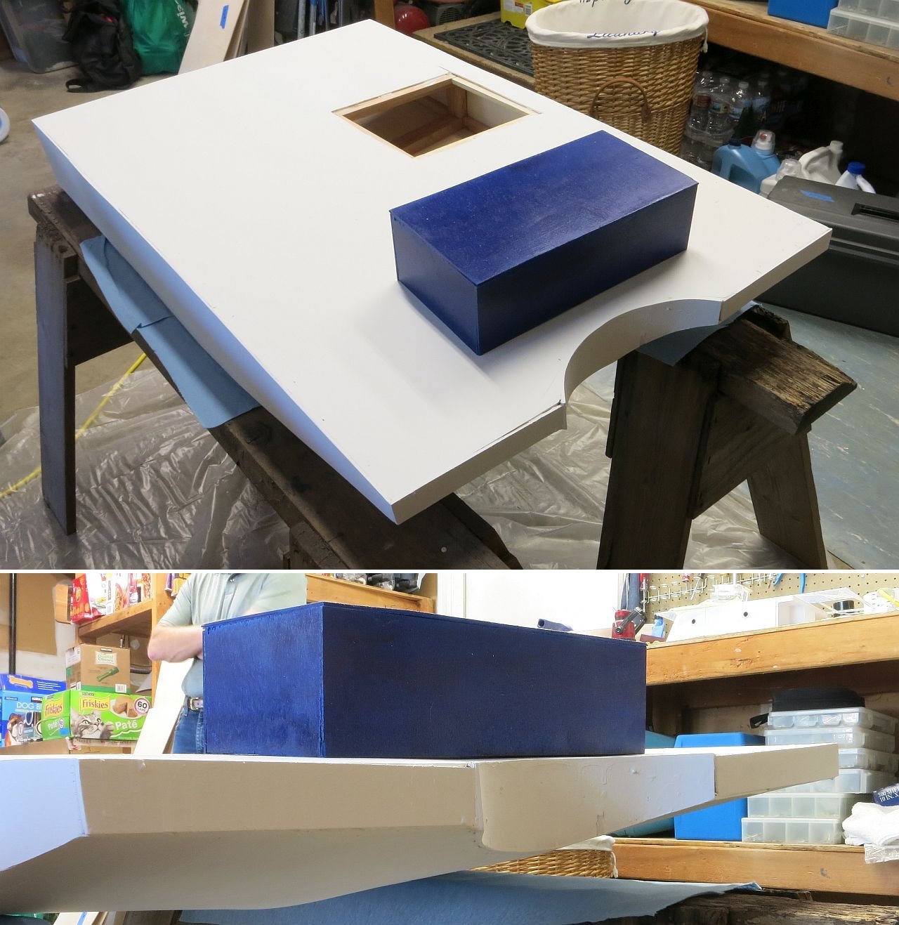
So the next phase of this project is the Fueling Barge. This model will be 2 ft. 2 inches wide, 7 ft. long., and the hull will be 6 inches tall. Since it is so large it is difficult to move around. So I am building in in 2 sections. The pictures you see below are of the finished and primed stern half of the barge. You will also see the model of the pump house which is painted Blue. I also have pictures of the frame of the bow. It is laying upside down on the deck.

- GrandpaPhil, thibaultron, hexnut and 4 others
-
7
-
So here is another update on this project. I expect to finish and deliver everything by the end of this July. So first I want to share with a bit of my trip to Astoria. My wife and I arrived before lunch and delivered the tug model to the Seamanship program at Tongue Point. Everyone was very excited and enjoyed playing with the lights. In fact the next morning I had to recharge the battery they had used the lights so often.
")
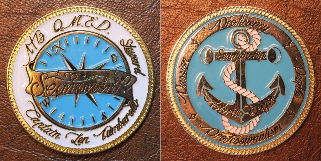
The school is located in what used to be a US Navy Seaplane Base. There is enough barracks to house 600. Currently there are 480 students enrolled in one of the 10 programs offered at this location. As mentioned above my customer was the Seamanship program. I don't know much about the other programs offered here. Anyway I am quite impressed. They have 120 students. They come from all over the US. In 2 years they have earned a High School diploma and either an Able Bodied Seaman certification or a QMED (engineer) cert from the Coast Guard. At Graduation they are presented with membership papers in the Union, the challenge coin pictured below, and the Guarantee of a job paying over $75,000 a year.
The School has a retired Coast Guard Buoy tender to use as part of the training. I was there to ride up the Columbia river to Portland for the Rose Festival. The Buoy Tender is named the Ironwood. I invite you to look her up on the web. she has a long and historic pedigree. During our 10 hour trip I got to meet some of the 55 students acting as crew. It was an great trip.
- thibaultron, hexnut, Jack12477 and 3 others
-
6
-
-
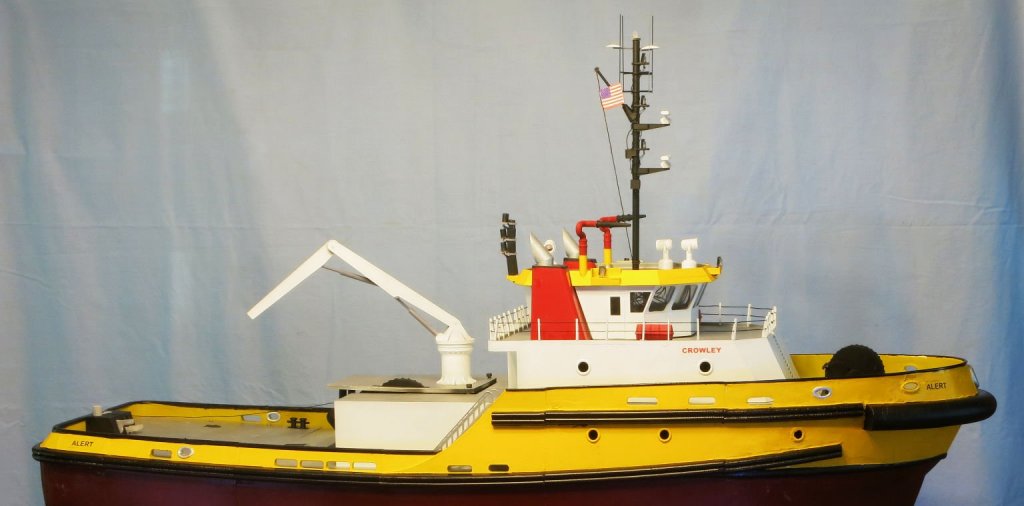
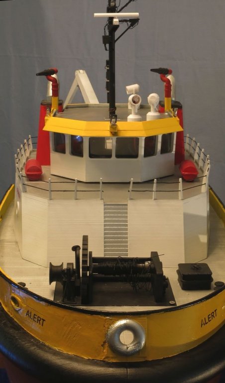
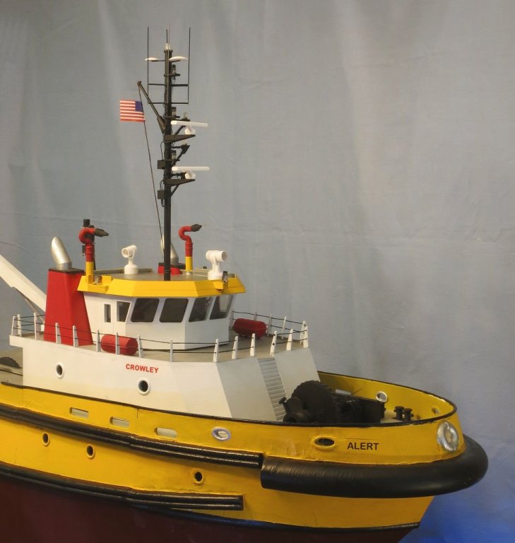
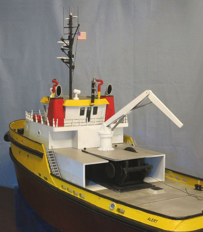
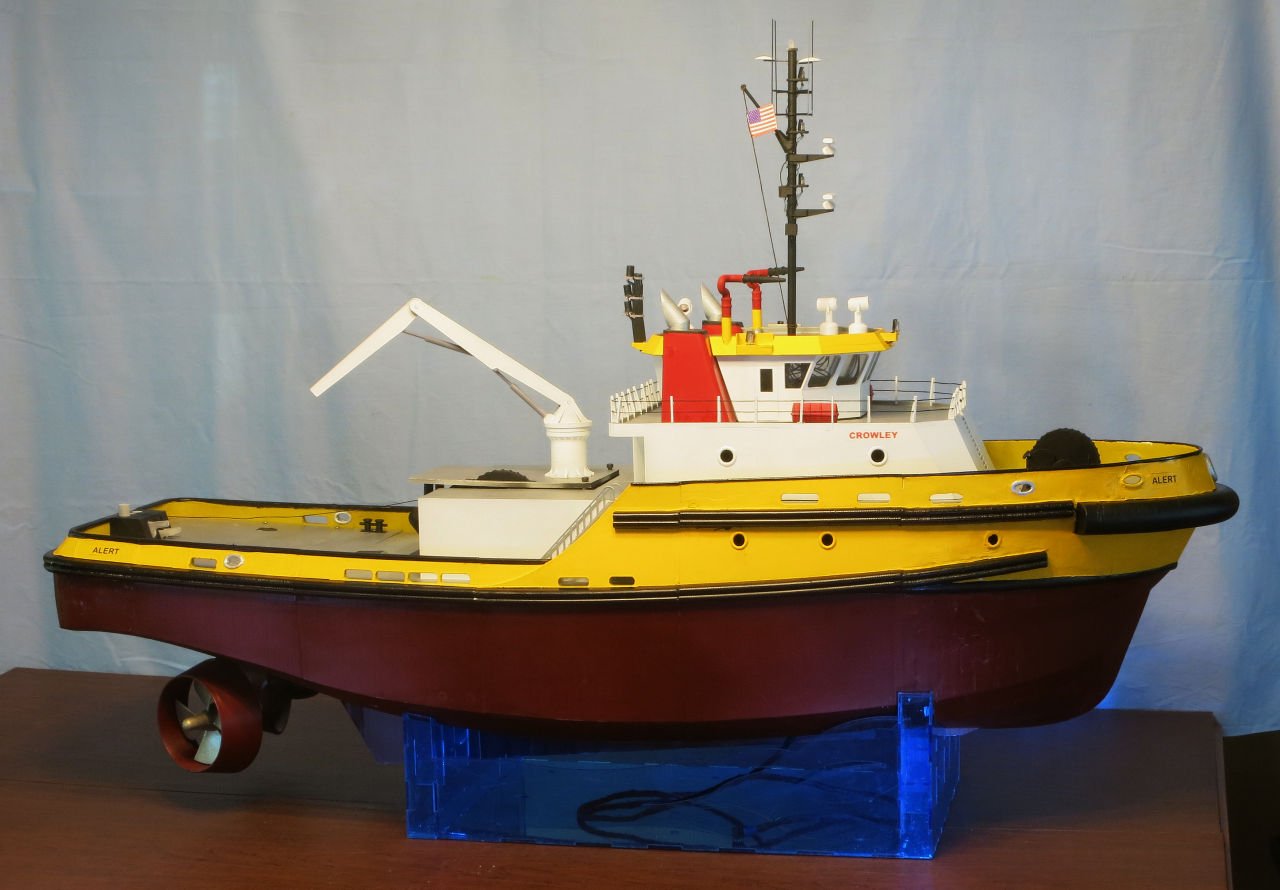
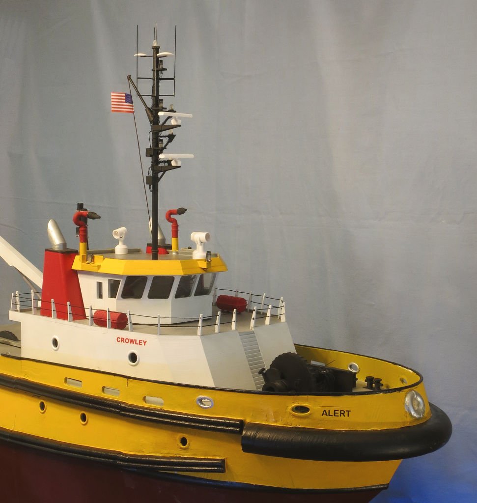
Ok I promised a complete set of pictures before I deliver the tug on Wednesday. so here goes!
By the way Ron thanks for the tip on Word. It worked like a champ. The Tug is completed right down to the decals and all the details on the mast. I must say that Neal did a great job rewiring all the LEDs on the mast using Magnet wire. This was definitely a team effort. After I return On Thursday we will begin to focus on the Barge. The Barge is scheduled to be delivered in July. We will have a christening party in Astoria for both vessels.


- GrandpaPhil, capnharv2, hexnut and 8 others
-
11
-
Anyone know how to reverse text in Word? I need mirror images of the tug name and the company logo to be printed on decal paper.
-
We have a Puget Sound Ship Modeler's meeting on the 25th. I will post pictures of the completed tug then.
- mtaylor, thibaultron and capnharv2
-
3
-
I should mention that Alan Cote was a former president of the union that has worked closely with the Tongue Point School to help all of their students find jobs once the graduate. Alan passed away recently and the school has asked that the barge be dedicated to him. There is going to be a memorial service on the 18th. The rendering presented here by Per will be present at the service. I should mention that for those who graduate and with the help of the Union 98% get high paying jobs. Despite all the issues and challenges, it feels good to be able to help so many find a future in the Maritime industry. I will be visiting the school on the 4th of June and delivering the tug.
- mtaylor, thibaultron, Nirvana and 2 others
-
5
-


Alert-Class Tug by fnkershner - FINISHED - 1:35 scale - 3D printed
in - Build logs for subjects built 1901 - Present Day
Posted
Control boxes continued -
The first picture show the PC board with the switches, indicator LEDs, & capacitors installed.
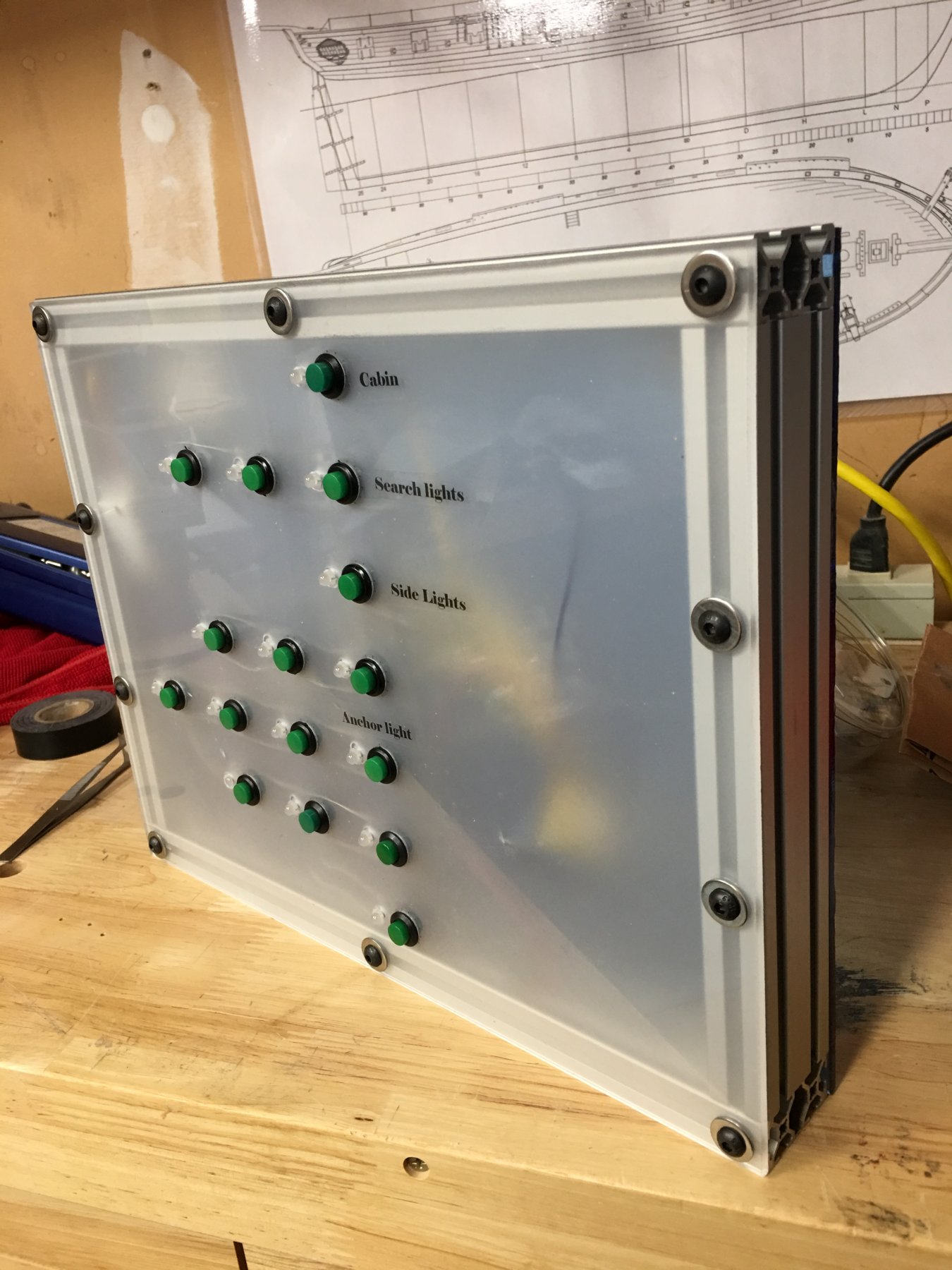
The next picture shows the face plate for the tug.
Since the rings are 6" in diameter we are a bit limited to what we can place inside the ring. The size of the ring also dictated the size of the box and the PC board.
Now I will assemble everything for the barge.