.JPG.ca33079f5815b861e67b9c2cccd37982.JPG)

Blue Ensign
-
Posts
4,265 -
Joined
-
Last visited
Content Type
Profiles
Forums
Gallery
Events
Everything posted by Blue Ensign
-
 Spare Topmasts These were also done earlier in the build as they rest upon the Gallows and Foc'sle rail of the ship. The topmasts are the most complicated masts to make because tapering rounds, square, and octagonal sections are involved. Two spare topmasts are required to fit on the gallows so making these seems a good place to start. I will be using 6mm square stock to make the masts, and then round off and taper for the main length of the mast. Steel’s ratios Main Topmast = 3/5th of lower mast Fore Topmast = 8/9th of Main Topmast Mizen Topmast = 5/7 th of main Topmast Steel’s given dimensions Fore 33’ 4” (158.75mm at scale) Kit plan = 178mm Main 37’ 6” (178.59mm at scale) Kit plan = 192mm Mizen 26’ 9” (127.39mm at scale) Kit plan = 124mm* *Plus pole mast 51mm. Looking at the kit mast plans two things strike my eye immediately. Firstly there is no block below the heeling, and between the heeling and the Lower mast cap the profile of the topmast is shown as square but of a narrower section than either the heeling or the round section above it. The heeling is built up using spare strip to turn the round into a square. In terms of the various ratios of one part of a mast to another the kit dimensions are at variance with the Steel data:- The Block = 1/7th the length of the Lower Masthead The Heeling = Twice the length of the Block. The Hounds = 4/5th the length of the Head. The Head = 1/10th of the Mast Length The first action is to redraw the masts to take into account the shape differences, and then transfer the dimensions to the square stock. A ‘V’ jig is very necessary for mast making. I think it is easier to make topmasts using square stock, rather than try to square off dowel or build it up to represent the square and octagonal sections. The lines are transferred to the square strip and the mast is then formed using scalpel and chisel blades to form the octagon shapes. Fitted in the lathe the round tapering part of the mast is formed. The non round areas are clear of the chuck and protected where the round starts. At this point I introduce my second new toy... I know absolutely nothing about Milling and Milling machines but youtube and a little book with the catchy title of The Milling Machine got me started sufficiently to cut the toprope sheaves in the masts. Cutting the toprope sheaves in the block using a 1mm straight bit. The completed masts in the raw. Sheaves cut for finishing. Head of masts with the hounds shaped. Completed spare Topmasts. I have not made masts to this level of detail before and making the spare topmasts has allowed me to work out the best approach to take. Not sure these two are good enough for the actual masts, but practice makes perfect and eventually I may even replace these spares on the gallows as my skill level hopefully improves. A word on the timber. I am using Lime wood, I like this because it is virtually grain free, carves very easily, and being of a whitish colour allows for a colour finish of choice. The main downside of Lime is that it is fairly soft and can be more difficult to get a sharp edge on say octagonal profiles. I did look at Beech as an alternative; a little harder, a reasonable colour, but too grainy for the scale involved. I don’t like mahogany because of the dark colour which doesn’t appeal and would require painting rather than varnishing to get a paler colour I seek. I will use mahogany for the yards as they are blackened. I quite like and have used Birch dowels previously for lower masts but it is not supplied in sufficient square section sizes to make topmasts. In place on the Gallows Just to see the effect, a boat I made for Pickle but did not use. B.E.
- 363 replies
-
- 3
-

-
- pegasus
- victory models
- (and 2 more)
-
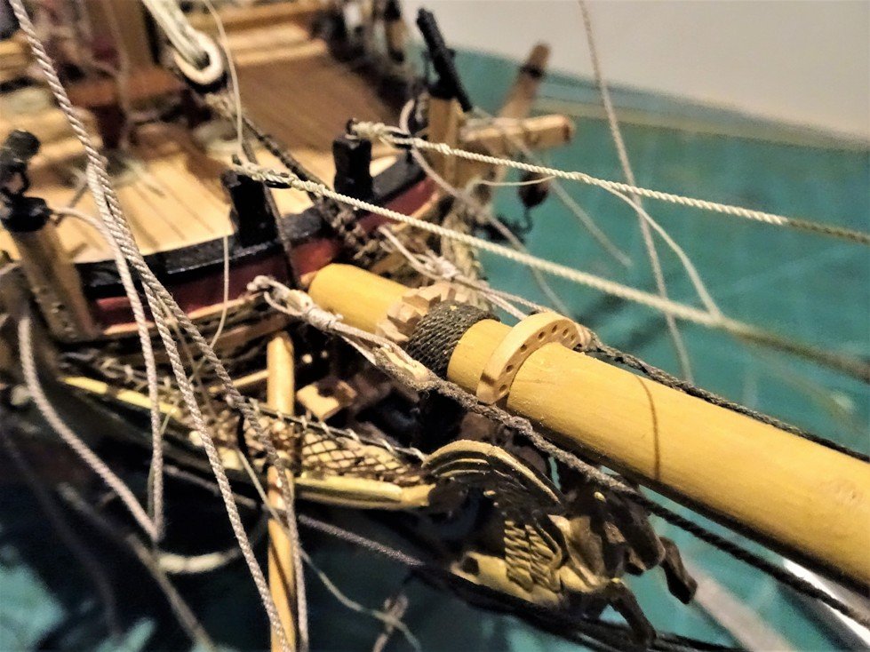
The beginning In preparation for the masting I have invested in a brand new toy. My old Mantua wood turning lathe died on me a while ago, but this proxxon is in a different class, quiet, smooth, and a pleasure to work with. The Bowsprit A good place to start, not least because until the gammoning is fixed I can’t complete the headwork finishing touches. It is also a good exercise to get into mast making. Bowsprit Modifications I have put aside the provided walnut dowel in favour of Lime wood which I can colour to suit myself. Having achieved the basic spar dimensions the bowsprit has to be squared at the outer end, rebates cut to take the Bees, and the tenon for the cap cut. BEES The kit provided Bees are simple Walnut affairs with slots to take the Fore topmast and preventer stays. There is no mention of the Bee blocks that sit beneath the Bees and contain the sheaves for the Fore topmast stays. Steel is quite expansive on the subject of the Bowsprit fittings, and I followed his lead. The Bowsprit Cap I dispensed with the provided cap because the holes for the bowsprit and Jib Boom were central to the cap and made no allowance for the Jack Staff. Bowsprit caps were slightly wider on the starboard side of the mortise for the bowsprit and hole for the Jib boom, to allow for this. I scratched a cap from an old boxwood ruler courtesy once again of Mr Rabone. The main complication for the cap holes is that they have to follow the stive of the bowsprit so the holes have to be angled at the correct degree so that the cap sits vertical to the keel when viewed from the side. Angled inserts were put in the vice to give the correct stive before drilling. The kit instructions rather gloss over this simply saying that the Cap should be 90 degrees to the keel, but as the provided piece has pre drilled vertical holes it would present a problem in then trying to angle the holes without eating excessively into the surrounding woodwork. The scratched cap, bees, jib saddle, and Woolding hoops. I made the hoops from styrene strip for this particular woolding as all will be painted black. This feature does not appear in the kit instructions. The Jackstaff in place now you can see why the cap is wider on the Starboard side. There is no provision in the kit for a Jackstaff. At the other end the Gammoning cleats have to be fitted. To mark their position a temporary line is fed thro’ the slot with the line restrained at the aft end of the slot. The line has to be vertical to the keel. The faces of the cleats are angled to meet the run of the line. Jib Boom I cut this from 4mm Lime wood square stock because the inner end of the boom should be octagonal, the remainder of the boom was then rounded on the lathe and the necking formed at the end. In shaping Octagons it helps to make a little ‘V’ jig to hold the timber section in the right position for planing Two other points not indicated on the kit plans; there should be sheaves set into the boom at the inner and outer ends and a hole at the inner end to facilitate the heel lashing. The Jib boom is blackened from the inner end to the cap and thence varnished. This shot also shows the woolding of the Bowsprit and the lead cover for the spritsail yard slings. With the Jib boom completed the bowsprit is fixed and the gammoning applied. Bowsprit Gammoning 0.6mm dia line is used for the Gammoning; it is important to ensure that enough line is taken to complete the turns and frapping. In the case of my Pegasus I allowed 40” to complete the job. In applying the gammoning to Pegasus there seems to be a difference in the application of the frapping between the Longridge account for Victory and the Antscherl account for rigging a Swan. With Longridge the frapping is taken around the outside of the gammoning and is then seized to itself. With Antscherl the frapping goes around and then crosses between the two verticals of the gammoning before being hitched through the last two turns. Steel makes reference to cross turns of the frapping so this is the method I have adopted. When all the turns are passed, and hove tight, they are frapped together in the middle, by as many cross turns as are passed over the bowsprit, each turn hove tight: the end of the gammoning rope is then whipt, and seized to one of the turns. The frapping increases the tension; and adds to the security acquired by the purchase. The Gammoning is Morope line which has great definition but is a little more time consuming to work with. Rather than buy black line for the standing rigging I prefer to dye it myself using Colron Jacobean dark Oak wood stain which gives a more scale black and over time fades to a dark brown/black, more in keeping with Stockholm Tar. Fitting of the Bowsprit and up to this stage was actually done earlier in the build as it needed to be done before the Headworks were completed (see posts 73-75 in the first part of the build) As I fiddled around the Bowsprit area much later in the build I suddenly realised I had forgotten to fit a Bowsprit saddle, the fairlead that carries some of the rigging lines from the jib. It wasn't too problematical even at that stage to retro fit, but would have been better fitted at this point so I include here as an amendment. A card template to gauge the fit over the Bowsprit and a suitable bit of Boxwood out of the scrap box to make the saddle. The Saddle sits just forward of the Bowsprit Gammoning. B.E.
- 363 replies
-
- 3
-
-
- pegasus
- victory models
- (and 2 more)
-
Index of subjects PEGASUS Masting and Rigging LOG INDEX SUBJECT PAGE Post No. SUBJECT PAGE Post No. Masting and Rigging Index Part Two Four 111 Bowsprit Modifications 112 Fore yard Jeer Tye falls. Seven 204 Spare Topmasts 113 Main Yard completion 205 The Lower Masts 114 The Crossjack Yard 206 Wooldings – 116 The Gaff 207 Bibs 115 Topmast Yards 208 Mizen Topmast 114 Parrels 209 Fore and Main Topmasts Five 121 Main Topmast Yard. Seven 210 Detailing the Lower Mast heads 123 Mizen Topsail Yard Eight 211 Mast Tops 124 Topmast Tyes. 212.214 The Mizen Top dimensions? 125 Main yard clue garnets 216 Scratching a new Mizen Top. 127 Main Course Buntlines Mk11. 217 Re-visiting the Caps. 130 Foreyard clue garnets 218 Topmast Caps and Trestletrees 132 Main Sheets. 219 mast head trucks 133 Yard Tackle Pendants and falls 220 Lower Yards. 134 Yard brace pendants 221 Footrope Stirrups 136. 146. Main Brace Falls 223 Driver Boom or no Driver Boom? 137 Fore and Main T'gallant yards 225 Topsail Yards 138 Main T'gallant Shrouds and stay 226 Studding booms. 140 Lashing the Studding Booms 228 Stunsail boom brackets and rings 140 Bowsprit and Jib rigging 229 Block stropping - 142 Jibboom 230 Fiddle blocks 148 Bowsprit Horses 231 Rigging Attachments for the Bowsprit. 149.151. Jib Stay 233 closed hearts Five 150 Anchor rigging 234 Stays, Collars, and hearts. Six 154 Adorning the Cat head 236 Yard tackle pendants 155 Main Stay - tackles. 237 Topsail sheet block 156 Anchor buoys 238 Rigging the Foreyard 157 The Spritsail Yard Eight 239 Swivel gun mounts for the Tops 158 Mizen Topsail Yard Braces Nine 242 Pendants of Tackles 159 Vangs 242 Stepping Masts Mizen shrouds 161 Main Sheets 243 The Mizen Stay. 162 Main Brace Falls 243 The Main Shrouds 170 Main Tack 243 The Main Stay 172 The Fore Sheets 244 The Fore Shrouds 176 The Fore Tacks 244 Futtock Staves 178 Stanchions,misc items 245 Ratline application Six 180 Swinging Studding Booms 245 Fitting out the mast tops Seven 181 Making Ensigns. 246 Topmast deadeyes and Catharpins 186 Fitting Ensigns 247 Fore and Main Futtock shrouds 187 A base for Pegasus 261 Rigging the Jeers. 192 Thoughts about Pegasus 271 Mast top Rails 193 Completion Photo's Ten 286 Euphroes and Crowsfeet 194 Pegasus Topmast Rigging 196 Topmast Ratlines 199 Mizen Topmast Stay 200 Fitting the Fore Yard 201 Main Topmast stays 202 Main topmast backstays 203

- 363 replies
-
- 1
-
-
- pegasus
- victory models
- (and 2 more)
-
Masting and Rigging of Pegasus. This is my opening post of the reconstructed log covering the Masting and rigging stage of my Pegasus Build. It was originally started on 29th January 2013. Throughout the mast making phase I refer to Steel and make comparisons with the kit dimensions. B.E.
- 363 replies
-
- 1
-
-
- pegasus
- victory models
- (and 2 more)
-
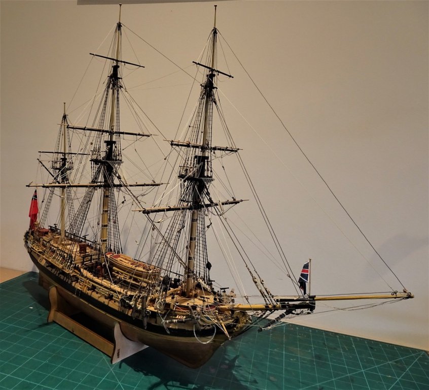
This post brings to completion the hull stage of the build. Pegasus back in her temporary case This is one of the last photo's I took of Pegasus on 22 February 2017. I am currently working on the reconstruction of the Masting and Rigging part of the Log. This will be combined with this part once it is done. As you can see there is a lot of log to be reconstructed. B.E.
- 363 replies
-
- 17
-
-
- pegasus
- victory models
- (and 2 more)
-
So Pegasus is removed from her temporary case to see how the Longboat looks as part of the package. Firstly with the Pinnace: Seems strange to me why the Pinnace would be larger than the Longboat, and 19' for a Longboat is barely larger than a Jolly boat of a few years later. This was the resin boat which has been externally planked with Boxwood. An option for those who don't want to drive themselves mad with a scratch build. With Pegasus At waterline level. One of my options is to display the Longboat at Water level perhaps using clear plastic rod. This shots gives the relative size of Sloop and Longboat. Well that's about it folks for twelve week diversion, twenty-two weeks if I include the Pinnace. B.E.
- 363 replies
-
- 4
-
-
- pegasus
- victory models
- (and 2 more)
-
Chain plates n' stuff A pair of chain plates is required each side for the shrouds. These were fashioned from 0.5mm ø brass wire coupled with 2mm ø deadeyes. The chainplates were formed around a simple jig. Silver solder was used to bind the two sides together. The loop around the deadeye was formed and joined together at the top, and silver soldered, leaving just enough flexibility to squeeze the deadeye in without breaking the bond. They were then chemically blackened and the deadeye inserted. The completed set. Whilst the enlargement photo's show I'm not quite up to the standard of Fabergé, at true size they look ok to my rheumy old eyes. Attaching the chainplates The tricky part of this is getting the holes correctly placed on the hull to take the retaining bolts. Amati fine brass pins are used for the purpose. For drilling the hull is held against the light which shows up the frames into which the pins will be secured. They proved fiddly to fit mainly because there is too little boat and too much hand, but I got there in the end, at the cost of some minor scuffs on the hull and loss of some blackening on the plates. The two remaining bits of iron work are also completed; these are the chainplates for the backstays. Made essentially the same as those for the shrouds but with eyes each end. Now for the masting and rigging. With the sheet tackle in place the angle of the boom looks ok by comparison with photo's of contemporary models. I had initially thought with the 'high' horse the rigged tackle would throw the boom too high. Shroud rigging in progress; these are tightened by degrees using the lanyards, but a constant watch that the mast is not being pulled out of line is required. At this scale snapping the mast is a real possibility so soft hands are a must. I rigged the Forestay before the Backstays to counter any backward pull from the Topping lifts. The deadeye lanyards are equalised and tied off giving stability to the mast. The Bowsprit is fitted and a traveller was made for the Jib sail halyard; simply made from brass wire and silver soldered at the join. A 2mm single block is fitted with a hook to fit on the traveller and carry the halyard. A similar arrangement is applied to the Staysail halyard which attaches to an eyebolt in the bow. The Running Backstays. The pendants are 0.25mm line with hooked 2.5mm blocks attached. 0.15mm line is used for the tackles. Securing the block in the backstay pendant; tense part of the rigging this, the slightest knock of the third hand could break the mast. The Flag halyards 0.1mm line is used, passed thro' the sheaves in the masthead truck and secured to the shroud deadeyes. The rigging is complete apart from some coils to make. At this point I introduce my new Cox'n George. It was necessary to make a scale figure to help me decide about the 'high' horse. in my next post we'll see how it looks together with Pegasus and the Pinnace.
- 363 replies
-
- 3
-
-
- pegasus
- victory models
- (and 2 more)
-
Masting of the Longboat and fiddling with the sticks. Purpose of the exercise to check that the Mast, Bowsprit, Boom and Gaff all look proportional to each other, so a test fitting is called for. The base material for the spars is 2mm ø dowel. Proportions look ok to my eye at least. Think the top of the mast could still bear a little more fining down. The Boom is 72mm long, thinned down a little with a slight taper each end. At the inner end there is a gooseneck fitting to attach to the mast. The iron bands are represented by card. The Gaff is 45mm long with jaws on the inner end. These were formed by slotting the end of the gaff into a bit of 4 x 1.5mm lime strip and shaping the jaws once the glue had set. An eyebolt is fitted atop the gaff jaws for the Throat halyard. Horse This is the iron bar along which the sheet block runs. On the MS kit version circa 1750, the bar is fitted below the tiller, which created problems in allowing the sheet block a free run. Can’t actually find any photos/drawings of contemporary models showing the raised horse, and I’m not sure that it translates well to 1:64 scale. I think I prefer the lower version - I’ll muse over this for a while..... Parrel Trucks Tried using blobs of pva to represent the parrel trucks but given the very small scale I couldn’t get sufficient definition within the available line space of 4mm. I finally settled on using slivers of 0.6mm ø micro brass tubing. Still barely noticeable with the naked eye but they are there and are about as close as I can get at this scale. Mastbands At the masthead should be two iron straps that hold the blocks for the boom topping lift and the gaff peak halyard. The mast head is very fine with sheave holes cut thro’ it which makes it risky to attempt fixing even the finest metal band around it lest the mast breaks during the process. I took the soft option of using 0.7mm etched eyelets to take the blocks with simulated bands of card. A pair of 3/32nd single blocks are attached. The little boat is coming together now. Completed the internal fittings. Belay pins, Thole pins and Thwart knees. Blobs of pva made the Belay pin heads, and the Thole pins are the stems off eyebolts painted. Needs another coat to thicken them up slightly. to be cont'd.......
- 363 replies
-
- 3
-
-
- pegasus
- victory models
- (and 2 more)
-
Sorting out the Rudder. At this scale attaching the gudgeons, pintles and straps to the Long boat are quite fiddly. Starting with the gudgeons on the hull. A small eyebolt represents the gudgeon and a thin black cardboard strip the iron straps. The Pintles on the rudder are formed from a stem off an eyebolt. With the lower gudgeon in place the position of the eyebolt which secured the upper pintle of the rudder can be marked. Having established the position the hole is drilled and the eyebolt checked for fit. I like to cut a narrow horizontal groove across the hole line which allows the eyebolt to sit deeper into the stern post and thereby reduce the gap between rudder and post. The cardboard straps are firstly glued across the groove and taken around the sides to form the straps. The eyebolt is then inserted and the job’s done. At this scale black cardboard is much easier to fit than brass fret, and even looks better in my view. The Pintles on the rudder are formed from a stem off an eyebolt. With the lower gudgeon in place the position of the eyebolt which secured the upper pintle of the rudder can be marked. With the rudder hung the length of the head can be adjusted, shaped, and the tiller fitted. A satisfactory fit close to the sternpost has been achieved. The tiller was made from a length of 0.7mm boxwood square stock. The final part is adding the straps to the rudder pintles. Tiny spots of pva on a needle point are added to the straps to represent the bolt heads. Footnote. Lavery (Arming and Fitting) indicates a different approach to hanging the rudder to that suggested by the MS kit. The rudder was hung on the sternpost by only two gudgeons and pintles. Unlike the rudder on a ship it was likely to be hung and unhung every time the boat was used and it needed to be easily removeable. The lower pintle was fitted to the sternpost rather than the rudder. It was very long and extended almost up to the waterline. The upper one was shorter and fitted to the rudder. This makes quite a lot of sense if you imagine trying to ship a rudder in a pitching boat with the gudgeon below the waterline. Having a long pintle at the lower end would make for easier and quicker location of the rudder. Looking through some of the drawings in the AotS Books – The Frigate Diana, Endeavour, show the ships boats with long pintles on the sternpost . To illustrate the point here's a shot of The Barge onboard Victory. The extra long pintle fixed to the sternpost can be clearly seen. I don’t intend to change the arrangement on my Longboat but I’m slightly miffed because I do now recall from the recesses of my mind that I was aware of this. Had I remembered in time I would have followed that arrangement. Hey ho........
- 363 replies
-
- 4
-
-
- pegasus
- victory models
- (and 2 more)
-
Once more unto the breach... well that’s how it’s felt trying to make the side benches for the longboat. The requirement is they are curved and require notches cut out to fit around the frames. The problem is that just when one is finished the bally edge breaks off.... Still eventually managed to get two intact benches. The final item for this sequence is the lid to the storage box. At this point the mast thwart and the one aft have been glued into place. This is a good time to fix the lifting rings, which are awkward little sods to fix because of the necessarily short stub, and once the thwarts are in place the job becomes more difficult. The knee at the head is added along with the windlass and remaining thwarts. Still some knees to add and some more ironwork. So Gromit what do you think of it so far, what’s that you say on the whole you prefer a bit of Wensleydale, I dunno...... Pressing on.... Nearly forgot to add the moulding strip below the sheer plank; in hindsight it would have been better done before I added the internal fittings – more scope for clamping, and far less scope for inflicting damage. Had a near miss with one of the stern benches yielding to the pressure of a clamp. For the moulding I have used a 0.8mm boxwood strip, attached with ca to give a more instant bond. This was then sanded down a touch and slightly rounded. All ready now for a final cleaning up of the hull exterior. Time to move onto the rudder The usual round has been applied to the inner face of the rudder and taper to the aft face, Still wip at present. Meanwhile I turn my attention to the Bowsprit and its fittings. The Bowsprit is 59mm long, and I used a length of 2mm ø dowel tapered on the lathe. The interesting part is the iron fittings that hold it in place. These comprise two rings, one with a long leg which takes the heel, and one with a short leg attached to the stem. Fortunately I was able to adapt a couple of Jotika 0.9mm brass etched eyelets for the purpose. These were bored out to fit the bowsprit ø The rear support bracket fits thro’ the fore deck and sits against the forward thwart. The leg has yet to be shortened on the forward ring which should be pinned to the face of the stem. Not sure whether there is sufficient woodwork to take a pin so I may just ca it to the stem. to be cont'd.......
- 363 replies
-
- 4
-
-
- pegasus
- victory models
- (and 2 more)
-
First of the internal fittings is the footwalings. Followed by the aft platform and the smaller fore platform. The platform planks are glued to the card template to give a little stability and slot into place. Next up are the risers which support the thwarts. The position of these is quite critical but having used black strip for the sheer strake the line is easy to follow. The risers did need shaping downwards laterally towards the bow . This was done using the wet, shape, and rapid heat dry method. With one fixed the second is glued on and the thwart levels checked before the pva goes off. As this is a reduced scale copy of the MS kit a little jiggery pokery is required to adjust the thwarts positions. The MS longboat represents a 26’ boat having 8 thwarts plus the windlass and stern benches. My boat represents a 19’ boat so a reduced number and some repositioning of the thwarts is required. The windlass is still positioned midships, so the thwart positions will be taken from this point. Nothing fixed at this stage, and won’t be until the windlass is in position. Making the windlass is the next job, might prove a tricky little beggar to make at only 22mm long. The Windlass This was made from a bit of 3mm square section boxwood. At only 22mm long the windlass was formed within a longer length so it could be supported in the jig for cutting the eight sided central section. A further fine sanding and it should pass muster. Working out the mast dimensions The mast fits thro’ a modified thwart so at this stage I need to calculate the size. For this I refer to Steel. For those who may be interested this is the calculation. A longboats mast is three times the breadth of the boat in length, and the ø is 7/10” per yard of length. My boat is 30.86mm wide = to 6.5ft x 3 = 19.5ft length of mast. 19.5ft at scale is 19.5 x 12(”) x 25.4(mm) =5943.6(mm) ÷ 64 = 92.86mm. in length. The diameter calc: 19.5 ÷ 3 = 6.5yds x 7/10 = 4.55” x 25.4 =115.57(mm)÷ 64 = 1.80mm ø at scale. With the size worked out I can make the modified thwart . I first make the mast support hole within the thwart easier to establish the foot position of the mast. This will be further modified now the mast position is established by re-shaping to allow for an iron cap square to retain the mast in place. Mast looks about the right length and diameter but will need a degree of taper. I am using 2mm diameter dowel. The mast support thwart is now modified to fit the iron work and support cap square Firstly the iron work is made. At this scale the brass fret surrounding the etched fitting sets comes in very useful. The assembly in place. So a little further fettling of the thwarts n’ all and they can be glued into place. to be cont'd
- 363 replies
-
- 4
-
-
- pegasus
- victory models
- (and 2 more)
-
With the frames secured I add two bow filler pieces and the transom which I also secure temporarily with a holding strip. Seemed to be a little out on one or two of the frames on the port side for a fair run which necessitated adding strips to the outside frame face before fairing could commence. With the hull inverted the forward and aft frames are very carefully faired with the softest of pressure applied to the sanding stick. The first planks on the hull are the sheer line planks. For these I have used ‘ebony’ strip (dyed boxwood I suspect) of 3.4mm width. There is a degree of sheer on the top strake which requires bending both laterally and with a curve to fit the bow. Using the plan as a guide the strip is first bent laterally by means of wetting, clamping in position, and applying immediate heat to fix the line. One of the additional benefits of attaching a block to the frame tops is that it provides an anchor for clamping the planking strips in place without putting too much strain on the frames which at this point are still quite fragile. The first strakes are attached, the frame tops will eventually be cut to follow the sheer line. I was hoping to get away without having to spile, but it was not to be. At least the spile planks are in the right position below the curve of the hull. With the frames sanded down I can at last get to fit the capping rails, until they are in place I am under constant threat of breaking the top edges which would be a difficult repair. These are cut out on the scroll saw, left slightly over large, glued on and carefully sanded back to their proper dimensions. Two slight mods are now required, one at the sharp end, one at the blunt end. At the stern the height of the transom needs raising above the capping rails by about 2mm so an additional piece was fashioned. Here shown in place but before final shaping. At the bow I seem to have got the stem insufficiently raised above the rails which would present problems both for the rigging attachments and fitting the jib. Again an extension piece was fitted to redress the error. Shown here again before final shaping For these items I used Aliphatic resin glue which is stronger than the usual pva I use. Once the glue has fully hardened I can continue with the cleaning up before I move onto the internal fittings. A quick check with my shipyard apprentice So Wills whaddya think, will it pass muster... Oh dear, doesn’t look too convinced does he. Still we press on...
- 363 replies
-
- 4
-
-
- pegasus
- victory models
- (and 2 more)
-
A 19 foot Longboat for Pegasus The Longboat won't actually fit on Pegasus, but if successful will be shown along side her within the case. I intend this one to be masted and fully rigged. I am again using the larger MS Longboat kit plans, reduced in size to 1:64 scale. To achieve this I use the simple expediency of reducing the print size of the plan originally at 1:48 scale until the keel length measures the required 91mm. Re-using the Pinnace build board I re-marked the station lines to suit the Longboat. First job is to cut out the frame and combined keel/ false keel patterns and pva them to the 1.5mm thick boxwood sheet. This time round I am going to try to cut a fine rabbet along the keel/ false keel line before I cut it out hoping it will give me more control. The pattern has been applied to both sides of the sheet. With the frames I hope to get closer to the finished dimension on the scroll saw and save myself some sanding down once the frames are in place. I wasn’t quite satisfied with my first cutting of the keel using the kit plan. Unlike the Pinnace drawings the notches or rather the depth of the notches for the frames was not shown on the plan introducing an element of guesswork into the equation. So Keel one is scrapped. It struck me that why not scan the actual kit keel which of course has the notches pre cut and then reduce the scale to 1:64. Because of the small scale I have not separated the keel from the false keel. The stem piece was cut out, glued in position on the drawing which was then scanned and reduced to size. I took several prints of the scan when I was getting close and made small adjustments until the 91mm keel length was obtained. This is the result. The rabbet was scored before the keel was cut out, and subsequently deepened to take the 0.6mm planks; garboard strake along the bottom and the plank ends up the stem. It really helps here to secure the planks and give (hopefully) a neat line. I have taken the frames down closer to the internal line than I did on the Pinnace to try and reduce the amount of sanding. Next step will be to fine down the frame thicknesses and adjust the notches to fit the keel. The frames have been sanded down to a tad over 1mm in thickness and the notches adjusted. Very gentle handling is required with the frames as the weak point is where the notch is cut. Breakages are not too critical tho’ as once they are glued into the keel they become pretty solid. The frames are glued into place. My technique must have improved as unlike with the Pinnace I only had a couple of failures in cutting and preparing the frames. Compared to the Pinnace this looks quite a dumpy little thing, and should be a tad easier to build. The final Transom piece is yet to be attached. As with the Pinnace I have left the frames with a cross piece for strength although I have fined down the inner frame depth closer than with the Pinnace. Strips are glued along the frame tops to help prevent any lateral movement during fairing and I have added a block to the top of these to allow for securing the hull when inverted in a vice. It will be easier to check the fairing and work out the planking run with the hull inverted. to be continued.........
- 363 replies
-
- 4
-
-
- pegasus
- victory models
- (and 2 more)
-
at last - Pinnace and Pegasus come together Seems to have taken forever but here are the photo’s of the union of Pinnace and Sloop. I am quite pleased with the way the Pinnace looks on Pegasus and whilst I have the momentum I am moving straight into making the other allocated boat for a 14 gun sixth rate sloop. B.E.
- 363 replies
-
- 6
-
-
- pegasus
- victory models
- (and 2 more)
-
The Rudder The pattern was transferred to 1.5mm thick sheet and cut out on the scroll saw. The profile was tapered towards the aft side and a bevel put on the forward side. I cut the length of the head of the rudder a little long to allow for adjustment when I fitted the tiller. For the gudgeons and pintles I used Jotika 0.3mm eyelets and stems. For the straps I started to use the brass edging from the frets, chemically blackened, but then thought what the hell as the1:24 scale kit used card strip and it was easier to apply. The bolt heads were represented by blobs of pva, blackened once dry. At 1:64 scale an impression is sufficient. The tiller was shaped out of two laminated 0.6mm boxwood strips and finished by sanding and filing. The tricky business of oars Oars are tricky, they are quite graceful in shape unlike the oft kit provided versions that look like canoe paddles. If I can’t get down to the fine tolerances required I will omit them from the build. I require four seventeen foot scale oars for the Pinnace, these are single banked oars so they need sufficient length to cross the boat and exit on the opposite side from the rower. I fashioning the shafts from 1.5mm square stock boxwood and the blades from 0.6mm laminated boxwood strip into which the shafts would be glued. From that point on it is a matter of very careful sanding and shaping as the finished dimensions are very fine. This is my prototype oar. I fashioned the shaft first reducing and rounding the handle and shaft whilst leaving the loom in square section. This was then glued into the blade and the business of fining the blade down begins. From this point when shaping and thinning only the blade is held, holding the oar by the shaft when working on the blade will result in a breakage. Next post should see the Pinnace onboard Pegasus.
- 363 replies
-
- 4
-
-
- pegasus
- victory models
- (and 2 more)
-
The Frieze decoration I thought a while about whether a Pinnace for a sixth rate would have a decorative Frieze or perhaps a simple painted stripe between the capping rail and the lower moulding. I decided that as Pegasus had decoration I would add an element to the boat. The advantage of using a paper frieze as supplied in the larger kit is that it gives a line to apply the lower moulding to, and avoids having to paint a clean narrow line between the cap rail and moulding, tricky at only 2mm wide. The paper frieze was reduced in scale but I decided not to use it because the blue background was at odds with the blue already used on Pegasus. So... I over-painted the frieze and then applied a design using a Sakura Gelly roll gold pen, after which a little shading was applied, before sticking to the boat with diluted pva. The lower moulding is very fragile and it was too much of a stretch for me to consider giving it a moulded profile at only 0.9mm wide x 0.5mm thick. The frieze was then given a coat of Humbrol Mattcote to protect it. Old Bob’s had a peak at it, and it doesn’t look to bad as a far as human scale is concerned. Progress continues but I’m now down to the fiddly and downright irritating little fittings stage. First up are the tiny knees that support three of the thwarts; holding the pesky little beggars proved quite a trial with several near completions pinging off into the ether never to be seen again. What to do about the Thole pins; at this scale I didn’t think I could replicate Chuck’s method with the 1:24 kit. I eventually settled on using 1.5mm square stock. Drilled 0.8mm holes into which fitted rounded 0.9mm square stock. The tholes projected 1.5mm above the base. I got down to close to finish size but had to stick them to the rail to complete they were simply too small to hold and work on. Ring bolts were made to fit in the footwaling and the breasthook above the forward platform. With those completed I then moved onto the splash guard panels. Not too onerous, I used two lengths of 0.6mm thick boxwood strip. The relief panels were cut out and stuck to a backing strip and the pieces were then sanded down to finished thickness at around 0.7mm. Heat was used to impart a slight curve to the panels. The biggest problem was gluing them securely to the rail top, there is very little area to take the glue and they will remain vulnerable. So this is where I am now with the rudder to complete and a little more adjustment to the finish.
- 363 replies
-
- 4
-
-
- pegasus
- victory models
- (and 2 more)
-
Pinnace Inboard fittings cont’d For the risers I have used 1.5mm wide boxwood strip. Fixing one side first, and the second once the first was dry but checking the horizontal level by use of a thwart before the glue set. This revealed that the aft platform was slightly out of level so out it came. Also gave me the opportunity to further pare the frames down to get the platform a tad closer to the footwaling. Next up was the seatback which took a fair bit of fiddling with to get it to look anything like it should. Numerous paper patterns were made and tweaked before cutting out on the scroll saw and then more tweaking to fit. Onto the sharp end and a little platform. Quite tricky this and further modifications to the first two frames and adjustment of the risers in the bow area were required. Fortunately the less than beautiful hacking about of the frames will all be hidden by the platform. These photos show wip on the thwarts and stern sheets nothing fixed as yet just tweaking the layout. I am making minor changes to the layout compared to The Model Shipways kit which is of a 21’ four oared single banked Pinnace, circa 1750, mine represents a 25’ Pinnace of a period some 25 years later. Somewhat simpler and less ornate as befits a Sixth rate. The thwarts are fixed, the hinges applied to the small cockpit trunk, and the support stanchions fixed beneath the thwarts. I also added a small compartment face beneath the fore platform. The next and potentially tricky bit is adding the internal planking above the thwarts. For this I am using 3.7mm wide strip. This fortunately is just the size for the area above the thwarts. Wetted, clamped, and instantly heat dried the strip needs to be bent both laterally and curved to suit both the round and upward sweep of the bow. In practice it didn’t present the problems I first thought may arise. Applied a couple of coats of ochre to the inner planking and French polish to the thwarts. Onto the capping rails next and the tricky little problem of forming decorative mouldings to the inner planking The capping rails Cut from 1.5mm boxwood sheet on the scroll saw with the final shaping once they were attached. The Breast hook was then shaped and glued above the platform in the bows. At this point the interior paintwork needed rubbing down with P1000 and recoating. Here also I have started to apply the decorative moulding along the inside planking above the thwarts. The moulding does improve the look of the boat by reducing the plain expanse of Red Ochre, and I rather like the look of the boxwood against the ochre. Once the Helmsman’s seat has been installed I can return to the hull exterior for a little more fettlin’ and the application of the decorative frieze along the gunwales. Bashed it about a little clamping the moulding rail to the hull, the joints need resetting. The deficiencies in my planking require a tad of filler to even out the most noticeable flaws. For this I use Model lite filler, very fine, and with the addition of a spot of yellow ochre paint gives a reasonable match to the boxwood planking.
- 363 replies
-
- 5
-
-
- pegasus
- victory models
- (and 2 more)
-
So removal of the frame braces begins. This small cutting blade that attaches to a scalpel handle proved very useful. No mishaps with the frame bracing removal. But left myself a fair bit of shaping of the inboard framing to do. Too delicate for any sort of machine assisted sanding, so it will be a fairly slow and careful process by hand. At this point I have marked out the capping rail pattern using the hull as the template., I can play with this on the scroll saw when I get fed up with frame sanding.... It became apparent that hand sanding of the internal frames was going to take forever, so I risked using my Minicraft mini tool to speed things up. Using a very light touch quick progress was made. The good thing about the Minicraft is that it can be held easily, comfortably, and securely in one hand whilst your other hand secures the boat. The first fitting out job is to install the footwalings, five boards of 2.7mm width. This is followed by the after platform which extends over the top of the footwalings. Here’s a comparison between the Caldercraft resin Pinnace and the Pinnace designed by Chuck Passaro that may be of interest. Having bought the Caldercraft Pinnace in a forlorn hope to avoid having to make one, its shape looked all wrong to me, too pointy at the bows and too fat at the stern, it just didn’t look right on Pegasus. I have to say that Chuck got it spot on with his design. Next stage will be fitting the risers and more internal fittings.
- 363 replies
-
- 4
-
-
- pegasus
- victory models
- (and 2 more)
-
Onward with the build... I am quite pleased with the stability of the frames during fairing, but I have come across one or two which have needed bulking out to get a fair run of planking. Accuracy in cutting by hand is one of the downsides of working at this scale, at least for me. One needs to get a tad inventive when trying to secure additional strips to the frames. For clamping while gluing on small items, where not too much pressure is required, these Ladies hairgrips are ideal. A shaped piece of balsa is inserted between the last frame and the Transom to try and help keep the transom square. Whilst puzzling over the best way to secure the hull for working I came across this little beauty. (the vice not the boat) Just perfect for holding and angling bijou project such as a 1:64 scale boat. The weight of the vice is sufficient to use without securing down when working on these fragile items. The planking in the 1:24 scale kit has plank widths of 4.5mm. At 1:64 scale I had thought of using 1.8mm strips but these allow very little for tapering so I will be using 2.7mm wide planks generally although I do have wider planks to accommodate any spiling needs. The strip wetted and formed around a Humbrol paint tin held their shapes for the curve around the bows. The final bulkhead fitted post fairing is the Transom, this is simply glued to the edge of the false keel a somewhat vulnerable exposed place until secured by the planking but strong enough for fairing. Unlike the larger kit which has a decorative additional transom piece extending beyond the hull to encompass the rudder, my Pinnace will be a simpler affair ending with the Transom proper. Attaching the strips at the stern to the transom proved quite difficult due to the fragile nature of the Transom fixing and the awkwardness of clamping the strip to the transom without moving the transom out of line. I did micro pin the transom piece through the false keel to try and give a little extra rigidity to the set up but even so it was a tricky exercise and I made numerous attempts to get the planks to stick to the transom. I’m not entirely satisfied with the look of the planks thus far and I’ve only got 0.6mm thickness to play with for sanding. I’m also having to make constant minor adjustments to the fairing to get the planks to sit right. Not too sure at the moment whether it will be good enough but I will persevere to the bitter end, and if nothing else it will provide a valuable learning exercise. One positive thing is that with the top three planks attached the frame is strong and the transom no longer at risk of flexing. One of the unrealised benefits of adding the three strengthening strips longitudinally along the tops of the frames is that it gives the clamps a purchase when gluing the planks. Sort of achieved an even planking spread each side. All done and the stern post is fitted. Wasn’t too difficult sanding the strips down to fit flush with the stern post even tho’ it’s only 1.5mm wide. Kind of looks like a Pinnace, but it’s all down to sanding now and a bit of filling and fettlin’ to make it the best I can. If nothing else I has proven to myself that a scratch build of a boat at this scale is feasible for me even if the execution could have been better in places. to be cont'd........
- 363 replies
-
- 5
-
-
- pegasus
- victory models
- (and 2 more)
-
Building a 1:64 scale 25’ Pinnace I have finally had to bite the bullet and consider scratch building a Pinnace at 1:64 scale using scaled down plans from the M.S 1:24 scale Pinnace kit. I first mocked up a framing set using a boxwood keel and card frames. Mainly to convince myself the project was feasible at this scale. Having trialled a practice piece I am now moving onto the real thing. The false keel and keel are separate on the plans but given the small and delicate size I decided to combine them rather than try to rabbet each side of the 1.5mm thick false keel which would then leave little glue contact with the keel. The rabbet line was first scribed and then cut freehand using my engraver. A bit wobbly but it will suffice. Next up the frames These are also cut from 1.5mm boxwood sheet. Before starting in earnest I was keen to establish which was the best way to orientate the frames, with the upright part running with the grain or across the grain. To this end I did trial cut with examples both ways. As might be expected the piece cut with the grain across the upright proved the least strong, but either way these are quite delicate pieces. The frames were cut out on the scroll saw, a tool that has proved invaluable. The quick release of the blade allowed easy access to removing the frame centres. A bar was left across the top to afford a little strength to the frames during fitting and planking. I did have a few failures with the frames but they are easily replicated. With the frames cut out they were sanded down to fit within the keel slots and squared up. There are 24 frames along the keel to accommodate. I started with frame 0 midships, ensuring it was square and level. My idea is to fit every third one or so along the keel and use those to sight and align the remainder. Once the outer planking is done the bar will be removed and the internal frame faces reduced in depth – well that’s the plan, but this is my first attempt at a fully scratch framed boat - we’ll see how it goes. With the frames in place I can now start the process of fairing. I intend to glue some strips along the top of the frames to provide a little more stability during the process. I was curious to see how this new enlarged Pinnace would fit on Pegasus. Even in frame I can see the elegant shape of a Pinnace which is what I was after. It remains to be seen if that holds good once I’ve been at it with the sanding sticks and the planking is applied. to be cont'd.....
- 363 replies
-
- 4
-
-
- pegasus
- victory models
- (and 2 more)
-
The Boats of a Sloop of War The question of a ships boat for Pegasus is something that has been dwelling on my mind for a while now and I need to get it sorted. W.E. May in his book The boats of Men of War gives the establishment of boats for Frigates and Sloops introduced in 1769. This authorised for sloops of 16 guns a 19’ Longboat and a 26’ Pinnace, and for 14 gunners an 18’ Longboat and a 25’ Pinnace. For ship modellers there does seem to be a little leeway as the boats actually carried could differ from the official establishment due to circumstances or special request. Desperately seeking an option that will avoid a complete scratch build I have been looking at available alternatives. The kit supplies a metal boat that looks like a Longboat and at 103.81mm scales to a 21.79’ boat. Not too bad for size on the gallows, and I have seen examples made up that look just fine, but as I don’t wish to paint the boat, this is not an option for me. Caldercraft/Jotika supply a 28’ Pinnace @1:64 made from thin walled resin. Here with a 19’ cutter inside the Pinnace. It rather overwhelms little Pegasus on the Gallows, and I’m not particularly happy with the shape. My idea of a Pinnace is a rather elegant boat fairly narrow in relation to its length, with a decidedly narrow and distinctive stern, with a separate Coxwains’ seat behind the backboard of the sternsheets; a shallow draught and fairly rounded bow. What we have in the Caldercraft hull doesn’t quite fit this description as can be seen against a drawing of a Pinnace and the outline tracing of the Caldercraft hull in the above pics . Too broad in the stern, too pointy at the sharp end, with quite a deep draught. There may have been Pinnaces that looked like that but not in my Navy. This is the tarted up Caldercraft 19’ Cutter I made for my Pickle. Looks better in terms of size on the Gallows, but I have set my heart on a Pinnace, and Pinnace I will have. B.E.
- 363 replies
-
- 2
-
-
- pegasus
- victory models
- (and 2 more)
-
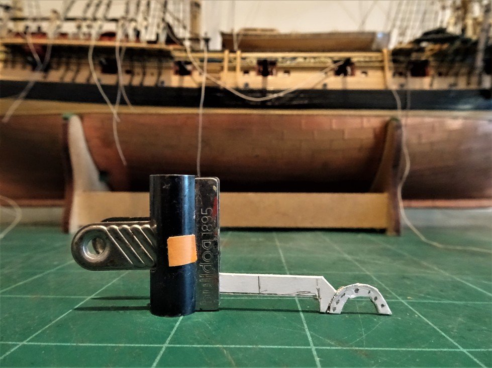
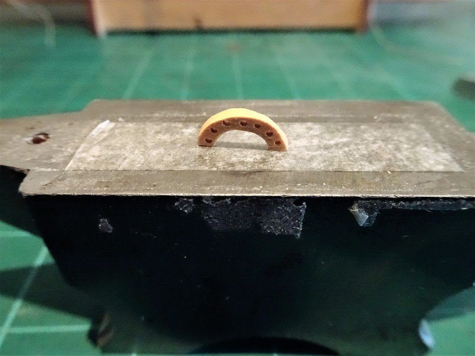
Hatch Guard Rails. I wanted to replicate something more realistic than simply using long stemmed eyebolts with line threaded through, but my usual fudges are insufficient to meet the needs of doing this. A new skill set is required that is Silver soldering. To make the stanchions I will be using 0.8mm diameter micro bore brass tubing and 0.3mm brass etched eyelets. (Caldercraft) Two of the brass eyelets are required to be fixed to the stanchion towards the top at right angles to each other. Here is the raw material for the makings. Those who are familiar with the Caldercraft 0.3mm brass etched eyelets will be aware of how fine they are. After cleaning the brass tube is held in position on the heat pad and the eyelet is held by self closing tweezers. A tiny amount of ‘medium’ paste is applied to the stanchion. The eyelet put on top of it and the heat applied, all done in seconds. For the second eyelet ‘easy’ paste is used (to avoid melting the solder on the first), again a matter of seconds and it’s done. I was amazed that the bond was so good it withstood filing of the ring once I had cut the stem off it, and even bending the eye slightly into a horizontal plane. Good stuff this silver soldering, or brazing as we experts prefer to call it. First tentative fitting:- A lot of cleaning up and finishing to do including finials for the posts, but for me the exercise was a success and the objective achieved. I would recommend this method of fixing fine parts together to those who haven’t tried it; it really extends the possibilities for enhancing a kit, even for a beginner like me. My initial results with the brass rod were successful, but the finials less so, so I searched around for an alternative. The replacement material is stainless steel and I initially had concerns whether the brass eyes would braze satisfactorily to them, no problem. An added advantage is that they are far more robust than the micro tubing. Seems to be the right height in relation to Capt. Silver. Can’t believe how long it has taken to finish these little items, the brazing was the least of it. These finials are a tad over 1mm in size and the stanchions 0.8mm diameter. The blackening process differed, this time I used Carr’s Metal Black for Steel, but it also blackened the brass rings and solder. Oh, the origin of the stanchions..... Donated from William’s dog brush. Not too impressed is he To finish off this section, the railings for the Fore hatch have now been completed. B.E.
- 363 replies
-
- 4
-
-
- pegasus
- victory models
- (and 2 more)
-
Rudder coat and Chains Not the prettiest fitting on a model, but required for the sake of realism rather than have the gaping hole of the helm port on show. I had already fitted a rudder coat made from finest handkerchief cotton, but it needed finishing off. They are tricky things to get right for the shape and to allow sufficient ‘bag’ in the coat to allow for rudder movement. The ffm describes the attachment thus: The wider end is nailed around the inside of the Helmport. The excess loose canvas hangs down allowing the rudder to move freely. I’m not clear whether this means the canvas hem is nailed thro’ the edge of the boards that make up the lower counter or the inside face of the counter boards which would be tricky for access. I had originally coloured the coat as below but have since gone off the brown colour. The hem for nailing around the helm port is made from shaped micro- porus tape pva’d around the coat edge, here in an unfinished state. Painted the coat an off black colour and took the opportunity to tidy up a couple of things on the counter. Noticed I had also lost the eyes to the Spectacle plate, now replaced with slightly more robust versions. Much more satisfied with the new look coat. Rudder chains These are shackled to the Spectacle plate, run up to and along the lower counter and have the Rudder pendants attached to them to aid steering in the event of problems. This is another area where size information is scant. The ffm does make mention of the chain, but David Antcherl supposes in the absence of contemporary information that the links are of 1” iron 3-4” in length. At scale, chain is usually described in links per inch or length/width of the links. Those measurements would equate to a scale chain of 0.4mm diameter with links of between 1.2 – 1.6mm in length. Deciding on the chain gauge for a model can be tricky and result in multiple purchases to get one to suit, minor differences in given sizes can look quite marked when fitted. This sample has 16 oval links to the inch with a 0.3mm dia and 2.3mm in length. It was obtained from http://www.scalelink...aSLCH03#aSLCH03 They call it Medium light chain. Nice chain, Looks ok, but borderline acceptable for scale, strikes me as just a tad heavy. Here the Scale link chain is on the port side, and an alternative Artesania Latina 1.5mm oval chain, on the Starboard side. The scale link chain by comparison has a flatter profile and is of a heavier gauge. Here is the AL chain fitted to both sides in close-up. There are 19 links to the inch with a diameter of 0.3mm. and a length nearer 2mm than 1.5mm. The width of the links is 1.6mm. The code number of the AL chain is AL8608. Overall I think it has the edge, and this is the one I will use. Three hooks are set along the counter onto which the chains are secured when not in use. B.E.
- 363 replies
-
- 2
-
-
- pegasus
- victory models
- (and 2 more)
-
..... His name was Chuck, Chuck Passaro, and he designed the sweetest lantern in the West. An hexagonal lantern that is just right for Pegasus. http://www.syrenshipmodelcompany.com/ I could no way match this so my own feeble efforts were quickly put aside. What a great little lantern this is. This photo shows the lantern at near real size and just how small it really is. The moment of truth – a trial fitting on Pegasus...... A vast improvement in the look from my previous effort and the style suits Pegasus so much more. Well done Chuck, and thanks for designing this fine little lantern kit. B.E.
- 363 replies
-
- 2
-
-
- pegasus
- victory models
- (and 2 more)
-
The Stern Lantern I have had a couple of previous attempts at making a lantern using the Caldercraft etched lantern set for their 1:72 scale Victory model. The main issue is that the style and number of glazed sections within the octagonal shape are too many, and the octagon shape is not quite the style. From around 1707 the standard pattern on British ships was hexagonal. This is the larger central lantern from Victory, unmodified, and I put it together to get a feel of how the thing would look. I don’t like it and it will not stand. Slightly too big and too many glazing bars to sit comfortably with scale. The side lantern at 21mm high is pretty fair for scale to suit the Pegasus at 1:64. Here with reduced glazing bars. For this I trialled using acetate windows fixed with epoxy. Messy business and the result was an unholy mess. I persevered with various versions. I think the size sits well with Pegasus, and the style doesn’t look altogether out of place, but I'm still not entirely happy. The execution could have been better but the principle is established as basis for modifying the Caldercraft Victory lantern to better suit the Swans at 1:64. But..... just when I thought I would have to settle, a saviour rode out of the West. B.E.
- 363 replies
-
- 2
-
-
- pegasus
- victory models
- (and 2 more)