
HOLIDAY DONATION DRIVE - SUPPORT MSW - DO YOUR PART TO KEEP THIS GREAT FORUM GOING! (Only 72 donations so far out of 49,000 members - Can we at least get 100? C'mon guys!)
×
.JPG.ca33079f5815b861e67b9c2cccd37982.JPG)

Blue Ensign
-
Posts
4,564 -
Joined
-
Last visited
Content Type
Profiles
Forums
Gallery
Events
Everything posted by Blue Ensign
-
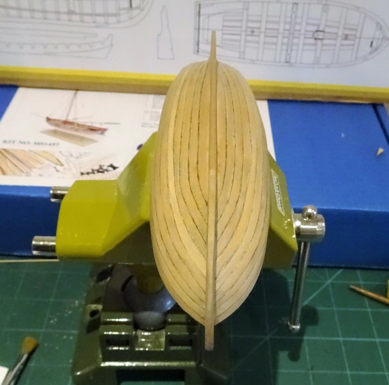
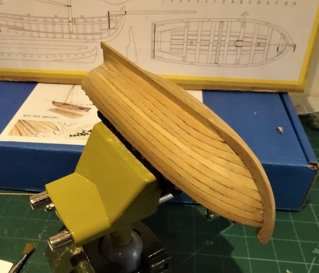
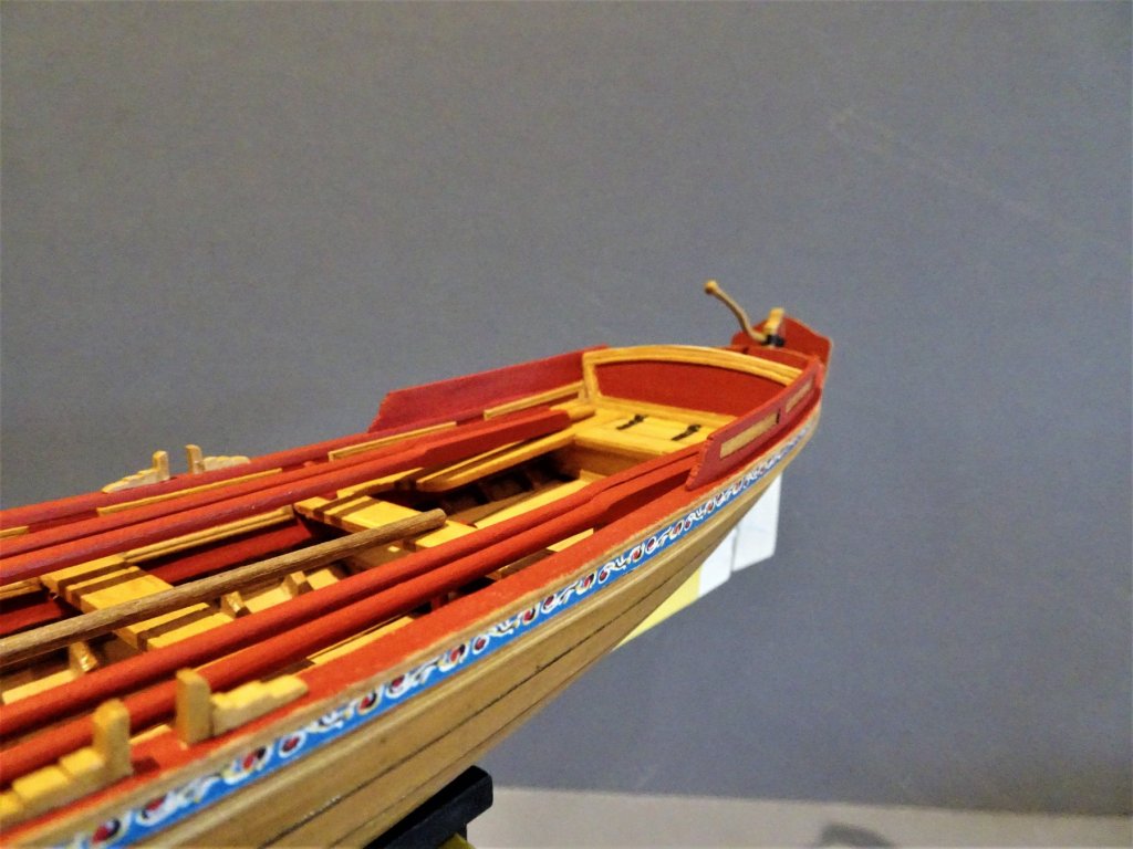
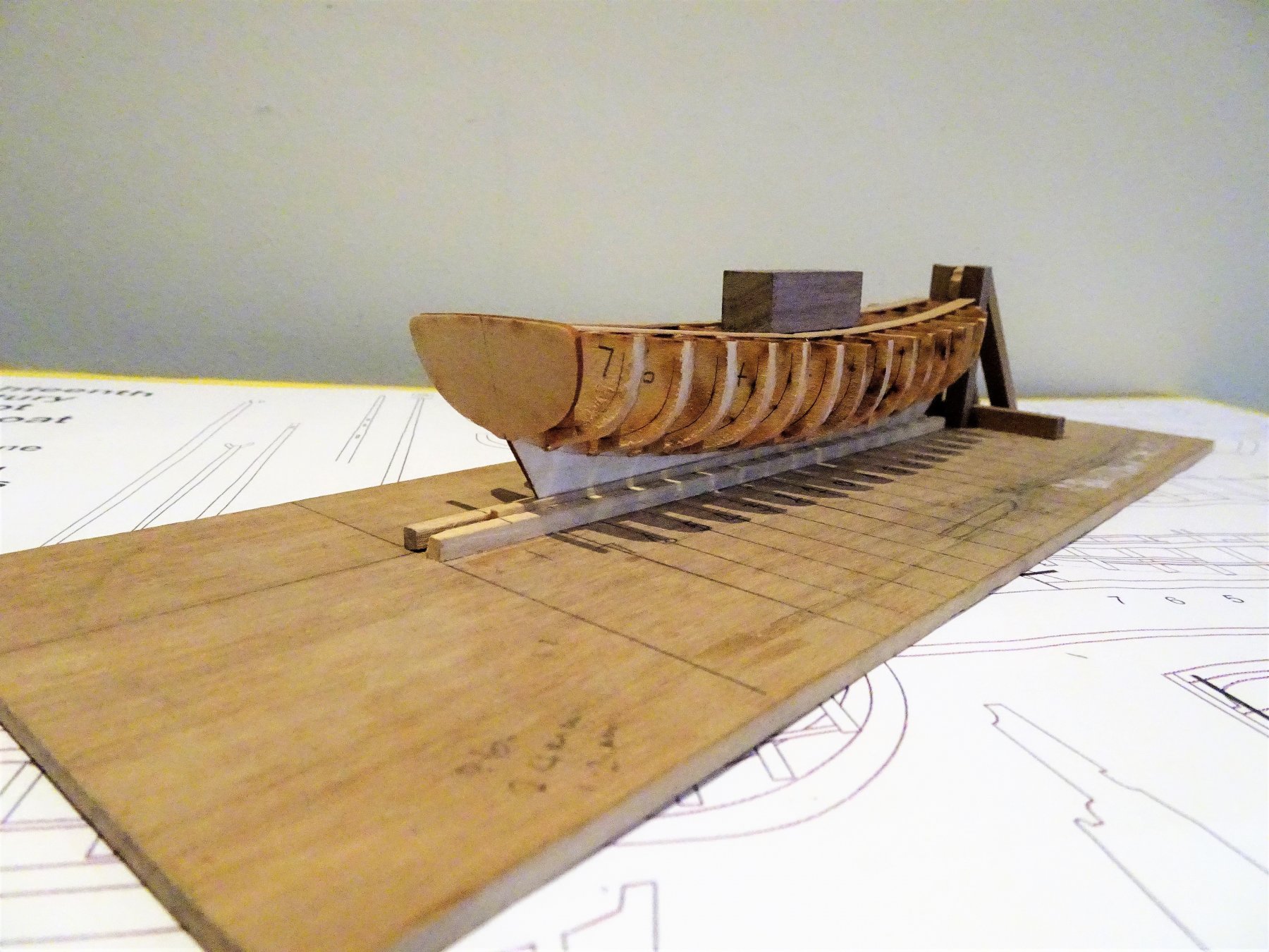
 Thanks for your support guys. Planking is now completed. I planked alternatively from keel and Gunwale with the aim of getting the final strake just below the waterline level. 1206 1207 Worked out fairly evenly along the hull for the final spiled plank. 1208 The final plank shape was marked on tape over the hull and transferred to a broader plank to cut out. It was then a case of sanding/scraping by degrees to fit it along the hull. 1209 Final strips in place. 1210 1212 The hull now needs fine sanding and a little fettlin' to fill any hairline cracks along the plank joints. Relieved that this part of the build is completed, still not overjoyed with the planking, but it has turned out somewhat better than the Pinnace in that there is greater thickness of material left on the hull at this stage, just as well perhaps as the starting thickness was only 0.6mm. I will now spend some time cleaning up the hull before I remove the bulkhead centres. B.E.
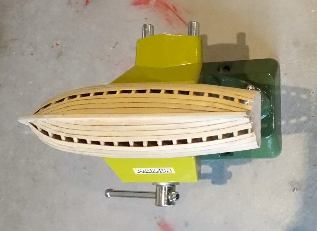
- 91 replies
-
- 15
-

-
- 18th century longboat
- model shipways
- (and 1 more)
-
I would have been very happy with that outcome Steve, nicely done. B.E.
- 190 replies
-
- 1
-
-
- pinnace
- model shipways
- (and 1 more)
-
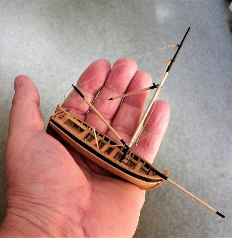
However you decide to finish her Jason she will be a stunning model. I had the same issue about fully rigging a model when I built my Victory, mainly around the space she would take up. I have always liked the look of models rigged with just the lower masts and standing rigging, ever since I saw a drawing by Bjorn Landstrom in his book The Ship. So I finished her on this basis, altho' I did include the Topmasts in the lowered position 'just in case' I decided to return one day to fully rig her. (which won't happen) Models rigged to this level are far more manageable whilst still allowing some added interest, and the absence of yards makes a huge difference in display options particularly in a domestic setting. Regards, B.E.
.thumb.JPG.78b3b9698df2499b4d33d6a75fb982d7.JPG)

-
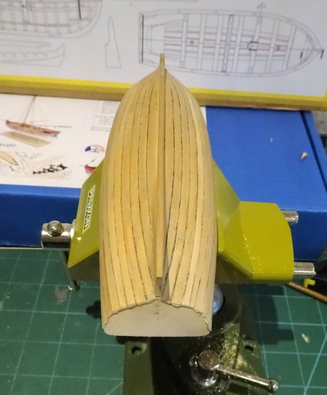
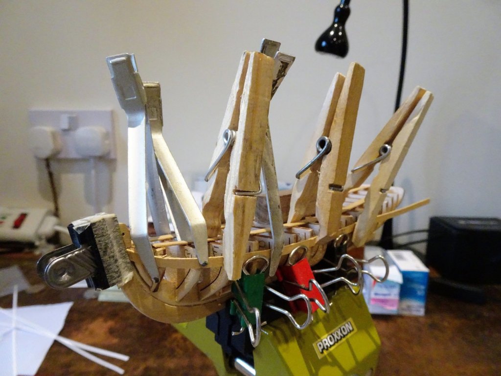
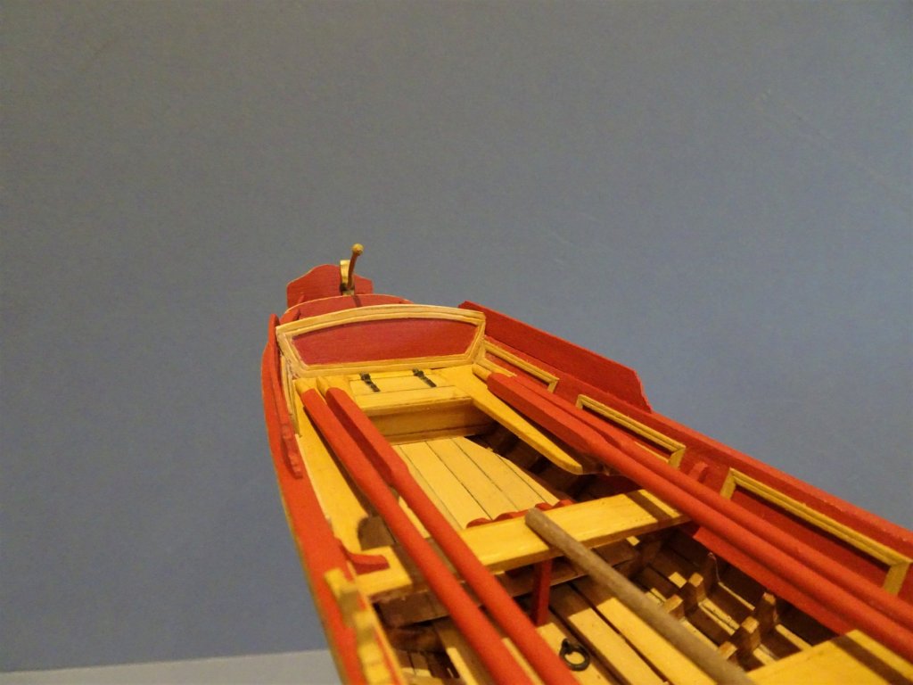
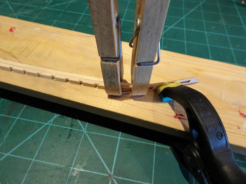
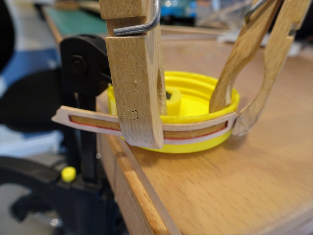
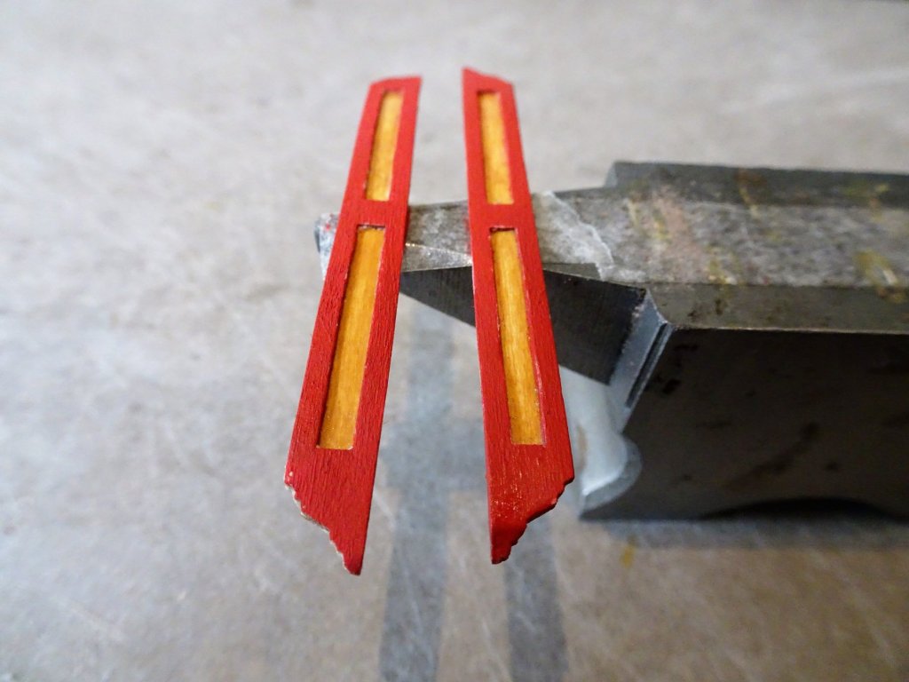
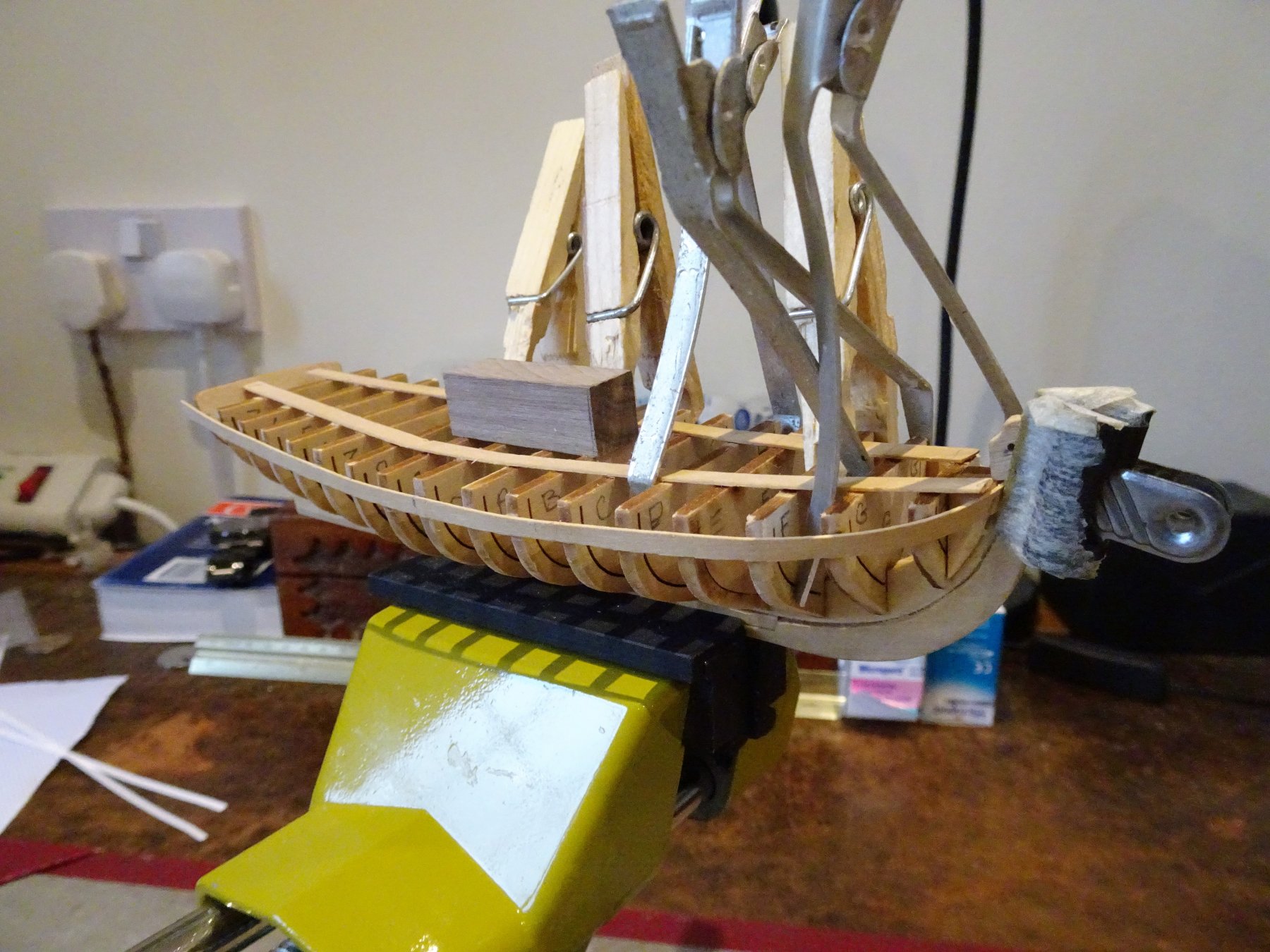
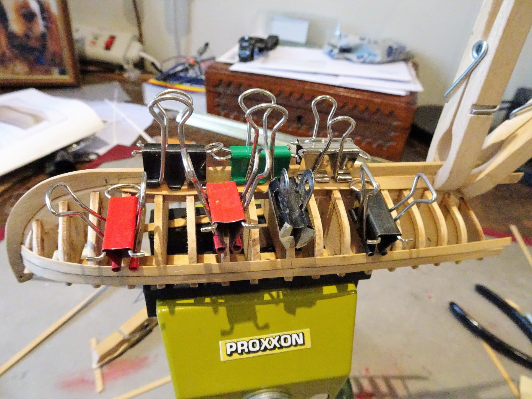
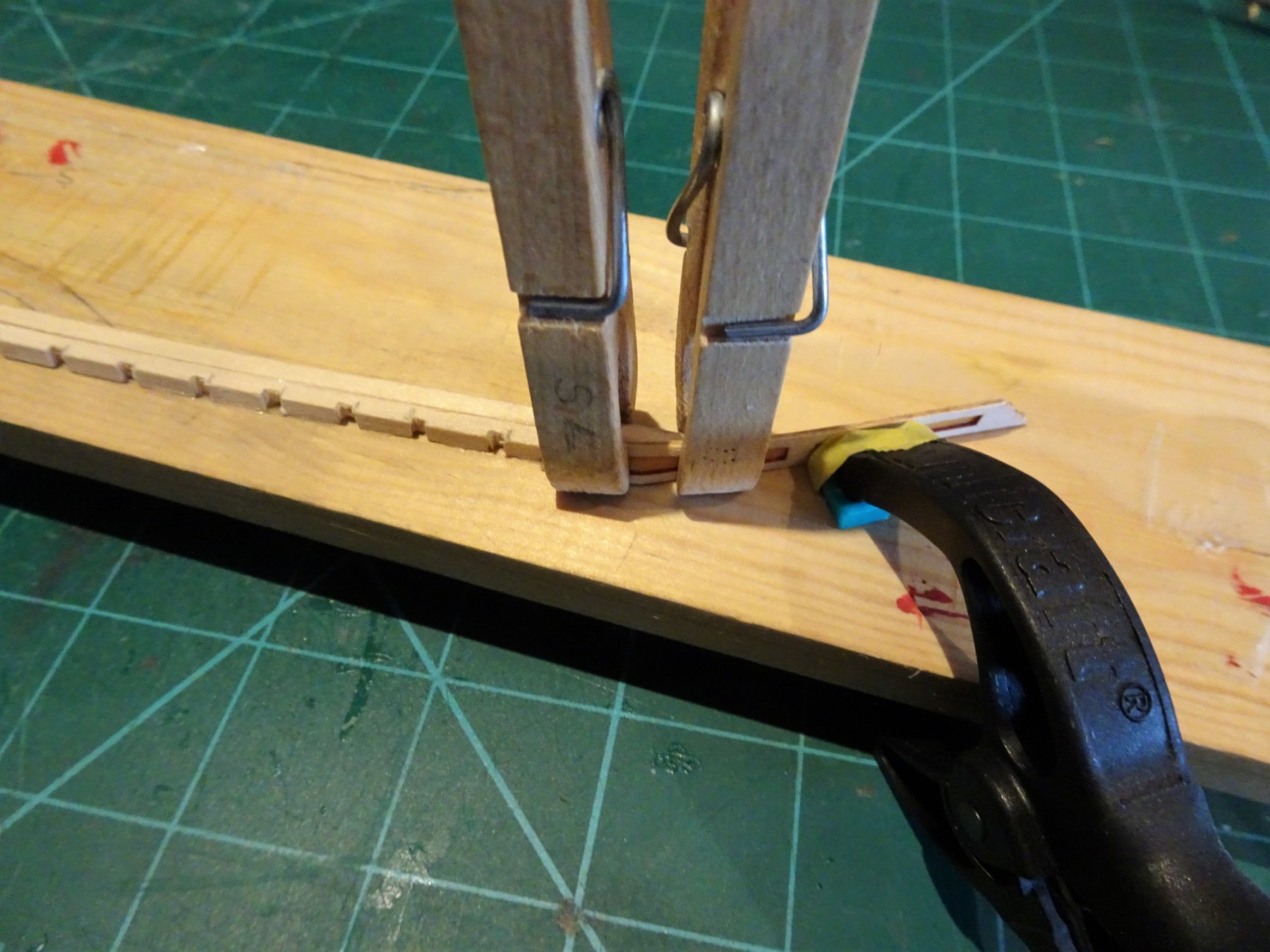
Thank you Michael, kind of you to say so, but I was definitely thinking of my skills Time to think about planking. The kit provides Limewood planks of ⅛" strips which equates to 3.2mm. I will be using Boxwood strips of 3.4mm. The kit strips are of 1/32" thickness,( 0.79mm) my Boxwood stuff is a nominal 0.6mm. I would have liked a tad thicker but the required lengths are fairly short, and they will (should) be fairly easy to manipulate. I added the transom piece, but to provide more security I drilled and pinned this piece thro' into the False keel. 1123 The sheer line was marked off on the bulkheads and a sheer line template made to form the sheer on the top planking strip. 1126 There is not a lot of room for clamping the strips during glueing on this little model. I use an assortment of modified spring clips, modified clothes pegs, and mini bulldog clips. 1128 Not a lot of pressure is applied using these but it is sufficient providing the planks are properly wet/heat shaped to remove tension. I use a good quality pure pva with a five minute grab. 1134 The first two strakes below the sheer went on without problem, and these add greatly to the stability of the hull especially the transom board. 1131 I then turn my attention to the Garboard strakes. For these I use 4.5mm wide strip. 1141 1143 1139 Planking will now continue to completion. B.E.


- 91 replies
-
- 16
-
-
- 18th century longboat
- model shipways
- (and 1 more)
-
I felt very much like you do at this stage of the build, quite dissatisfied with the look of the planking in small areas. I think I would try the fill with sawdust/glue mix where the second plank meets the third, but if the result stood out, I think I would just remove the offending plank and spile a replacement. If you used pva it should be not too traumatic to remove the plank cutting thro' between the bulkheads, and easing off where glued by careful wetting with a paint brush point on the join. B.E.
- 190 replies
-
- 6
-
-
- pinnace
- model shipways
- (and 1 more)
-
Looks pretty clean to me Steve, and certainly better than mine was at that stage. Plank thinness seems to have afflicted several builders me included, but unless there is light behind it I found it not to be too problematical once the hull had been varnished, and in my case painted below the waterline. B. E.
- 190 replies
-
- 8
-
-
- pinnace
- model shipways
- (and 1 more)
-
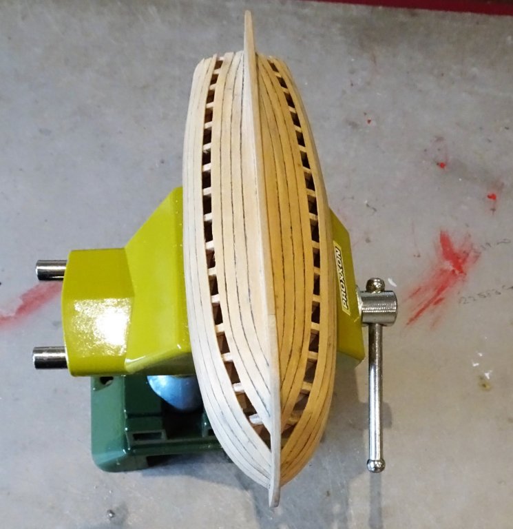
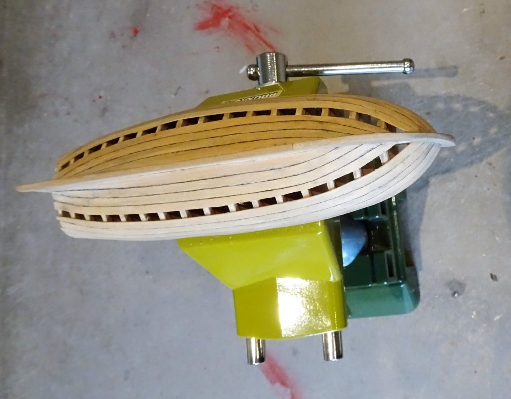
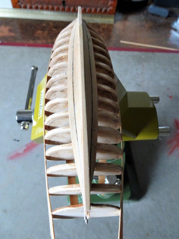
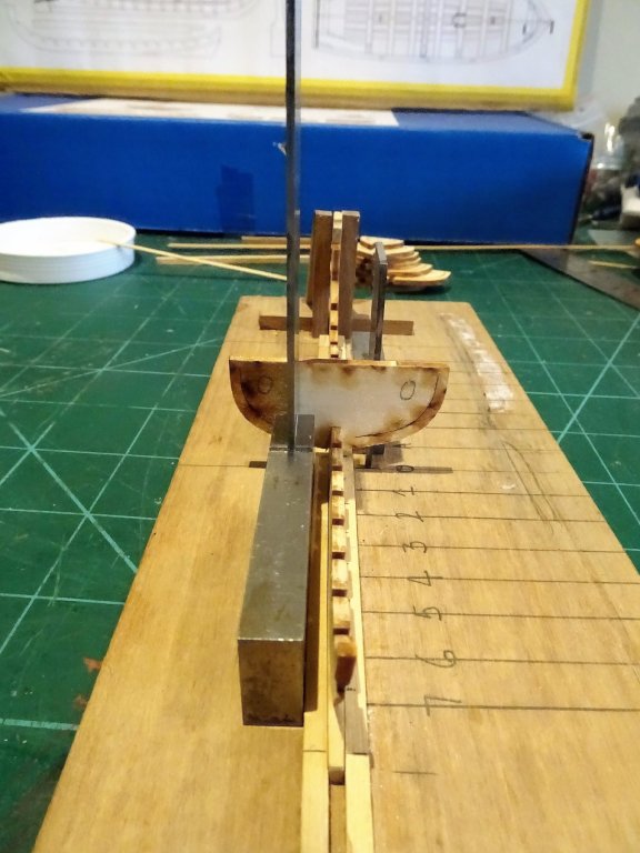
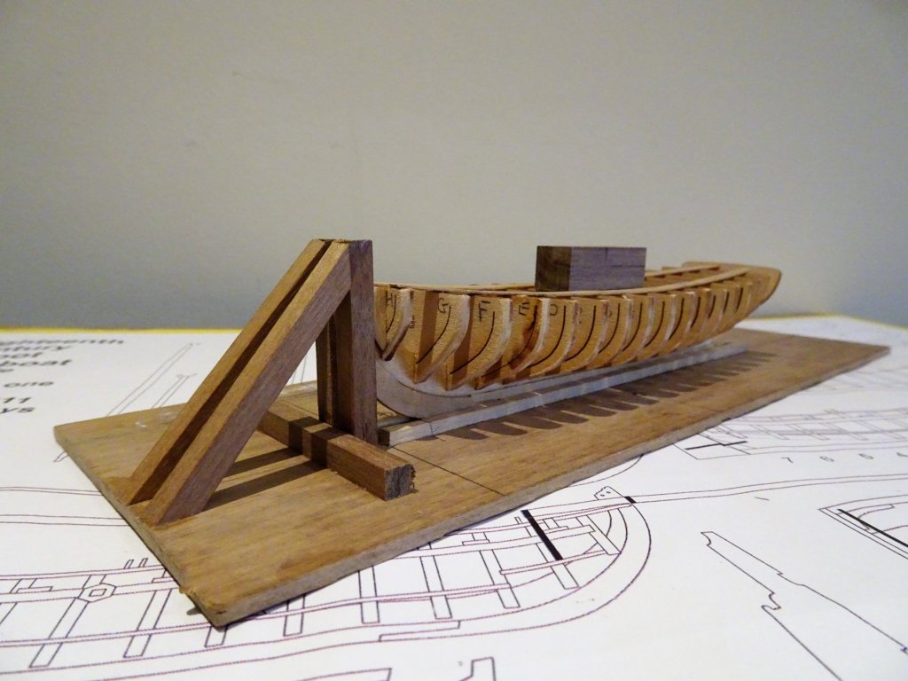
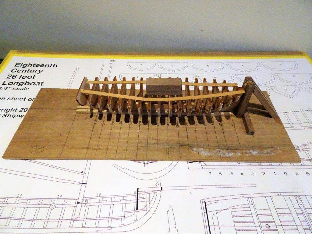
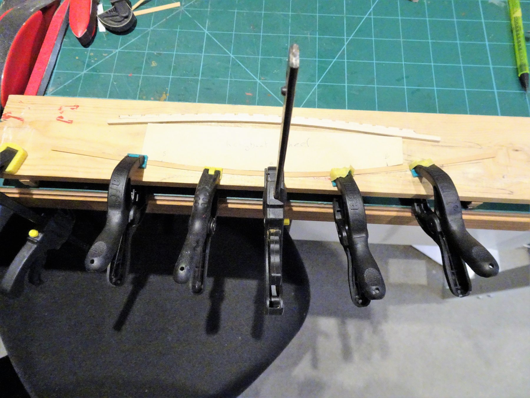
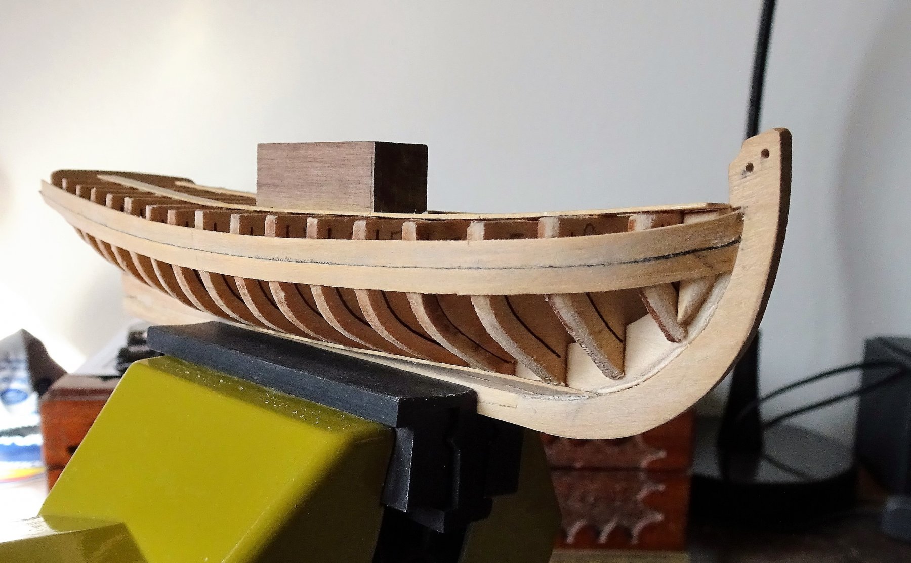
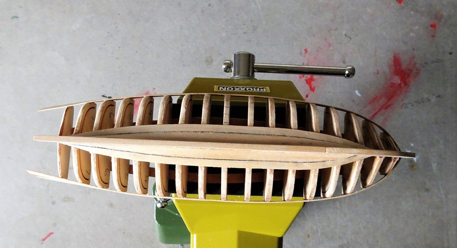
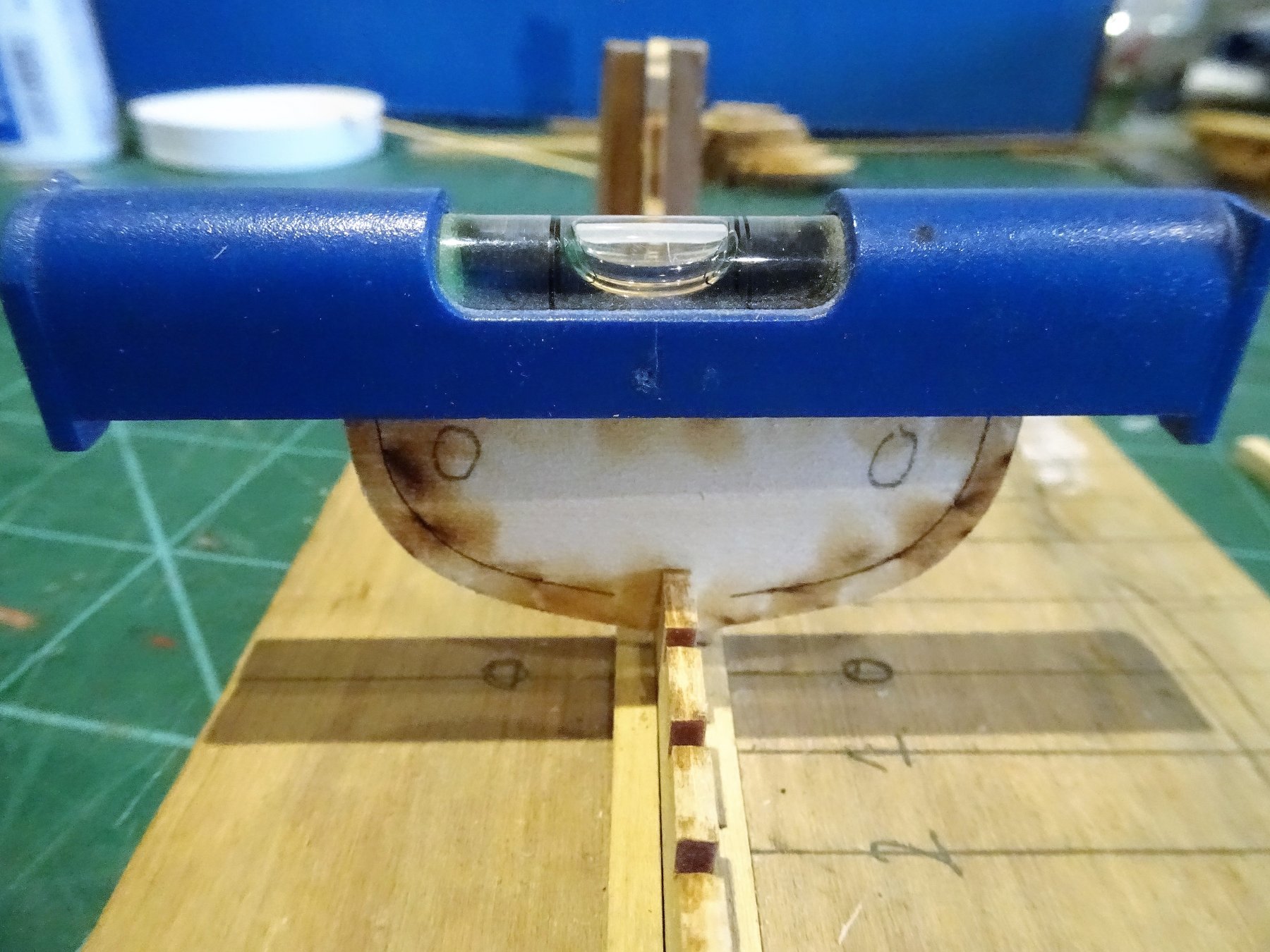
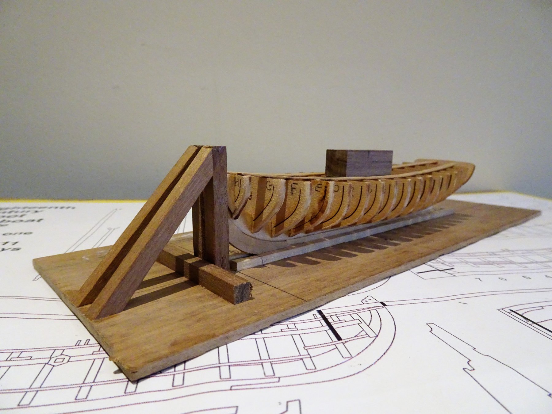
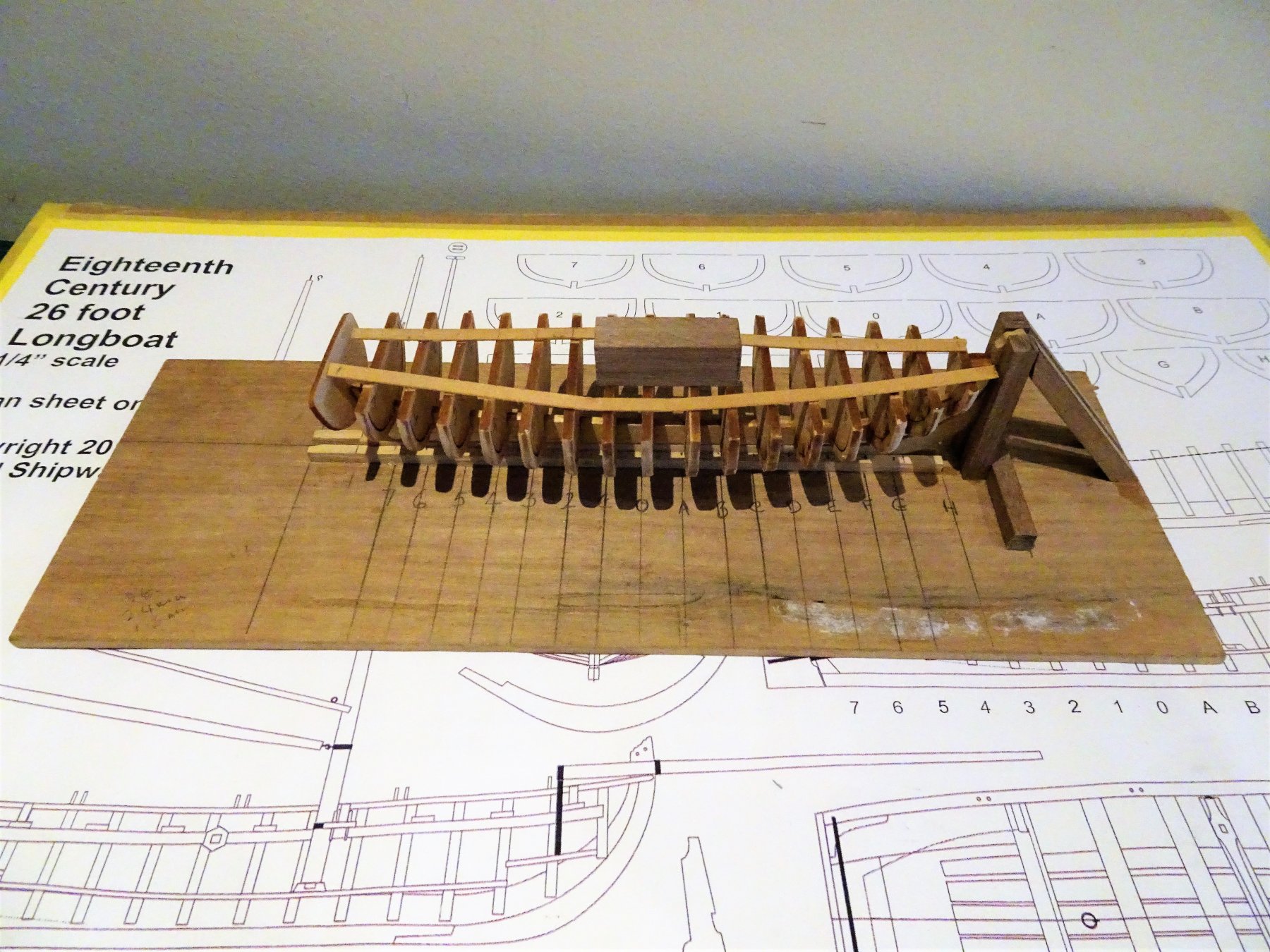
With the keel proper added the assembly can be secured in the simple building board, and the process of adding the bulkheads can begin. 1092 I always start by fixing the centre bulkhead and then work fore and aft to ensure they are all lined up and set square to the keel. 1094 I use two Engineers Squares to check each Bulkhead is vertical and square to the keel, and mini levels for the horizontal line across the top. 1119 With the bulkheads in place I stick two bracing strips across the tops to help brace the bulkheads against the fairing process. The block on the top is to secure the boat inverted in a vice. 1114 Nothing fancy about the building board, just sufficient to hold the keel and stem in place. 1114 Fairing has just started in this shot, I don't bother to remove the char at this stage, it will clear soon enough and helps to show the fairing line. B.E.


- 91 replies
-
- 15
-
-
- 18th century longboat
- model shipways
- (and 1 more)
-
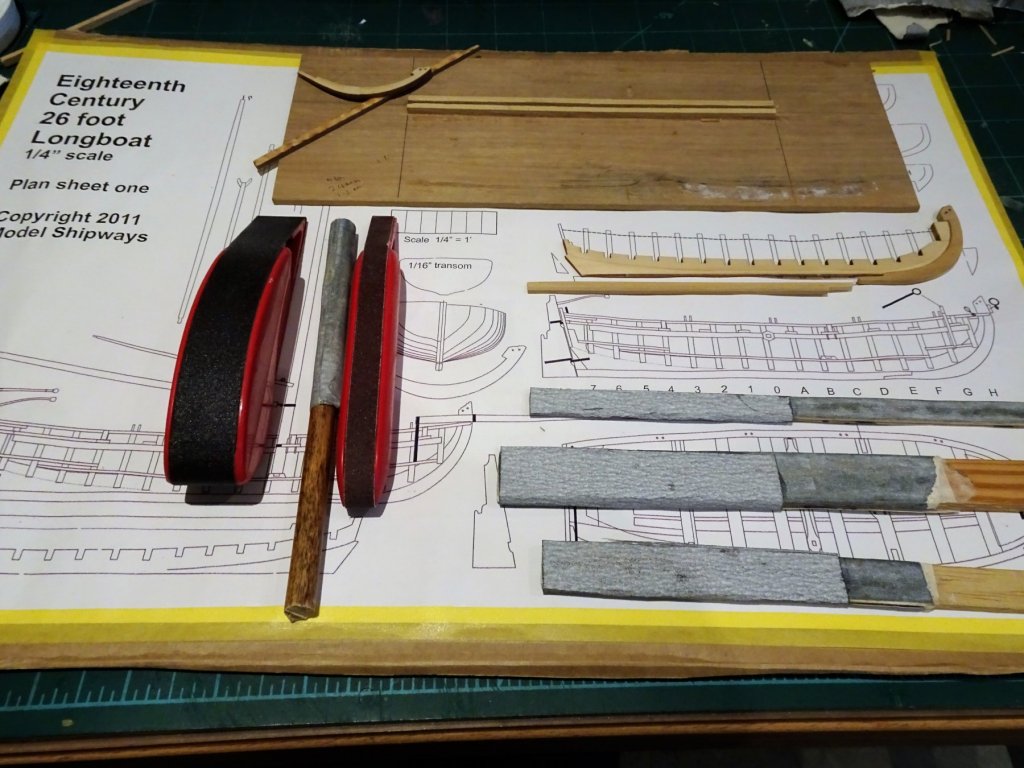
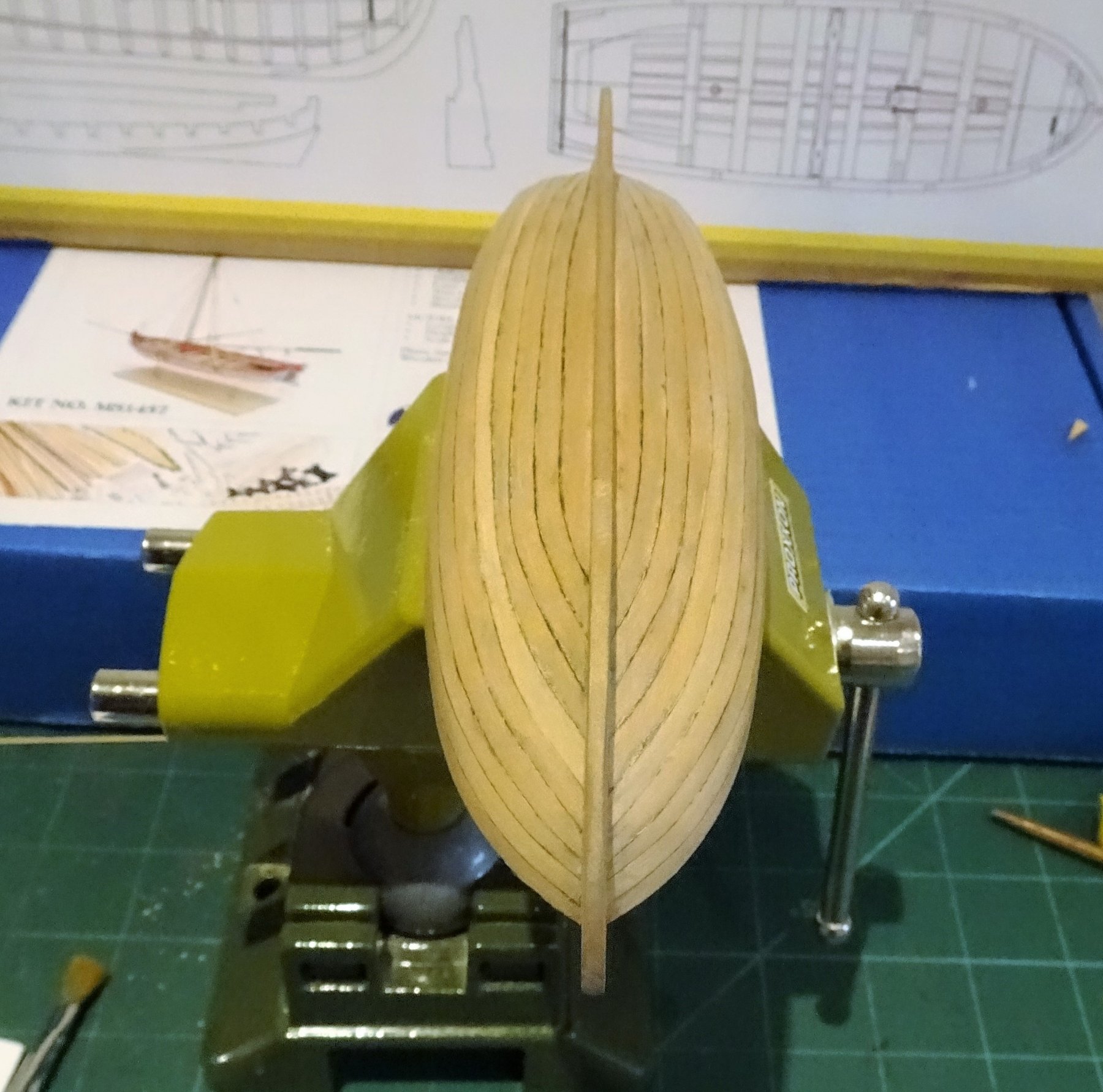
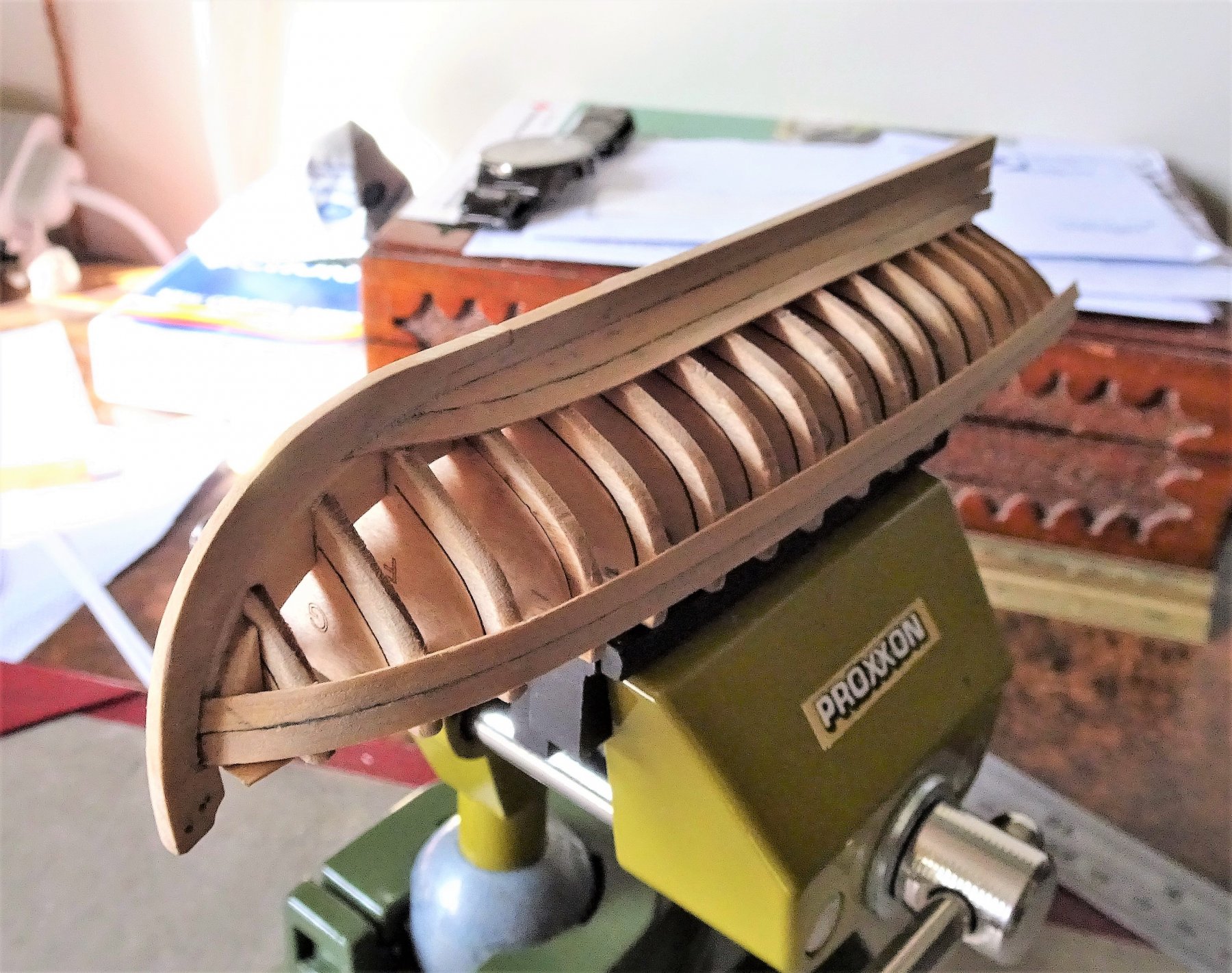
Cheers Guys, Work begins cutting out the replacement stem and keel in Boxwood. The kit parts provide the templates. 1076 The false keel is prepped with the bearding lines cut in and the 'false' rabbet carried up to the stem. One of the problems I found with the Pinnace kit was the softness of the Basswood stem, making it susceptible to dinks and scarring. 1077 The false keel is fairly fragile and I managed to break off the top part whilst trial fitting the stem. At least the Boxwood stem will be more robust than the Basswood version. This is the time to also renew my sanding sticks and prepare a simple building board to secure the keel. B.E.
- 91 replies
-
- 13
-
-
- 18th century longboat
- model shipways
- (and 1 more)
-
Love the photo's of your build Michael, although not intended, that last photo could so easily be a depiction of 'battle' damage, dislodged woodwork, and a jumble of rigging, looks very realistic. B.E.
-
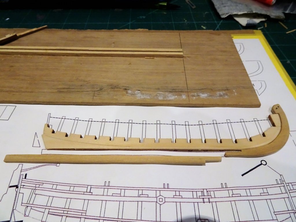
18th Century English Longboat by Blue Ensign - MS 1:48 Scale. The second of the Model shipways kits which I am moving straight onto whilst I'm in the mood, and hoping to improve on my Pinnace build. As with the Pinnace I have 'previous' with this kit having already scratched a 1:64 scale version for my Pegasus build, from Chuck's plans. 1083 057 It was quite small with an hull length just shy of 4" so one might think a larger kit should prove easier. Not necessarily, I found I had more trouble with the 1:24 scale kit Pinnace than the scratched 1:64 version. I will use the kit provided false keel and bulkheads, but this time around I will replace the stem and keel with Boxwood. My aim is to otherwise not use any of the provided kit wood. The hull will be planked with Boxwood strip, slightly thinner than the provided Basswood, but this should be less problematic on the smaller Longboat than it proved to be on the much larger Pinnace. I now need to get the preparatory work done before I start assembly. B.E.

- 91 replies
-
- 10
-
-
- 18th century longboat
- model shipways
- (and 1 more)
-
Love that Binnacle cabinet Bob, a fine piece of joinery. B.E.
- 682 replies
-
- 4
-
-
- halifax
- lumberyard
- (and 1 more)
-
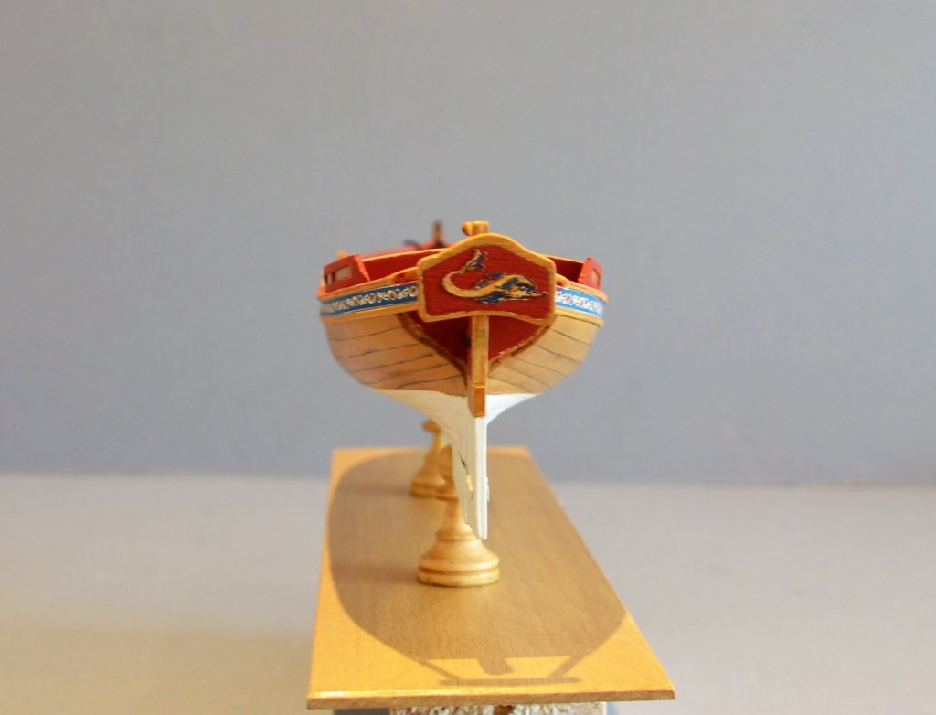
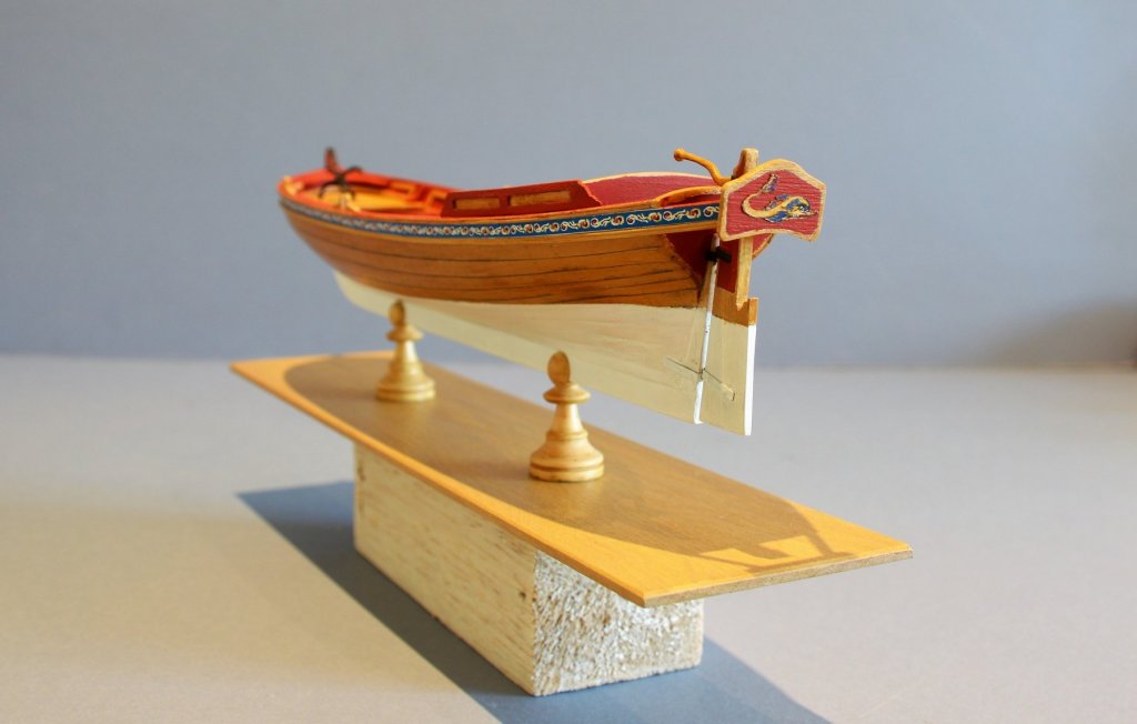
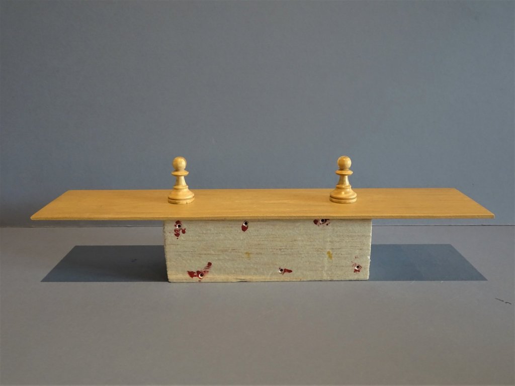
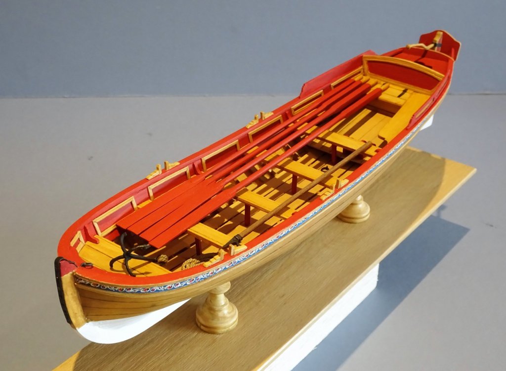
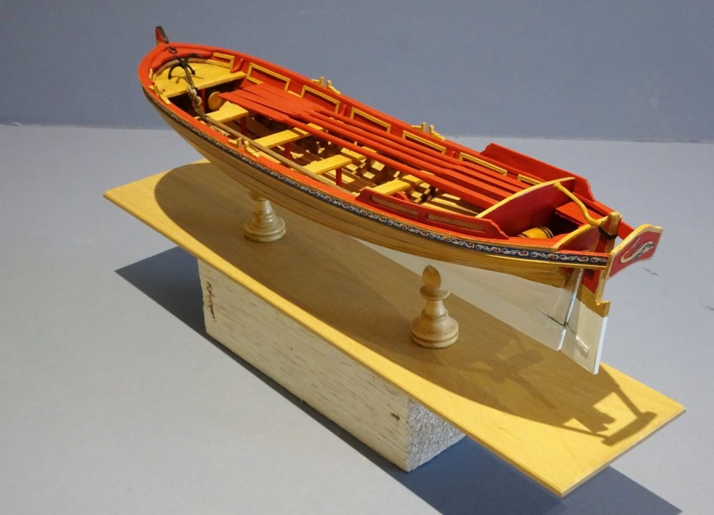
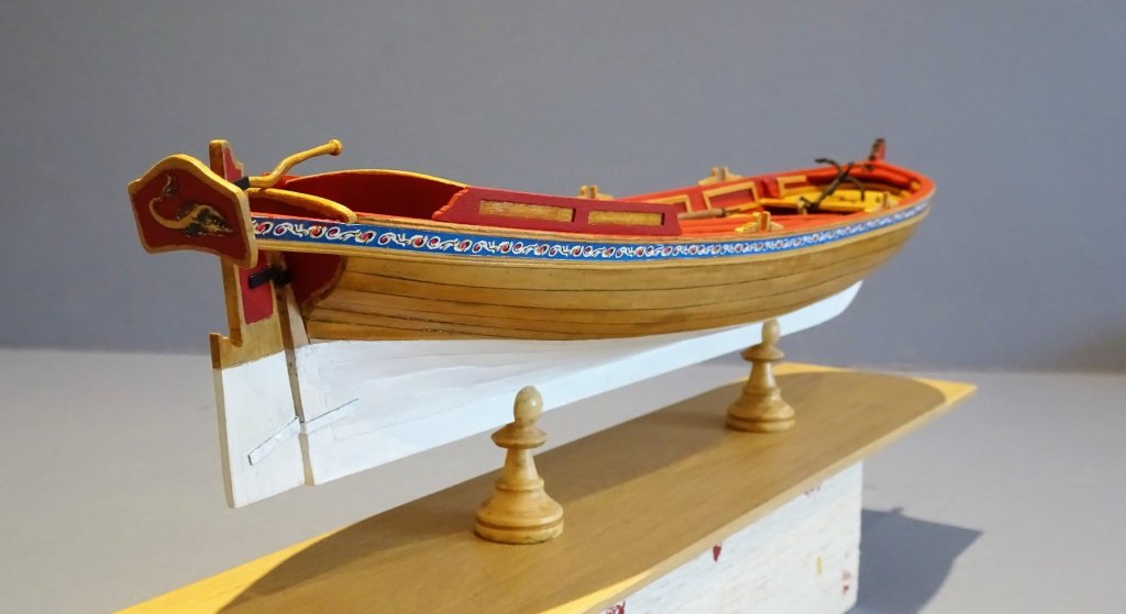
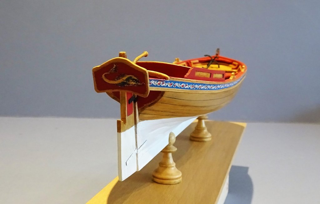
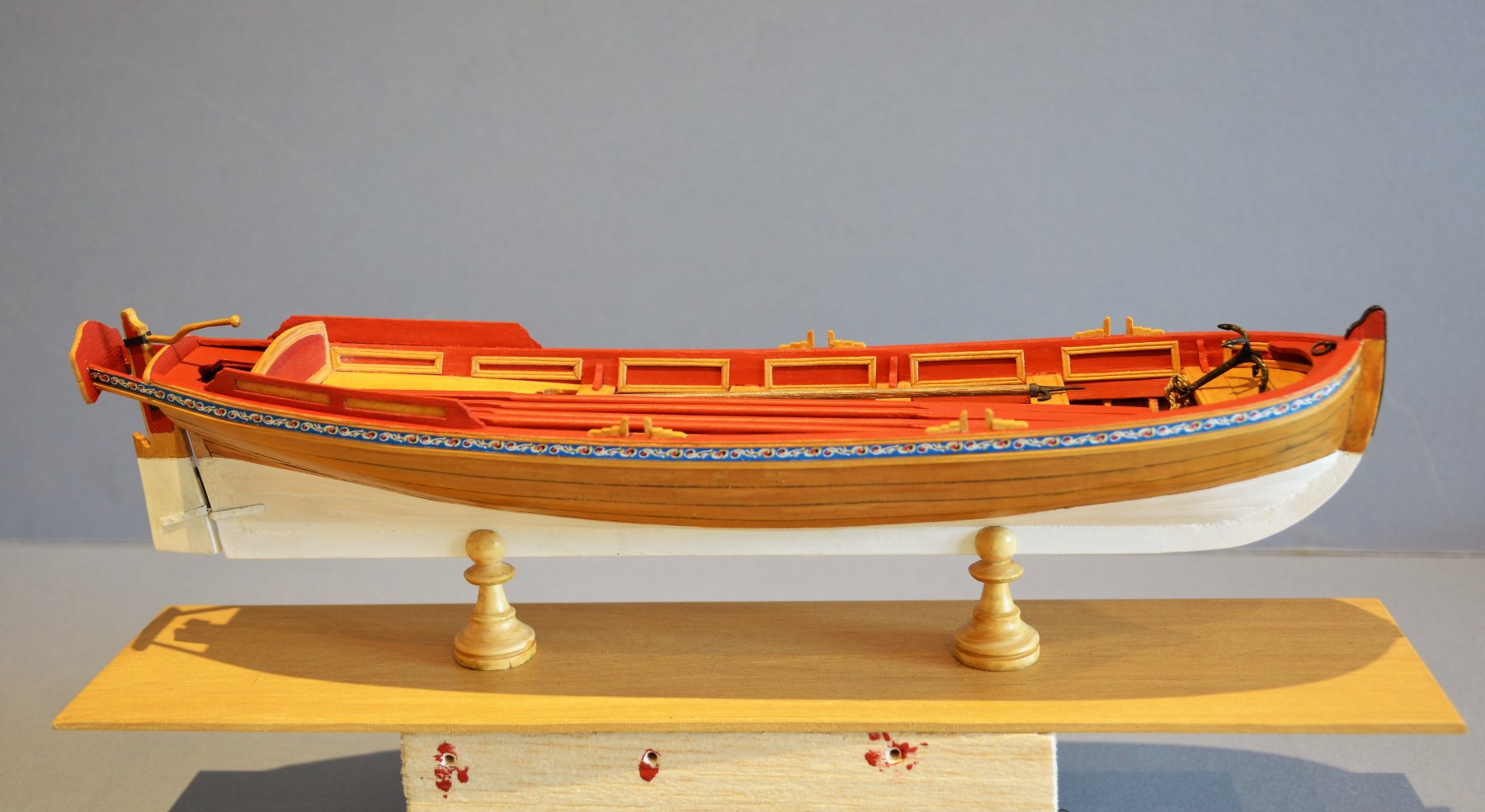
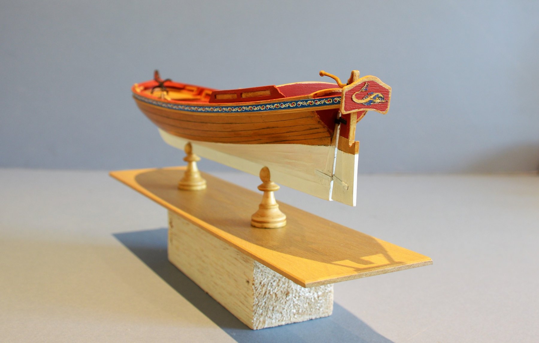
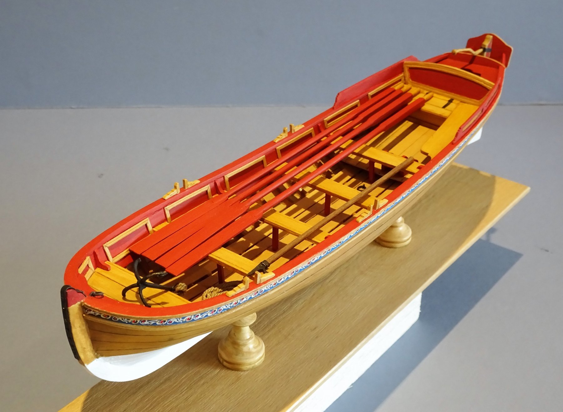
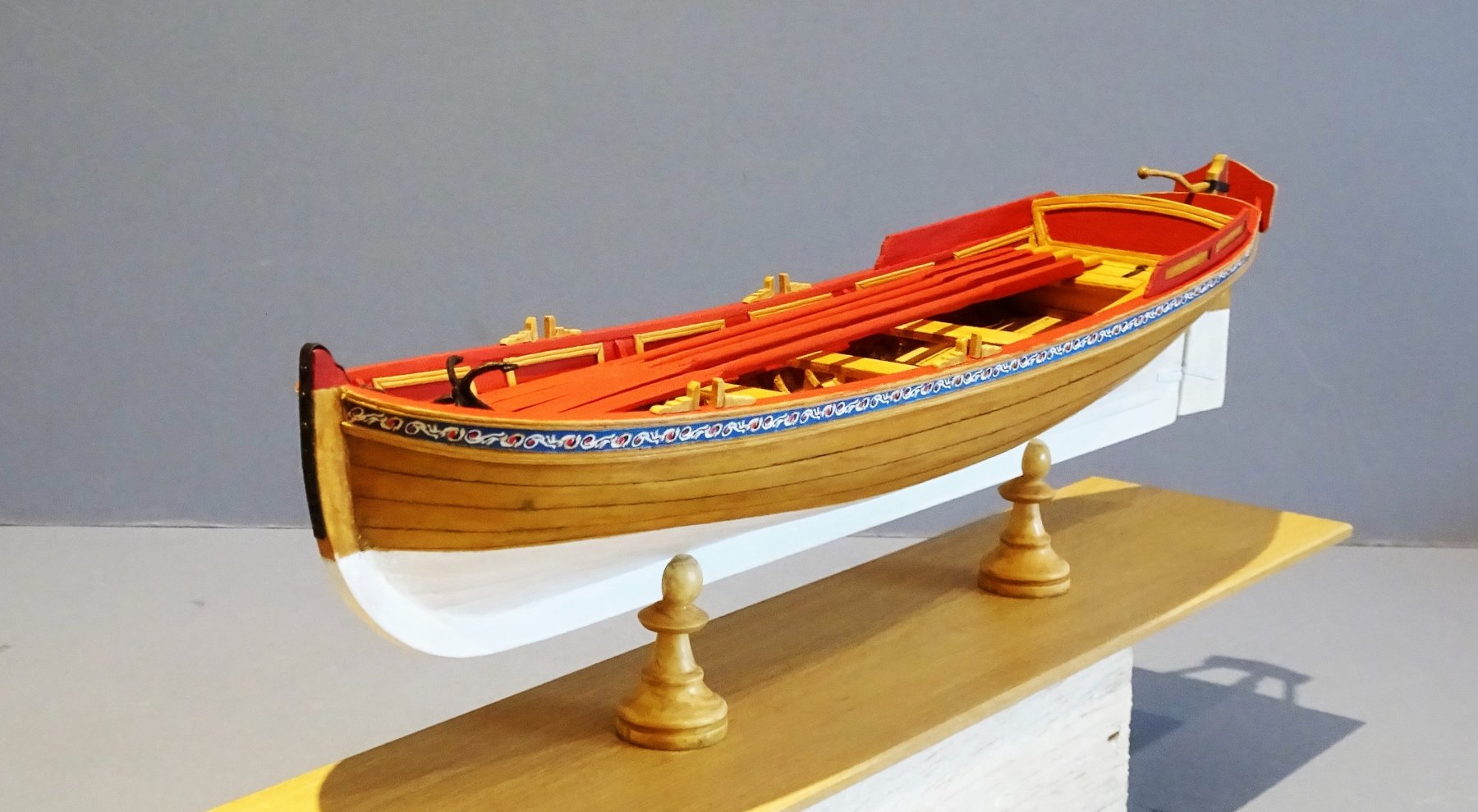
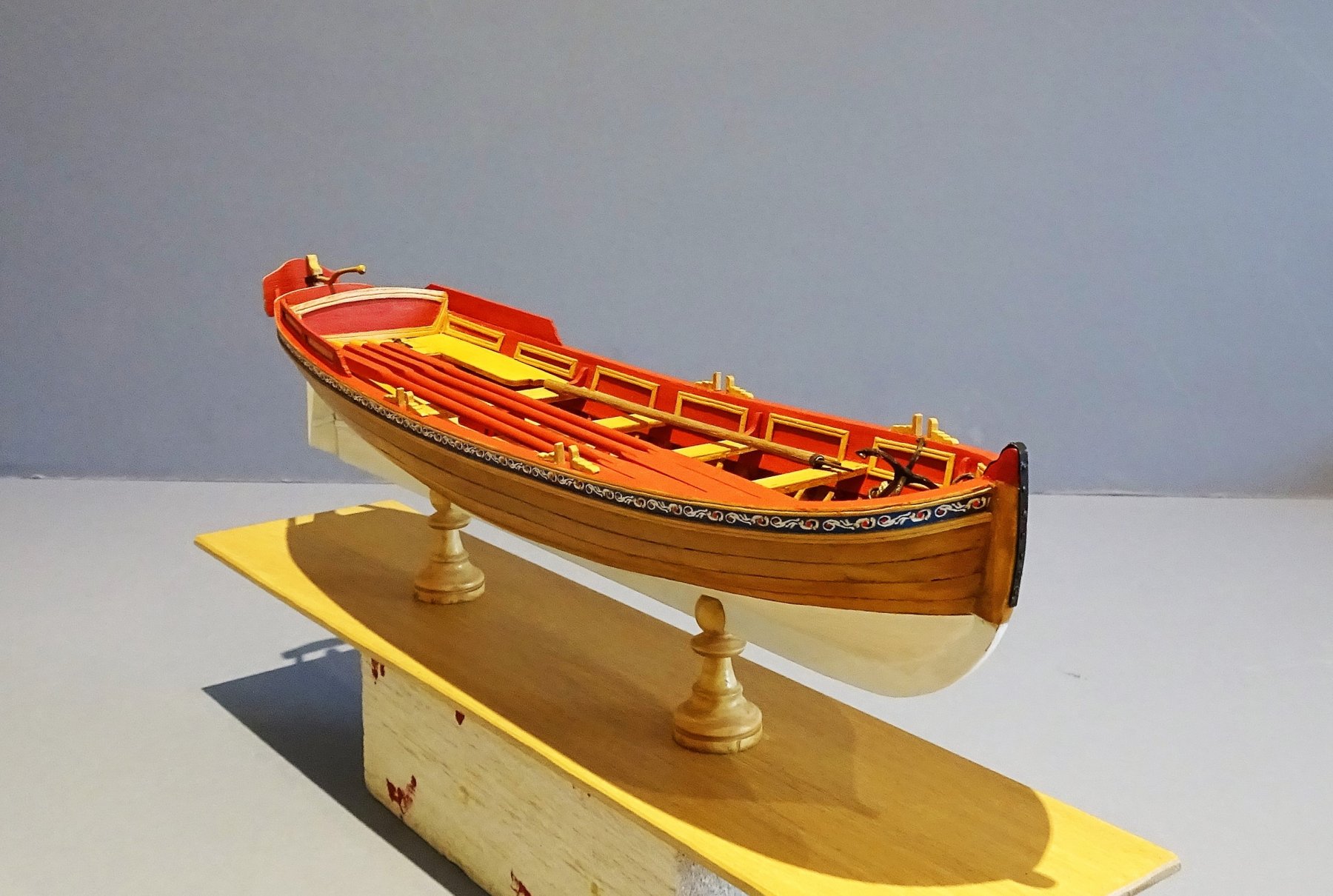
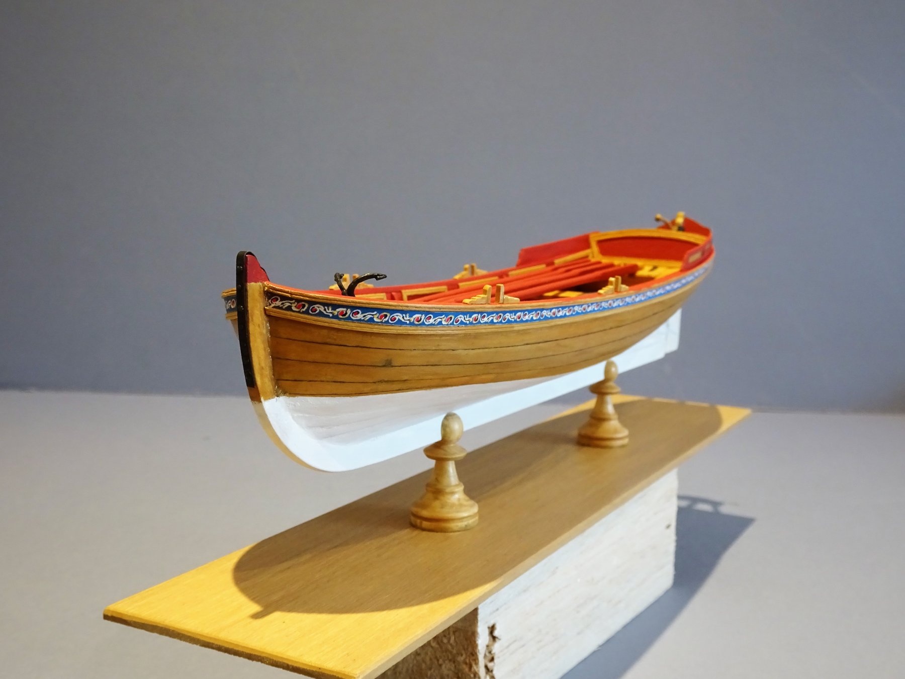
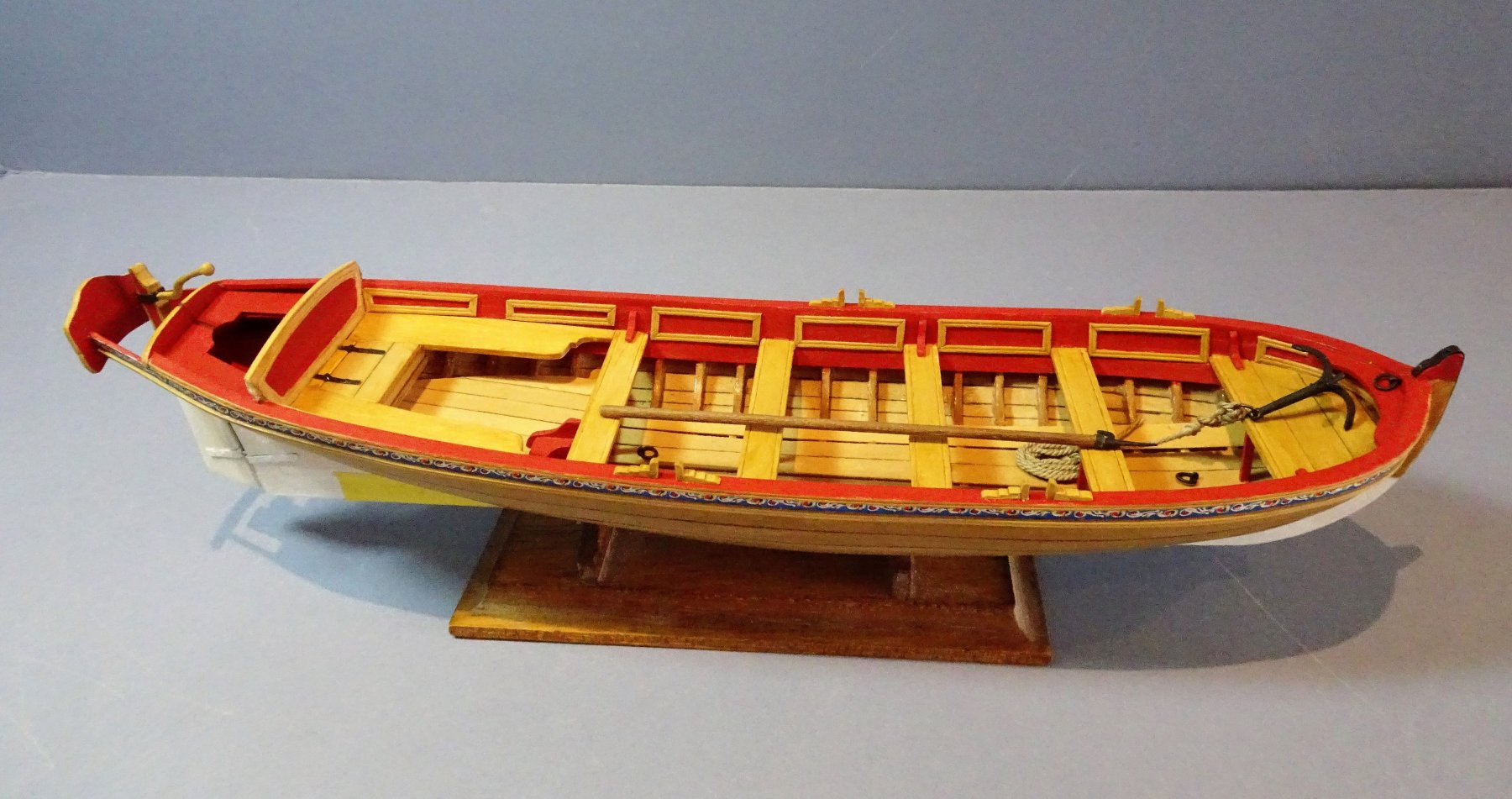
Thank you Bob, Grant, Michael, Martin, Steve, and Christian. So this build is completed after a leisurely five month exercise. The final item to make the base board and hull supports. 1034 For the base I have used a plain piece of Boxwood sheet of 3mm thickness with slightly chamfered edges. 1036 You may recognise what I enlisted into service for the supports. 1037 For a change I made a greater effort for the final photo shoot. and here are the results. 0444 0448 0465 0475 0496 0497 1029 1038 1040 1044 1045 1046 1048 1049 1050 1053 1054 1056. Thoughts on the Pinnace kit. My thanks go to Chuck for designing this fine kit and giving us modellers the opportunity to build a nicely scaled model of an iconic 18th c boat. This is a fine little model but a sod to plank, although I did use rather thin Boxwood strip which allowed a very small margin for sanding corrections . The supplied basswood is not really suitable for a model of this single planked type being too soft and feathery to get clean edges. I did replace much of the wood with my stock Boxwood and were I to do it again I would use Boxwood overall albeit of a somewhat thicker strip for the exterior planking, allowing me a little more leeway for my planking deficiencies. I wasn't too happy with my work at the outset but as the build progressed and I got into the detail I eased up on myself somewhat, a model is more than the sum of its parts, and although I don't rate it as one of my best efforts, I do rather like the look of it outside of the prying eye of the macro lens. This has been a nice little five month summer project, not entirely relaxing, but with a satisfying result, and it has wetted my appetite for Chuck's forthcoming Barge kit. Regards, B.E.


- 156 replies
-
- 21
-
-
- pinnace
- model shipways
- (and 1 more)
-
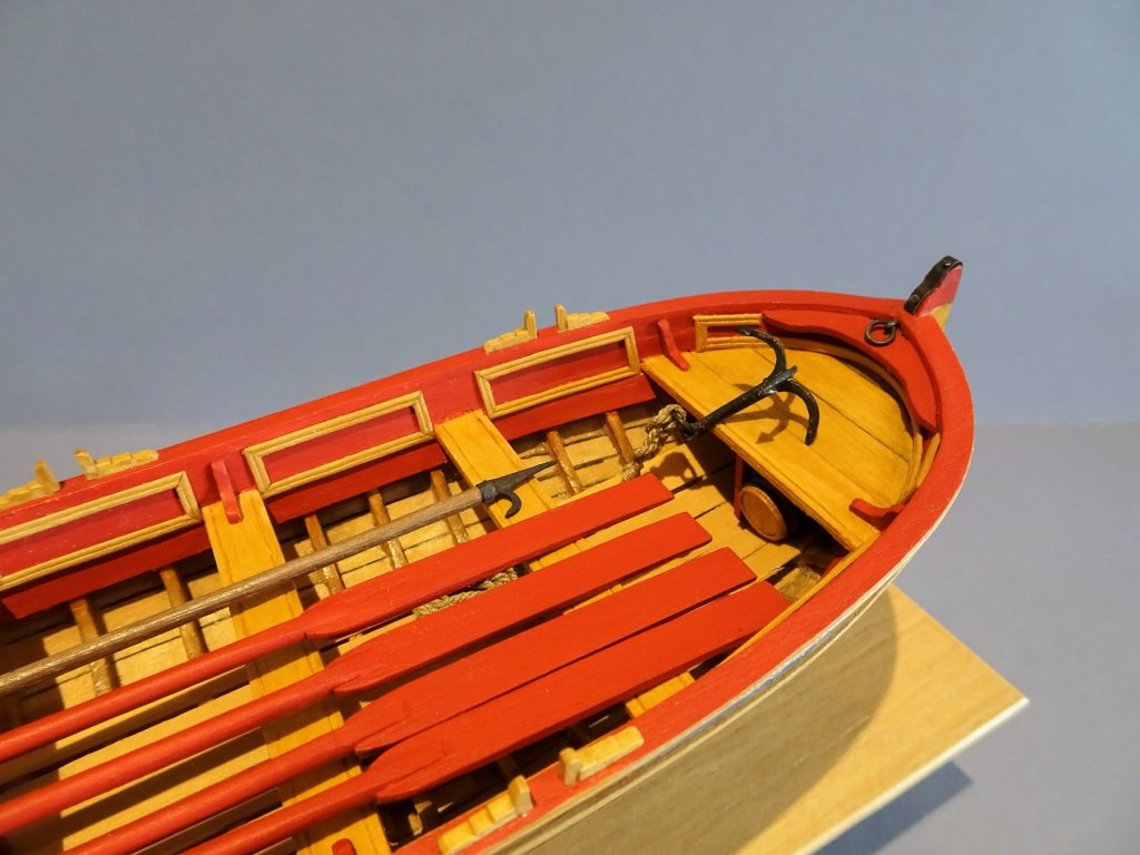
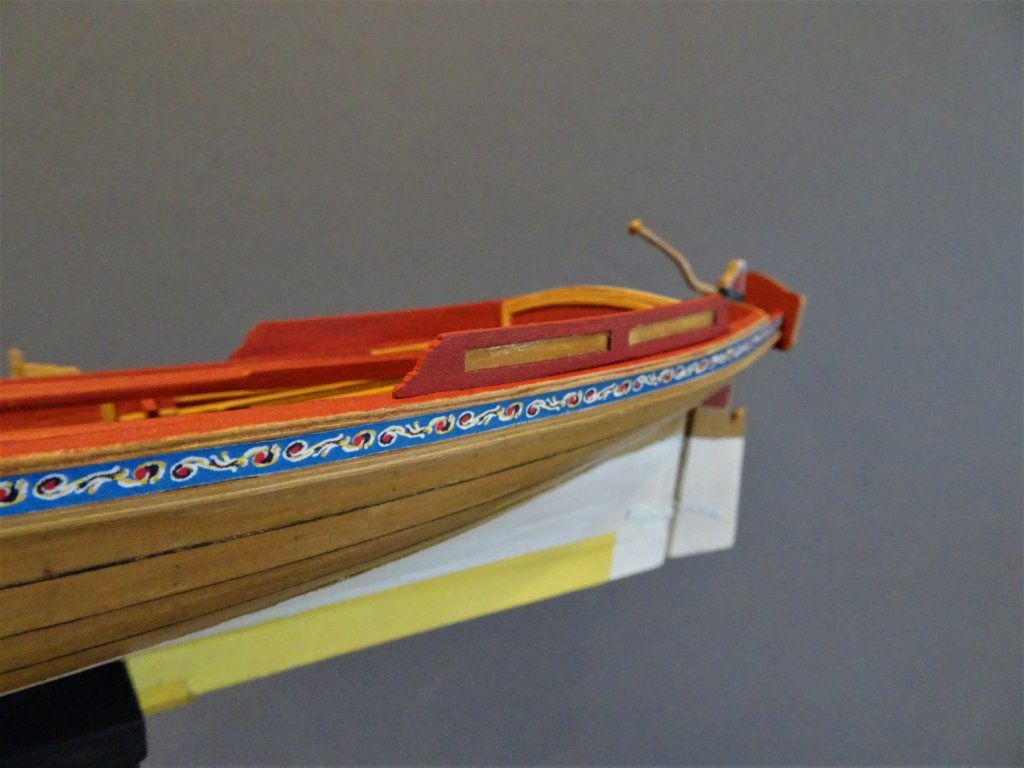
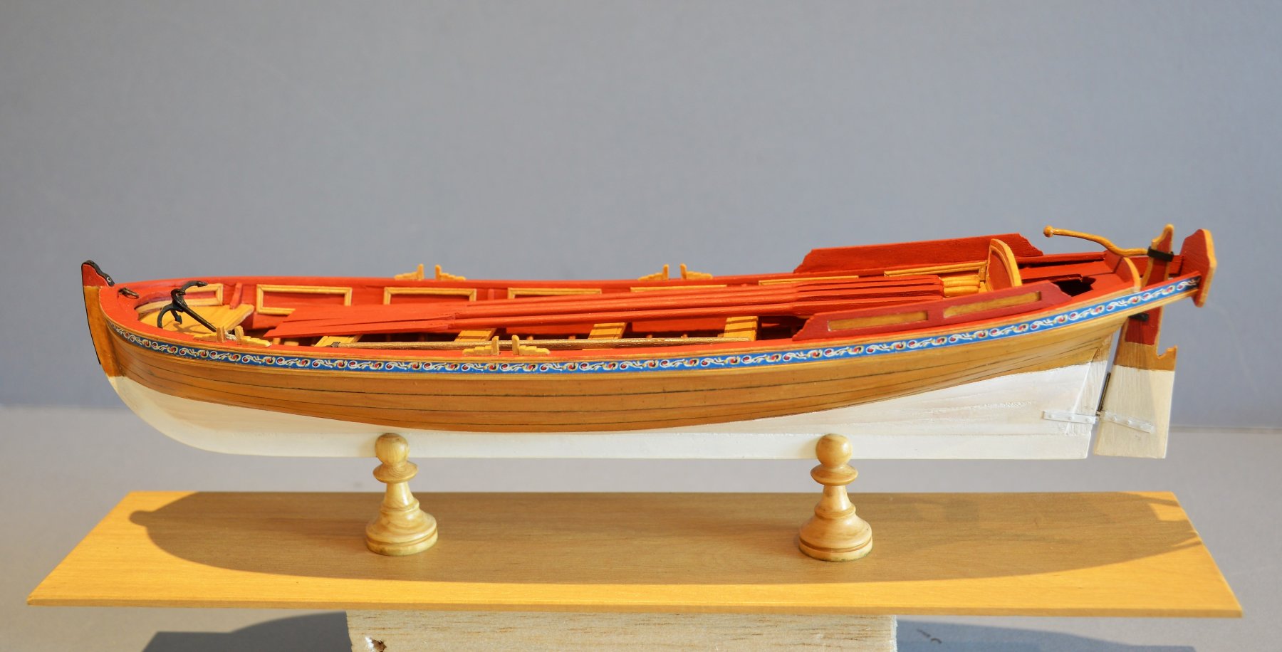
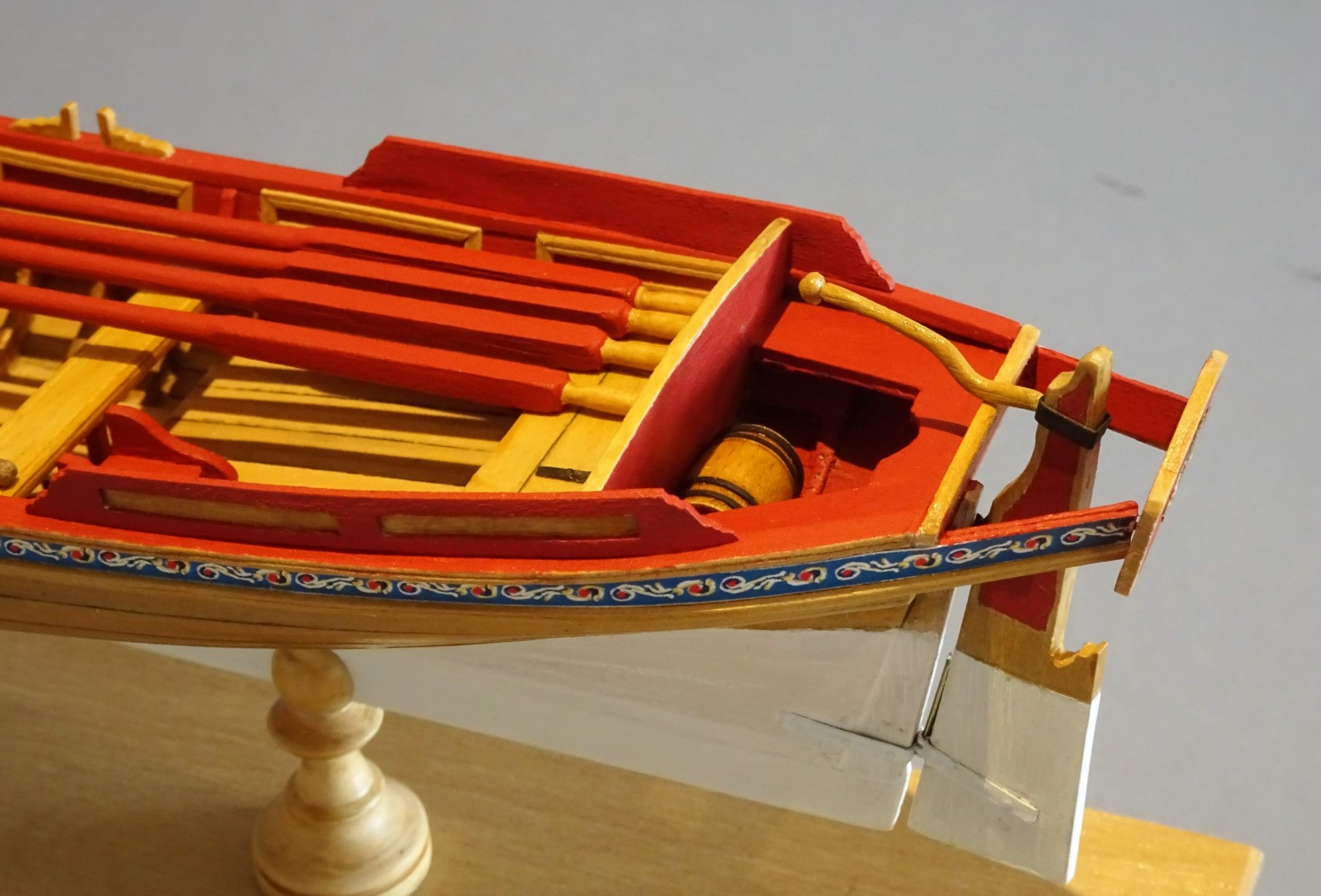
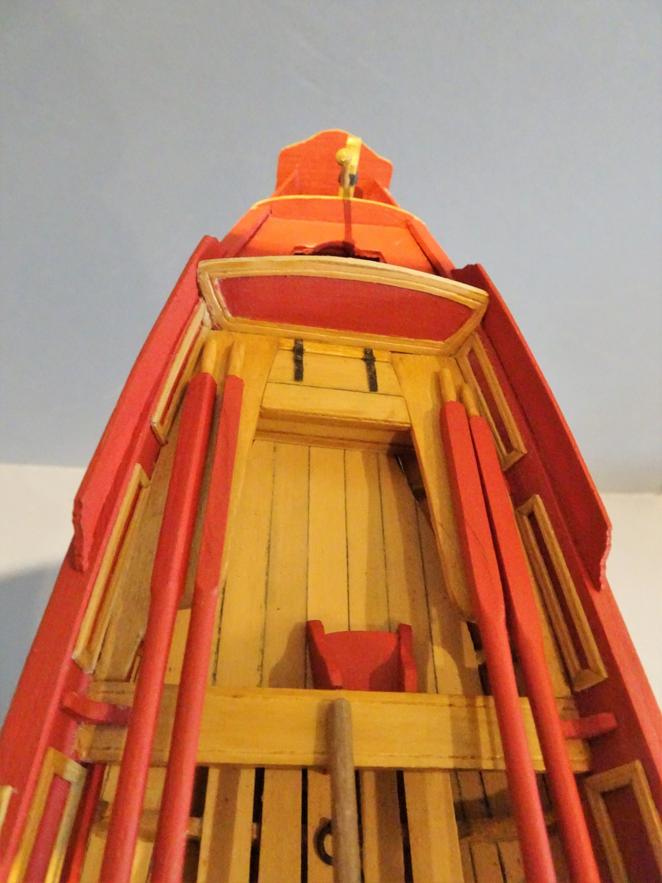
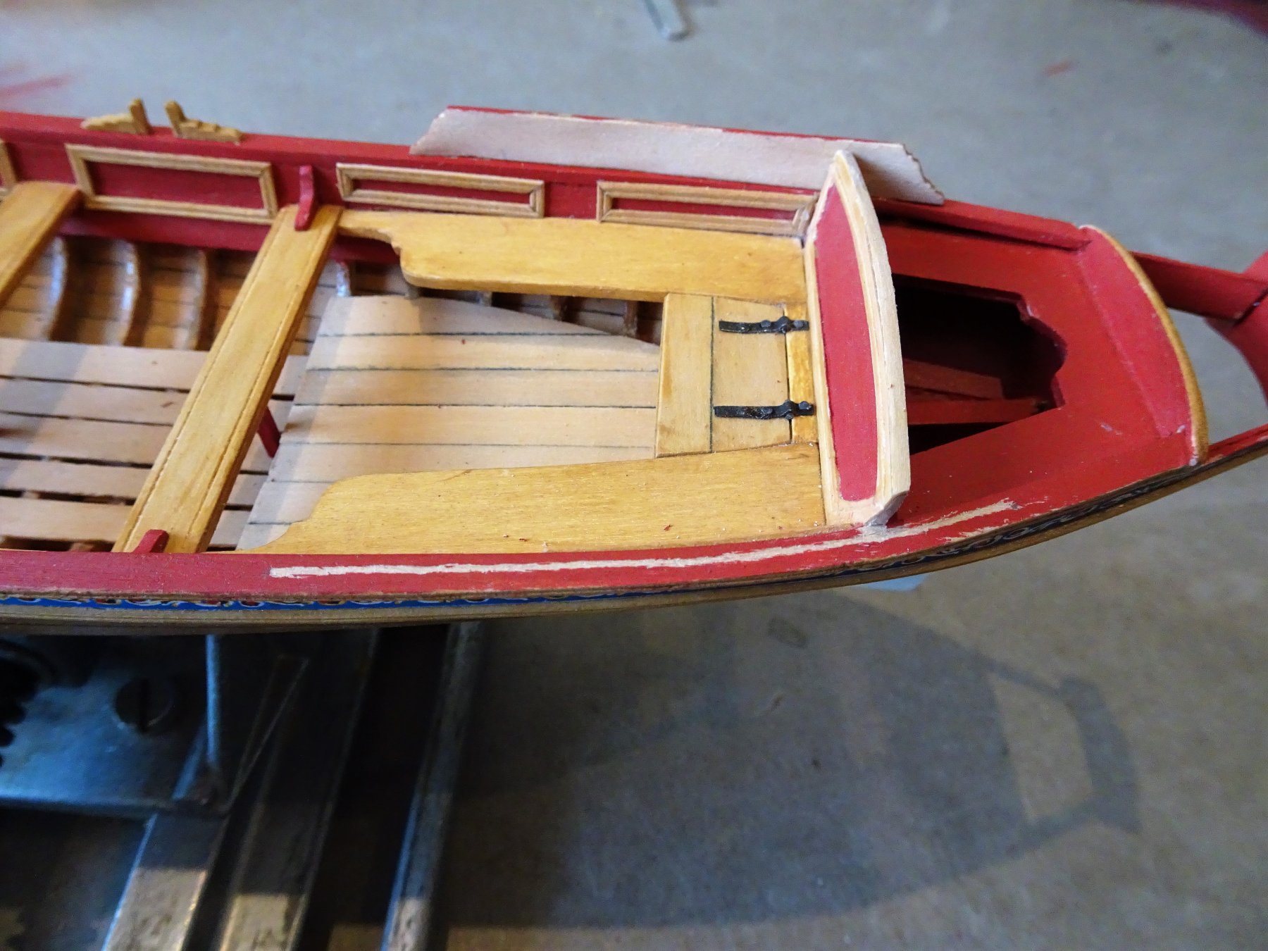
Splashguards I toyed with the idea of making replacements out of Boxwood, but on reflection I think the kit provided items are just fine, particularly as they are painted. I did some preparatory painting before gluing the two elements together, the panel faces, and inner moulding edges. The guards were then sanded down to around 0.9mm in thickness. Before fitting, the seat back needed some very careful paring back using a scalpel and light sanding. I also needed to shape down the backrest top to fall just below the splashguard top edges. This all needs to be done with soft hands and by fine degrees, any slips at this point could prove problematic in restoration. The guards require the water /heat treatment to impart some curve to follow the line of the rail. This is another exercise that requires some care. It was good to have a spare unit in the kit as I did break one. I was a little concerned that the water would weaken the pva, but immersion was only for a few seconds before pegging around a jar top to apply the heat. On my Pinnace at least, two curves were required, a short one where the guard passed around the seat back, and a more gentle curve forward. 0968 Forming the aft curve. 0970 and the forward curve. Getting the curve right is necessary for the guard to sit on the rail without tension, otherwise gluing it will be a difficult task. 0974 Once I was happy with the fit I painted the exterior face of the guard. 0975 To get a good grip it was necessary to scrape a paint free line along the top of the rail. This was carefully done with a scalpel point. 0981 The actual fitting of the guards was problem free with quick grab using full strength pva. The inside faces of the guards were painted once in place. 0982 0983 0984 So the Pinnace is effectively finished, some fettlin' to do, and a base to make which I don't think will take too long. B.E.


- 156 replies
-
- 19
-
-
- pinnace
- model shipways
- (and 1 more)
-
I was checking this out when Dave beat me to it, the Caldercraft guns barrels and carriages would be a great improvement on the Amati offering. When searching for replacement items I tend to look at the scale actual size and match that to what's available regardless of scale. A small gun at 1:64 may well serve as a larger one at 1:72. I would talk directly to Jotika, ask them what the actual size of the guns at 12 and 24 Ib are. Cheers, B.E.
-
Nice progress Mike, that ebony finish is going to look great . I too would take the higher copper line, and as for getting the Verdigris finish I understand urine is the way to go, who was it on MSW who made a great job using this method, having a senior moment, his name has slipped my mind. Personally I quite like the old copper penny look. B.E.
-
Thanks Martin, both Mrs W and William are quite forgiving of my raiding of their respective possessions to serve in the shipyard. Both Amati and Mantua do a range of period figures for 1:64 scale at around 25mm high. Artesania do a range of 27mm figures one of which I used to represent the ill fated Captain; Cmdr John Hamilton Gore on my Pegasus. In the UK I use either Cornwall Model Boats, or the Model Dockyard, (both in Cornwall) but my 1:24 scale Pinnace figure I purchased from Dean's Marine. Regards, B.E.
- 156 replies
-
- 2
-
-
- pinnace
- model shipways
- (and 1 more)
-
I wish Thomas, no he was a modified bought figure (see my reply to Nils above.) Regards, B.E.
- 156 replies
-
- 2
-
-
- pinnace
- model shipways
- (and 1 more)
-
I don't recognise that as a feature of English gun carriages particularly in the era of your build. Amati are notorious for providing otherwise good kits with generic out of scale fittings, are the gun carriages made of metal? I seem to recall that they supplied their Fly kit with such items, and gun barrels even fitted with dolphins. at one point. The Amati guns provided with my Pegasus kit looked superficially ok, but they were seriously over scale, and not of a correct profile, particularly around the muzzle, and with the bore of a siege gun. By the late 1790's most inboard works were painted yellow; although Red Ochre was still the official colour many Captains requested Yellow, and were in the habit of having their gun carriages re-painted. Not until 1807 did the Navy Board formalise the procedure by notifying Dockyards to accede to Captains requests for a yellow scheme. Vanguard was first commissioned in 1790 and had some re-fits before she fought at The Nile in 1798, by which time she may well have had the yellow scheme, she was the Flagship of Nelson at the battle. Even so I think there is sufficient leeway to give her the Red scheme if you prefer that. B.E.
-
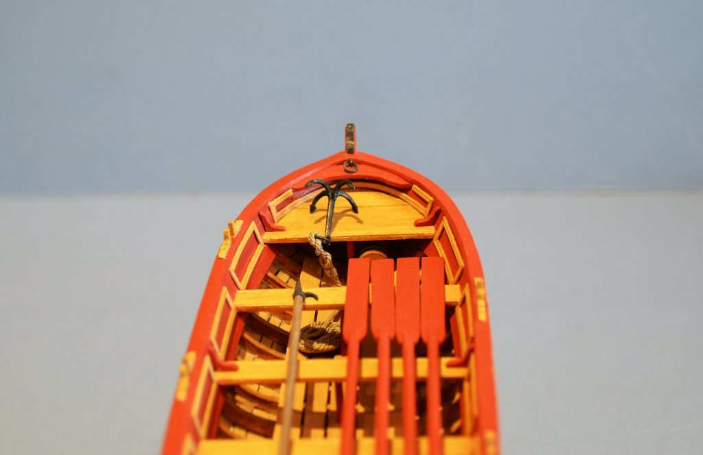
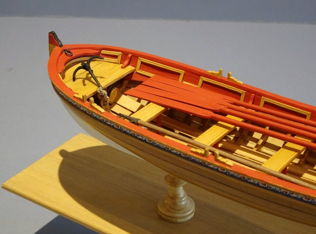
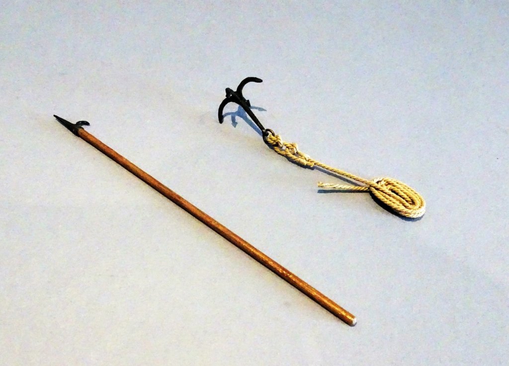
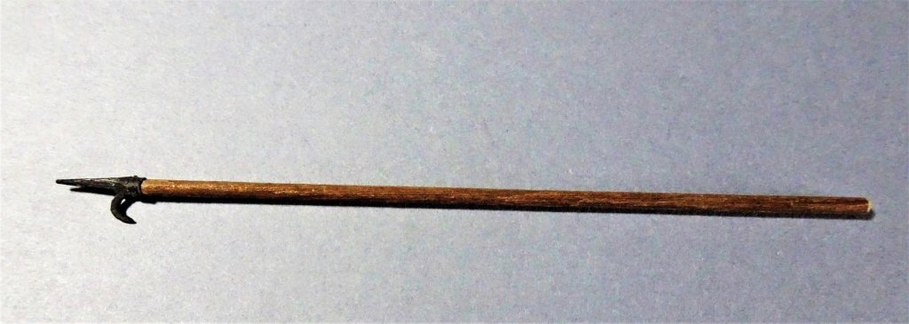
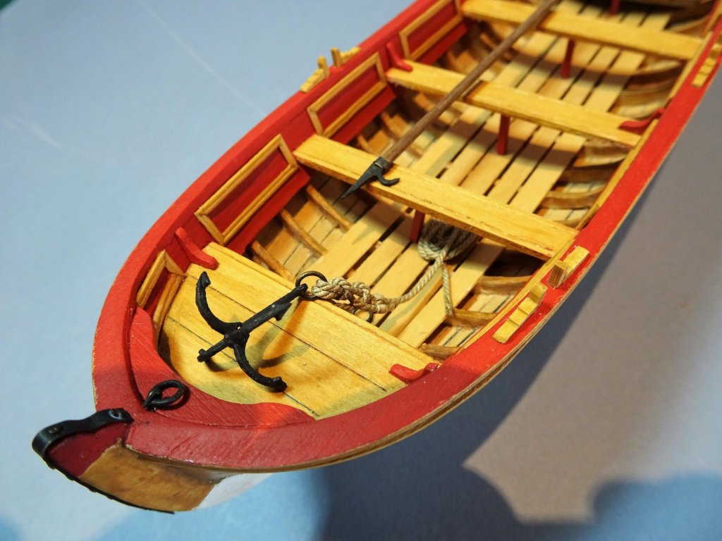
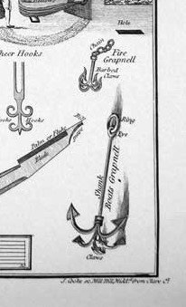
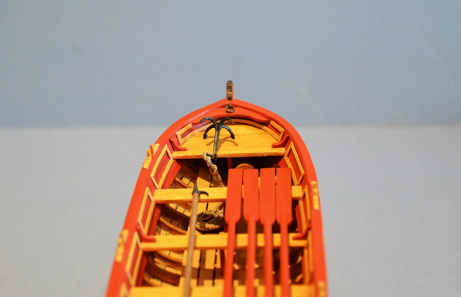
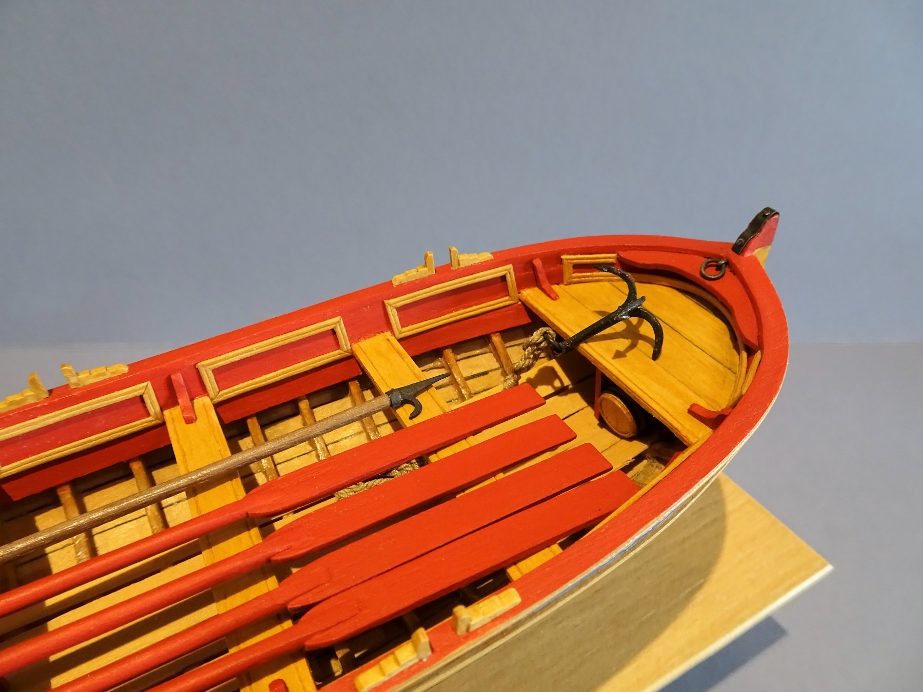
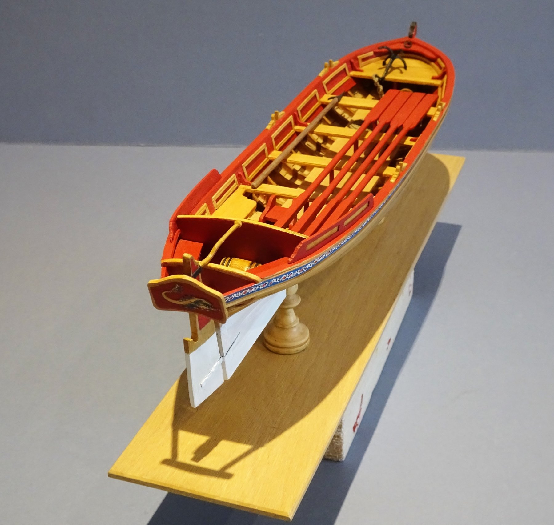
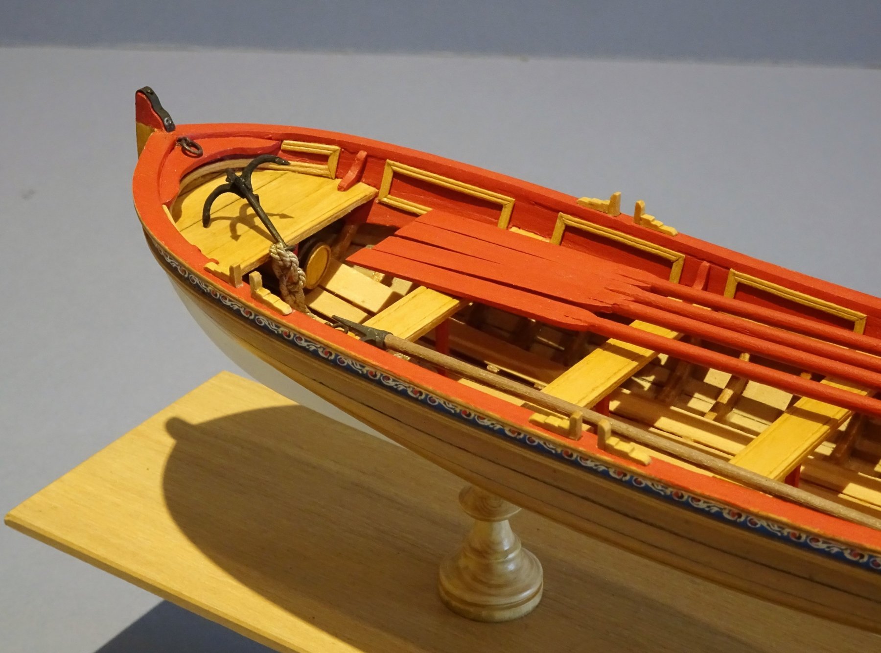
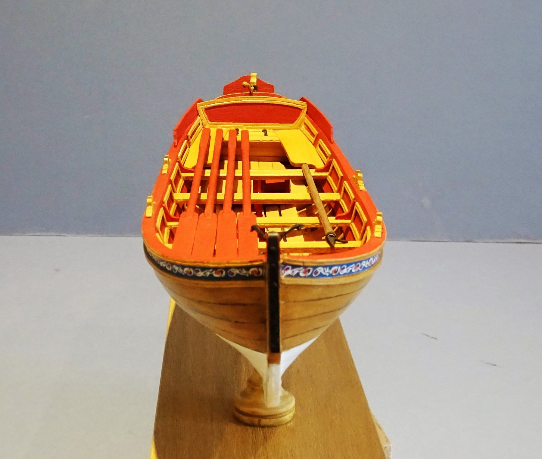
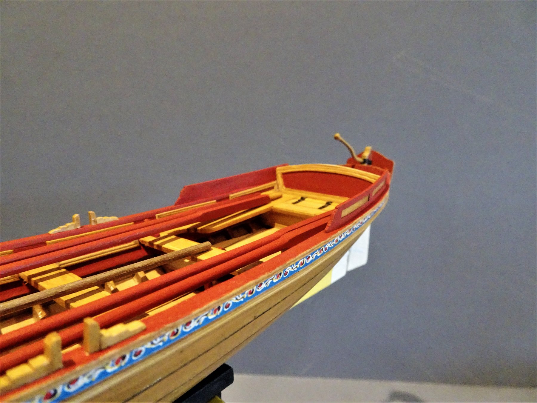
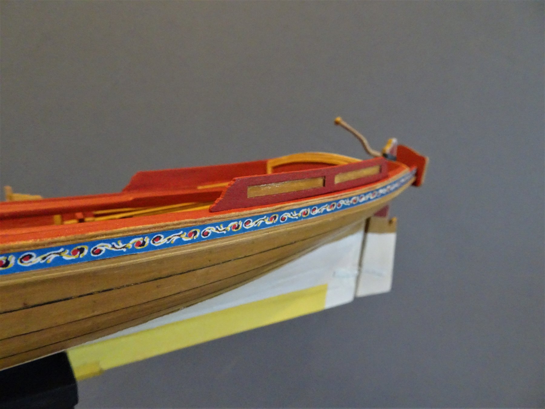
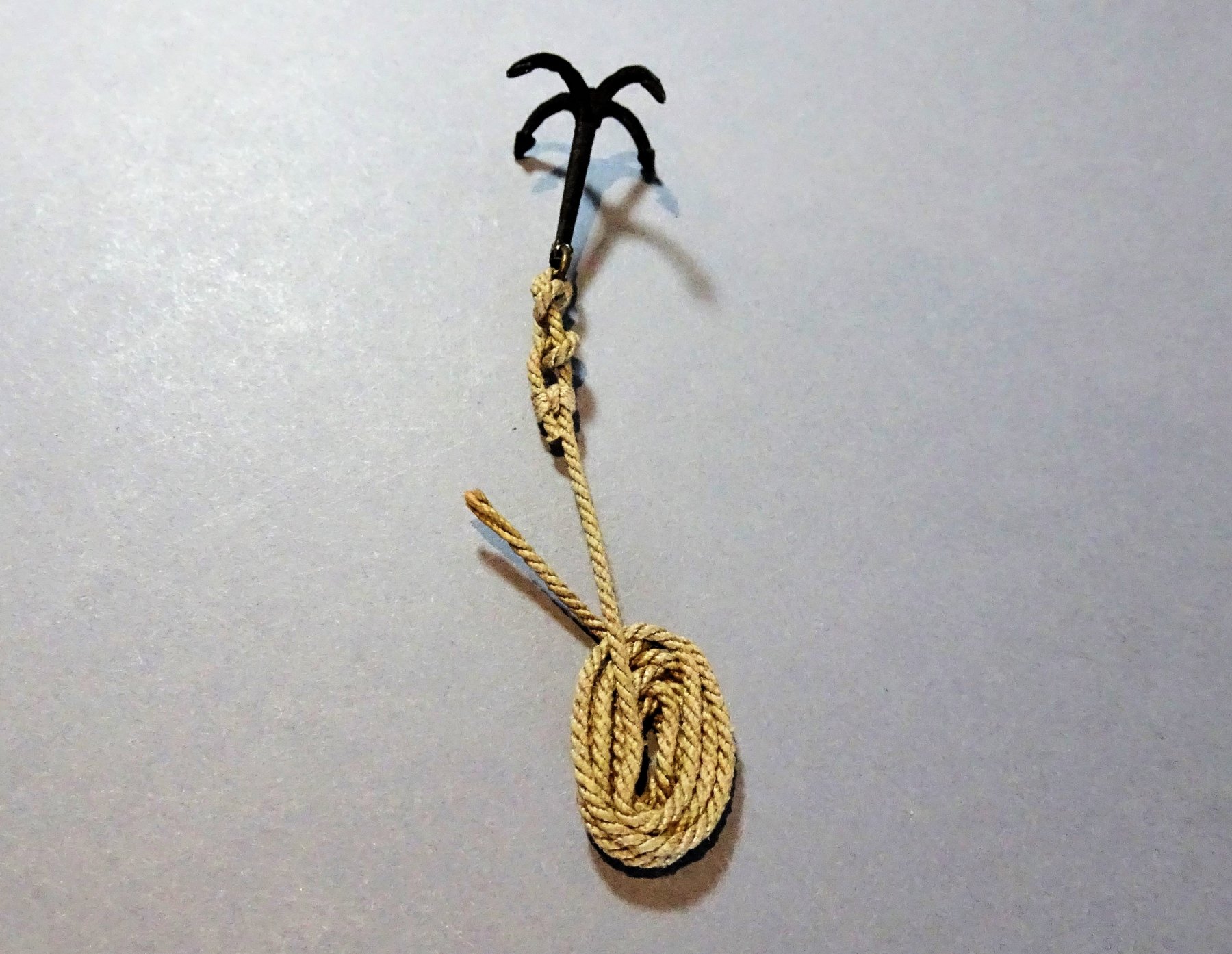
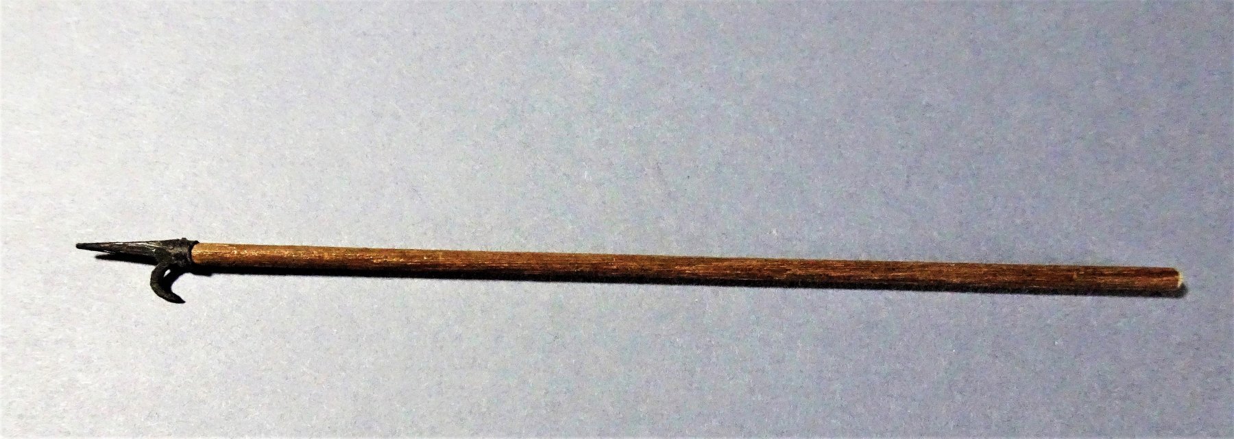
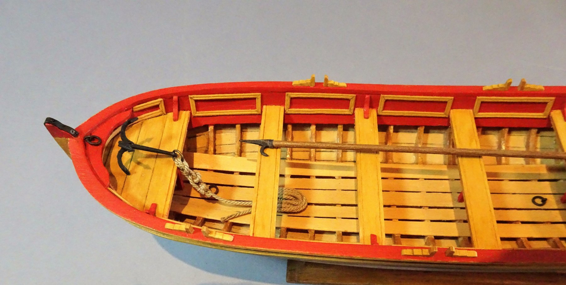
A small diversion to play with the boat equipment. The Grapnel The grapnel as provided by the kit seems to have been rigged without the benefit of a ring, the line secured directly thro' the eye in the shank where the ring should be. A grapnel as illustrated by Steel shows a ring fitted thro' the eye. Steel gives a grapnel rope circ for ships boats as 3" - 3½" which equates to around 1mm diameter line at scale. 0946 This alone would not be possible without a ring, particularly as the classic hitch for small anchors is a Fisherman's Bend where the line passes twice thro' the ring. He also gives 35 fathoms as the length of the grapnel rope. which scales to 2667mm. This is 8.75ft at scale, where would all that fit in the boat! 0967(2) I satisfied myself with a rope length of around 30' - 300mm which I figured would be long enough for what is essentially a harbour boat. Boat Hook This is shown on the plan but the makings are not included with the kit. 0950 Not too difficult an item to reproduce, I use a soft white metal strip (the arm from one of Mrs W's hair clips, cut and shaped with files, and inserted into a length of thin Walnut dowel. 0948 0964 0956 The Thole pins and chocks are also shown on these shots. Nothing much to say about the tholes except they are fiddly little things to make, parts very small, fingers too big. I changed the style slightly from the plans, and left them unpainted as a contrast to the predominantly red scheme. 0961 Just the Splashguards left to do now. B.E.


.thumb.JPG.38d3a8328c45b266293644fe6f30c99c.JPG)
- 156 replies
-
- 20
-
-
- pinnace
- model shipways
- (and 1 more)
-
Thank you Sailor and Nils. @ Nils - George is a Dean's Marine 1.24 scale figure, but he underwent some serious surgery. originally he was a Vietnam War period American soldier in Jungle gear. His arms were broken in two places, his uniform and jungle hat cut away and he was given some clothes from the slop chest. I was pleased that at a given 1:24 scale he fitted the boat spot on. B.E.
- 156 replies
-
- 3
-
-
- pinnace
- model shipways
- (and 1 more)
-
A beautiful model Chuck, and a fine unique kit, I too will be looking forward to ordering one. B.E.
- 269 replies
-
- 7
-
-
- Queen Anne Barge
- Syren Ship Model Company
- (and 1 more)
-
Thanks Jason, when you start to look the subject of oars you find there is a huge amount of info out there, including many forums on every aspect from making to using, designing and purpose. From what I've read I think you are right that the thicker part of the oar whether it be round or square is primarily to provide balance and improve handling. One reference I looked at said that the square part begins just inside of the pivot point, so perhaps the Pinnace set up is not that far out. B.E.
- 156 replies
-
- 2
-
-
- pinnace
- model shipways
- (and 1 more)
-
This has been a fabulous project to follow Nils, many congratulations on completion on yet another wonderful model. Love your growing museum collection B.E.
- 2,625 replies
-
- 4
-
-
- kaiser wilhelm der grosse
- passenger steamer
- (and 1 more)
-
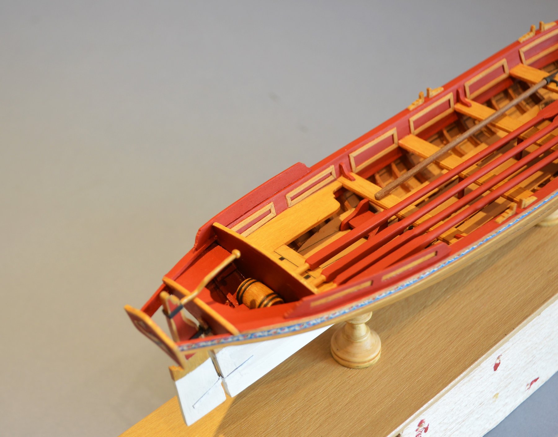
Thank you Steve, Mark and Martin. @ Mark and Martin - With a single banked arrangement the rower should be close to the opposite side to the tholes, to gain maximum leverage. Here's a modern version of single banked rowing and you can see the rowers are close to the sides. These modern oars don't seem to have the old style looms but rather a slightly thickened and protected area where the oar passes thro' the oarlocks, although in this case not all the oars are set the same. Not sure Martin that the extension outboard of the oar should change with the forward/backward movement of the rower, but I base this purely on my very limited experience of having an occasional scull up the river. Cheers Guys, B.E.
.thumb.jpg.9982c2a3cf001f6c35eba8eba2c486a8.jpg)
- 156 replies
-
- 8
-
-
- pinnace
- model shipways
- (and 1 more)


.JPG.090a2c0221b6a05ee7b8ccc880f4a50c.JPG)


.JPG.ef53584232662b8fb1ce2db9e855d49a.JPG)
.jpg.f134bd5969be299ecaf8de42c03df869.jpg)