.JPG.ca33079f5815b861e67b9c2cccd37982.JPG)

Blue Ensign
-
Posts
4,567 -
Joined
-
Last visited
Content Type
Profiles
Forums
Gallery
Events
Everything posted by Blue Ensign
-
 Thanks mobbsie, I finally got over my indecision and opted for the red stern sheets, but plain thwarts. The oars will be painted red overall, and I felt it better to have a contrast across the thwarts. I'm warming to this little boat the more I get into the detail, and previous niggles fade into the background. B.E.
- 91 replies
-
- 2
-

-
- 18th century longboat
- model shipways
- (and 1 more)
-
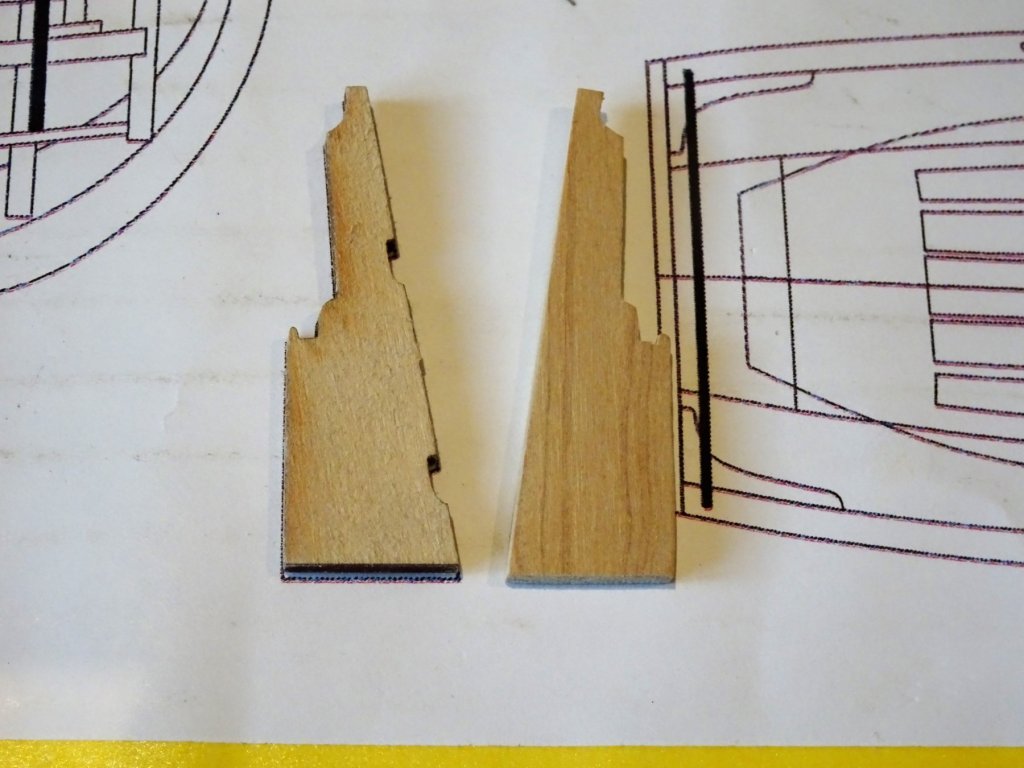
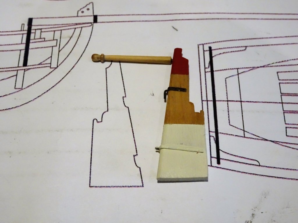
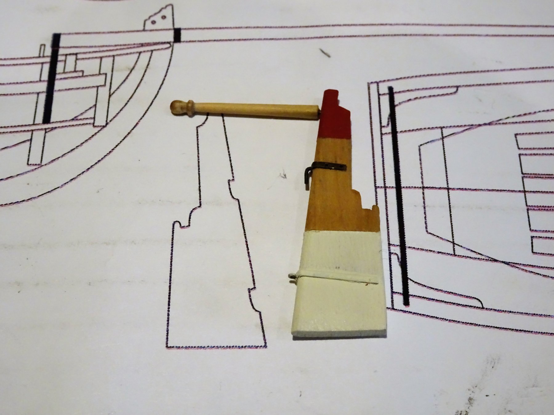
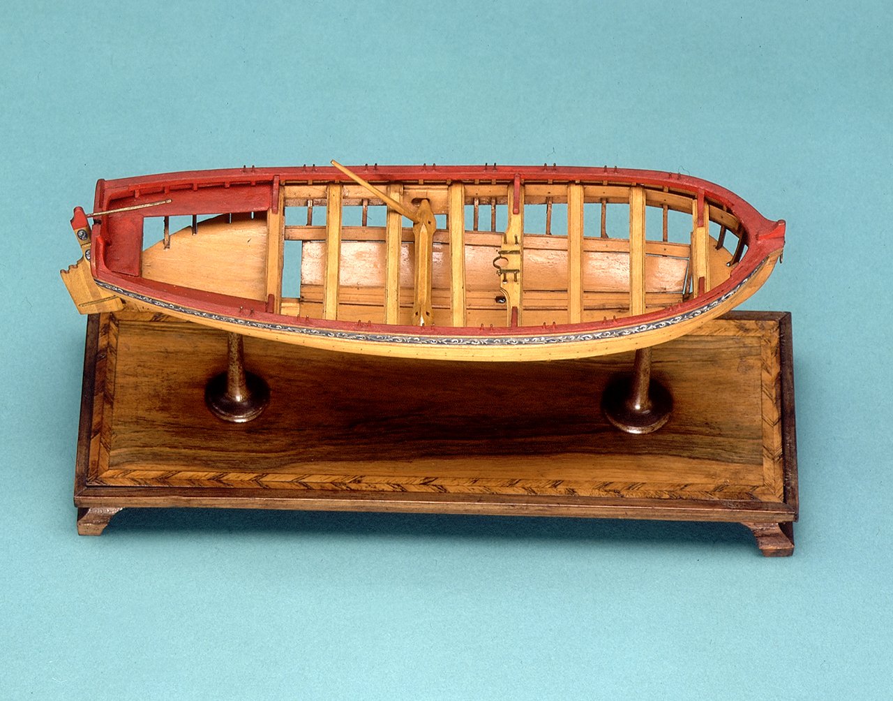
Building the Rudder As with the Pinnace model I have deviated from the kit arrangement for hanging the rudder. As can be seen on the NMM model of the Medway Longboat, there are no cut outs in the rudder to take the pintles. Lavery (Arming and Fitting) comments on this different approach to hanging the rudder on ships boats: The rudder was hung on the sternpost by only two gudgeons and pintles. Unlike the rudder on a ship it was likely to be hung and unhung every time the boat was used and it needed to be easily removeable. The lower pintle was fitted to the sternpost rather than the rudder. It was very long and extended almost up to the waterline. The upper one was shorter and fitted to the rudder. 1898 A Boxwood replacement was made. The fiddly bit with rudders is adding the straps for the gudgeons and pintles. 1959 I used thin brass strip chemically blackened for the straps indents were drilled into the surface to give a slight impression of nail heads. Tape was used to guide the angles of the straps. The process of attaching the straps inevitably marks the paintwork as can be seen in this photo. 1964 The completed rudder. Work yet to do on the tiller, needs fining down some. 1969 1973 Moving back inboard now. B.E.

- 91 replies
-
- 14
-
-
- 18th century longboat
- model shipways
- (and 1 more)
-
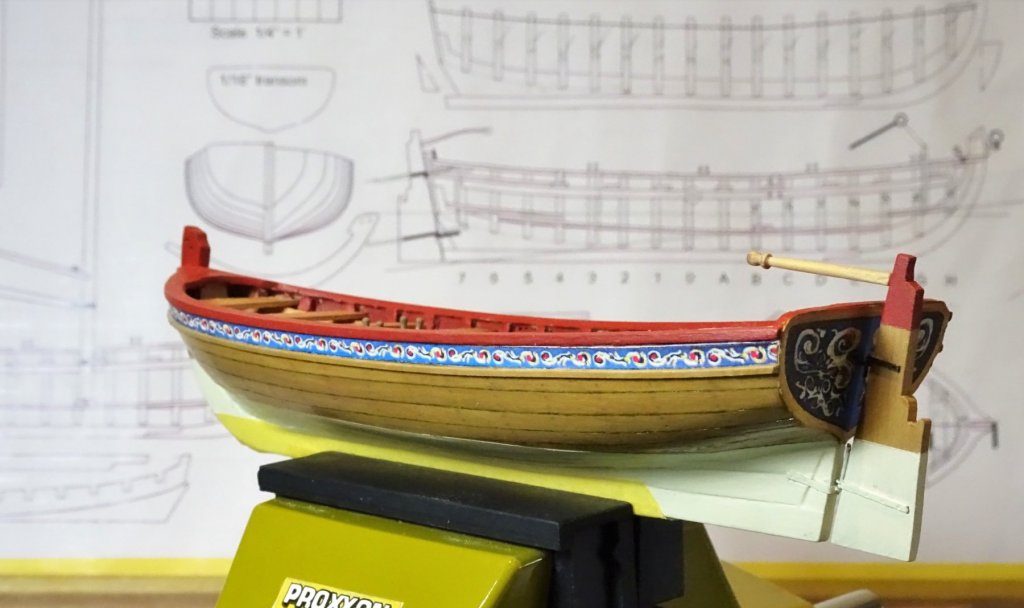
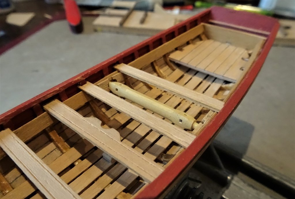
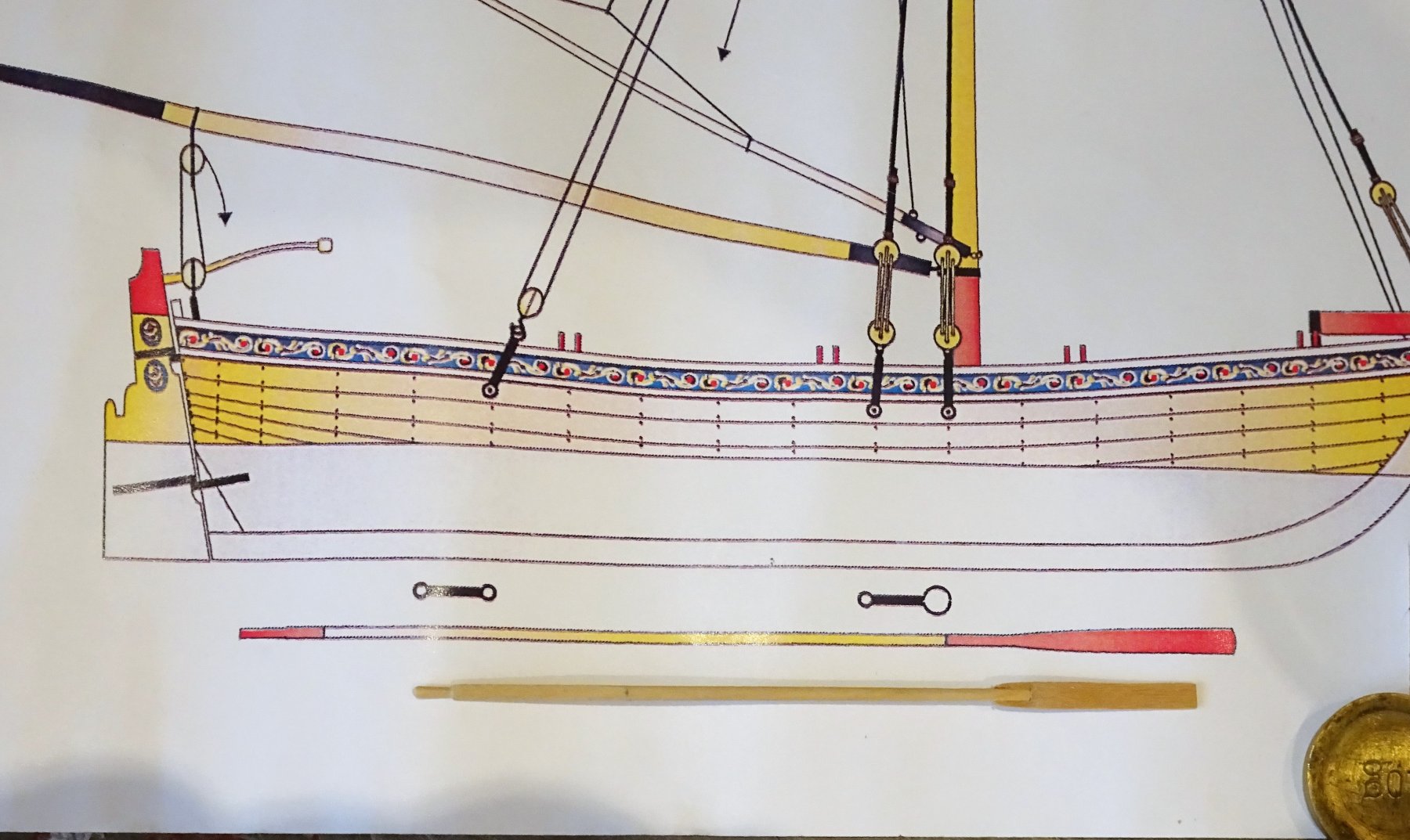
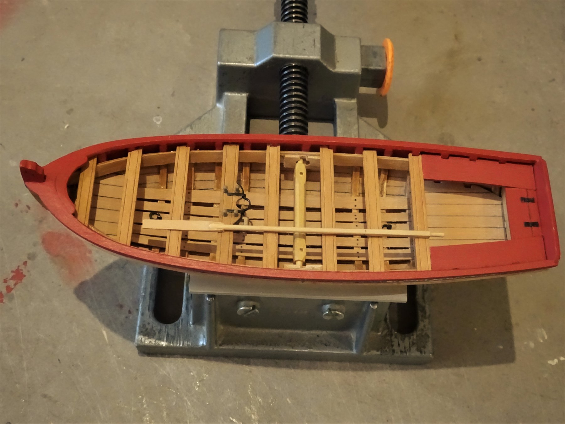
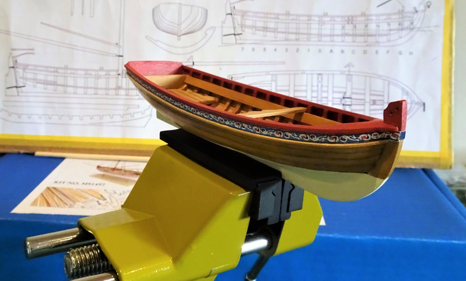
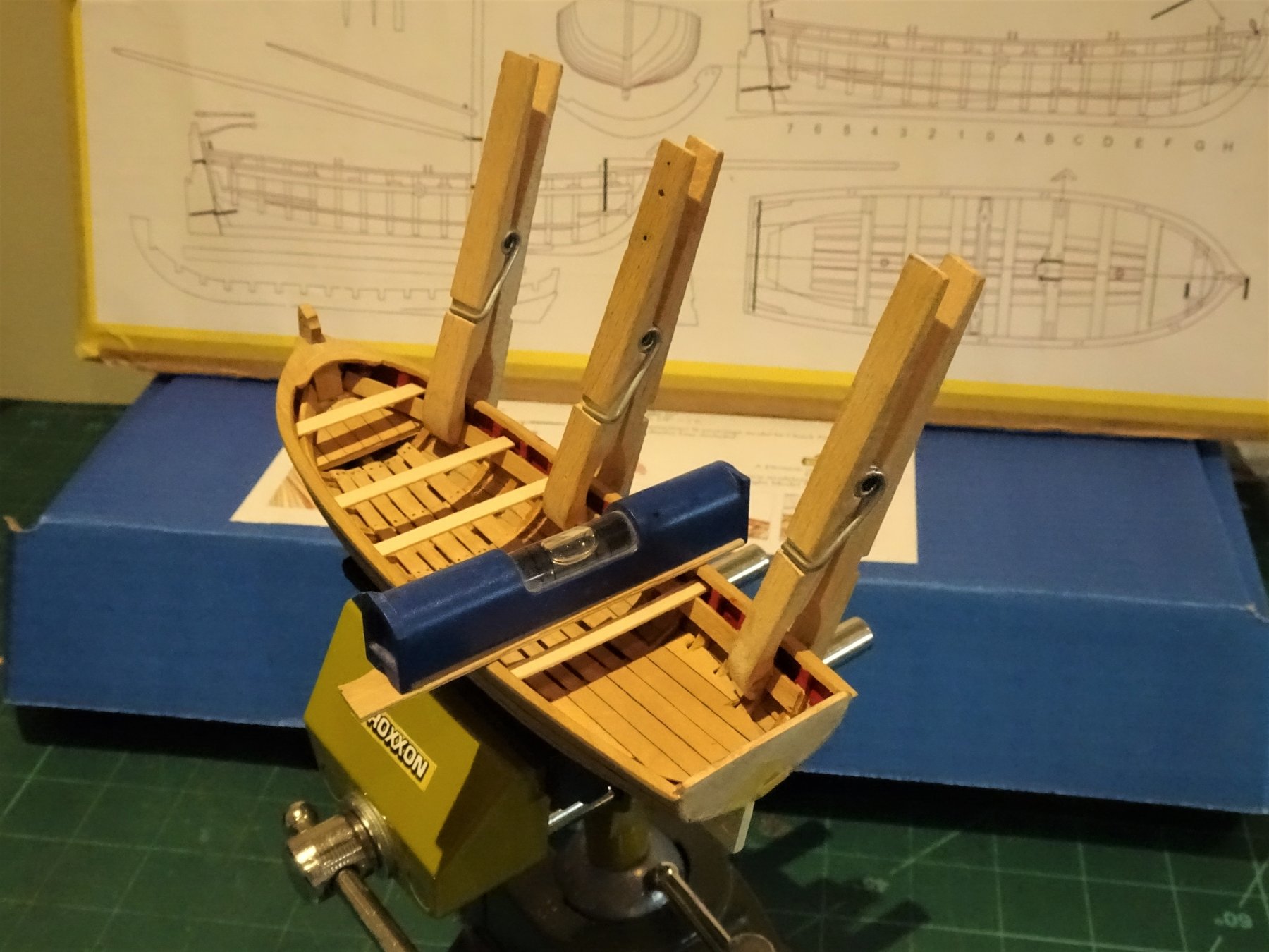
Thanks Al and Steve; always a good idea to re-do stuff Al if it bothers you, otherwise it will catch your eye and niggle away forever. The thwarts are now fixed and some of the 'iron work' completed. Decided to take a short break from progressing the boat to consider..... The question of oars Chuck has fitted out the Longboat as single banked, but my preference is towards a double banked arrangement. I mention this because it will have a direct bearing on the length of the oars. The kit provided oars are 125mm in length which scale to an overall length of 19'6" With a double banked arrangement the oars are obviously shorter as they don't have to cross the boat to the Thole on the opposite side. There is a formula for this: Divide the span by 2, and then add 2 to this number. The result is called the “inboard loom length” of the oar. Multiply the loom length by 25, and then divide that number by 7. The result is the proper oar length in inches. Our Longboat model has a breadth of 51mm which scales to a breadth between the tholes (the span) of 96.37"; applying the formula the length of 179.24" is given (14.9') - at 1:48 scale = 94.8mm. Using Steel I calculated the requirements for the sections of the oar. Section L scale equiv Thickness Handle 10" 5.29mm 0.85mm Ø Loom 39" 20.63mm Thick: 1.45mm Depth: 1.72mm Body 84" 44.45mm Blade 48" 25.40mm Breadth. Inner end: 0.73mm Outer end: 2.91mm Thickness Inner end: 1.20mm outer end: 0.26mm . Square section 1.80mm Boxwood strip and 4.50mm x 1.25mm strip for the blades was used. A prototype is made up using these dimensions. 1904 The difference between the 'Single banked' oar length as per the kit, and the 'Double Banked' length as per the dimensions above can be seen. 1905 The oar length positioned on the boat looks good to my eye and I will make a set to those dimensions. I don't think I will make a full set of 16 oars, maybe six for the purposes of display. B.E.


- 91 replies
-
- 14
-
-
- 18th century longboat
- model shipways
- (and 1 more)
-
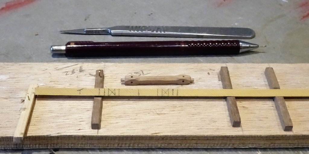
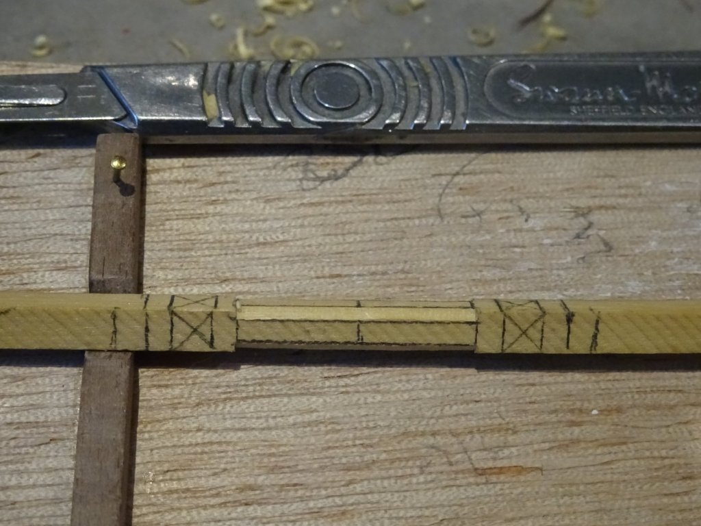
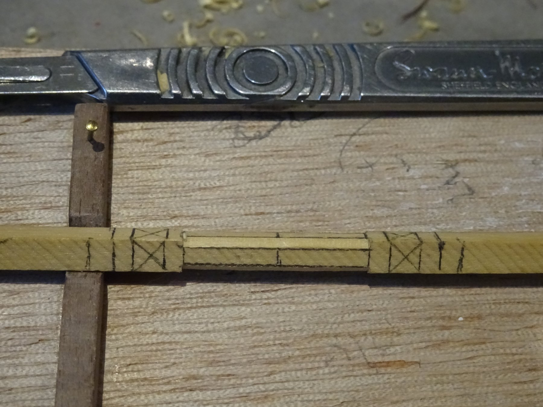
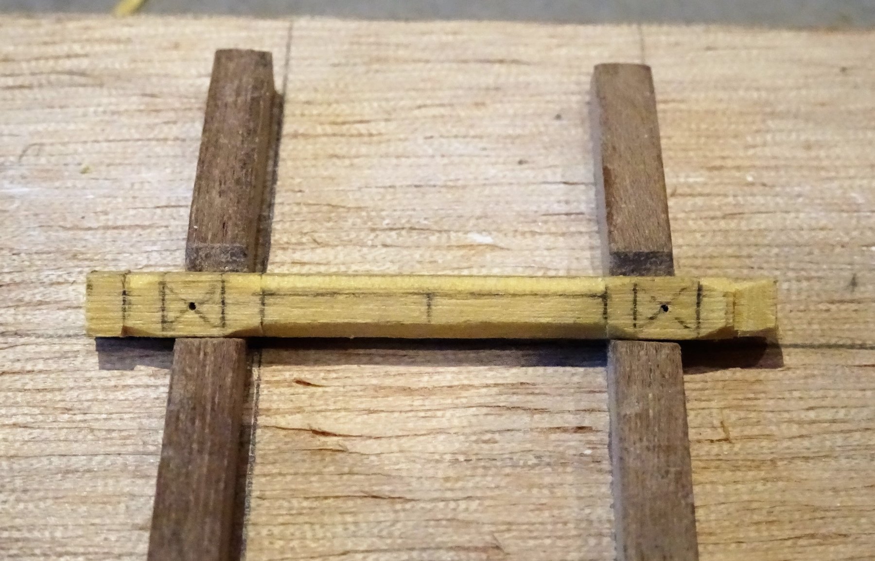
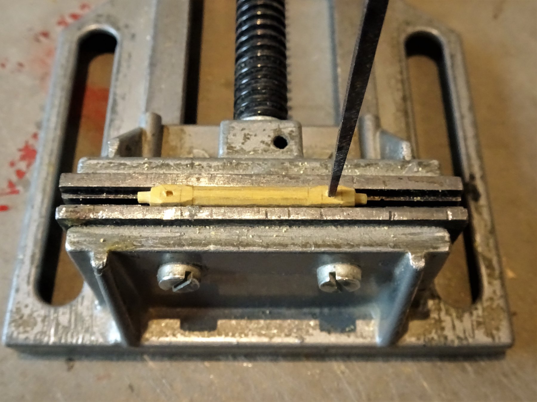
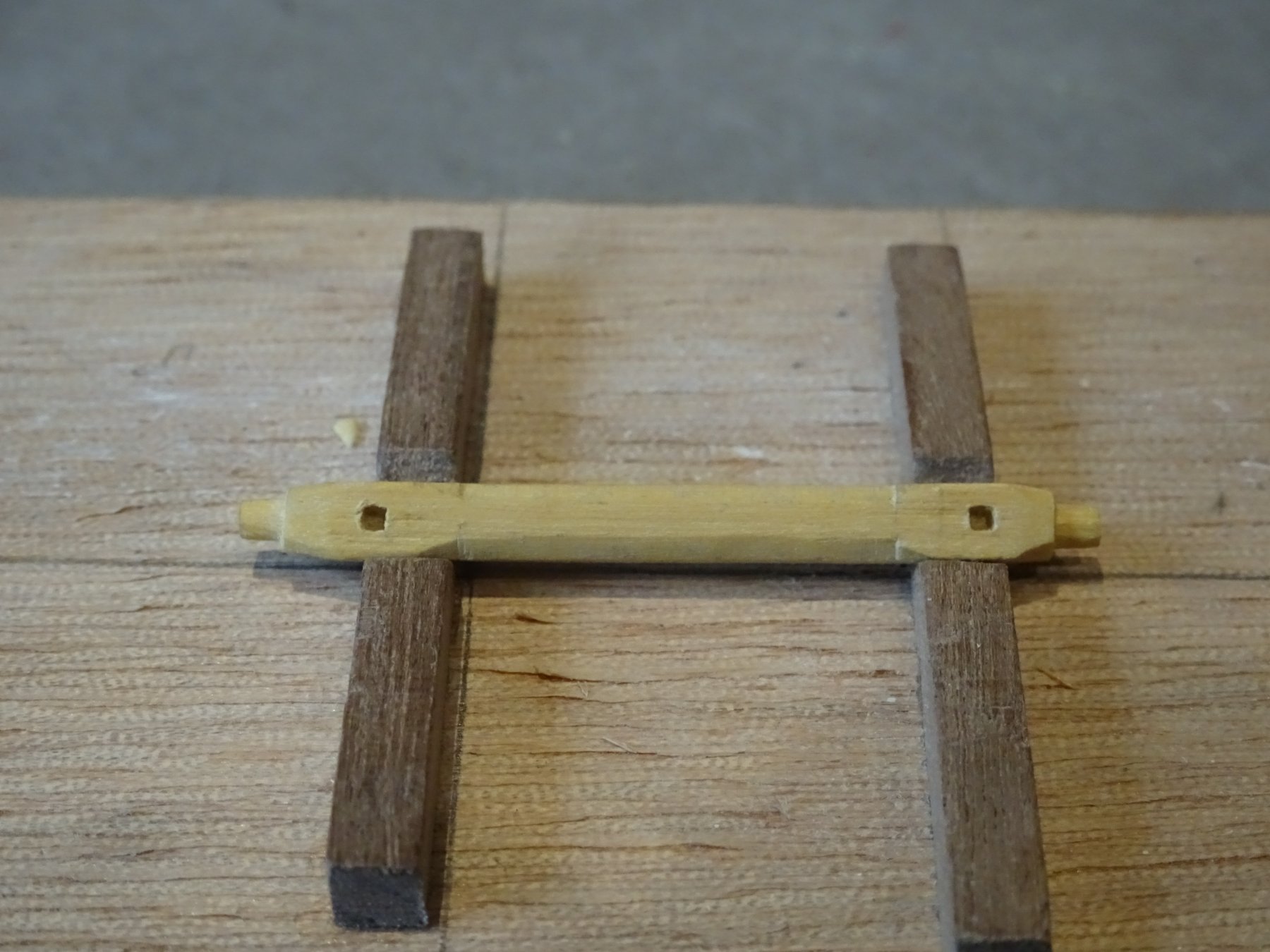
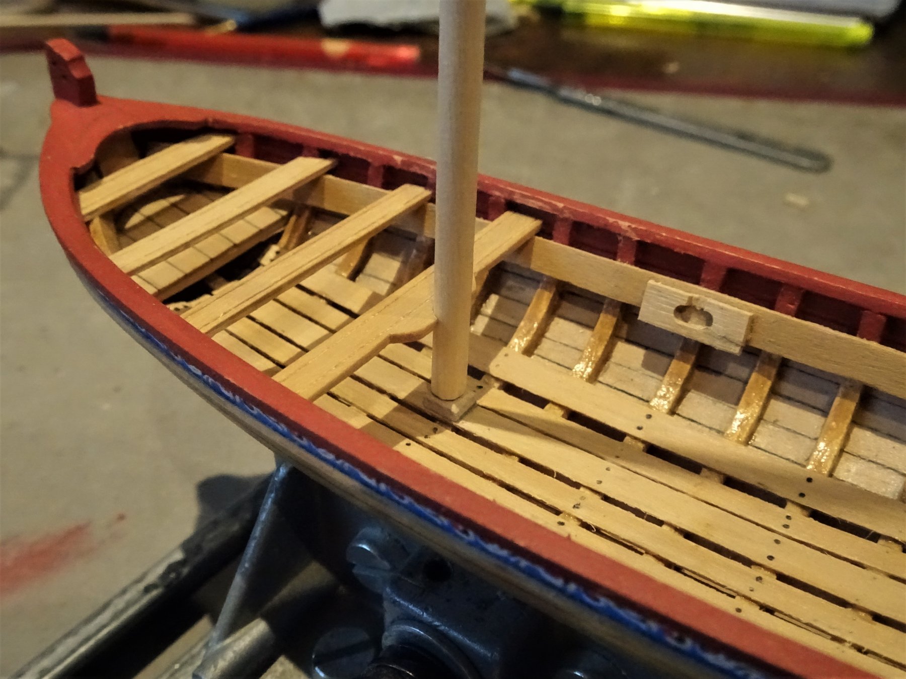
Cheers Guy's, this next post will answer your question re the Windlass holes Jason. Making a Boxwood Windlass The kit instructions don't include any photo's detailing the making of a windlass. This is my approach. 1862 Using 4mm square stock the sections are marked off using my prototype as a guide. 1865 The octagonal center section is formed on a jig last used for mast making on Pegasus. A scalpel is used to carefully shape the section. 1867 Chamfers are formed where the square sections meet the octagonal and end sections. 1871 Beyond the square section the ends are reduced to cylindrical section to form axles which slot into the mounting blocks. This again done using Scalpel and needle files to finish the job. 1870 The end of a square section needle file is used to 'square up' the holes for the windlass bars. A tap with a light hammer forms the square. 1875 Having a vertical slot in the mounting block allows for easy positioning the windlass. A small wooden plug will be added later to secure the windlass. 1876 1880 1883 I can now fix the thwarts and attend to the paintwork and varnishing. B.E.


- 91 replies
-
- 19
-
-
- 18th century longboat
- model shipways
- (and 1 more)
-
Always look forward to progress shots Thomas, I so admire your work. B.E.
-
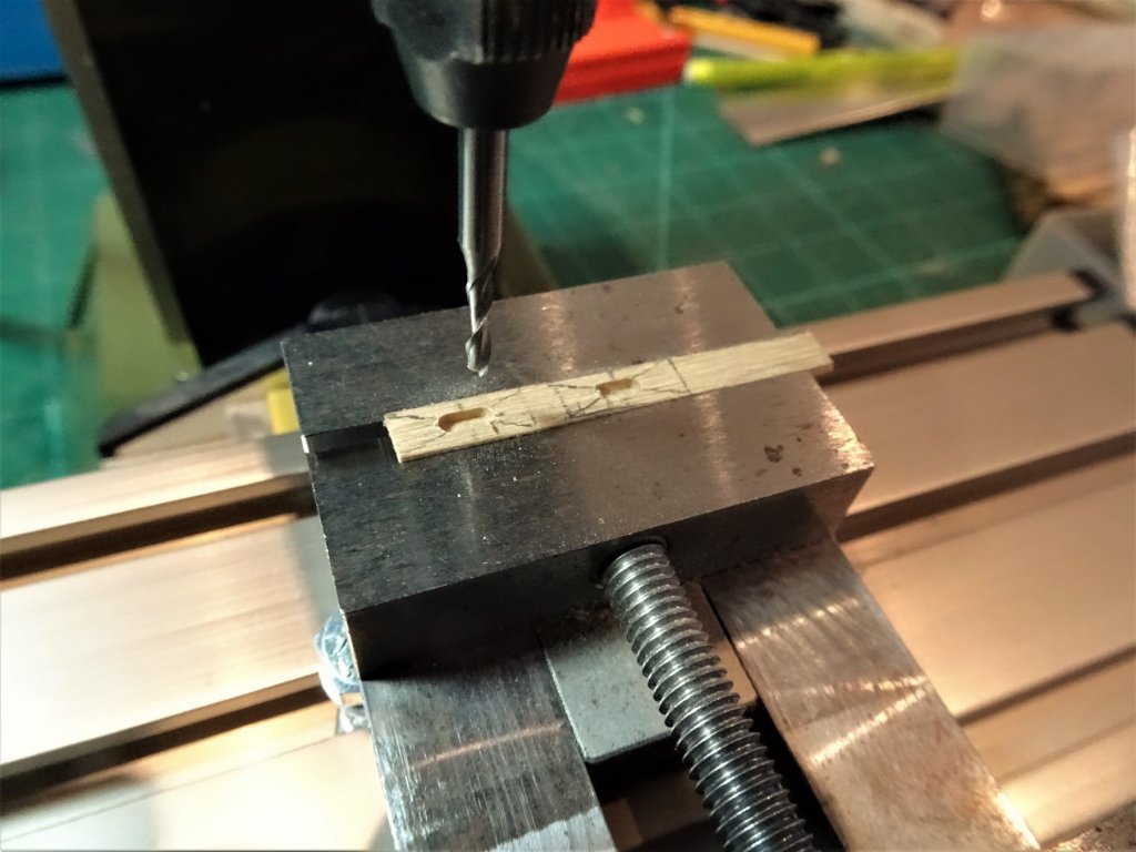
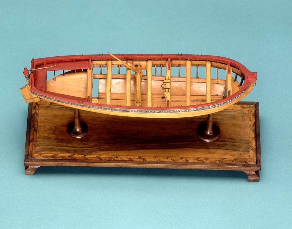
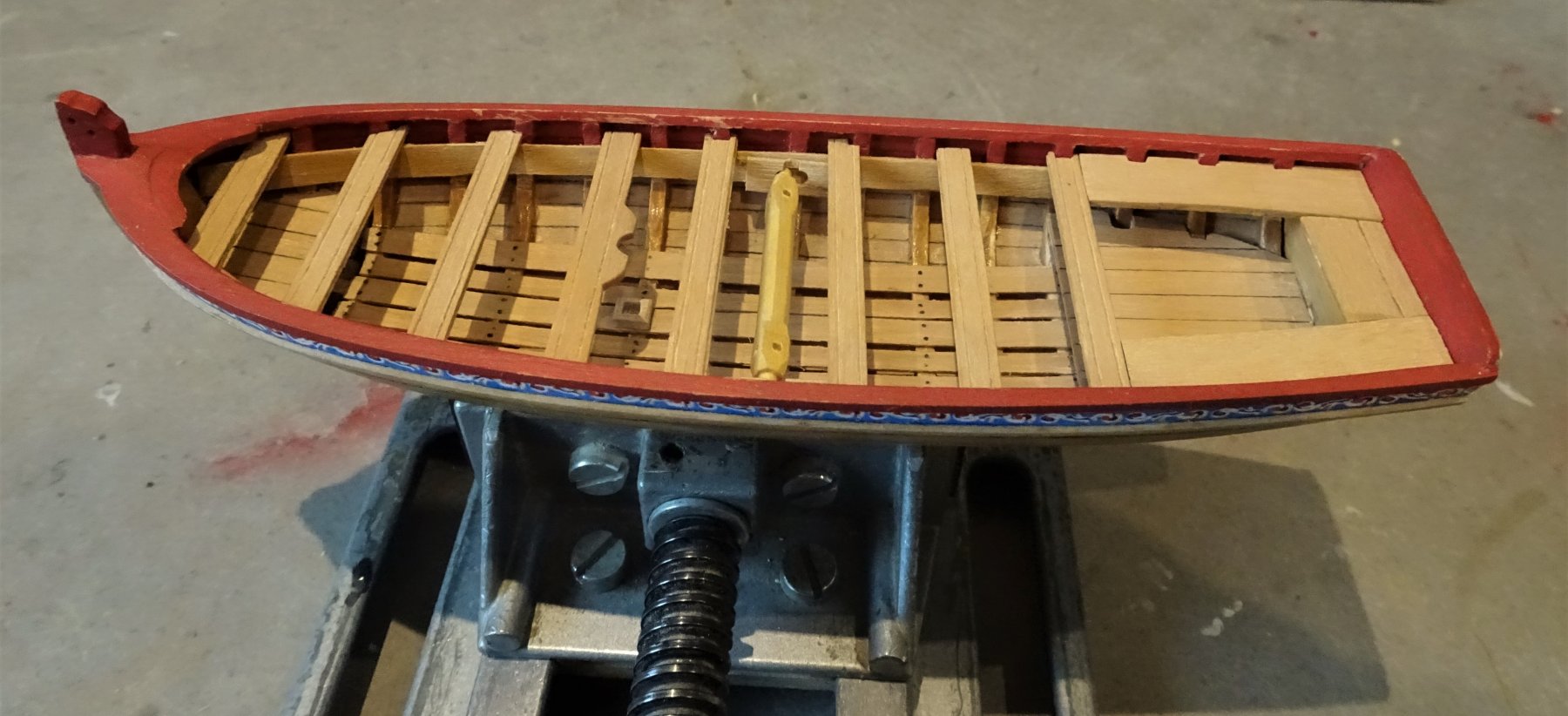
Windlass. I think this is better made and fitted before the thwarts are permanently fixed, more room to work with. NMM model of Medway Longboat 1742. Rather than just stick a pin in the end of the Windlass and engage it in a hole in the Risings I followed the arrangement of a reinforced slotted block as shown on the NMM versions. (see above) 1807 Windlass blocks being formed on the Mill. 1820 I firstly had to get the overall length of the Windlass as it would fit into the blocks before I went to the trouble of shaping the real thing. This was very much a trial and error exercise. In practice my Windlass worked out at 42mm o/a length as compared to the plan indicated length of 47mm. The difference is accounted for by the thickness of the risings/reinforced mounting blocks and the inward curve of the hull. 1815 Using some 4mm square stock I firstly made a windlass of Beechwood to practice my technique and fix the proper dimensions before I moved onto my precious Boxwood stock. Beech is easy to carve, and is far better than Limewood at holding definition. 1816 So far so good, onto the proper version. B.E.

- 91 replies
-
- 16
-
-
- 18th century longboat
- model shipways
- (and 1 more)
-
I agree with the comments above, as an overseas customer I would prefer to have the complete set rather than have to order them separately at a later date. Regards, B.E.
- 269 replies
-
- 7
-
-
- Queen Anne Barge
- Syren Ship Model Company
- (and 1 more)
-
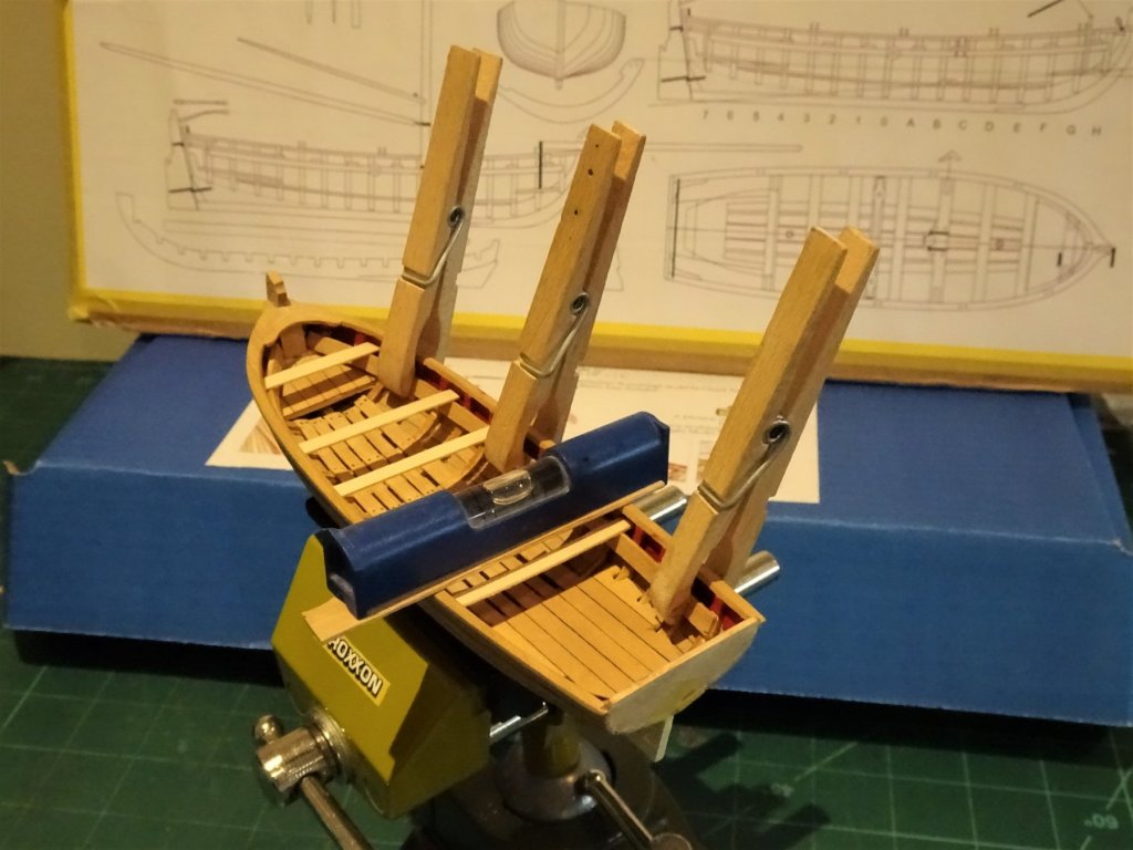
Thanks mobbsie, had a couple of good days but came back before Storm Brian came in. Didn't fancy 17miles of road works and narrow lanes on the M6 in bad weather. Thwarts n'all I replaced the soft Limewood strip with Boxwood. In considering the thwart dimensions I would suggest that the kit instructions be ignored as their dimensions are incorrect. Go by the plans and have a look at Chuck's log of his build. The plans show thwart widths of 4.5mm and 6.5mm (for the wider mast thwart) I cut this out of some wider stuff and shaped the central mast support section. 1732 Thwarts trial fitted but not finished. As can be seen in the photo the process has resulted in some scuffing of the paint, but this is only a first coat. 1735 1733 1736 Still pondering whether to paint the stern sheets or leave them varnished, but I have decided to leave the thwarts in their natural state. 1822 Before the thwarts are fitted it is a good time to set the heel chock for the mast. I made mine from a bit of Boxwood stuff with a square cut mortise to take the mast heel. Thwarts one - three from the bow can now be glued in position. I will now leave the fitting of the remaining thwarts until I have made and fitted the Windlass. B.E.


- 91 replies
-
- 15
-
-
- 18th century longboat
- model shipways
- (and 1 more)
-
Great work Ken what a fine model you have made, love the look of the furled sails, very well done. 😊 B.E.
- 481 replies
-
- 2
-
-
- rattlesnake
- model shipways
- (and 1 more)
-
Very nicely done David, a great result. Re; your earlier question about the 'fan shaped' rigging, these attachments were called Crowsfeet, and reached the height of complication in the 17th century. Getting them to look right without pulling other rigging out of alignment where there is nothing to tension the lines against is one of the more tricky aspects of rigging ships of this period. One approach is to stiffen the 'Crowsfeet' with either diluted pva or wallpaper paste before putting tension on them. Small weights as a counter are attached to the line to which the Crowsfeet are to be attached to which sufficient tension is then applied to keep them straight whilst stiffening. Once they stand erect on their own, they can be carefully rigged. Regards, B.E.
-
I like your stuff Jim, you certainly have a talent for marine art, one of the more difficult genres I think. Well done, and long may you enjoy your art. B.E.
-
Hope you enjoy Pickle as much as I did mobbsie, it’s a fine little model. 😊 B.E.
-
Not too significant, fortunately the thwart butts against the next frame along so the spacing won't be affected. There are more than one or two examples on my build where things could have been done better, but they tend to reduce in significance as the build progresses. B.E.
-
A good fix Alde, apart from planking issues the smooth sheer on this model is what gives it its beauty. Looking at your last photo; has bulkhead No 3 (5th from aft) slipped out of true? B.E.
-
Thanks Steve, Martin and Alde. @ Steve - if I re-do the stern decoration I would have to remove the strip frieze as well, not something I particularly fancy doing - we shall see @ Alde - Thanks for looking in, I see you have just started this build, hope you have a smooth run, at least along the planking. @ Martin - I have coated the stern decoration with Admiralty flat matt varnish ( how this differs from Matt Varnish I have no idea) but it has dulled it down a little. Good insight re the white paint, I hadn't thought about it re brightening the red paint I had so carefully toned down to give it a more 18th century look whatever that is. There have been times of late when the description 'nice little build' was the last thing on my mind. Still I'm due to be off to the Lakes and Mountains tomorrow,..... maybe, ...... if ex Hurricane Ophelia calms down a little, may have to defer for a day or so in which case I can fiddle with my Thwarts. Cheers, B.E.
- 91 replies
-
- 5
-
-
- 18th century longboat
- model shipways
- (and 1 more)
-
Interesting idea Steve re the colour strength, I'll photo edit it and see if a more faded version improves the look. Cheers, B.E.
- 91 replies
-
- 3
-
-
- 18th century longboat
- model shipways
- (and 1 more)
-
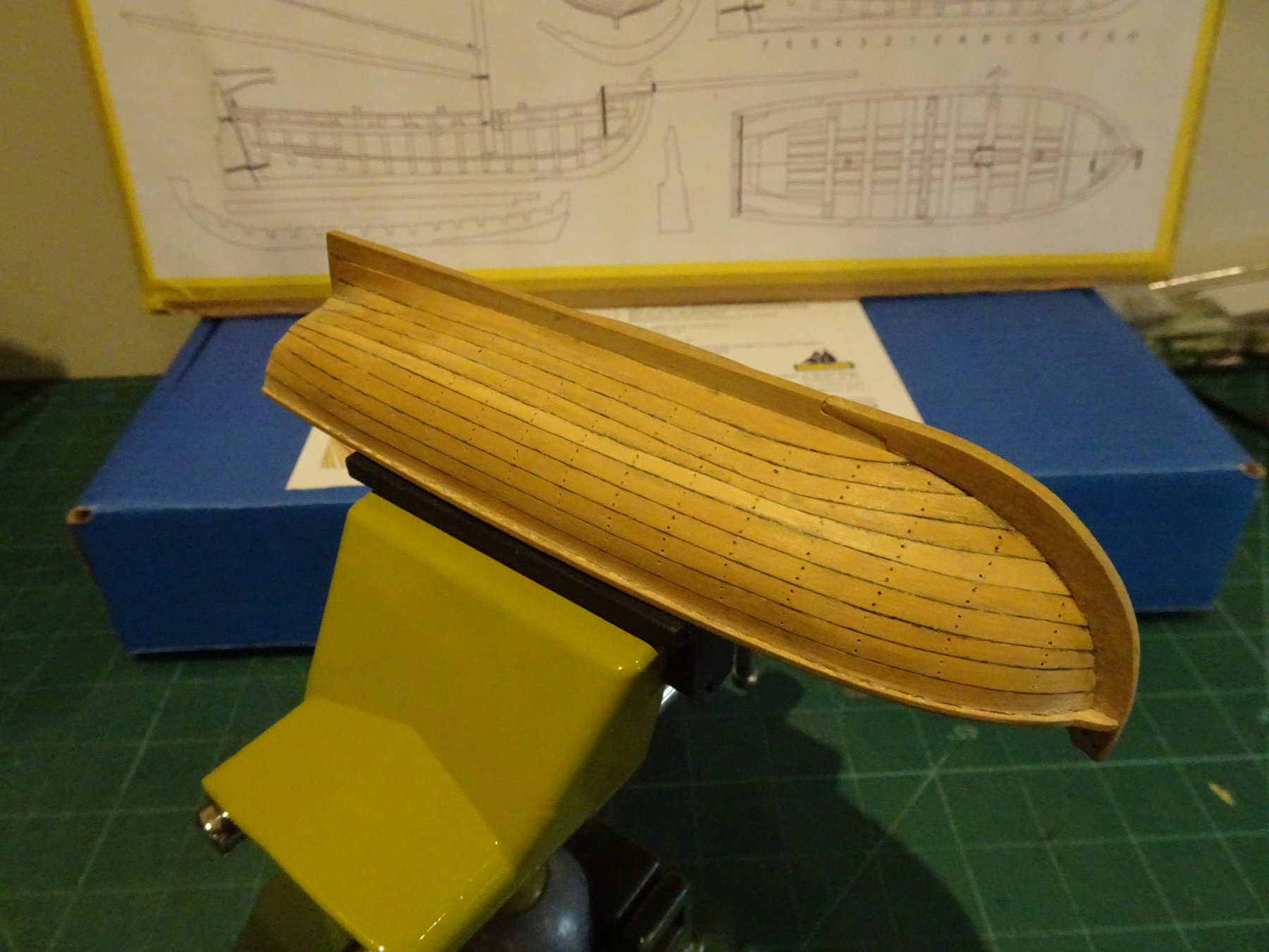
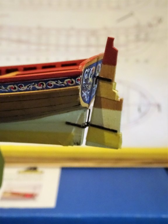
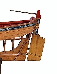
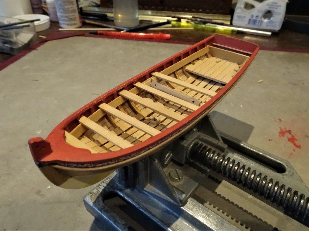
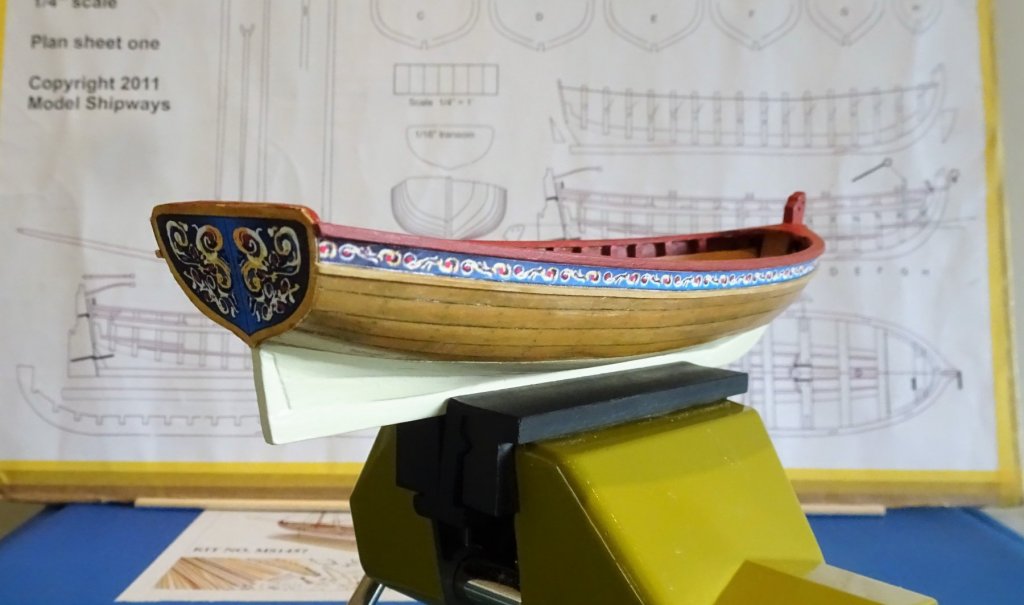
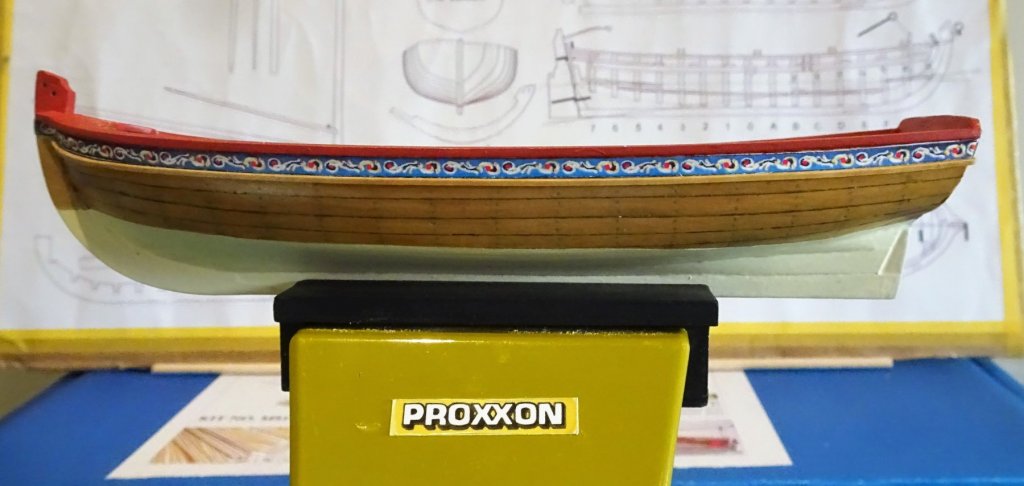
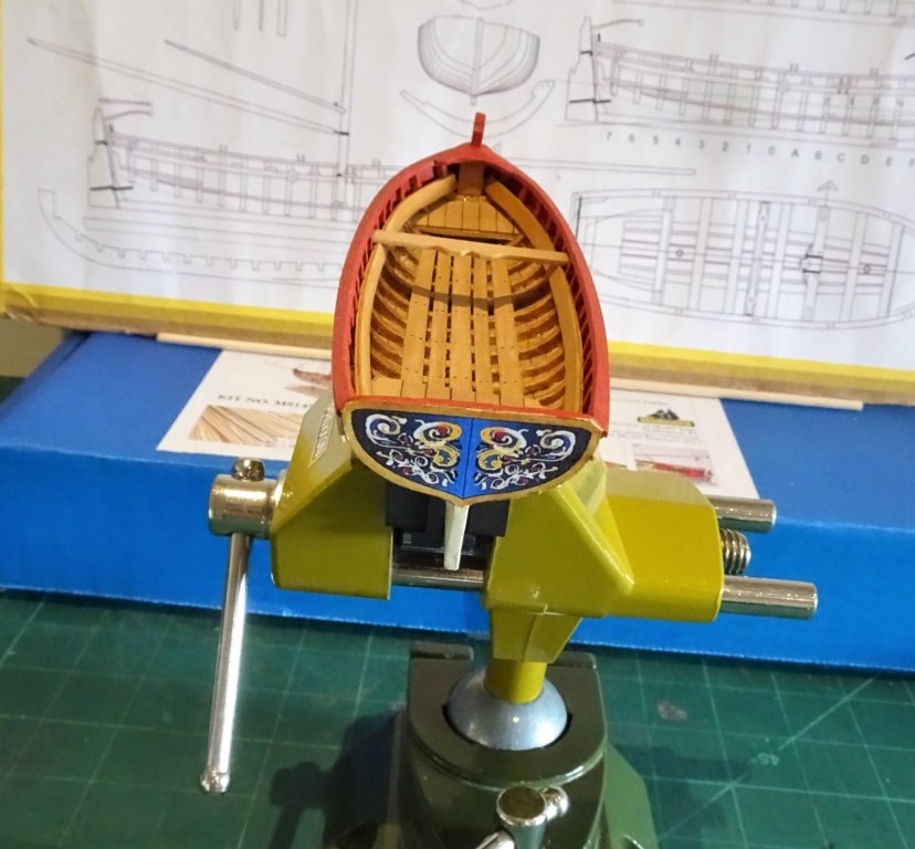
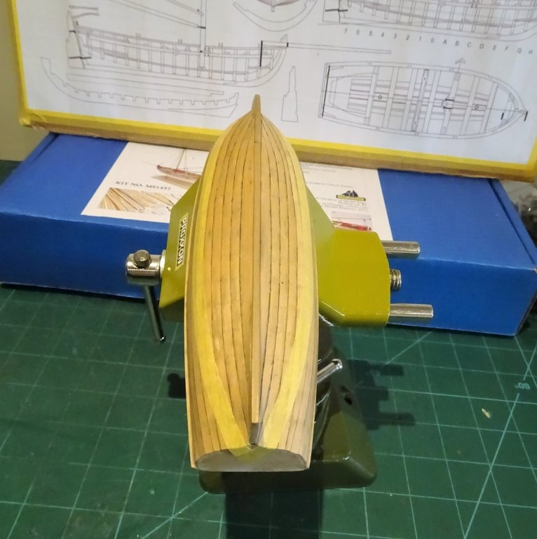
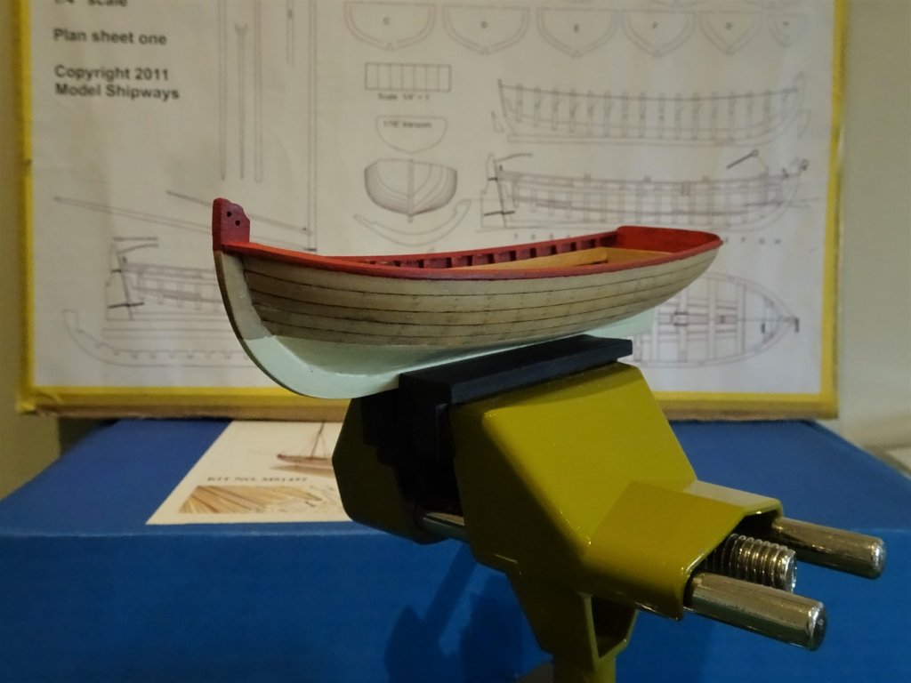
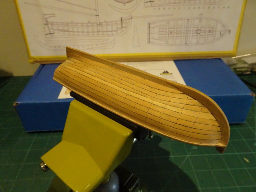
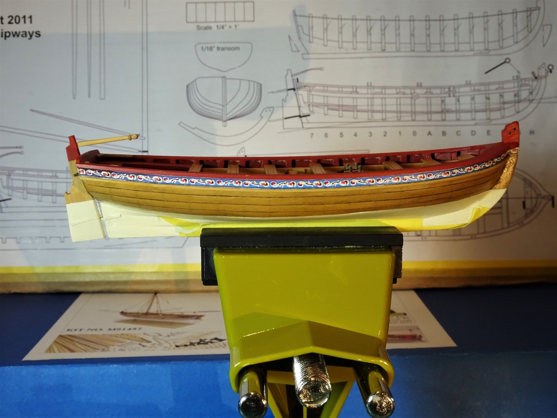
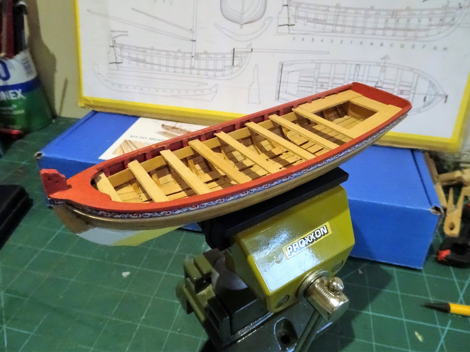
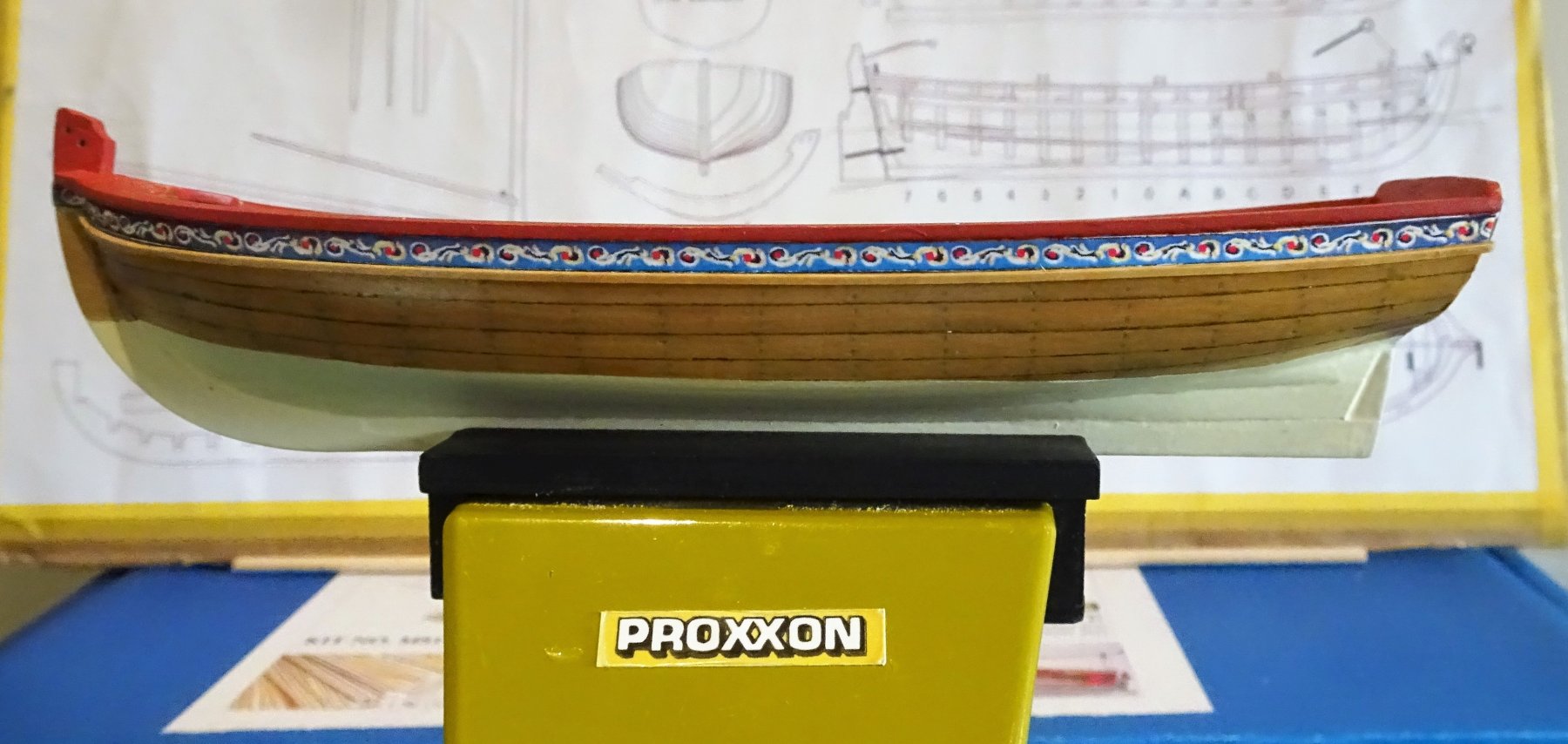
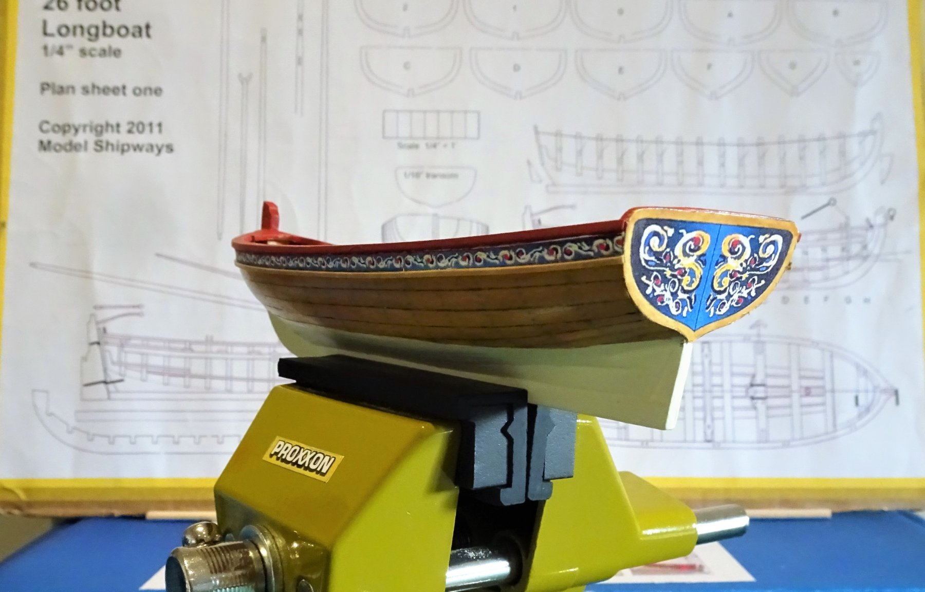
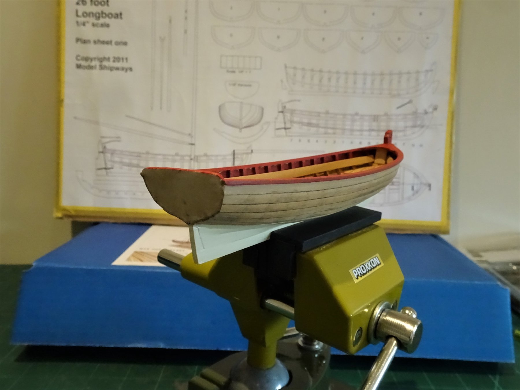
Cheers Bob and Jason, and for all the 'likes' Finishing the exterior. The decoration along the sheer is applied using pva and a 0.8mm square Boxwood strip applied below it as the moulding. 1500 Matt varnish is then applied to the decorative strip to seal it. 1493 The hull down to the waterline is then coated with Ochre enhanced satin varnish of the water based kind. Fairly happy with the treenailing effect along the hull, visible but not intrusive. The stern decoration was a little more involved. The kit provided patterns were far too large and would involve cutting away part of the design to fit. I downloaded the patterns provided by Chuck and the smallest version fitted just fine. I cropped and printed off several copies of this example on an A4 sheet to provide me with a few goes to get it right. 1494 As it happened the first attempt went on just fine using pva. The macro photo's reveal a little touching in is still required. A mixed blessing the macro lens, but at least it does act as an aid to failing eyes. 1495 The white border around the design was varnished over to match the hull. 1489 Not entirely sure I like the transom decoration, I think it has something to do with the greater depth and width of the transom on the kit model as compared to the NMM version. The NMM model has finer lines, a narrower transom profile, and greater depth of stern post which all reduces the impact of the stern decoration, more proportional I suppose. Fitting the rudder should help reduce the effect, something to ponder on awhile. B.E.


- 91 replies
-
- 20
-
-
- 18th century longboat
- model shipways
- (and 1 more)
-
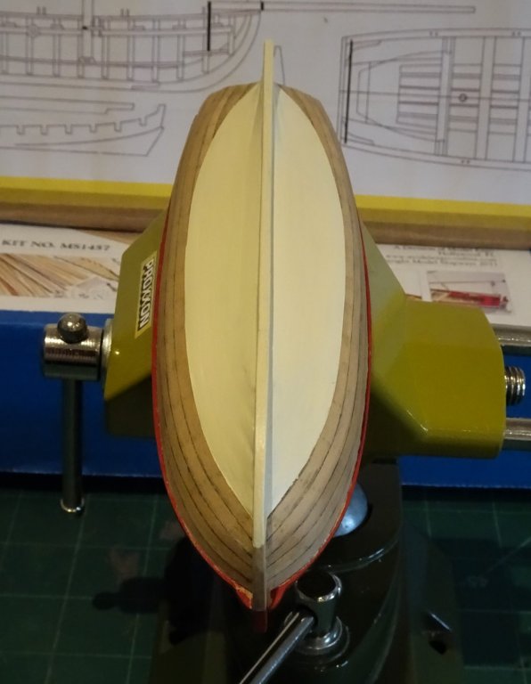
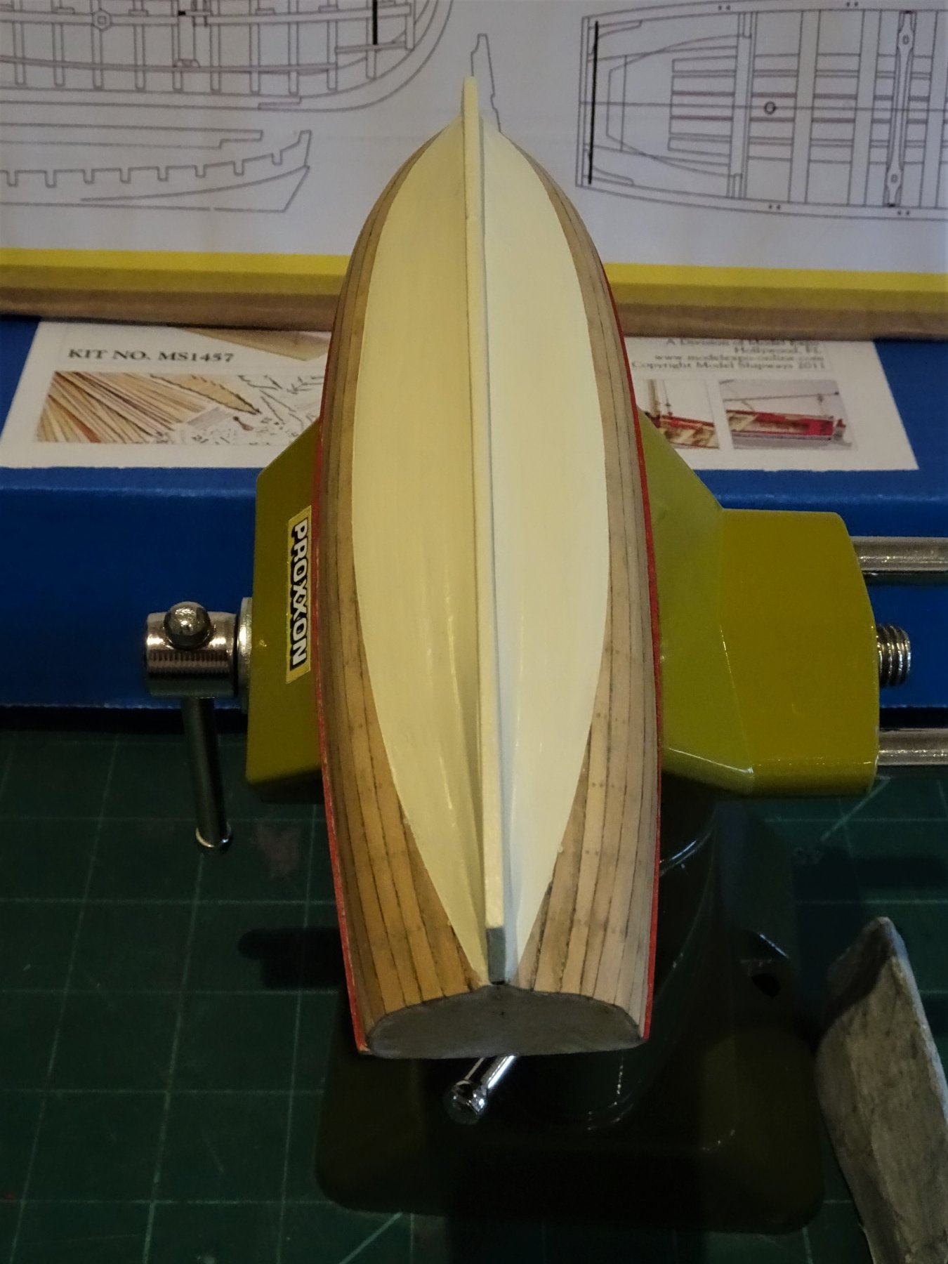
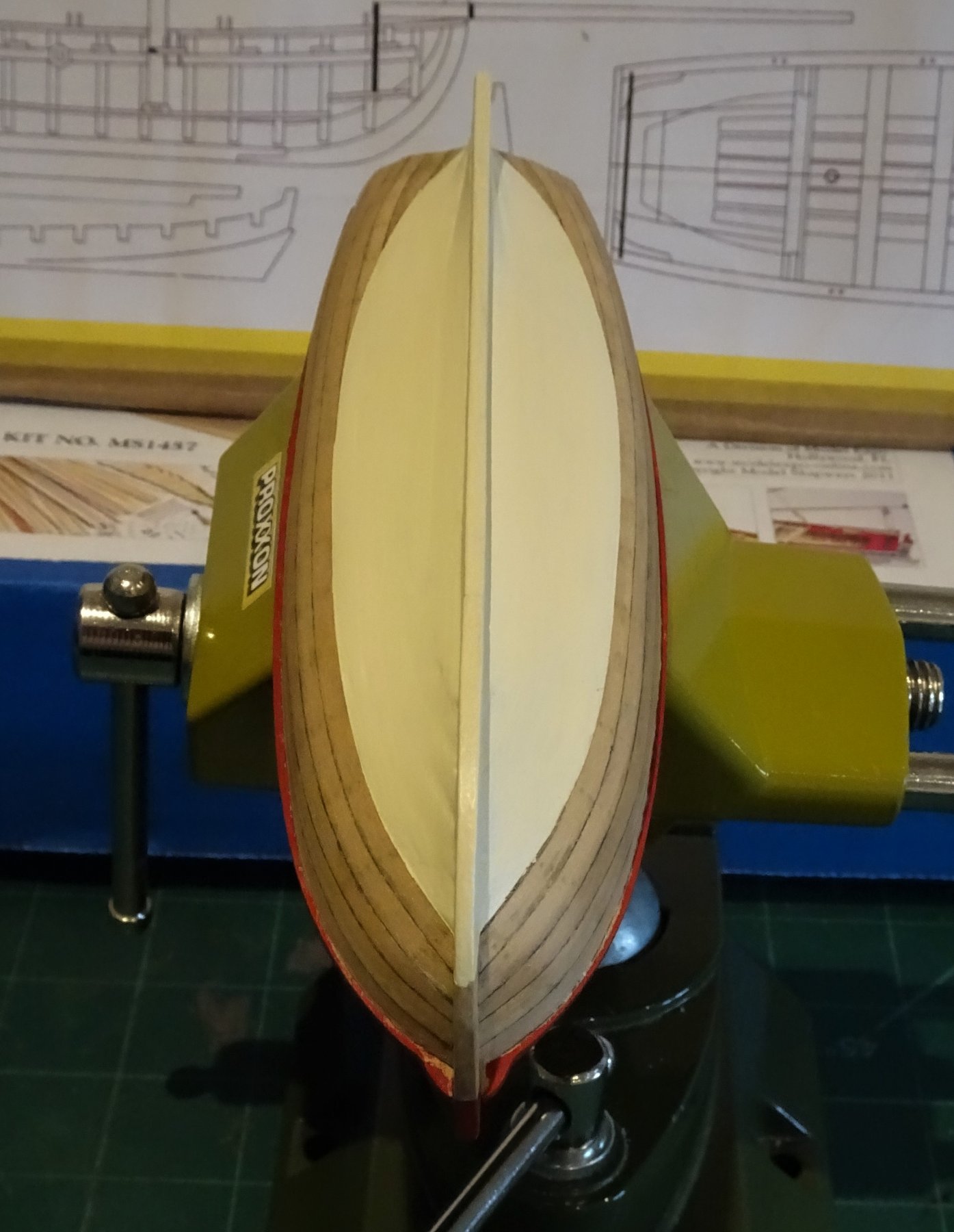
Thanks Derek and Steve, you're not kidding Steve, one to torture yourself with. but as I found with the Pinnace once past the planking part and into the detail, I became happier with the build. Thinking about the waterline. I had decided to paint below the waterline as per the contemporary NMM models, but the process caused me trouble. The waterline should run from the top of the stern post along to the stem, but I found getting this to look good ain't that easy. 1365 I fiddled around trying to get an even curve around the hull; I initially tried Tamiya tape for curves but it didn't seem to have much bite and kept falling off. I reverted to the usual yellow stuff which worked much better. 1370 So having achieved what I thought was a reasonable line matched each side it was time to bite the bullet. For this model rather than use white paint I decided to try a new 'Light Ivory' offering from Admiralty paints. 1469 It has a less stark appearance than white and is perhaps more scale friendly. 1470 This paint does seem to have a slight sheen on it so I will flat it out with Matt Varnish. 1478 1479 1480 At this point I have also laid some paint down on the capping rails. As with the Pinnace this is a mix of paints to achieve a tone that is pleasing to my eye. I am undecided as yet whether to paint the thwarts and cockpit seats red but this can wait. My inclination is to dispense with painting the Caprail edges and moulding strips white, a little too fussy for my taste, but it will also relieve me of a tedious painting job. Similarly a plain varnished edging to the Transom decoration will suit my eye better. In the next post I will complete the exterior of the boat. B.E.


- 91 replies
-
- 14
-
-
- 18th century longboat
- model shipways
- (and 1 more)
-
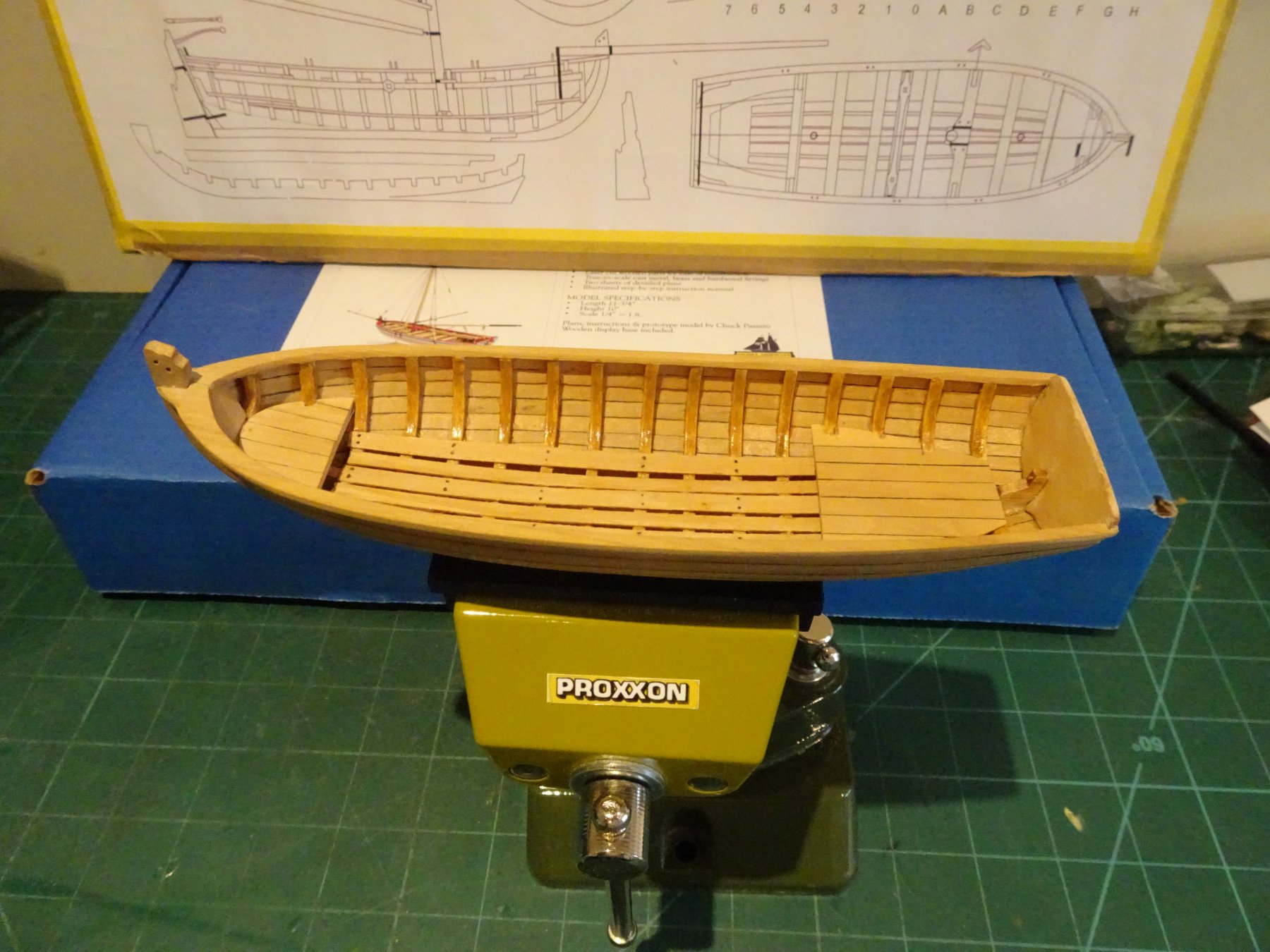
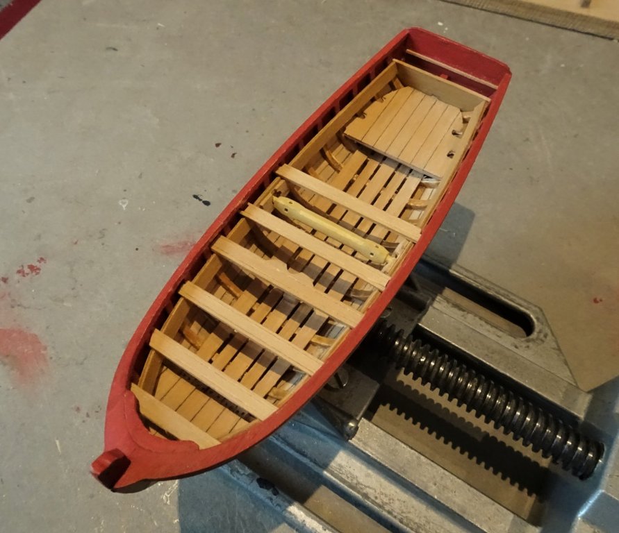
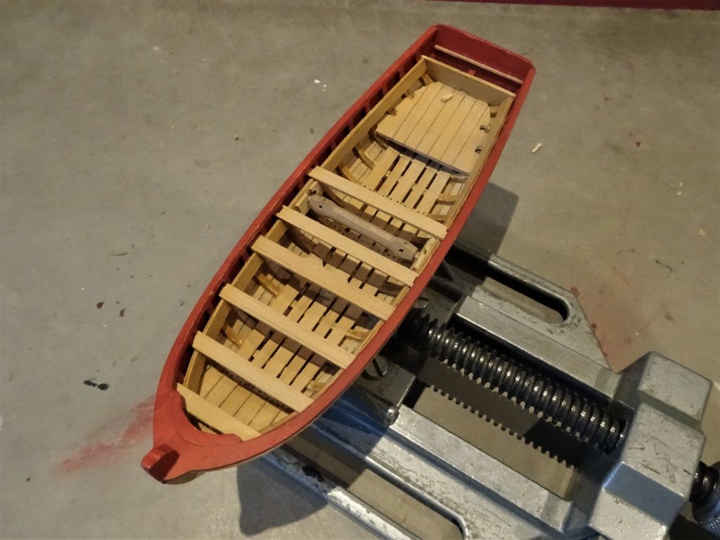
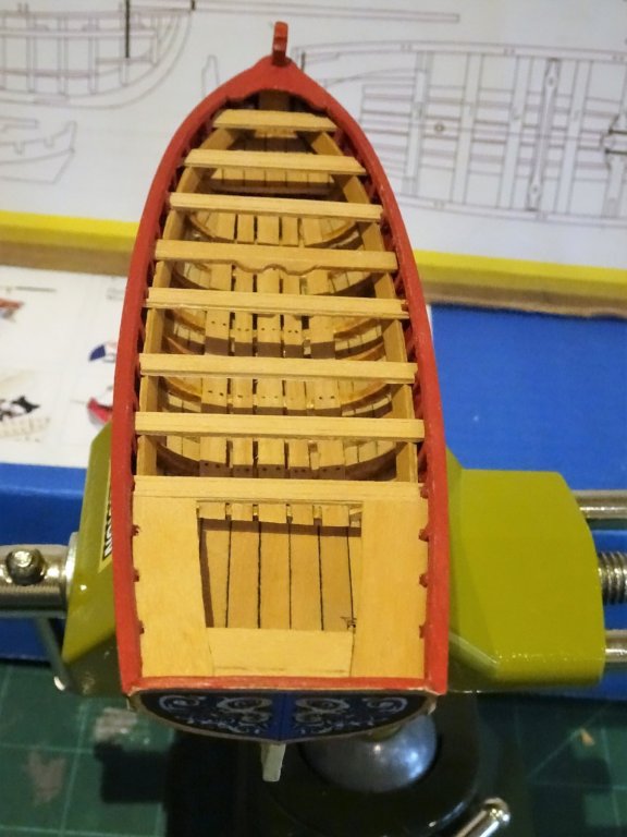
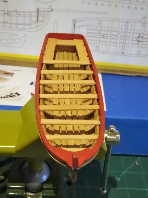
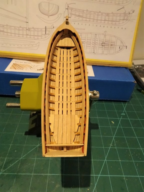
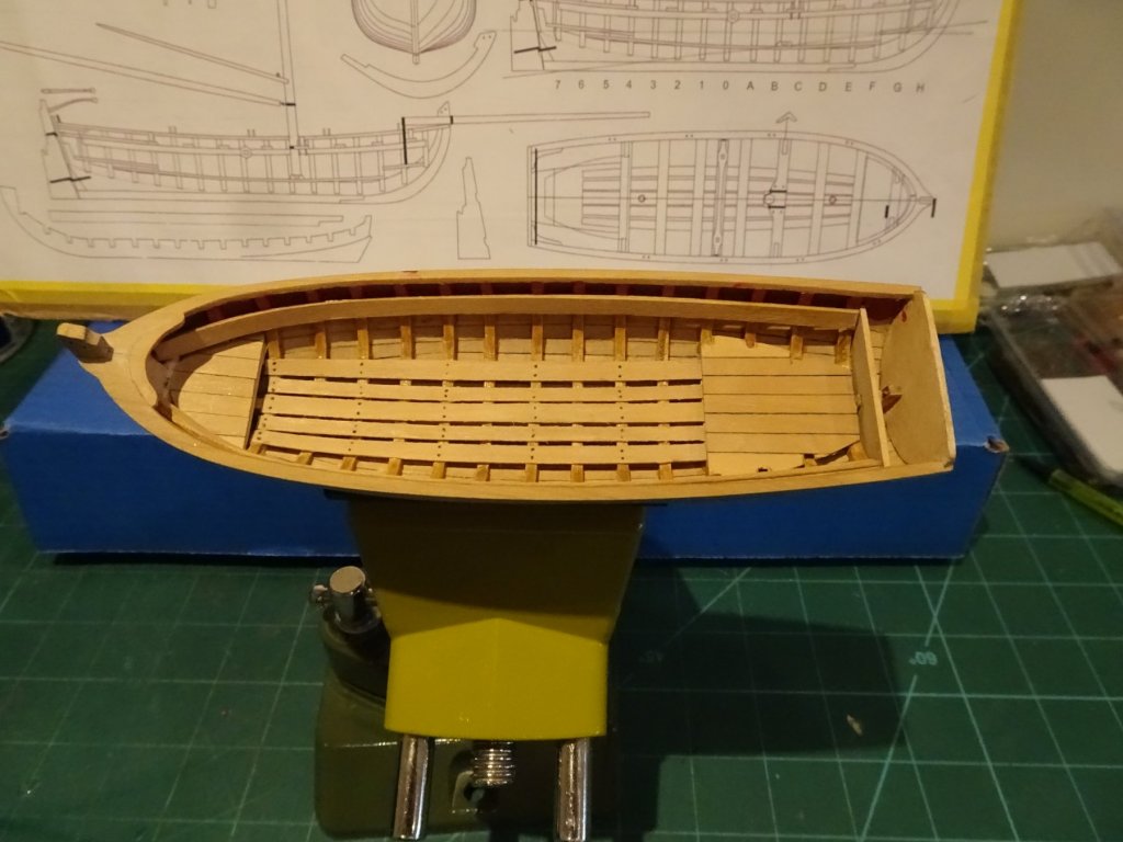
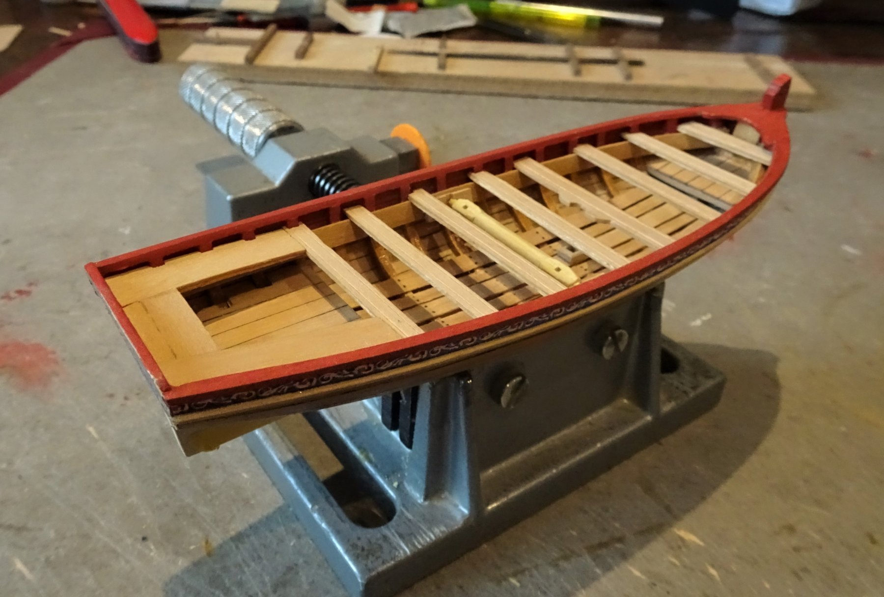
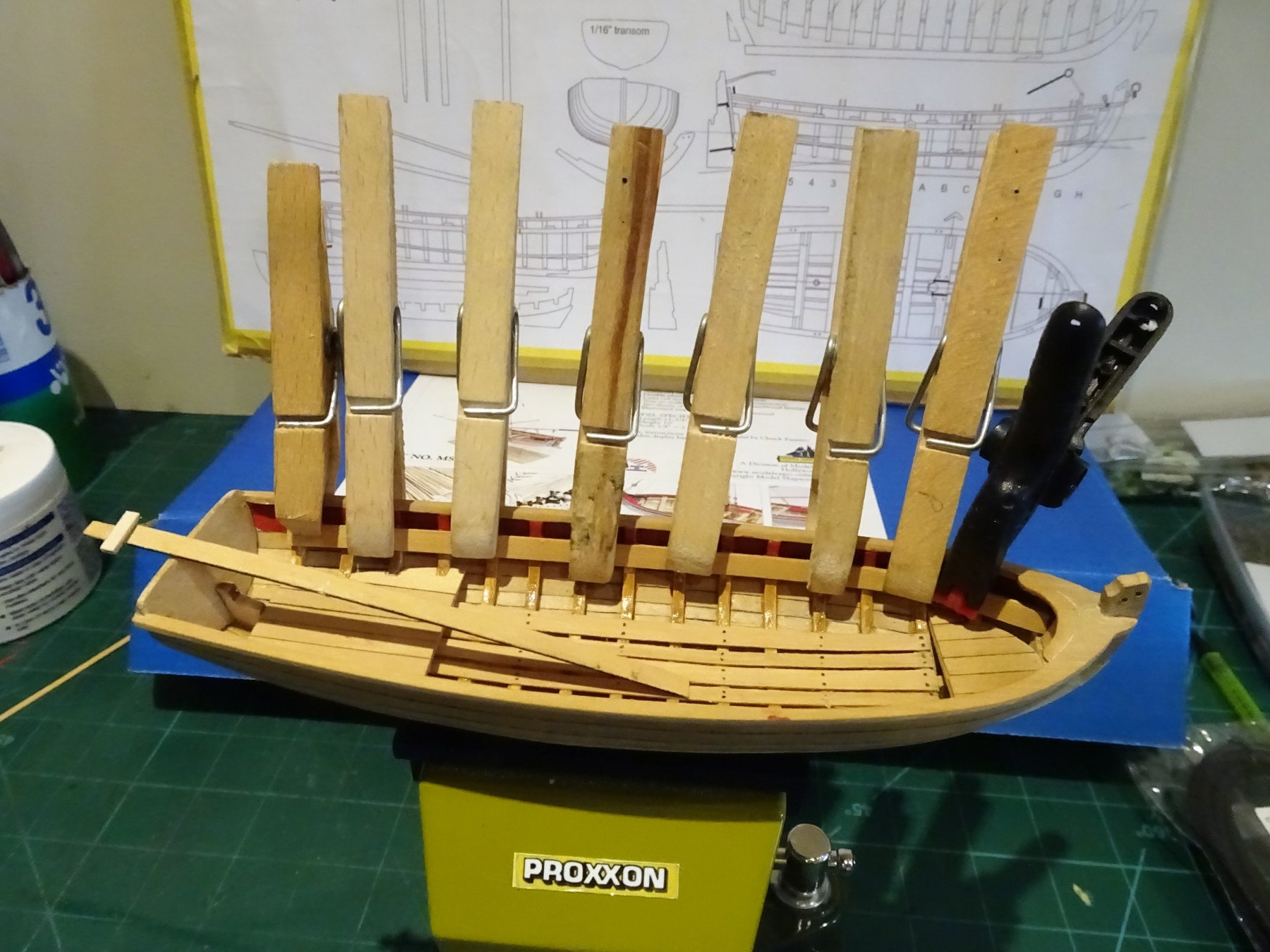
Raising the Risings This is a crucial part of fitting out the boat. The Risings support the thwarts, and if they are not level each side of the hull the thwarts will clearly not be horizontal, something that will be instantly be apparent and this will spoil the whole effect. I have used the kit provided Limewood strip, but I have faced it with Boxwood which provides a smooth clean surface. Note: The kit instructions indicate use of 5/32" strip (3.97mm) but the plan shows a narrower width of 2.5mm. I have gone with the wider stuff not least because of the Windlass fitting. 1457 A simple jig is used to mark the upper line of the Risings along the frames, and one side is glued into place. Once set the other side can be temporarily pegged into place along the adjacent line and temporary thwarts used to check the alignment. 1460 Satisfied with the second Rising position, it too is glued into place. 1464 1466(2) The knee at the bow is pre-cut in the kit, but I replaced it with a Boxwood version. At this point I also added the locker front in the stern sheets. 1467 I forwent the pleasure of scribing decorative lines along the Risings, but they will be added to the Thwarts. I will next be looking at the waterline. B.E.

.thumb.JPG.933b0f564c2aa2a9a93f4ea623401a31.JPG)
- 91 replies
-
- 17
-
-
- 18th century longboat
- model shipways
- (and 1 more)
-
Really nice work on the coamings Jason, great look👍 B.E.
-
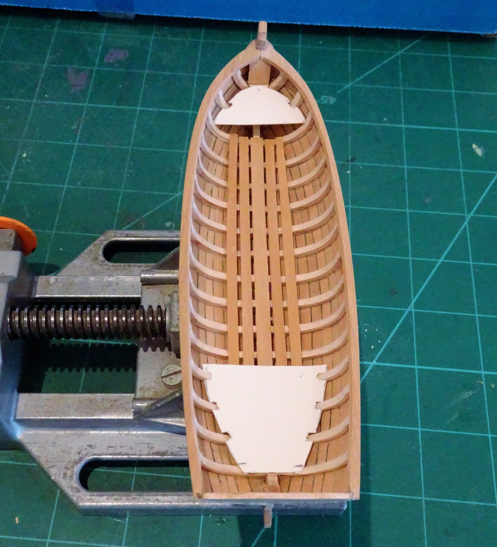
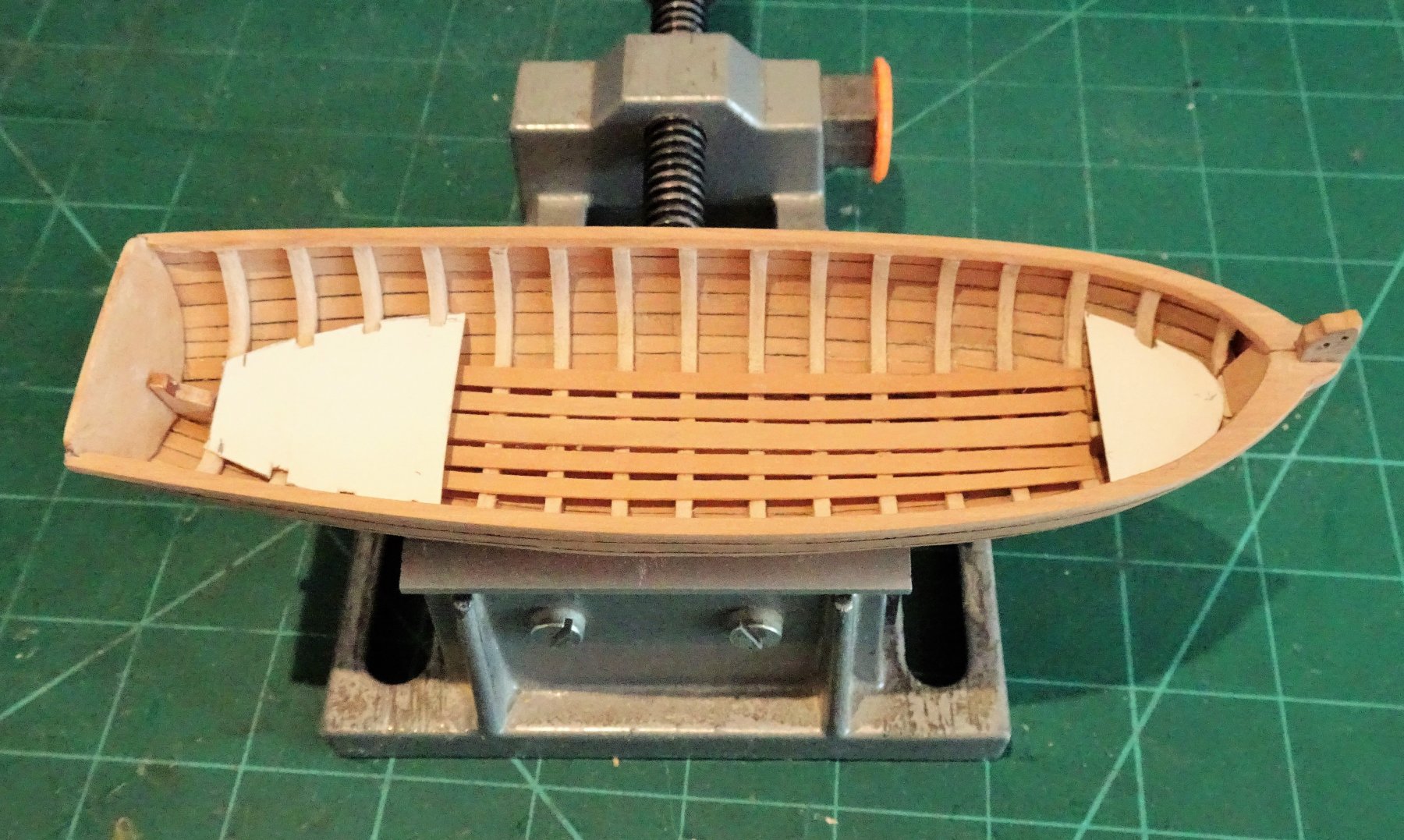
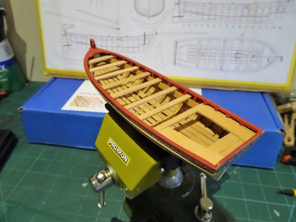
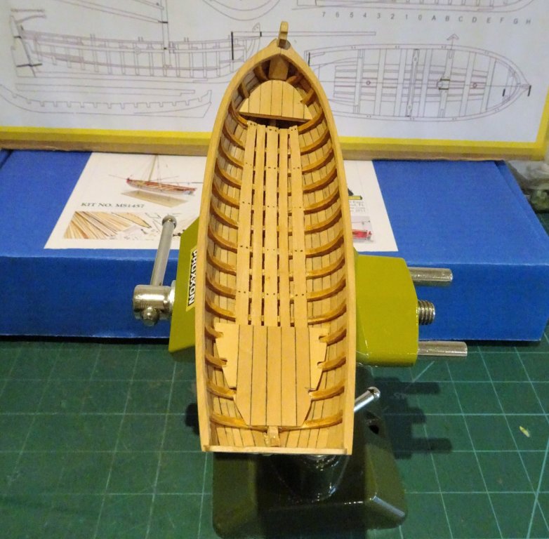
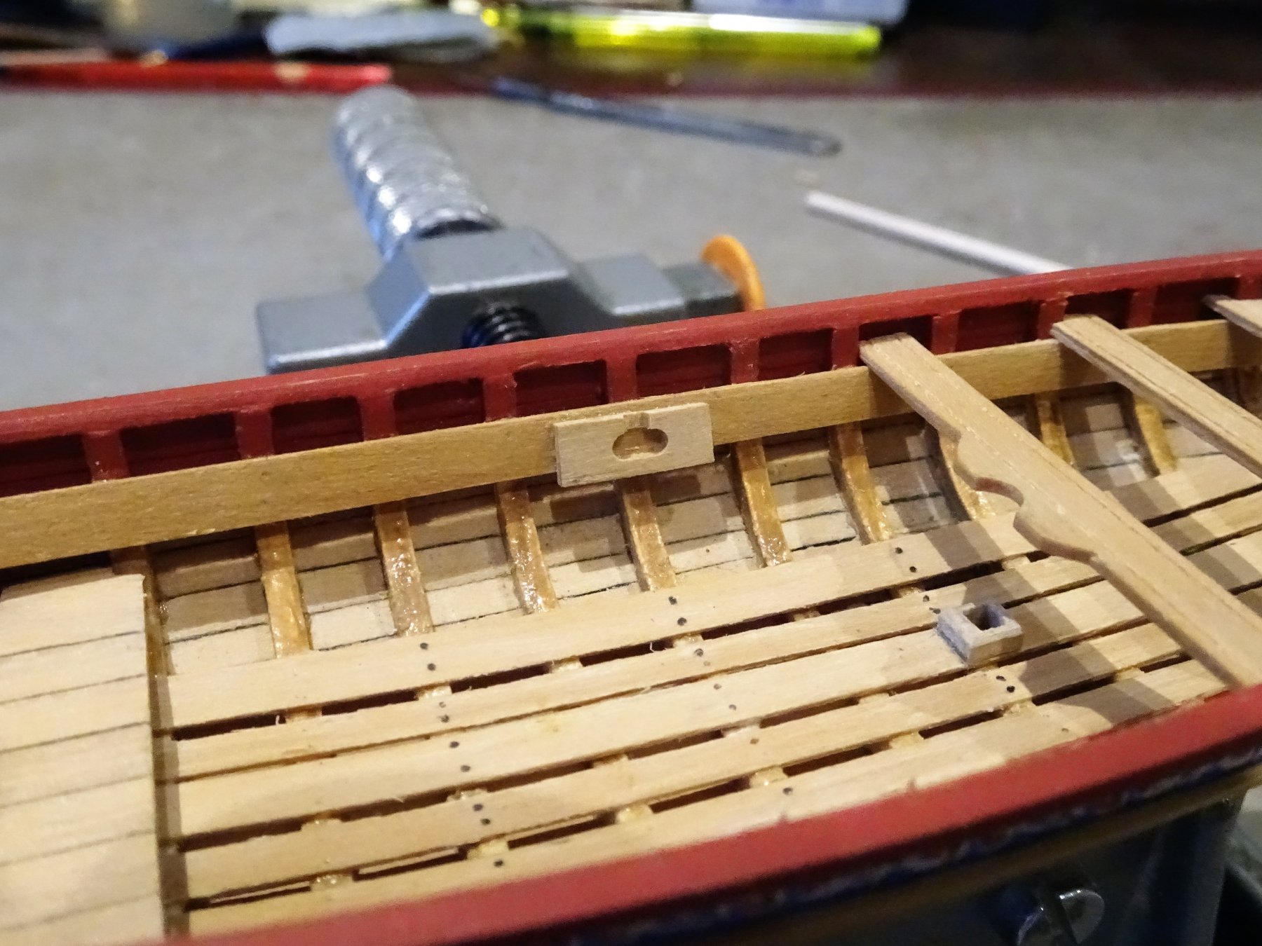
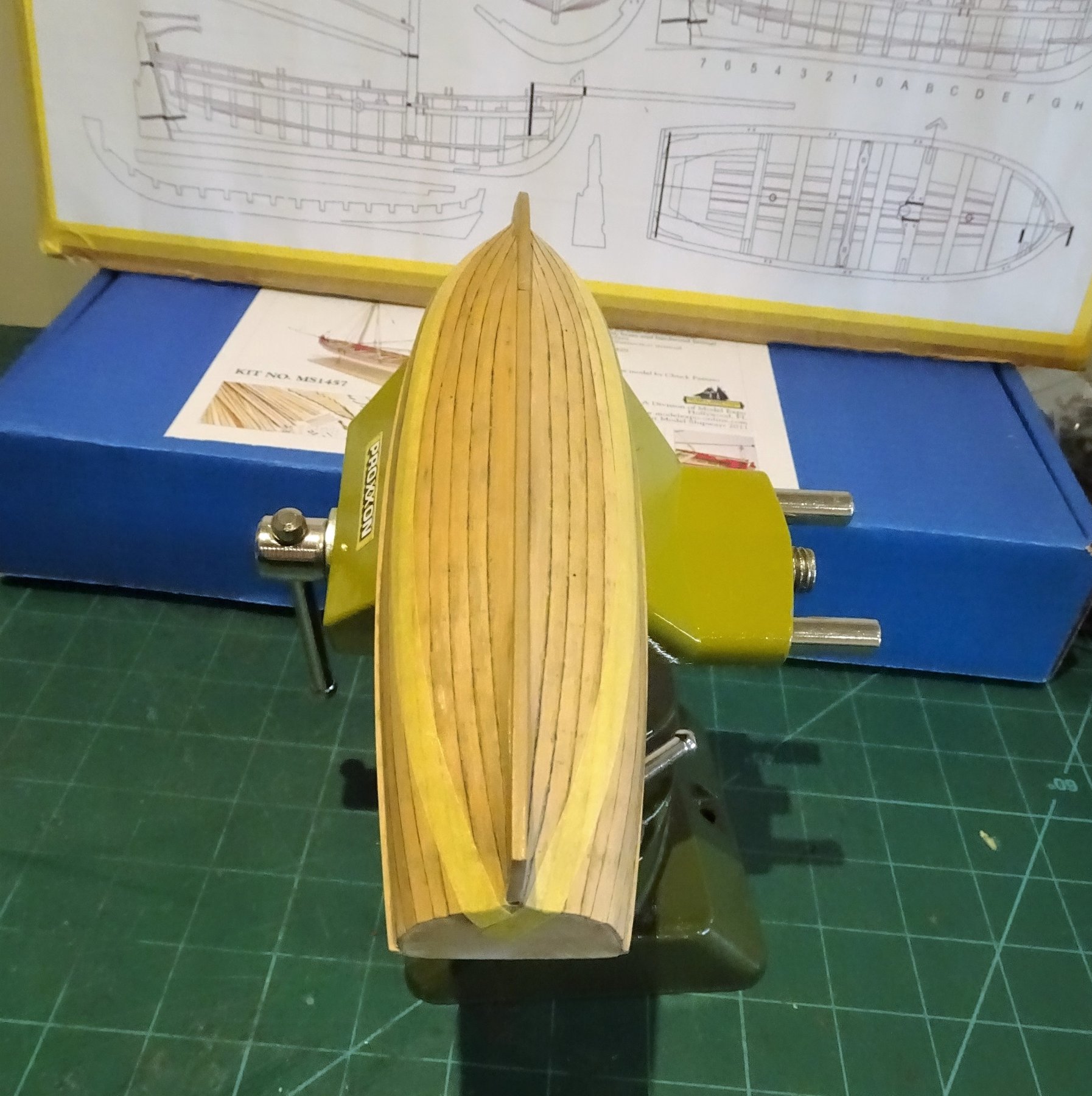
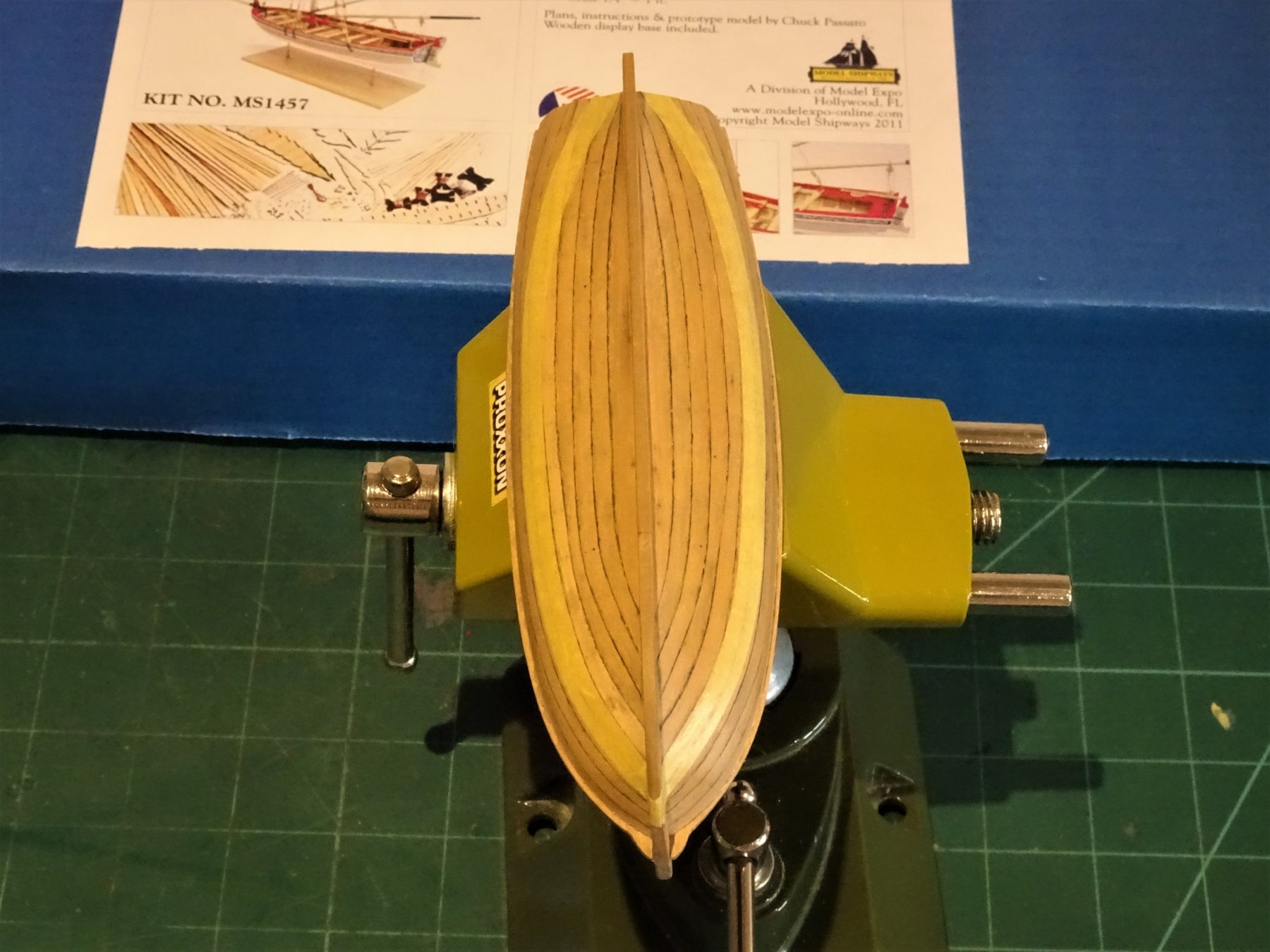
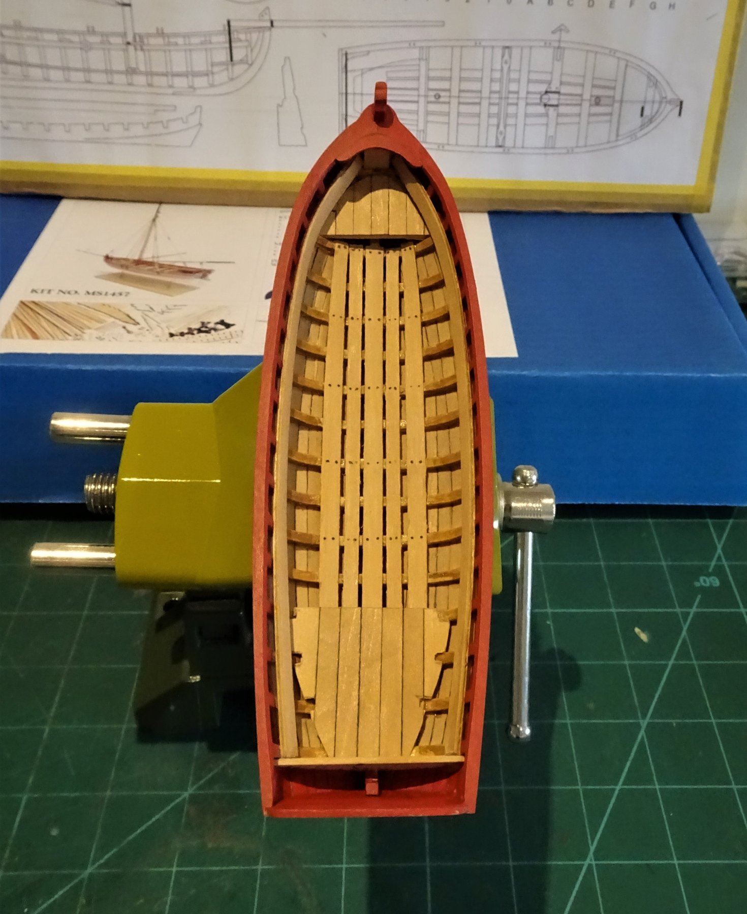
Cheers Martin, and thanks for the likes guys. Sand and check, sand and check, with the Longboat I resolved to reduce the frames to a finer profile than I did with the Pinnace, but the danger is that the finished job is quite fragile, and unlike the Pinnace there is no internal panelling to brace the hull, although there will still be the risers. 1339 I have now got the capping rail down to around 2.8mm and it looks about right to my eye bearing in mind that the thole pins will need to be inserted. The Footwalings are then put into place using Boxwood strip. 1338 For the stern and bow platforms a thin card template is used to get the fit and I then pva the Boxwood planks directly onto this, cut out the notches and the jobs done. 1347 I simulated nail heads in the footwalings by the use of yard brush bristles inserted into 0.5mm micro drill holes. 1349 The bow platform slopes to aft which is not really clear on the kit instruction photo's, but is apparent on the plan, and it needs to be low enough to allow the risers to pass over. 1354 At this point I also drilled micro holes (0.5mm) in the hull for the treenails. I will simulate these with coloured filler. The hull exterior can then be cleaned up. B.E.


- 91 replies
-
- 13
-
-
- 18th century longboat
- model shipways
- (and 1 more)
-
Fine job on the stern area Bob, love the glazing effect, gives a nice period look. 😊 B. E.
- 682 replies
-
- 4
-
-
- halifax
- lumberyard
- (and 1 more)


.JPG.86ad68d000c64ad39e55583e3a87622b.JPG)