.JPG.ca33079f5815b861e67b9c2cccd37982.JPG)

Blue Ensign
-
Posts
4,564 -
Joined
-
Last visited
Content Type
Profiles
Forums
Gallery
Events
Everything posted by Blue Ensign
-
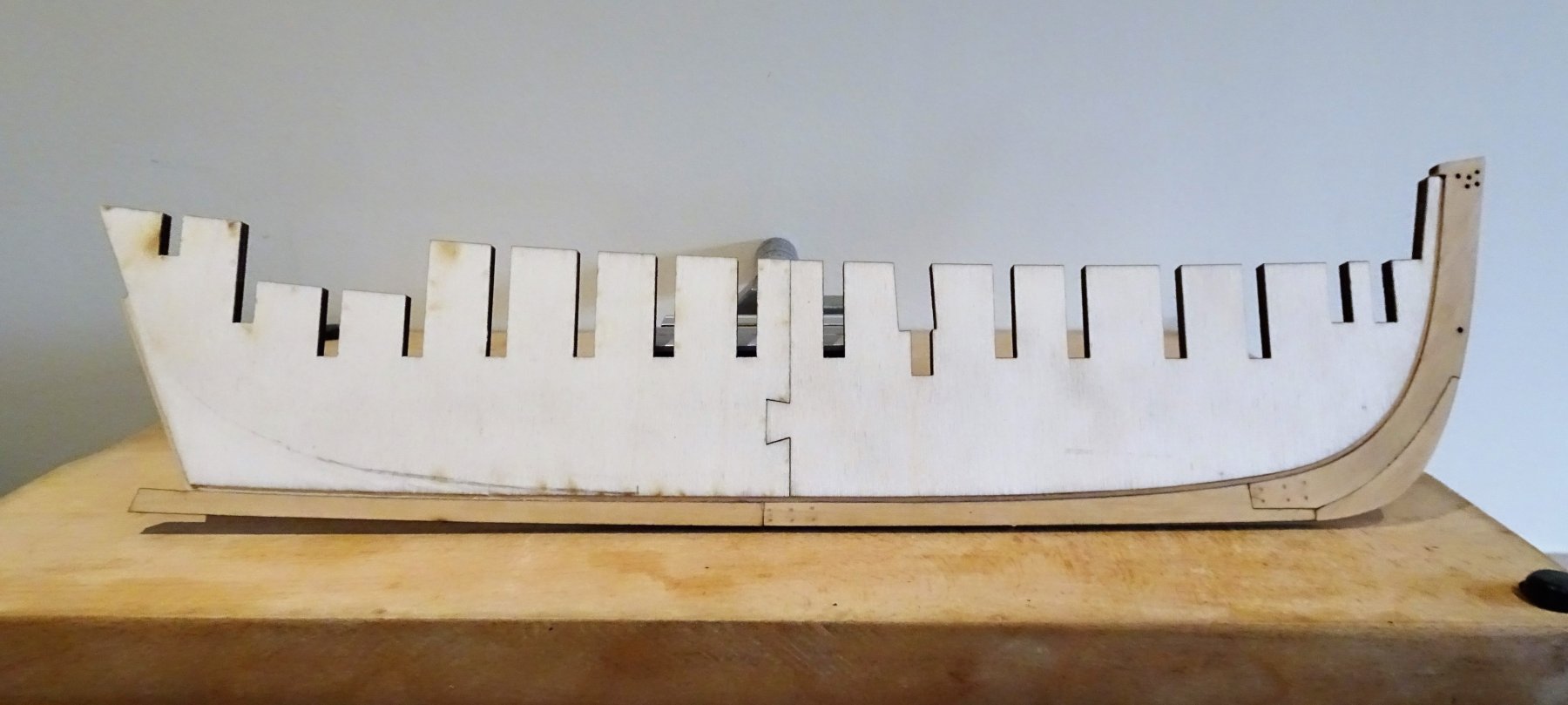
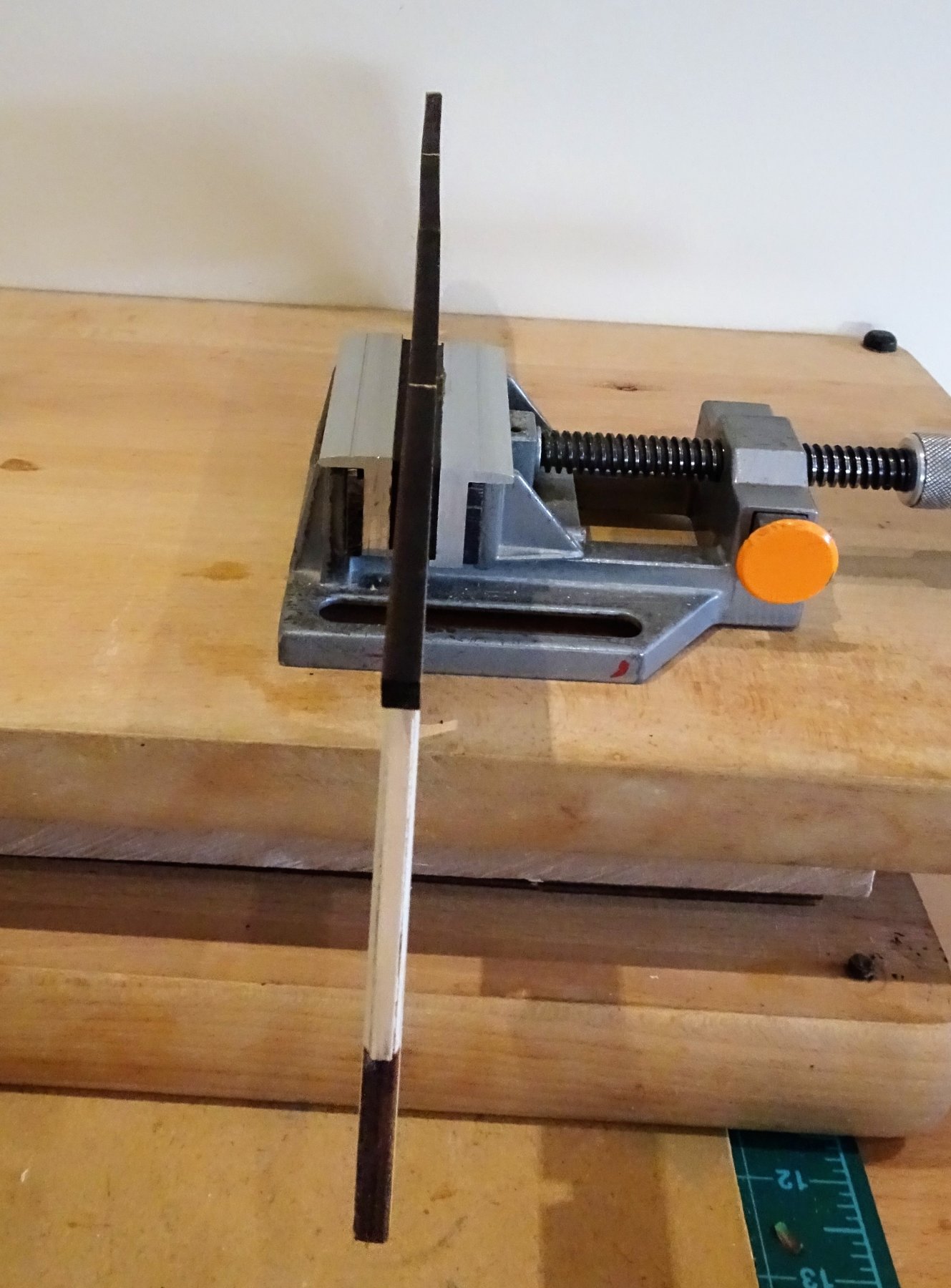
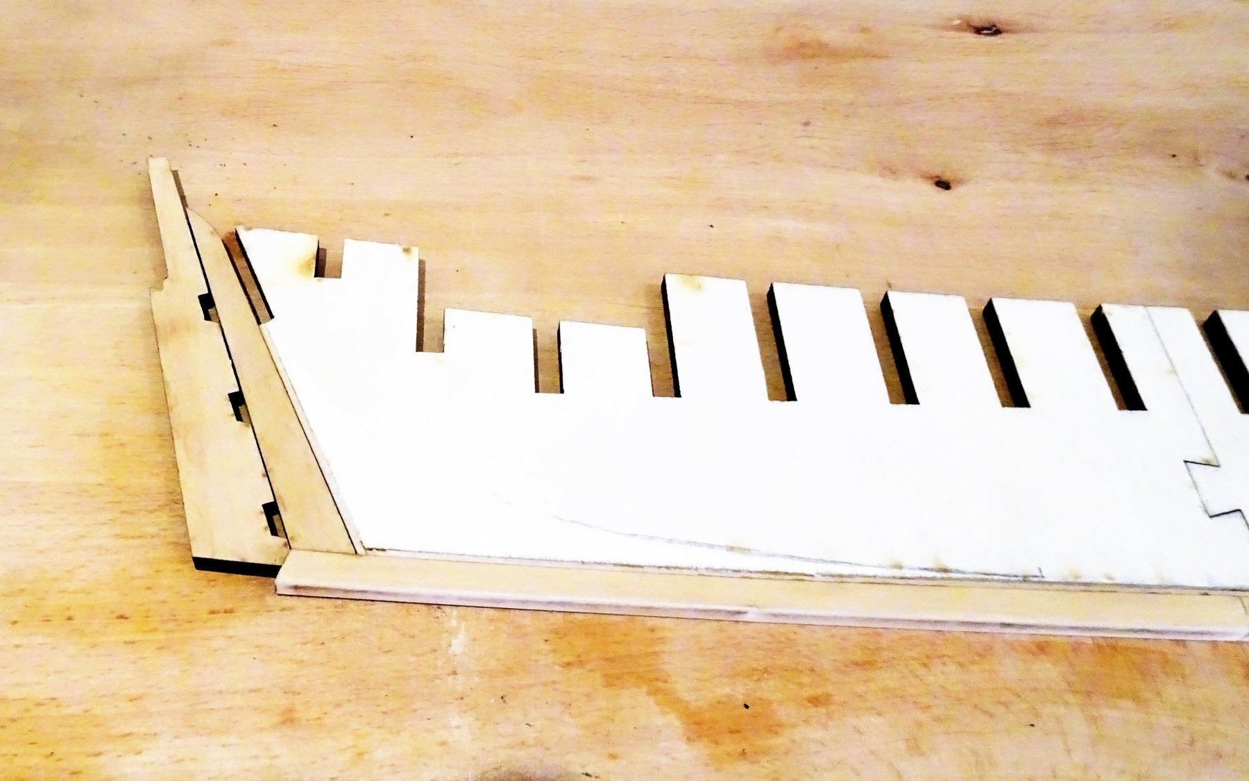
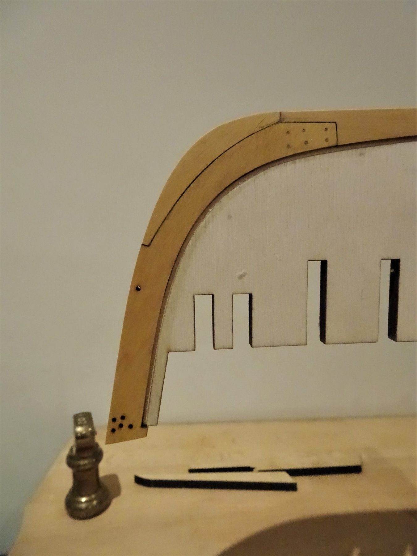
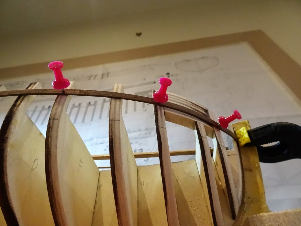
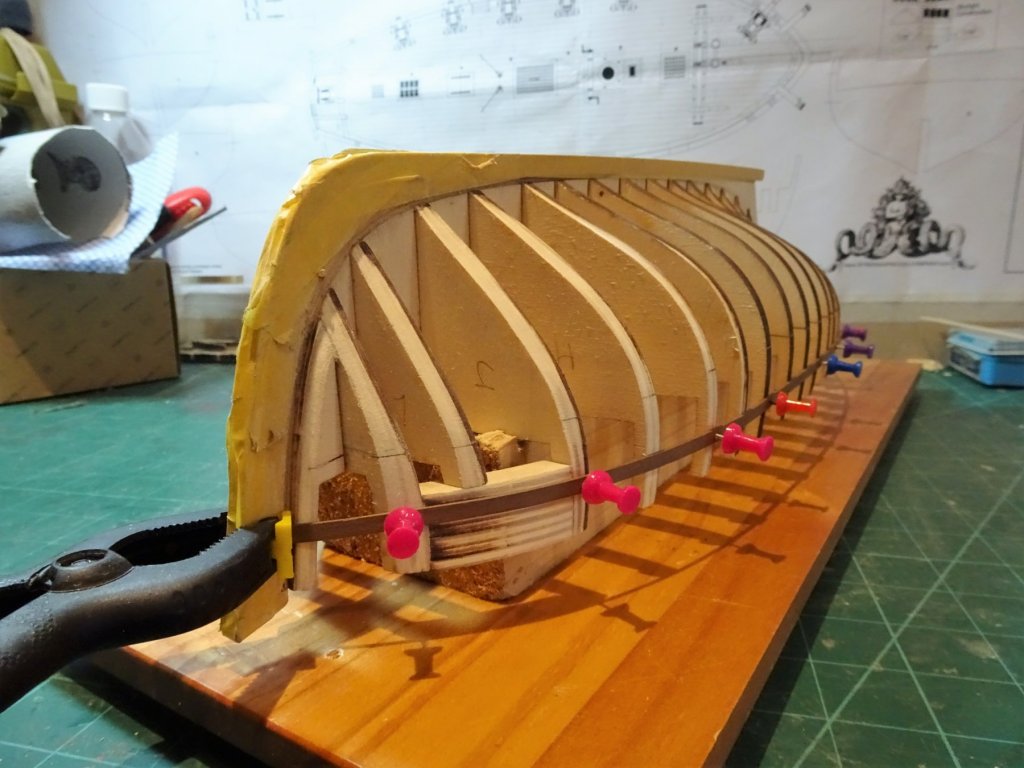
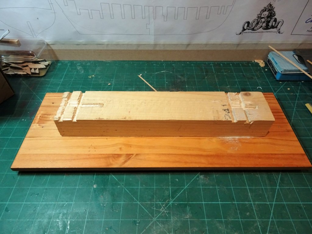
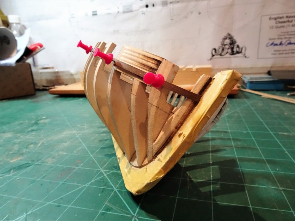
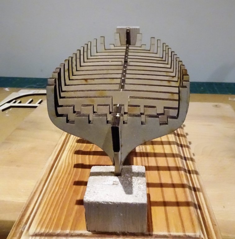
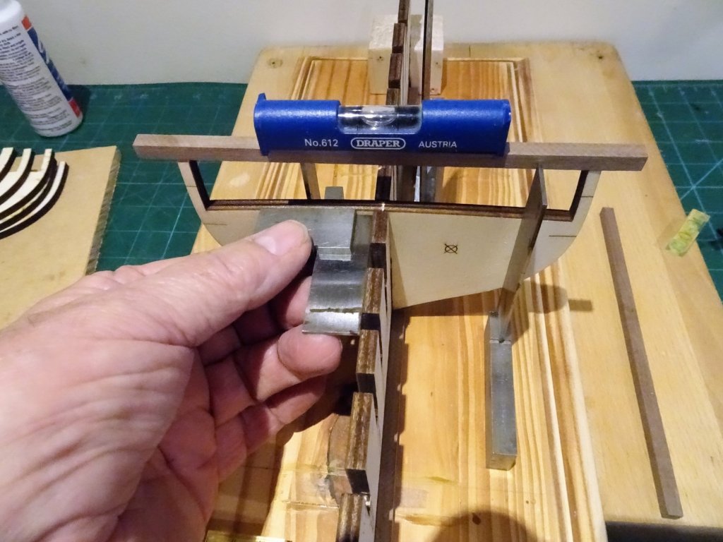
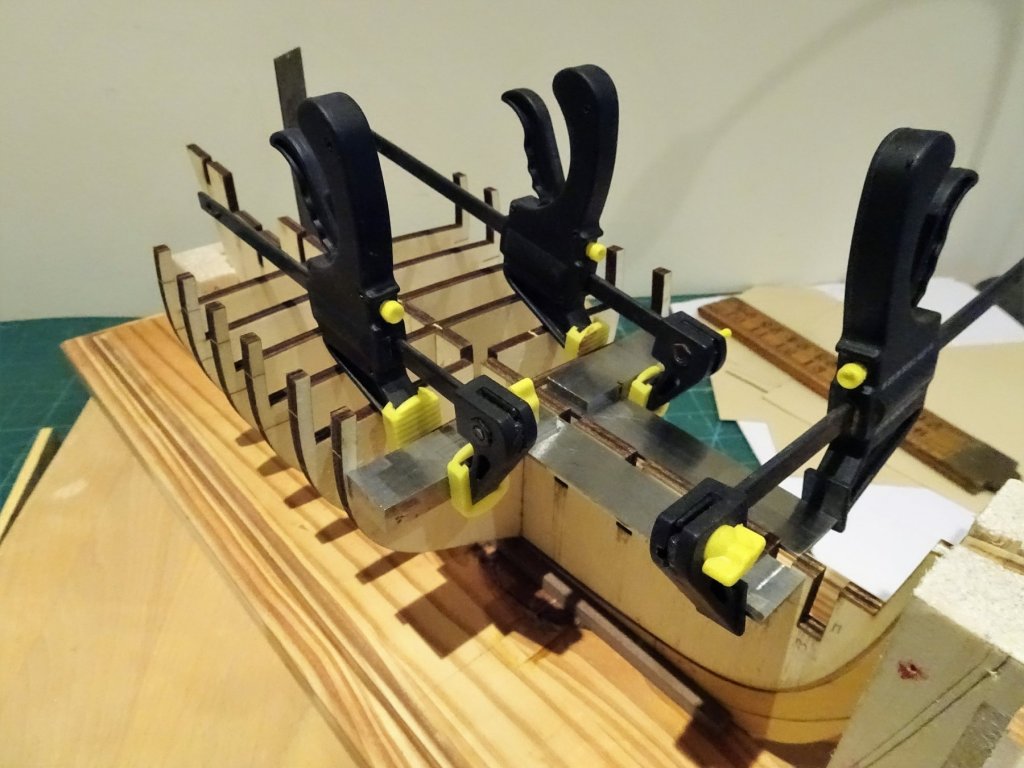
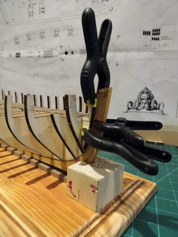
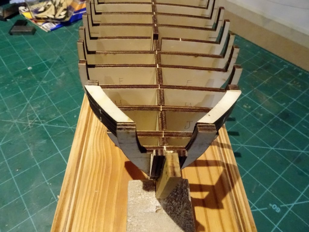
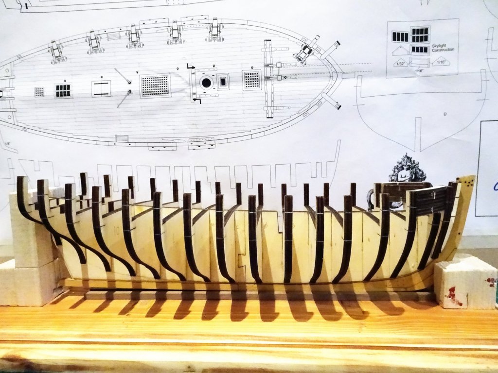
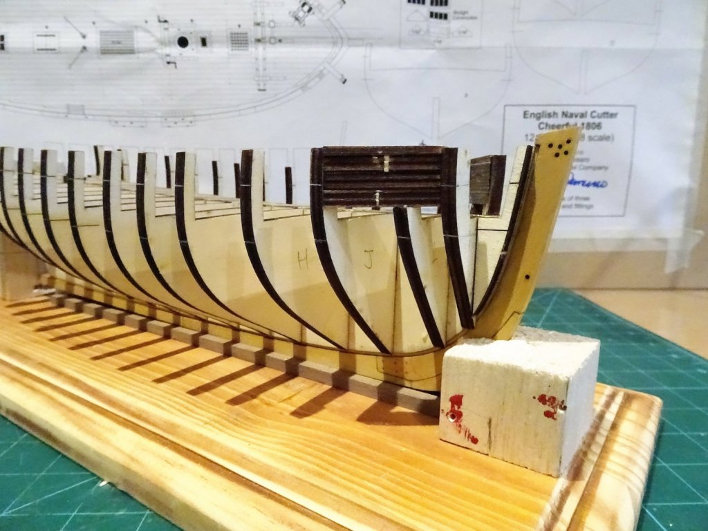
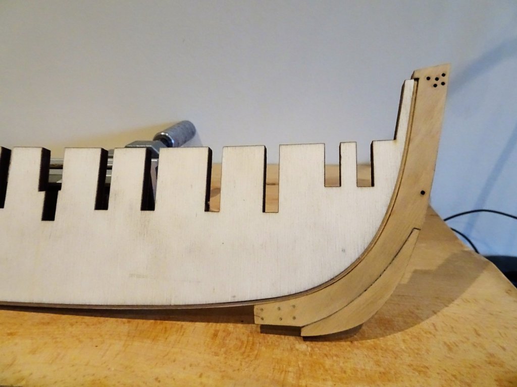
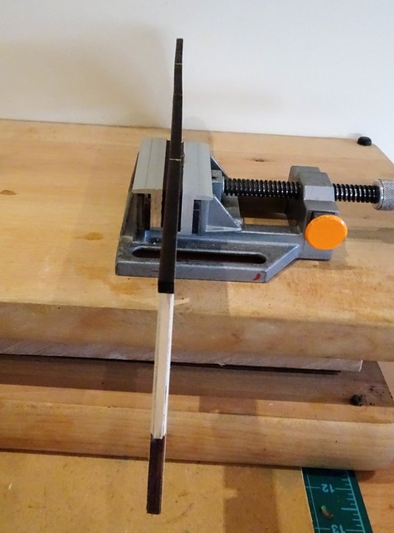
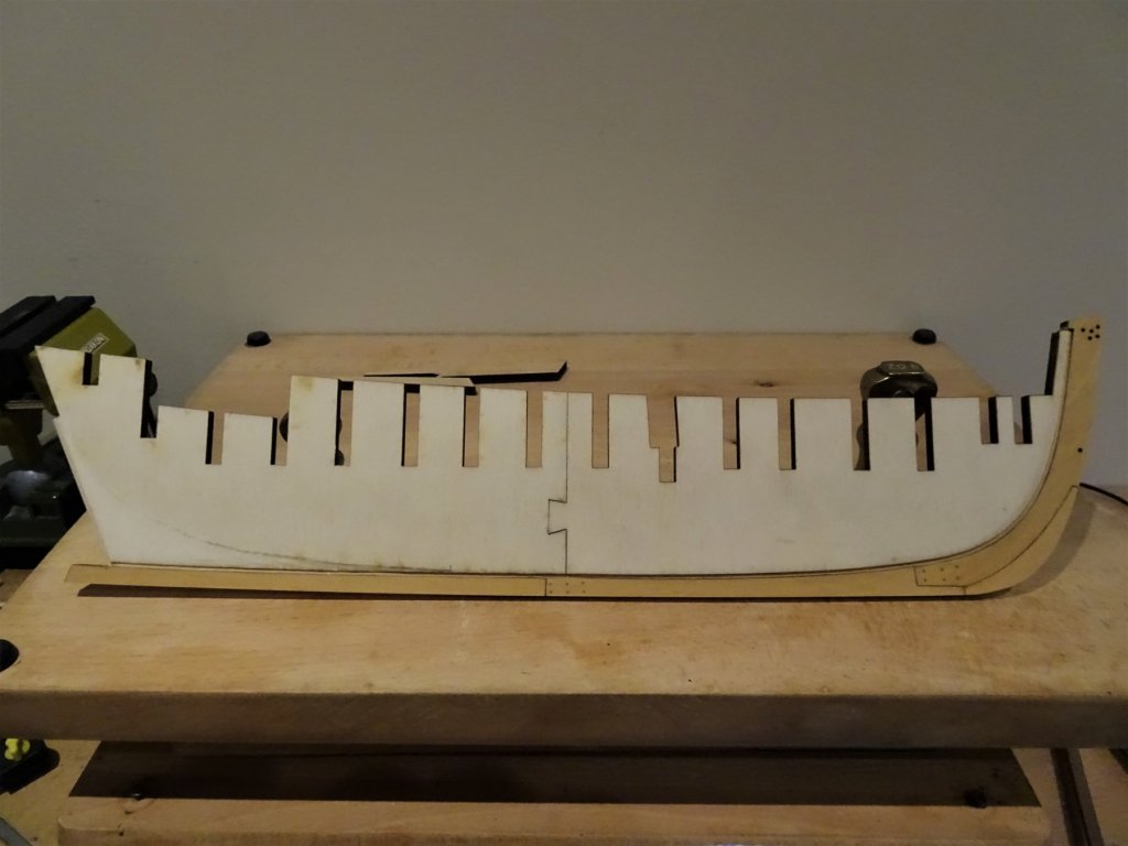
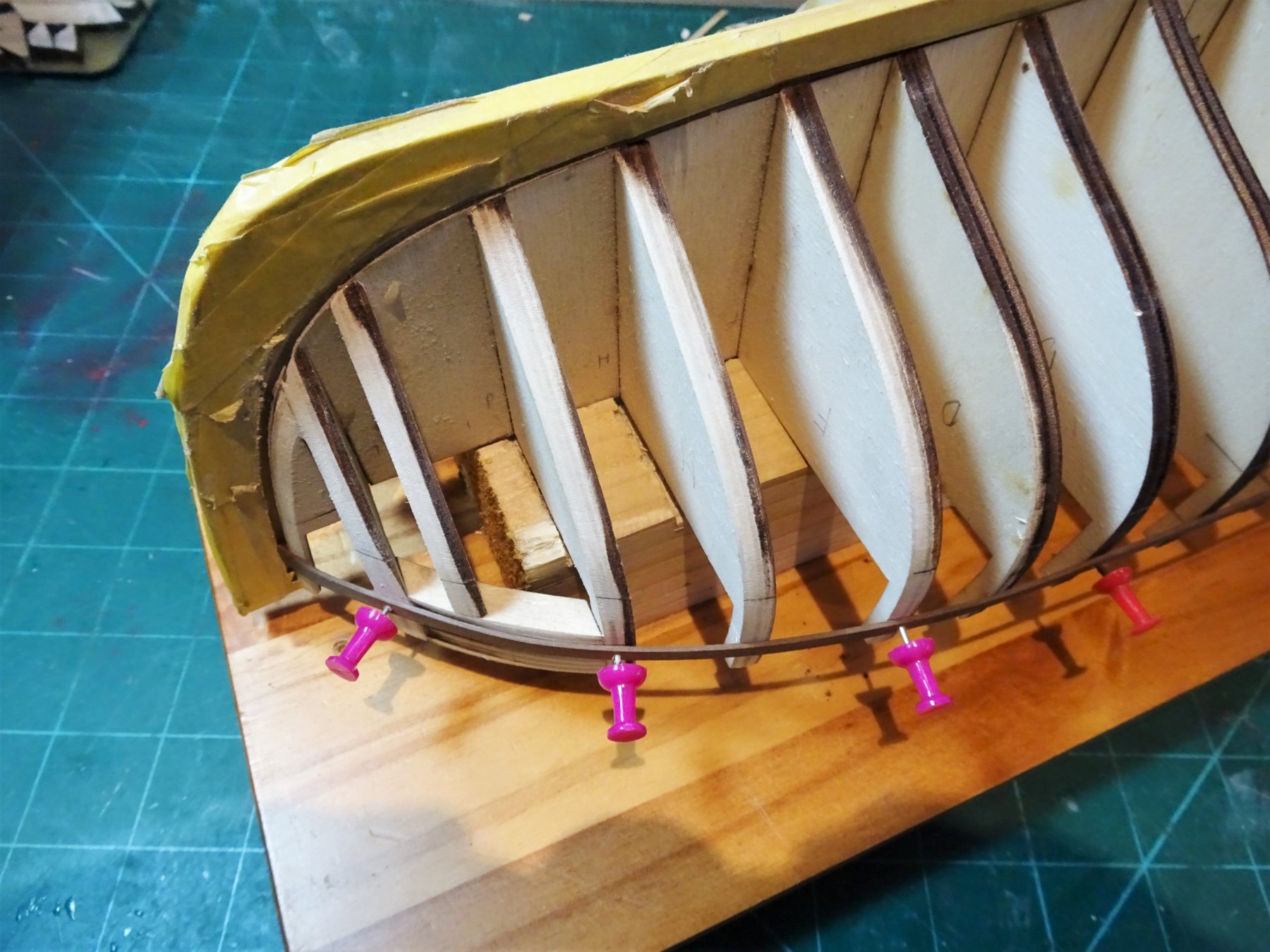
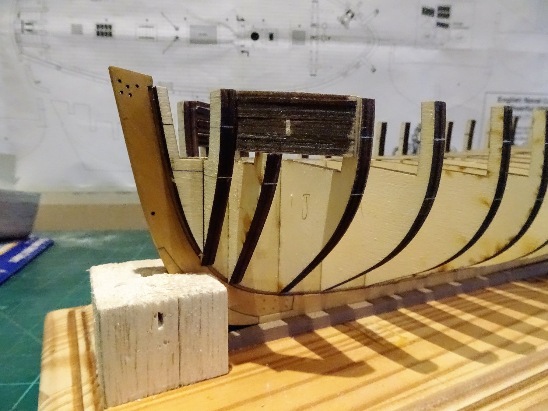
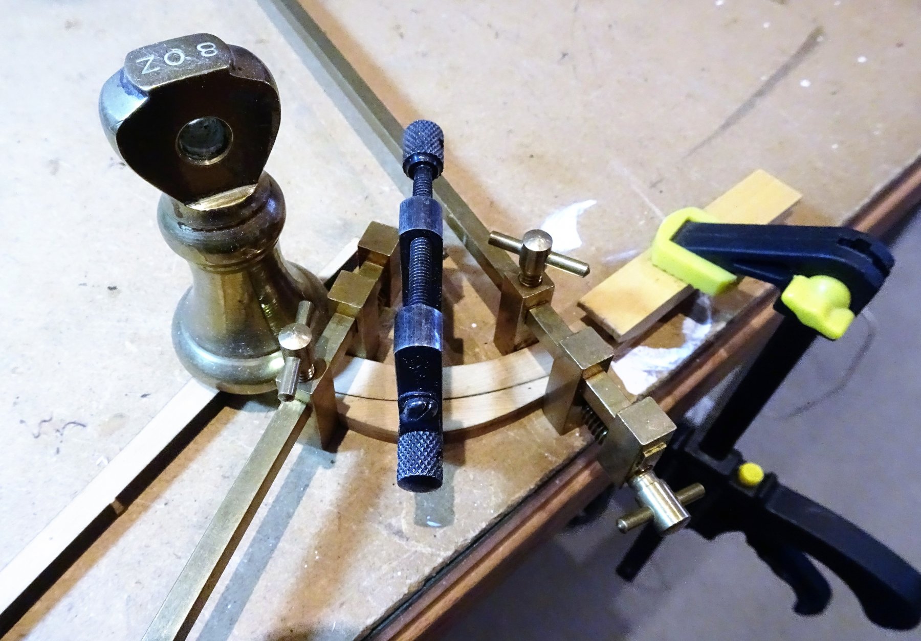
 Thanks Mike and Dave, and belated New year greetings to yourselves. Post 6 That fairing business Not done much work in the Shipyard since before Christmas, lacking some enthusiasm most probably because one of my least favourite aspects of a build is now required. Fairing seems to go on forever, and there is always the worry in the back of my mind that I may overdo it, and end up having to shim the bulkheads. 4024 One needs a good supply of sanding sticks for this task and I've added to my supply a curved stick made from a strip of Yellow pine left over from a much earlier scratch build of a twelve gun Brig, put into ordinary for many years and then abandoned due to terminal wood worm. The wood comes off pretty easily during the bevelling operation, but the devil is as always in the detail of the process. 4469 I made a simple block jig to support the inverted hull whilst working. 4467 Once I reached the point where I felt there was a smoothish transition a walnut batten was pinned along the hull at gunport cill level. 4474 getting there I think, at least on the starboard side. 4470 4472 4462 4473 The fairing continues, a further batten strip will be added at Wale level, and a third lower down. B.E.
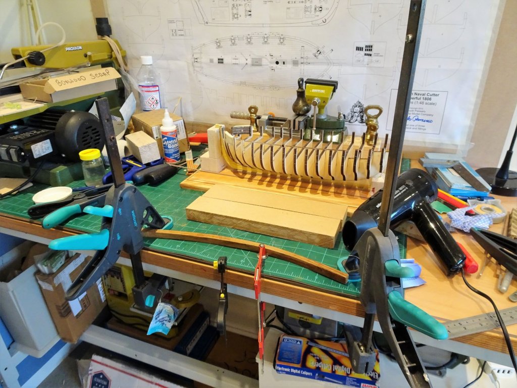

- 574 replies
-
- 16
-

-
- cheerful
- Syren Ship Model Company
- (and 1 more)
-
Neat and clean and beautifully presented as always Bob, another fine example of your talent. B.E.
- 682 replies
-
- 5
-
-
- halifax
- lumberyard
- (and 1 more)
-
Just picked up on this build Ryland, your pace of work may be slow, but the result is a fine model, much to be admired. B.E.
-
Hi Martin, I only usually bother with the vac if I'm making serious dust; all the Proxxon machines take my Henry vacuum cleaner connection, but I have been toying with the idea of getting the Proxxon version which comes on automatically with the machine. Nor sure Mrs W of the Shires would appreciate industrial grade extraction equipment running around my office cum workshop. although she likes the idea of the Proxxon cleaner, has visions of using it around the rest of the upper floor, when I'm out of the way I think. B.E.
- 574 replies
-
- 4
-
-
- cheerful
- Syren Ship Model Company
- (and 1 more)
-
It's a nice plan Kurt, much larger than the scale plan provided, they do look good framed. My attention is fully engaged in the fairing process at present, but I think Chuck has it all covered as far as the detail is concerned. B.E.
- 574 replies
-
- 5
-
-
- cheerful
- Syren Ship Model Company
- (and 1 more)
-
They are all there Kurt, if you go back to the site and enter ‘Cheerful’ in the search box all the plan variations come up to select from. B.E.
- 574 replies
-
- 3
-
-
- cheerful
- Syren Ship Model Company
- (and 1 more)
-
Hi Kurt, Here is the link to plan I purchased. http://prints.rmg.co.uk/art/534442/lines-plan-of-vessels-surly-1806-and-cheerful-1806 Cheers, B.E.
- 574 replies
-
- 5
-
-
- cheerful
- Syren Ship Model Company
- (and 1 more)
-
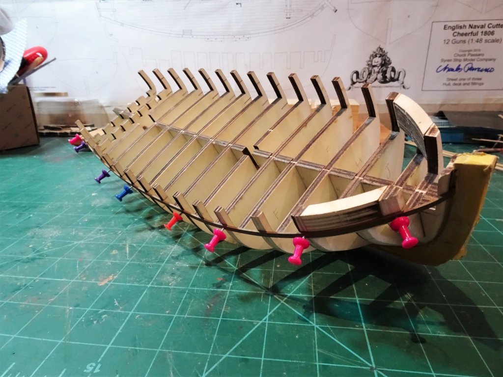
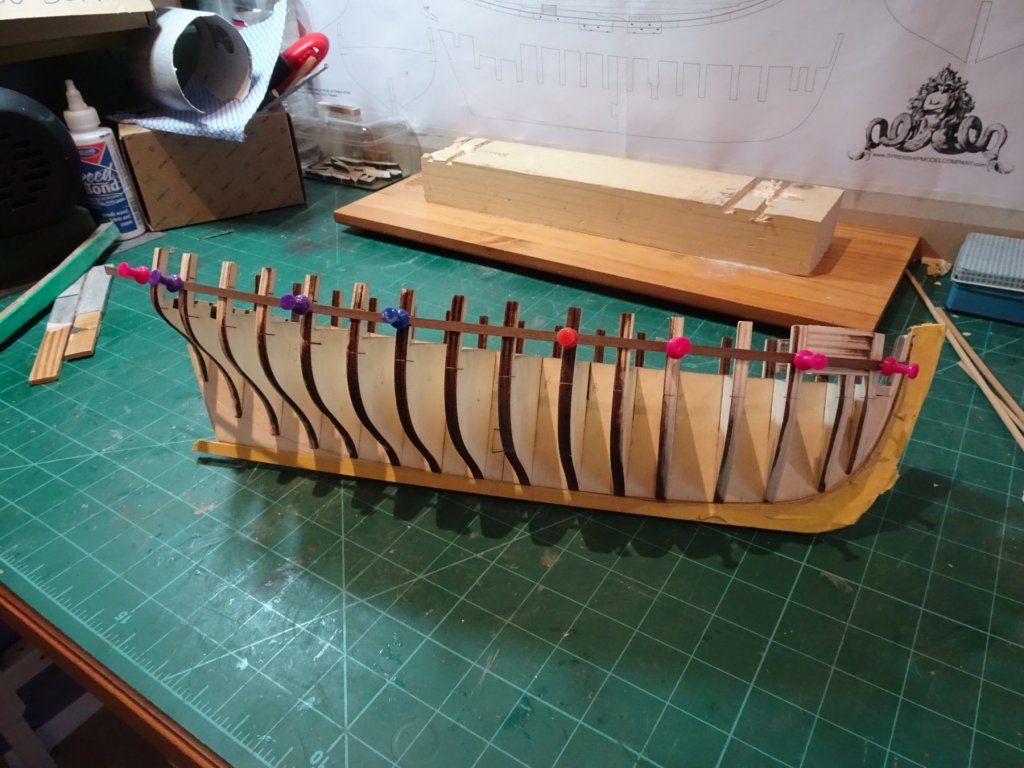
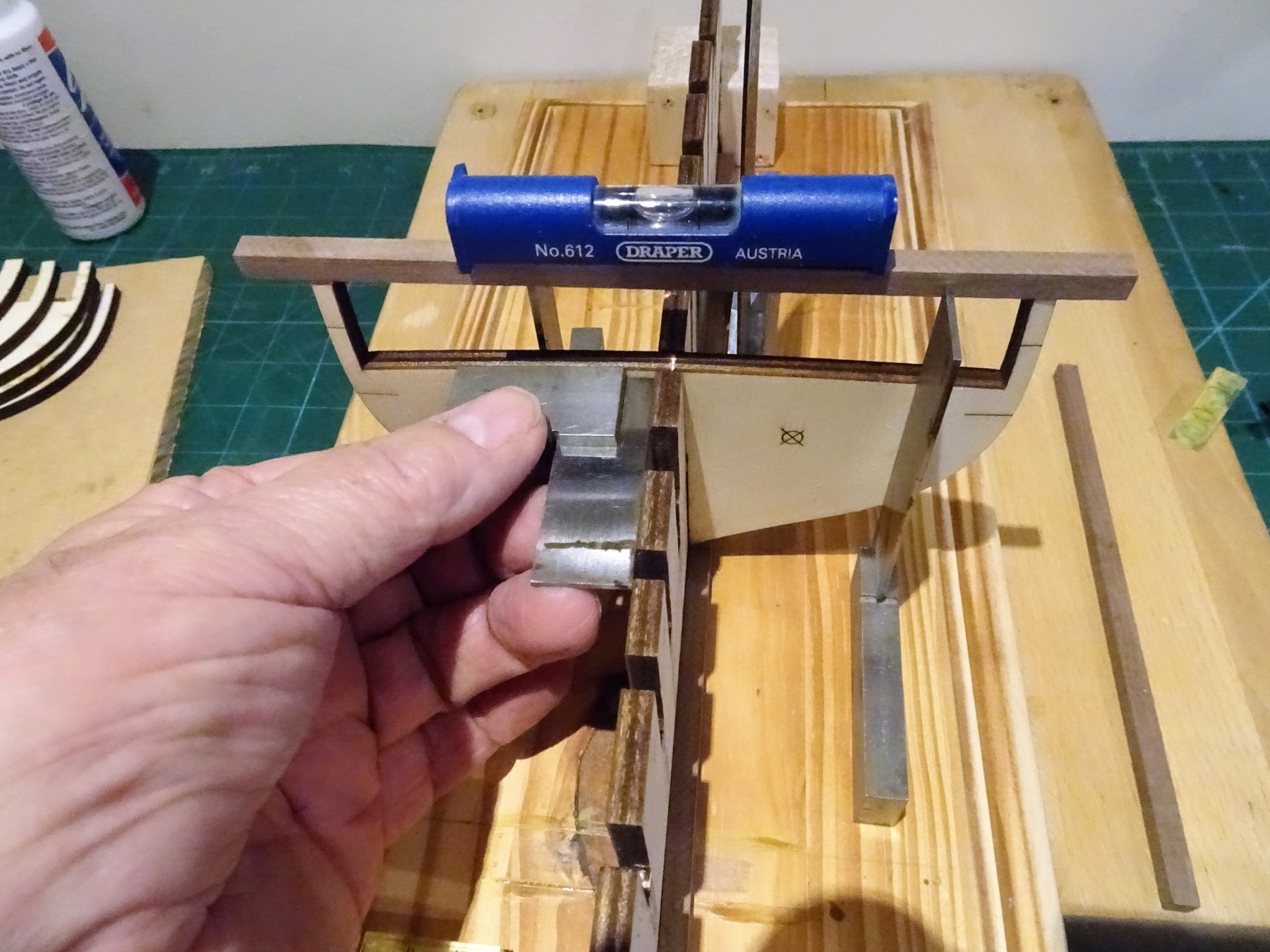
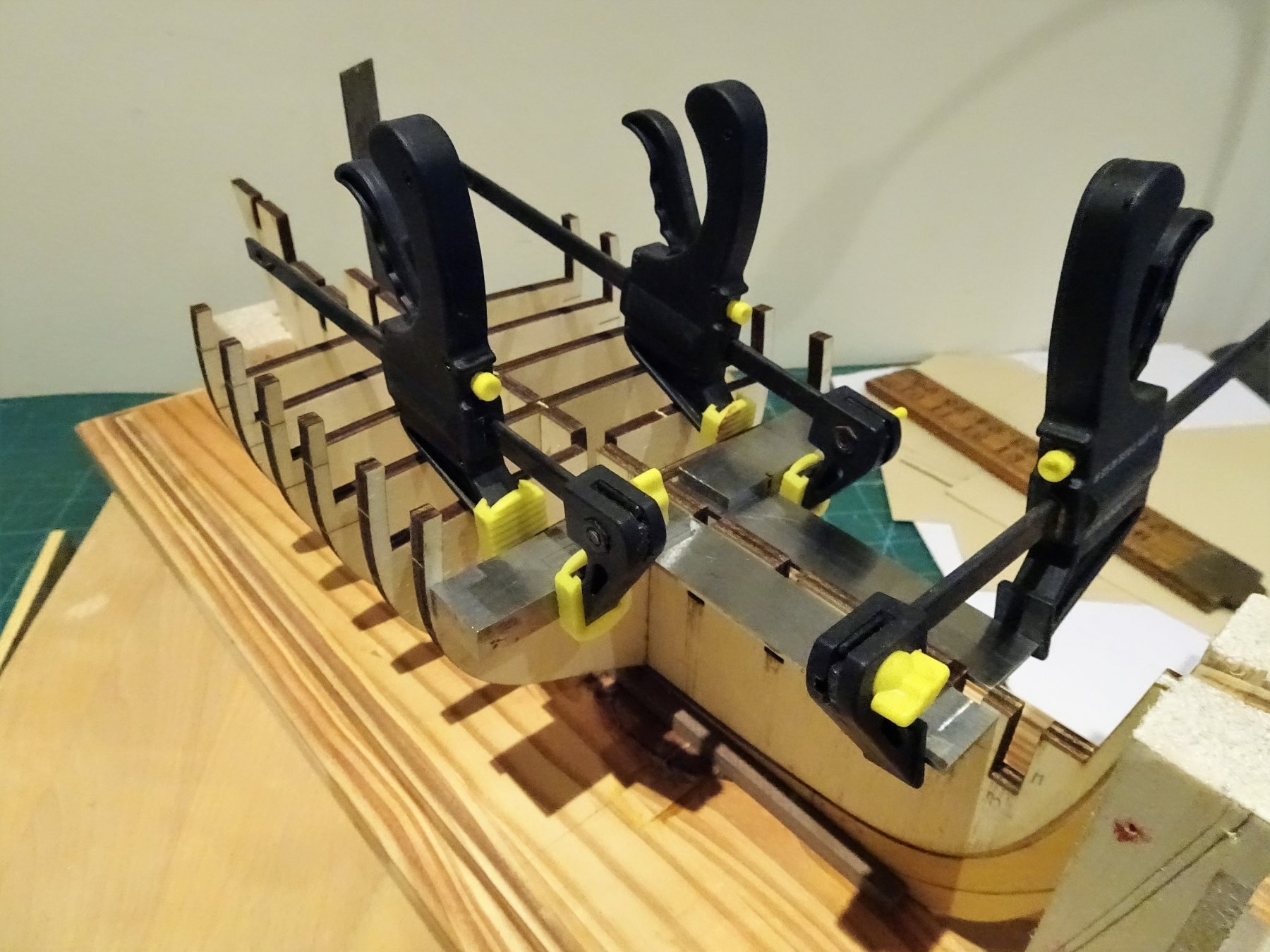
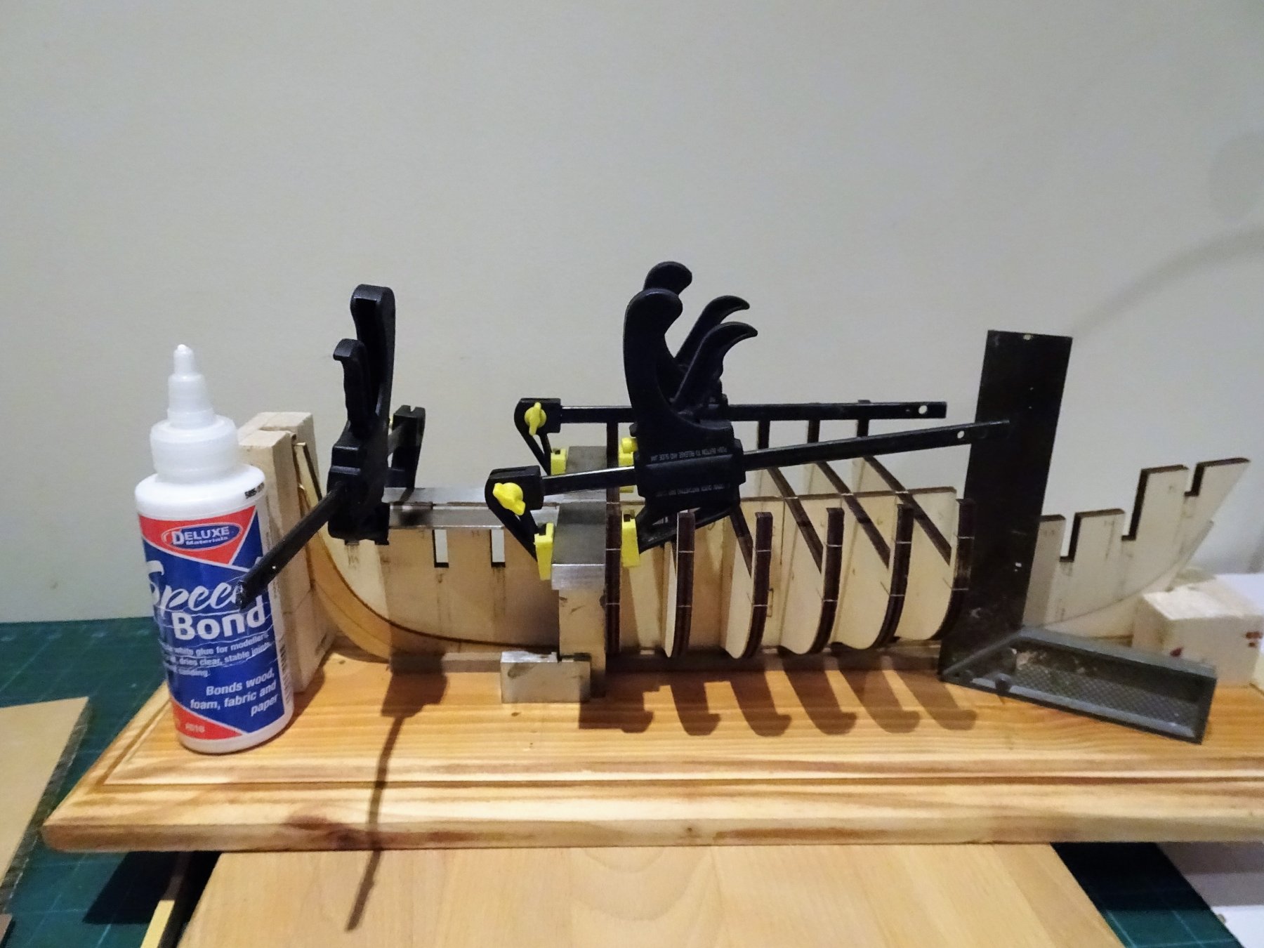
Post 5 Bulkheads. Nice to have these heavy cleanly cut bulkheads provided for me, I particularly like the scored reference lines for the ports and wales. All the Bulkheads slipped easily onto the false keel. 3820 At this point I made a simple support board to keep the keel upright whilst I fitted the bulkheads. Bulkheads not glued at this stage. 3823 Get my first real impression of what a chunky little vessel she will be, lovin' it already. The b/h's should have the scored reference lines for the ports and wale facing either forward or aft depending on whether they are designated by letters or numbers. Forward for numbers, aft for letters. Chuck has confirmed to me that b/h ⊕ can be placed either way around. 3835 Starting with b/h ⊕ I work fore and aft to glue them into place, checking for square and level as I go. 3837 3839 I use a high quality pva for this purpose, which has a 5 minute grab, sufficient working time, but short enough to hold quickly once positioned. With the bulkheads fixed it remains to fix the Bow and Port fillers. 3934 So far so good, then........ When it came to the Port fillers I hit a problem. The fillers run between the external edges of bulkheads J and M., leaving just a wedge of the shorter bulkhead L protruding, which will be faired away. 4013 On the starboard side of my cutter they fit perfectly, as above. ...but on the Portside seem a tad short. Hhmm have I got either Bulkheads J or M slightly out of square, I spent so much time squaring them up, or has a bit of warp crept into the bulkhead. Annoying and barely a mm but sufficient to need a filler to make up the difference. Rather than try to get the bulkheads off again and perhaps end up with more trouble I added a sliver of Boxwood to the aft end of the filler pieces. 4008 To bring the filler sets up to the level of the Bulkhead extensions I split a spare filler piece and used one thickness of ply. 4012 Onto the far more testy business of fairing next. B.E.


- 574 replies
-
- 19
-
-
- cheerful
- Syren Ship Model Company
- (and 1 more)
-
That is from a painting by John Dews the Yorkshire Marine artist, depicting the Sir Winston Churchill off Whitby. She is wearing the Flag of St George, the English Flag. As she is not a naval vessel, where the flag and position may have more relevance, it may simply be indicative that she is an English ship. At the stern she wears the Red Ensign, of the British merchant marine. B.E.
-
Hi Paul, I didn't coat the plates I wanted them to gain a natural patina over time. I was careful when handling the model not to touch the plates with my bare hands. Cheers, B.E.
- 366 replies
-
- 2
-
-
- pegasus
- victory models
- (and 2 more)
-
She's coming together very nicely Lukas. B.E.
-
Cheers mobbsie, Whatever the limitations of the Proxxon machines I have are, at my skill level I doubt I will ever test them. Best wishes to you and yours for Christmas and the New Year. B.E.
- 574 replies
-
- 3
-
-
- cheerful
- Syren Ship Model Company
- (and 1 more)
-
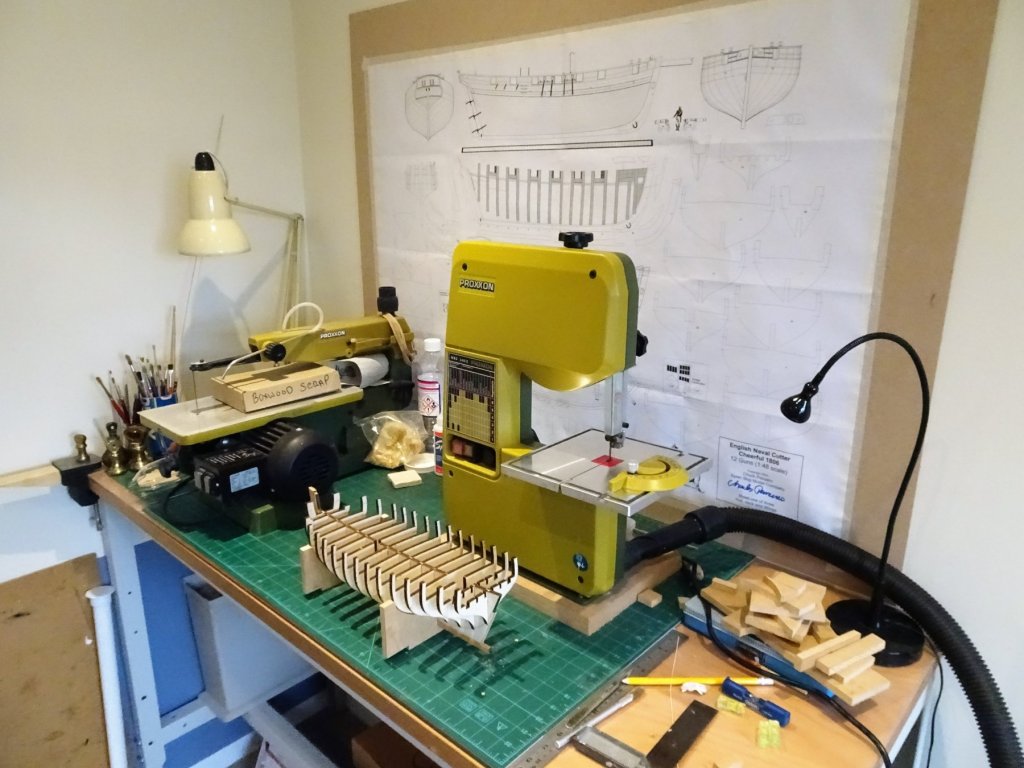
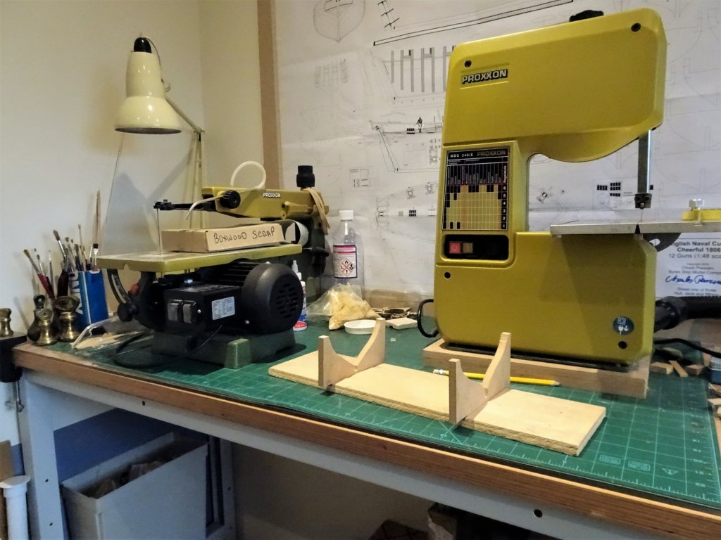
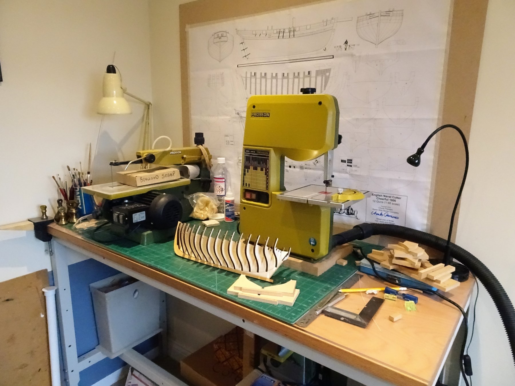
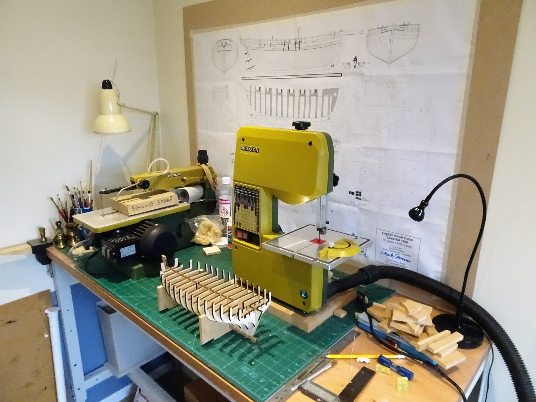
.....and necessary I think Michael to support the hull whilst working. I will end up with three different supports, the one above, one that holds the keel, stem, and stern in a fixed position, and a third that supports the hull inverted. I used the Band saw because the material was quite thick at 9mm but the curves were relatively gentle which the Band saw could handle. I also find that the more rigid blade allows me to cut straight lines freehand better than the scroll saw. The downside is that the Band saw is quite noisy compare to the scroll saw. B.E.
- 574 replies
-
- 5
-
-
- cheerful
- Syren Ship Model Company
- (and 1 more)
-
Don’t know how one can fair those fragile bulkheads without bracing strips, but once in place you can proceed with confidence. Still need soft hands tho’. 😉 B.E.
- 90 replies
-
- 4
-
-
- english pinnace
- Finished
- (and 1 more)
-
I’m late to this party Peter, not quite sure how I missed it. You’ve taken on quite a beast, and made a lot of progress in what seems to me to me a very short time. Nice idea to use ‘false port’ gun carriages, will give a far more authentic look. I’m not a fan of dummy plug in gun barrels. B.E.
- 366 replies
-
- 4
-
-
- bellerophon
- victory models
- (and 2 more)
-
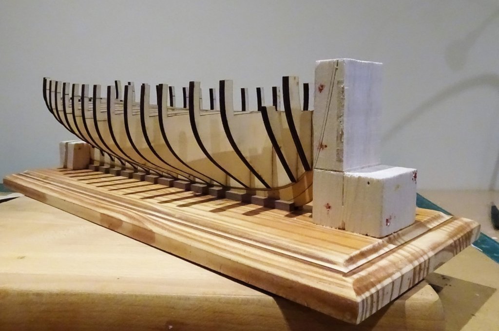
Thanks Martin, been 2013 since we had any significant snow in my small area of England, an area that would no doubt slip into a corner of Oklahoma and not be noticed for weeks. Great for taking seasonal pictures of William, but it's all gone now. Been busy in the shipyard this morning making an additional support cradle for the Cutter. 3927 Haven't used it for months but the Band saw came into its own today, I so love these bijou Proxxon machines. 3932 Set the supports for bulkheads H and 8. 3933 Rough and basic from a bit of scrap 9mm mdf, but it will serve the purpose. Winding operations down now for the Christmas break. 2659 Not before time for some of the Dockyard workers. Cheers, B.E.


- 574 replies
-
- 18
-
-
- cheerful
- Syren Ship Model Company
- (and 1 more)
-
Hi Chuck, I am just about to start fixing the bulkheads on my version of Cheerful, and I am mindful of your warnings about ensuring that the scored reference lines on the bulkheads face forward for numbers and aft for letters. This is probably a stupid question but which camp does bulkhead Ø fit into - numbers or letters? I have trawled thro' some of the build logs and there seems to examples of both. Regards, B.E.
- 1,051 replies
-
- 3
-
-
- cheerful
- Syren Ship Model Company
- (and 1 more)
-
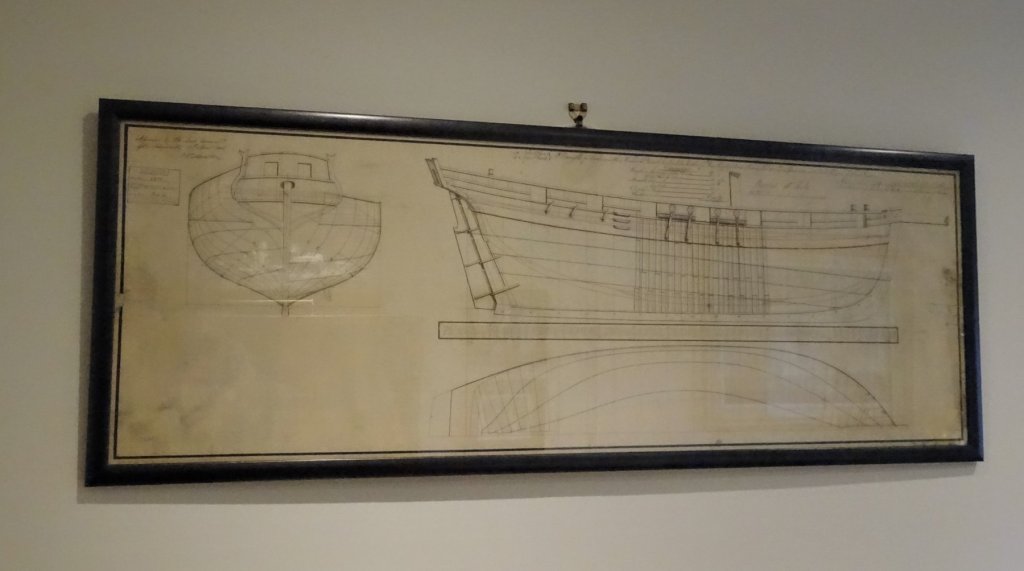
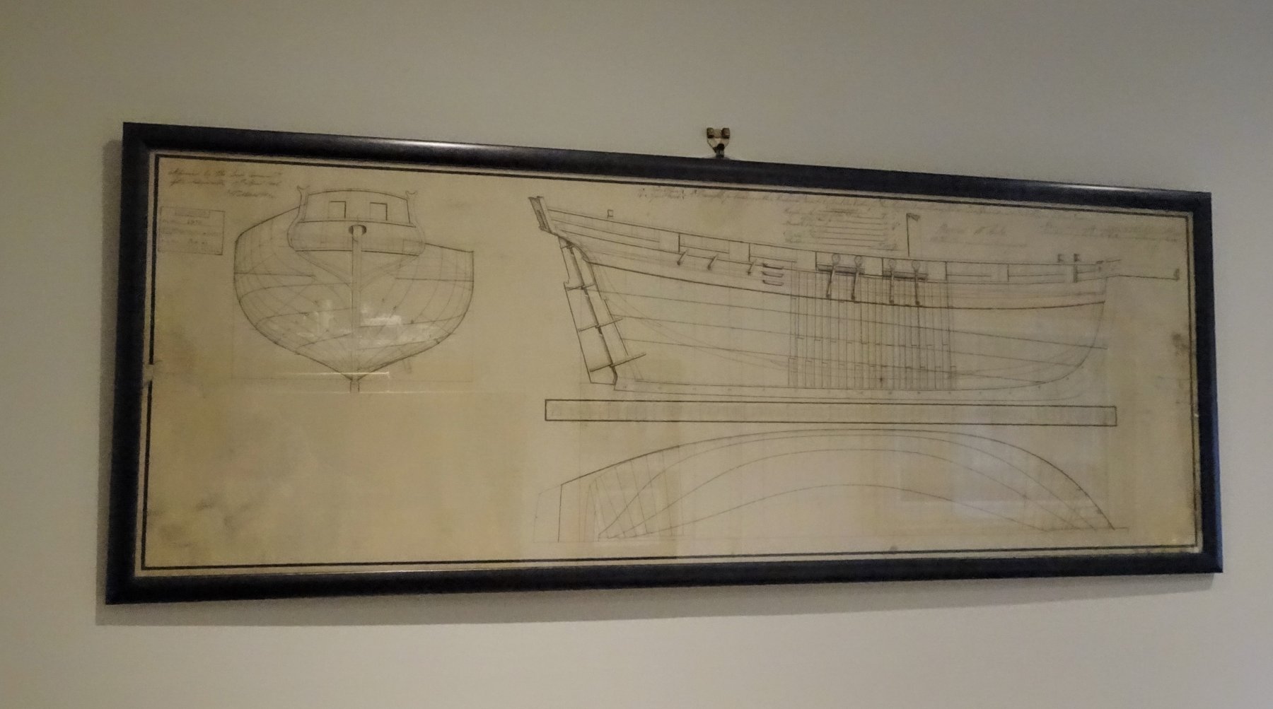
Thanks Martin, I can't make out the signature on the plan but this is what I know. Cheerful (and Surly) were designed by Sir John Henslow, Surveyor of the Navy, who had served as a young man as draughtsman to Sir Thomas Slade; The Cheerful Class were the last of a varied class of ship designs produced before he retired in 1806. The plans were produced in The Navy Office 16/4/1806, approved by the Lords Commissioners of the Admiralty 17/4/1806 and a copy of the draught sent to the Merchant Builders James and Joseph Johnson, Dover 30/5/1806. The keel was laid in June of that year, the vessel launched in November, and commissioned in January 1807. She was sold on 31 July 1816 after 9 years service. Surly her sister ship was commissioned at the same time but had a much longer and more exciting early career, finally sold in 1837 after some 30 years. The moral of this tale if anything, is, if longevity is your goal, it's better to be surly than cheerful. Happy Christmas to you and Mrs W. B.E.

- 574 replies
-
- 14
-
-
- cheerful
- Syren Ship Model Company
- (and 1 more)
-
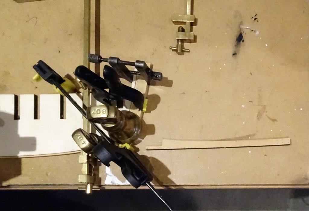
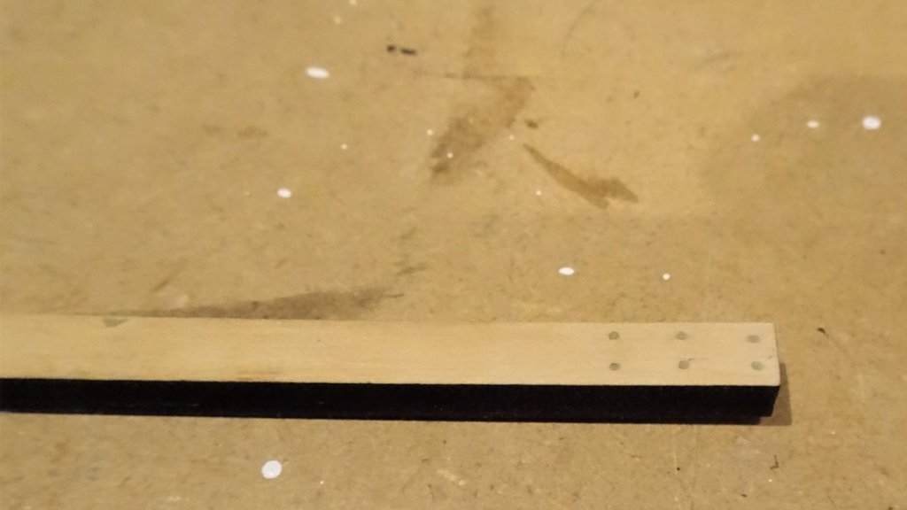
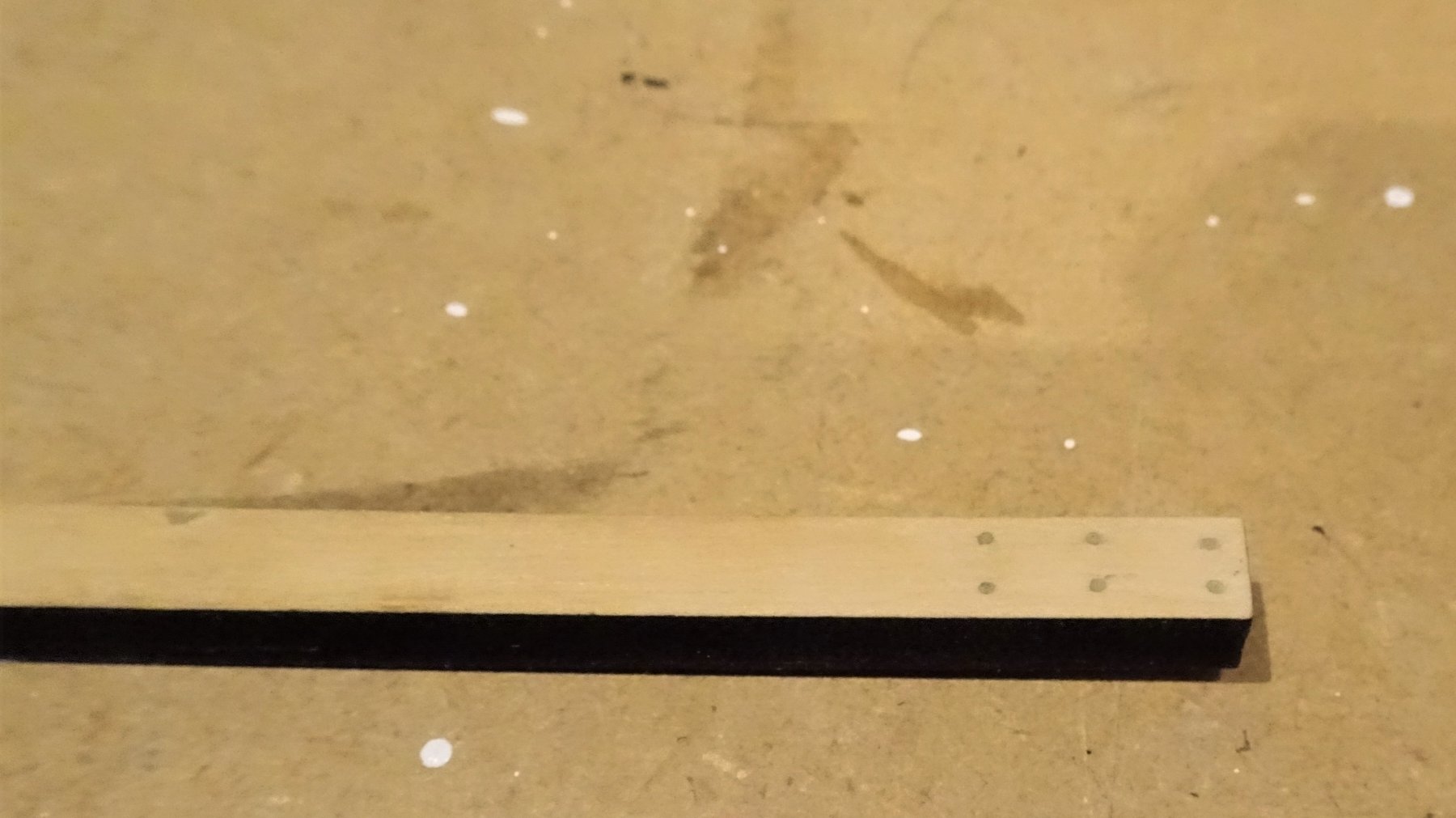
Post 4 Attending to the stem I am grateful to Chuck for the laser cut parts that make up the stem and keel, saves a lot of time faffing around with the scroll saw; nice Boxwood and need for very little fettlin', the most time consuming part is removing the quite heavy char on the pieces. I did this mostly by scraping with a sharp blade. I followed Chuck's example of filling the treenail holes rather than use dowel pegs. 3772(2) 3609 They are very small, he suggests a #76 drill equivalent to 0.508mm Ø I used a 0.6mm Ø drill. 3603 Once I was satisfied with the fit the two stem pieces were glued together. 3608 and then to the Rabbet strip on the false keel. 3772 All went together very nicely. 3774 The two keel pieces were then added. 3779 Impressed by the fit of the stern post and rudder, although these will be put aside for much later in the build. 3776 There seems to be a slight kink in the forward section of the keel, I hope this doesn't prove to be troublesome, the false keel looks true sighting along from stem to stern. To complete this part of the build, a light sanding and sealing with wipe-on-poly. 3786 3783 Note: Chuck makes reference to the use of Minwax wipe-on Poly to seal the Boxwood finish of the stem pieces once they have been fitted. For those in the UK Minwax products are horrendously expensive (£36) for what is essentially a thinned down oil based Polyurethane Varnish. Normal oil based Poly is readily available in the UK. Thin it down 50/50 with White spirit to make your own wipe-on. I used Blackfriars satin poly - 250ml cost me £8 effectively 500ml once diluted. There is loads of stuff on making your own w-o-p on the internet. 3771 Finally as with Pegasus I obtained the Admiralty plan for Cheerful and Surly which now sits above my workbench as additional inspiration. Next up fiddlin' with my Bulkheads. B.E.

.thumb.JPG.bf9d40161cde416403fcebd0c27ff8a1.JPG)


- 574 replies
-
- 23
-
-
- cheerful
- Syren Ship Model Company
- (and 1 more)
-
Good to see some progress Martin, I found drilling the hawse holes a testy moment in the build, something that stuck in my mind even tho' the detail of my approach had faded, and I had to refer to my log (page 3) This is what I wrote at the time: Hawse holes and bolsters This is a good time to attend to this job before other stuff gets in the way . The Hawse holes are 10½” ø equating to 4mm at scale (ffm). The anchor cables are 13” circ = to 1.65mm ø. A formula exists for determining the size of the hawse holes; diameter of cable x 9/4 = 3.7mm. Always best I think to start small and work up. The task of positioning the hawse holes and bolsters proved quite tricky and somewhat tense with the risk of a slip with the Minicraft drill. Even so little bits flaked off from the surrounding planking, and I could feel my stress levels rising until I had the four holes completed. Not too sure about the kit arrangement or the shape of the Hawse bolsters (120). I don’t want them fouling the lower/ekeing rails and I suspect that the kit set up is too far in towards the stem, and that the two holes are too far apart. Hope this helps rather than confuses. B.E.
- 467 replies
-
- 3
-
-
- fly
- victory models
- (and 1 more)
-
Nice progress Jason, very pleasing to my eye. B.E.
-
Having just looked at Rusty's completed Cheerful, two come along at the same time. What a stunning model you have created Mike, beautiful work, and another fine reference for those who follow on. Thank you, B.E.
- 452 replies
-
- 6
-
-
- cheerful
- Syren Ship Model Company
- (and 1 more)
-
Beautiful model Rusty, and great photo's. Fills me with some trepidation as I start out on my own Cheerful journey, but relieved that I have such an example to inspire me. Just one curiosity, why did you display the Union flag at the Gaff, rather than a naval ensign? beautifully fashioned flag by the way. Regards, B.E.
- 310 replies
-
- 2
-
-
- cheerful
- Syren Ship Model Company
- (and 1 more)


.JPG.f15d0bc5f77020035e647f23e3b6393c.JPG)