HOLIDAY DONATION DRIVE - SUPPORT MSW - DO YOUR PART TO KEEP THIS GREAT FORUM GOING! (Only 68 donations so far out of 49,000 members - Can we at least get 100? C'mon guys!)
×
.JPG.ca33079f5815b861e67b9c2cccd37982.JPG)

Blue Ensign
-
Posts
4,564 -
Joined
-
Last visited
Content Type
Profiles
Forums
Gallery
Events
Everything posted by Blue Ensign
-
 Cheers Kurt, I'm well acquainted with Chuck's magic hairdryer method, use it all the time. What an asset he is to us ship modellers. I've been thinking ahead today about the False Deck and I realise that I don't have the material for this as yet. Chuck used 1/16" Basswood sheet which would need to be some 6" wide x 16" long. We don't have such sizes in the UK readily available, although 1.5mm x 100mm x 1000mm sheets are. Looks like at least over here I will have to glue two sheets together to form the false deck, not really a problem, and I will have the centre line clearly marked. Cheers, B.E.
- 574 replies
-
- 3
-

-
- cheerful
- Syren Ship Model Company
- (and 1 more)
-
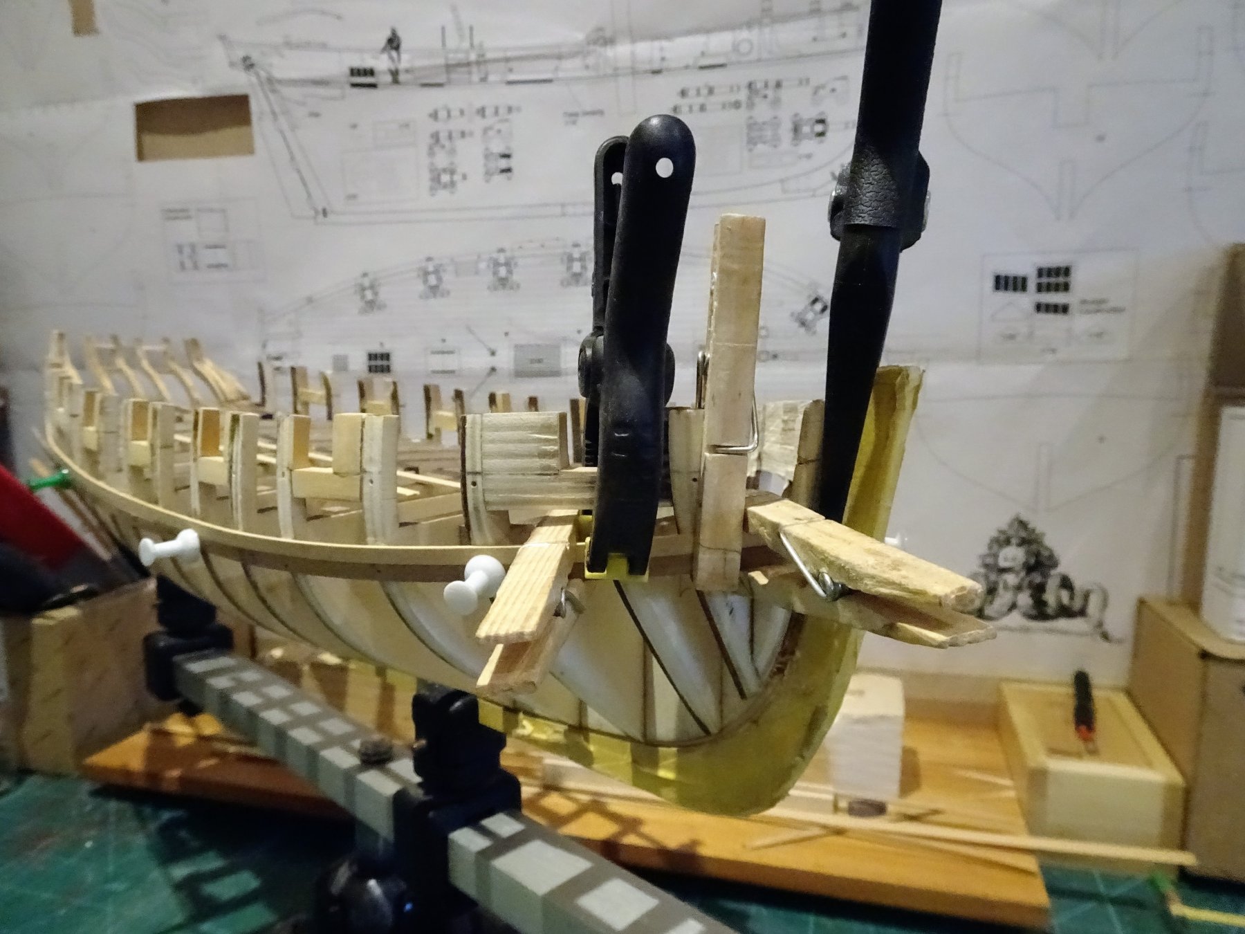
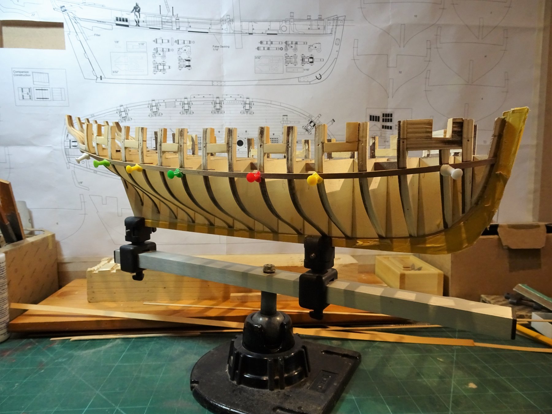
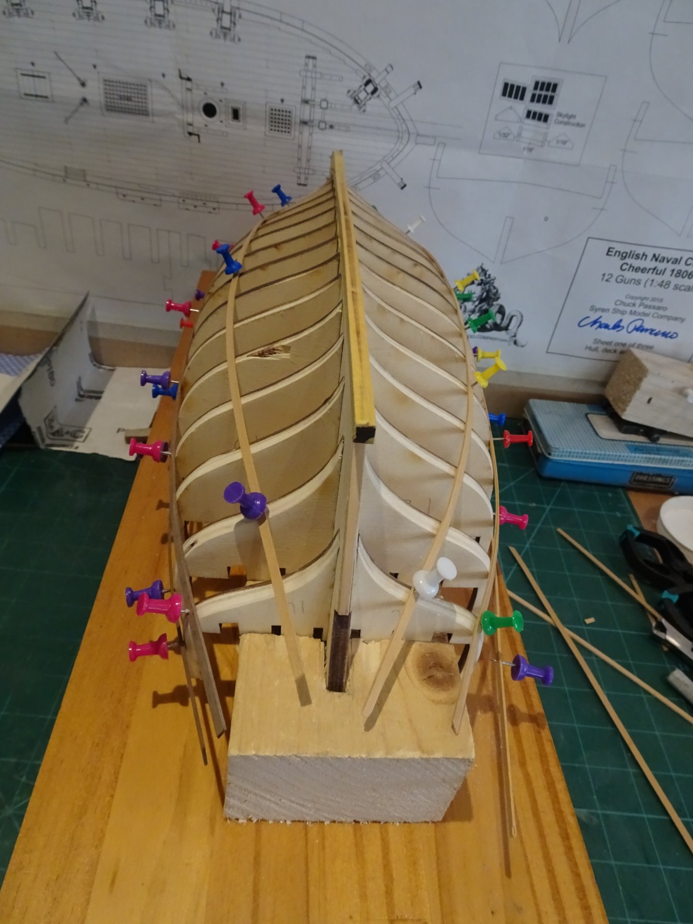
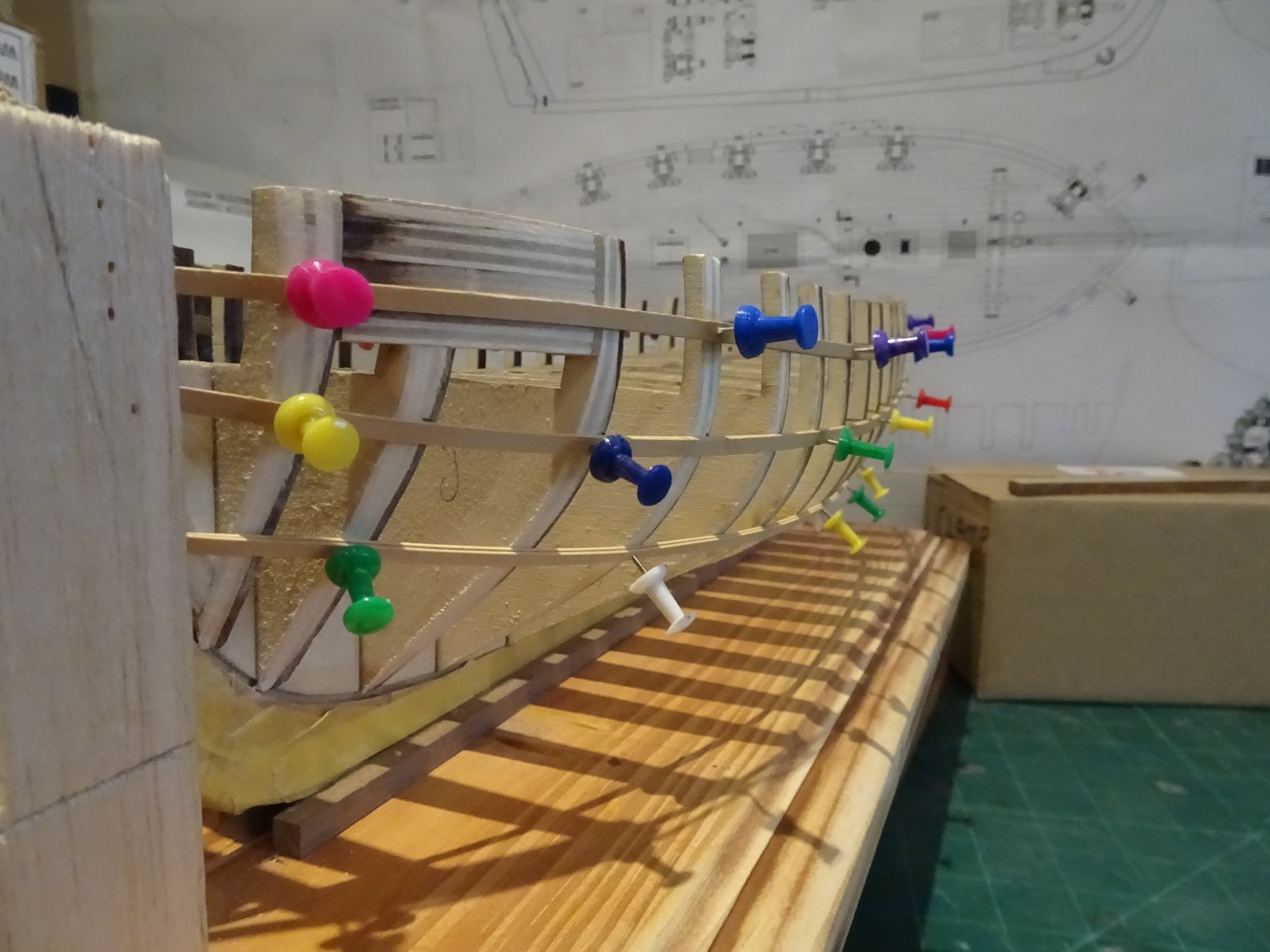
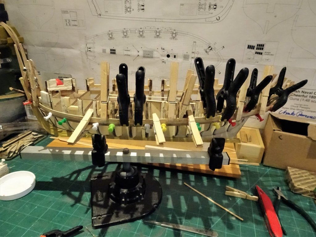
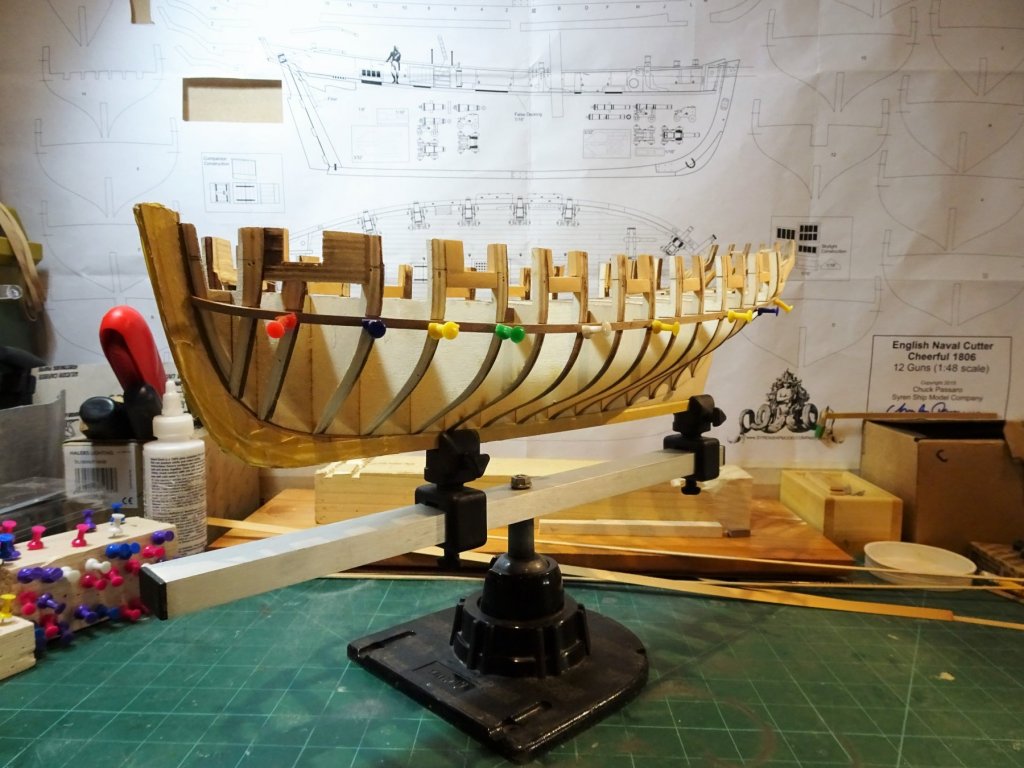
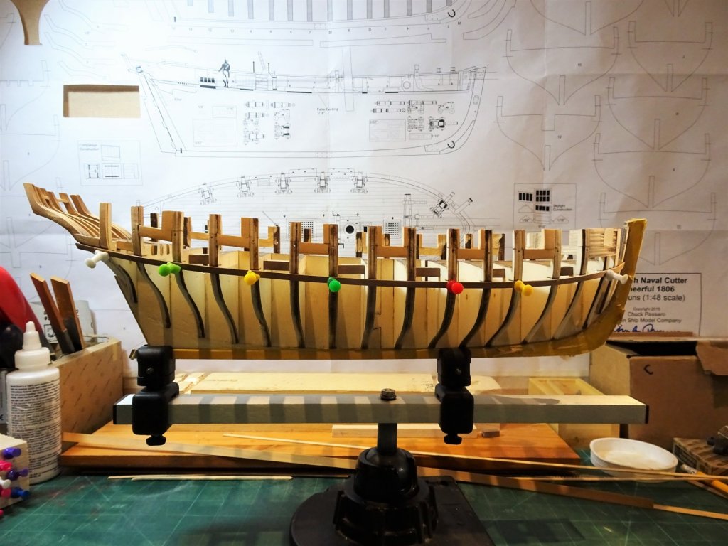
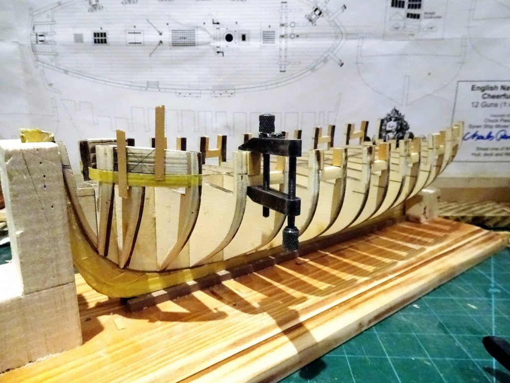
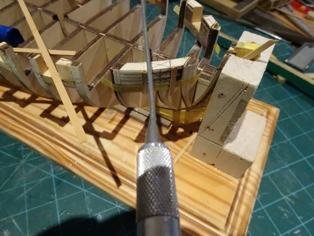
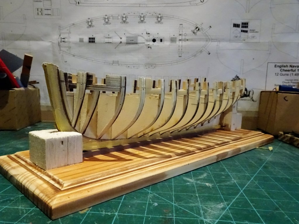
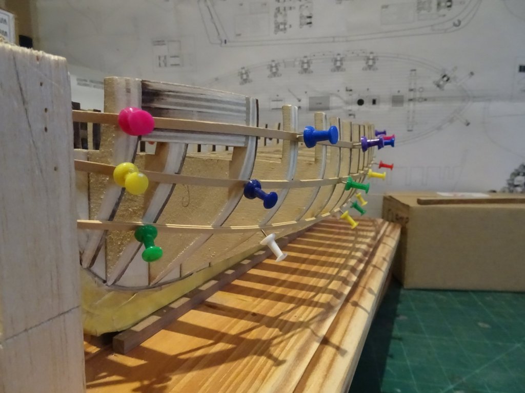
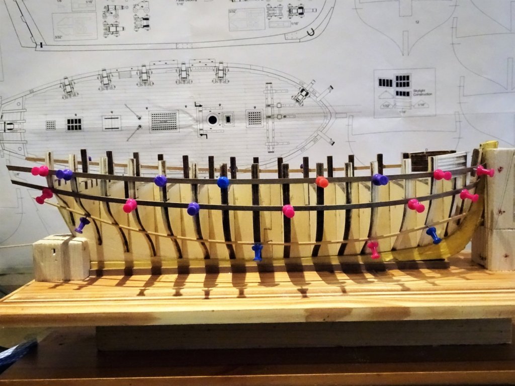
Post 13 Fixing the Wales The 5/32" x 3/64" milled Boxwood Strips provided by Jason, are a pleasure to work with. 5002 The forward end was given a little water/heat treatment to impart a tension free curve around the bow, but along the sheer the strips sat down on the guide strip without much pressure. 5062 I left the guide strips in situ during fixing the lower wale strip which I found to be useful. The push pin heads held the wale strip close to the bulkheads whilst the glue set, and wooden pegs held the strip down tight on the guide. 5069 The second upper layer of the wale is added. 5124 5125 5122 5121 5119 Paint considerations At this time painting around and inside the gun ports is suggested, mainly I suspect because once the moulding strip below the ports, and the bulwarks are planked, painting the small rebate around the ports without marring the Boxwood would be difficult. This doesn't fully address the issue tho' as I can imagine there will need to be a fair bit of touching up following the thinning down of the bulwark interiors. I have used the paint mix I used for my Long boat build to lay down an initial coat of paint, but doubt I have enough for Cheerful . These days I am always careful to make sure I have enough to finish the job when using a mix, something that has caught me out on a previous project. I've ordered a few paint samples to run a test, if I can find a ready mixed paint that fits the bill, all the better. B.E. 12/02/2018


- 574 replies
-
- 22
-
-
- cheerful
- Syren Ship Model Company
- (and 1 more)
-
A lathe for masts and spars
Blue Ensign replied to Don Quixote's topic in Modeling tools and Workshop Equipment
Thanks Derek for the compliment, the Proxxon is a quality item and you can get a bed extension for it too. The Mantua is poor quality by comparison, and over priced (I have owned one). B.E. -
From one Ensign to another Gary, congratulations on completion of your Victory, a very fine model, very well done. B.E.
-
Thanks for your responses guys. Leaving the strip in place seemed a logical thing to do given the time spent getting the line right but as there had been no mention of doing this it set a doubt in my mind that there was some issue I hadn't considered. With the strip in place the boxwood 'proper' strip can be pressed down into position without having to watch for slippage below the line whilst gluing, and the guide strip can also be used to assist holding the wale strip in place. Only thing I can see as a possible problem is the risk of excess glue sticking the wale to the guide strip. I'll give it a go. B.E.
- 574 replies
-
- 4
-
-
- cheerful
- Syren Ship Model Company
- (and 1 more)
-
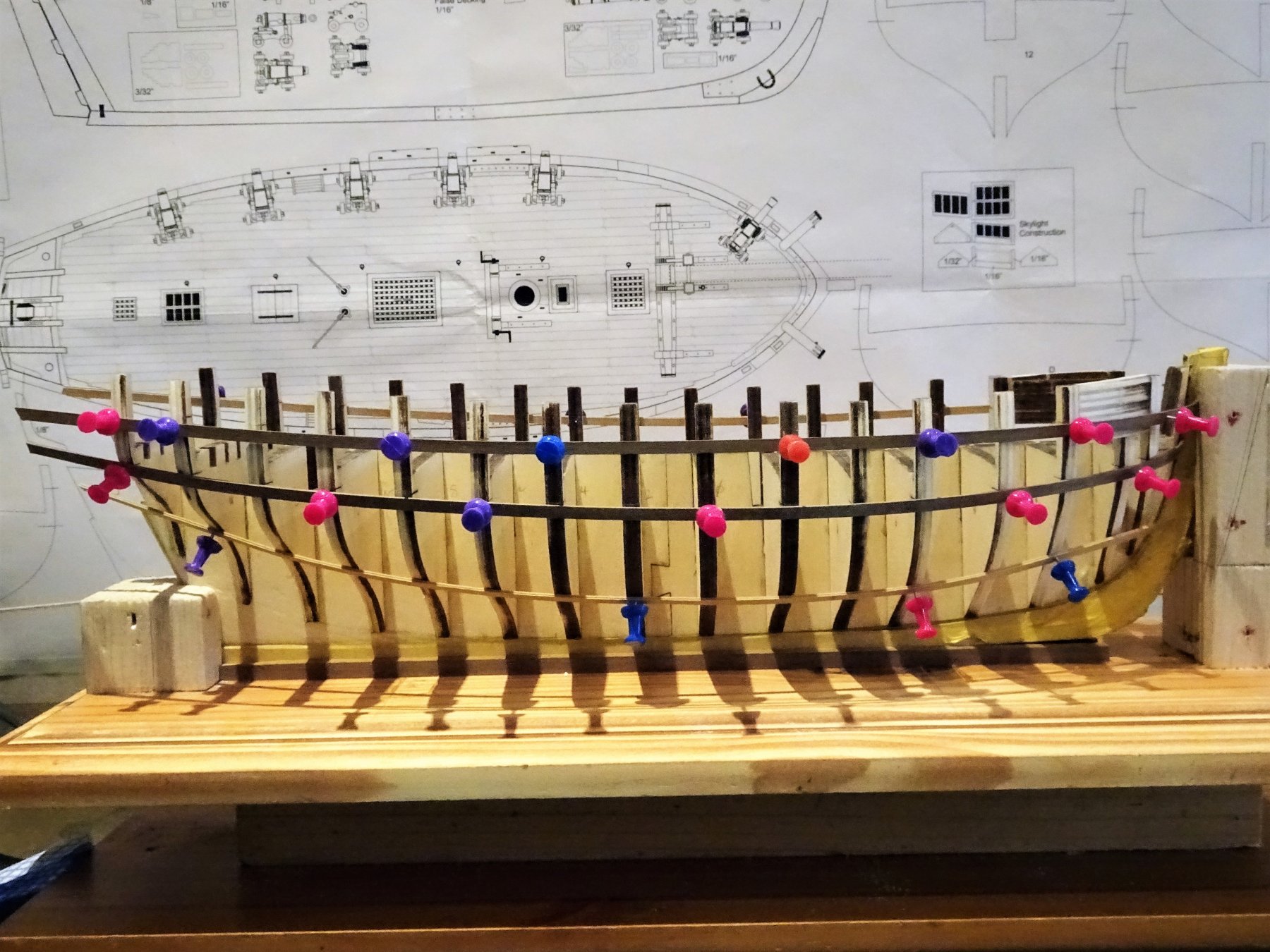
Post 12 Preparation for the Wale. To mark the lower wale edge I gave the trial strip a lateral curve using wet and heat, hoping to take some of the fight out of it when fixing to the bulkheads. 4973 4975 4976 It strikes me that this could be left temporarily in situ as a guide rail to fix the actual lower Boxwood Wale strip on top of it to follow the correct sheer. Any of my fellow Cheerful builders got any thoughts on this, any potential snags envisaged in following this approach? B.E. 07/02/2018

- 574 replies
-
- 13
-
-
- cheerful
- Syren Ship Model Company
- (and 1 more)
-
Thanks Kurt, I hope my build continues to hold your interest; my Pegasus build was seven years in the doing, although I did also fit in a French Seventy-four conversion during the build. Running out of model space now so I intend to take my time with Cheerful, but I don't think I will be able to resist Chuck's Royal Barge when it becomes available. B.E.
- 574 replies
-
- 3
-
-
- cheerful
- Syren Ship Model Company
- (and 1 more)
-
Kind of you to say so Derek, I'm glad my stuff has been of help to you. I haven't used either the planer or thicknesser very much yet, but they certainly have their uses on the model makers bench. The thicknesser is ideal for thinning down sheet and strip stuff when what you've got is just a tad too thick, but it is quite an expensive bit of kit. I have used the planer more, particularly for reducing square stuff to specific sizes and cleaning and squaring up stuff for scratch building. Much easier than trying to hand plane smallish lengths of timber. The Mill is a very useful tool, and I wouldn't be without it, but the machine I've used most is the scroll saw, wouldn't have liked to attempt the frames for the 1:64 scale Pinnace and Longboat for Pegasus without it. Cheers, B.E.
- 574 replies
-
- 3
-
-
- cheerful
- Syren Ship Model Company
- (and 1 more)
-
Good shots Kurt, I see I have some way to go to fair down the section of the outer stern frames between the last bulkhead and the Square Tuck piece. Your base layer wale looks good, I'll be pleased when that part is over. ps: do you have a log on the forum? B.E.
- 574 replies
-
- 2
-
-
- cheerful
- Syren Ship Model Company
- (and 1 more)
-
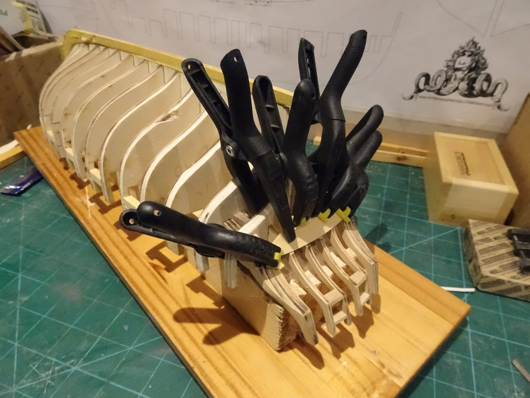
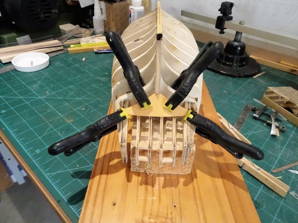
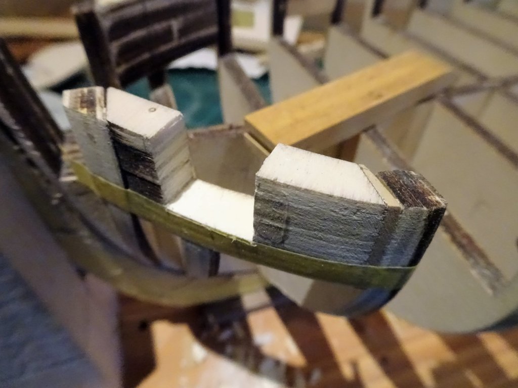
Those Stern ports are still niggling Kurt, other examples of cutters show a small aft platform covering the Rudder head on which stern chaser guns are mounted. There is an example of such an arrangement in The Naval Cutter Alert book by Peter Goodwin, showing a cutter model circa 1785 (The Science Museum) Still I've more pressing matters on my mind at present but I may return to the subject later. @ Mike, 'flawlessly' - if only Post 11 Square Tuck, and completion of Chapter Two. The Square Tuck piece was easily cut from 1/32" sheet Boxwood using a scalpel. 4830 I briefly wet the piece before clamping it in position overnight to give a bit of conformation and to take the stress out before gluing. 4834 Glued into place using pva. 4837 4842 There is a subtle concave shape to the Square Tuck piece once it is glued into place. 4873 A Balsa infill was placed behind the Square Tuck piece as indicated in the Instructions. Now the tricky bit, getting the formation around the two outer stern frames properly faired to take the wale termination, struggling a little to get my head around this at the moment. B.E. 03/02/2018


- 574 replies
-
- 13
-
-
- cheerful
- Syren Ship Model Company
- (and 1 more)
-
Very nice work Rusty, she's far too good a model not to restore. B.E.
-
Cheers Guys, Thanks Ian, that's a good idea re thinning the stern frames, one slip with the dremel could be very nasty indeed. @ Michael, I've wondered as well, are they supposed to fulfil the role as gun ports, how would guns fit and be secured, if not for guns what are they for? maybe things will become clearer later, I haven't really looked that far ahead. B.E.
- 574 replies
-
- 3
-
-
- cheerful
- Syren Ship Model Company
- (and 1 more)
-
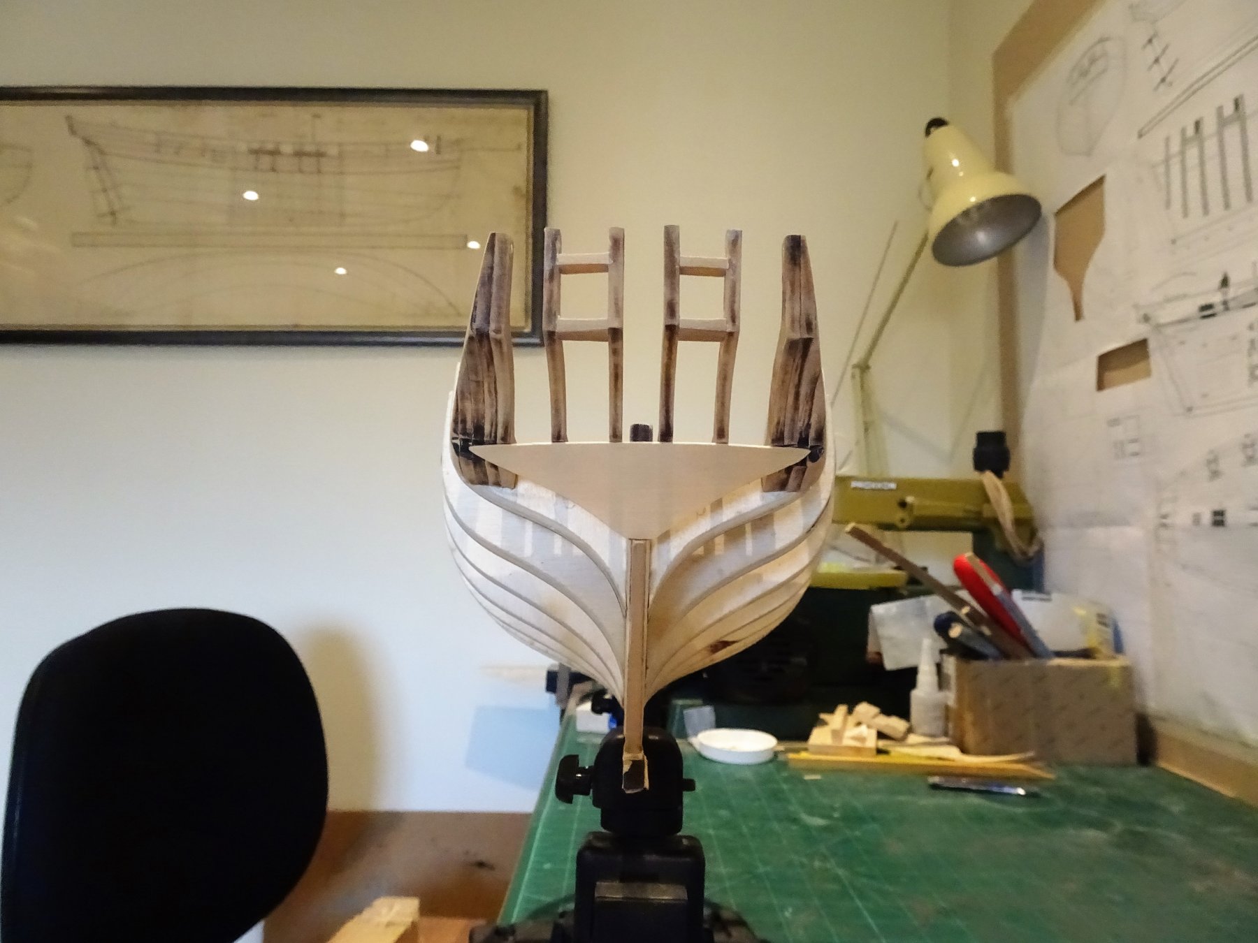
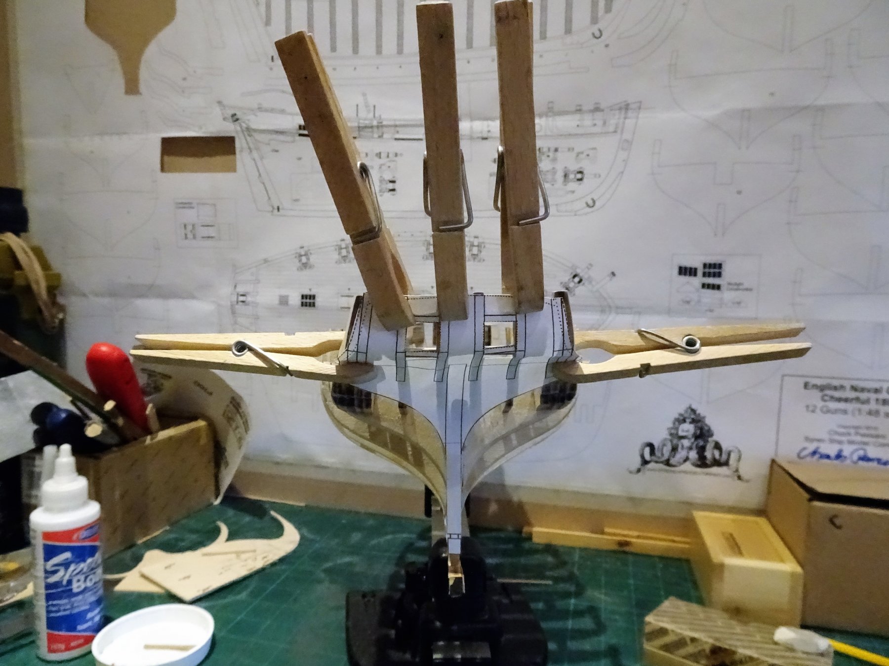
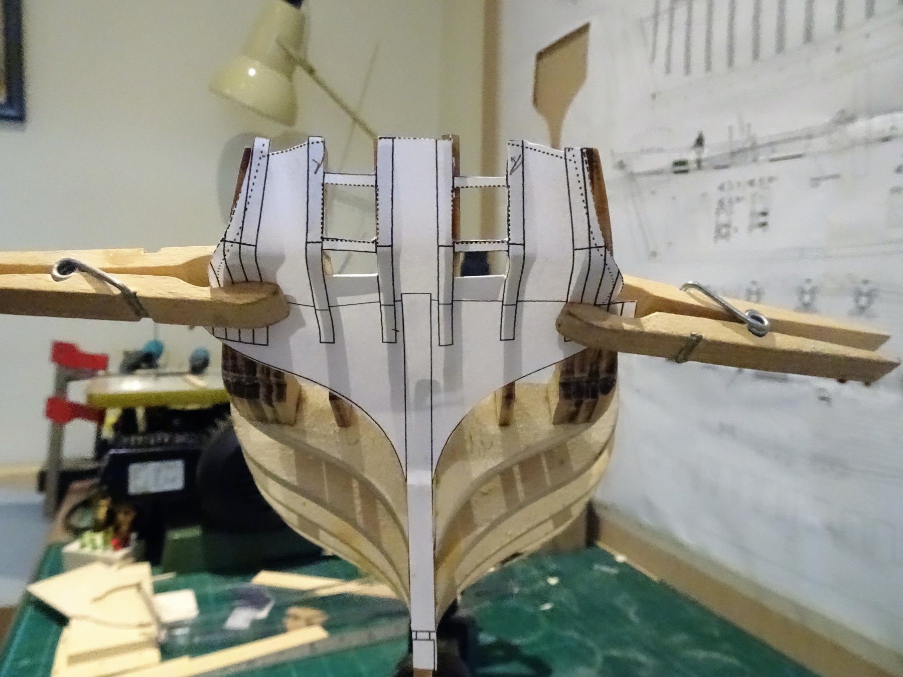
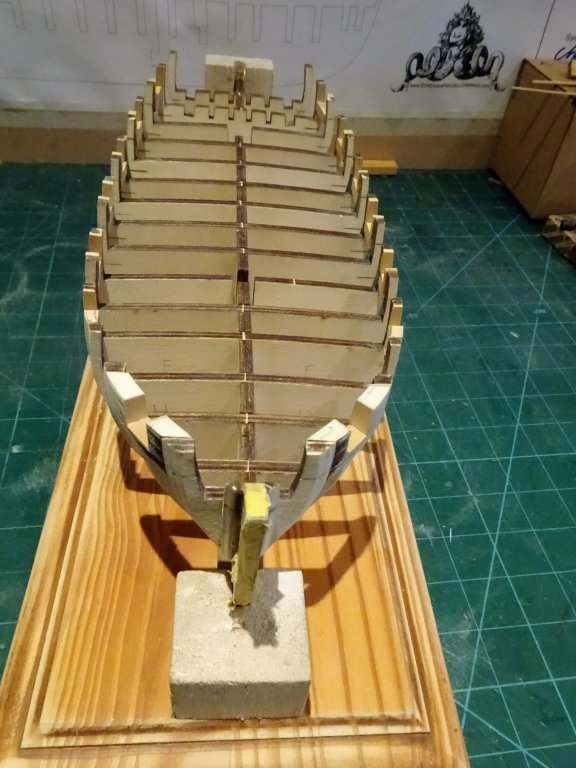
Post 10 Stern ports The prospect of doing these was quite daunting and I trawled all available logs for photo's and approaches before I started. My approach was as follows. I firstly cut the strips for the sills to fit snugly between the frames. 4676 Allowing for a small exterior over hang to take account of the transom curve, I marked the width taken from the plan, and cut it to size. I worked on the basis that the inner line was square to the frames and that the sill was level to the waterline. I fitted one and checked it against the plan. With the pva semi set on the first sill I added the second sill, and matched it to the first again using the plan as a guide. 4677 Checking the level of the sills. 4680 A section of 'port' sized wood was formed to get the position for the Lintels. This was done once the sills had set. The lintels were then cut to size and glued into place using the top of the port 'jig' as a guide. 4736 Both sills and lintels were then sanded to conform to the stern frames. 4820 The moment of truth, will the plan template fit. Not really a shot in the dark, I used several copies of the template to check progress as work progressed. 4819 Seems to fit fairly well. 4825 4827 4828 4829 Moving onto the Square tuck piece next, then back to a little more fairing and fine sanding. B.E. 31/01/2018


- 574 replies
-
- 19
-
-
- cheerful
- Syren Ship Model Company
- (and 1 more)
-
Hi Steve, of course there is modelling life without Proxxon, just takes much longer by hand, but I would hate to give up my scroll saw in particular. I do have the Crown wood set for Cheerful, but haven't used any as yet. I have a stock of old Boxwood that I've used thus far for the Port frames, and have some sheet stuff from :- http://www.originalmarquetry.co.uk/category_Saw_Cut_Veneers_3.htm I planked both Pickle and Pegasus using the Boxwood flat lines from the above company. Very useful 0.7mm thick strips in varying widths up to 10mm, and small square section stuff. Cheers, B.E.
- 574 replies
-
- 3
-
-
- cheerful
- Syren Ship Model Company
- (and 1 more)
-
Don't know what your golf handicap is Bob, but your ship modelling is pretty much off scratch Nice job on the ratlines. B.E.
- 682 replies
-
- 5
-
-
- halifax
- lumberyard
- (and 1 more)
-
A fine job Jason, and nice and close to the stern post. Will you be fitting a Rudder coat? B.E.
-
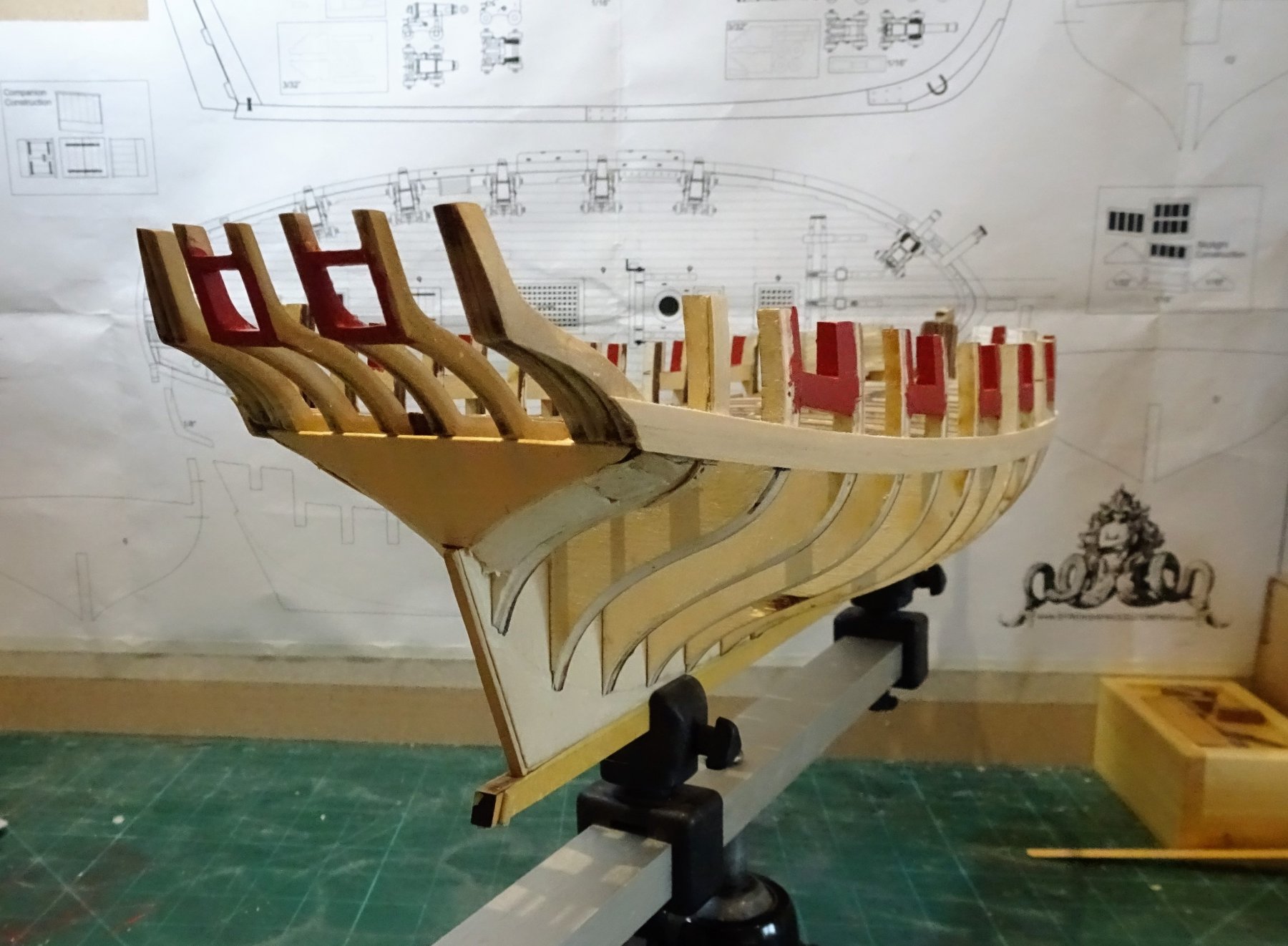
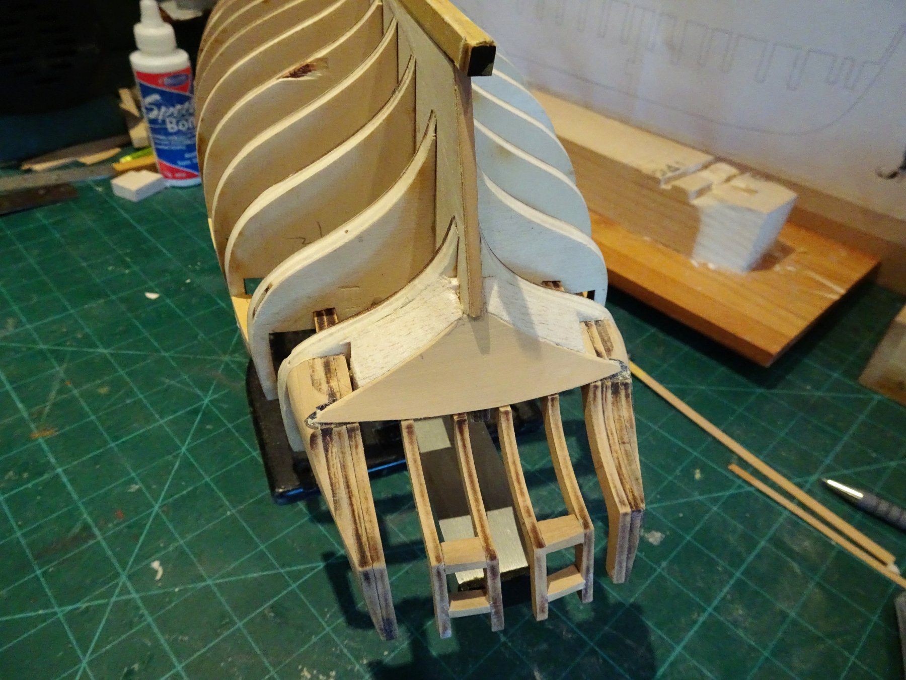
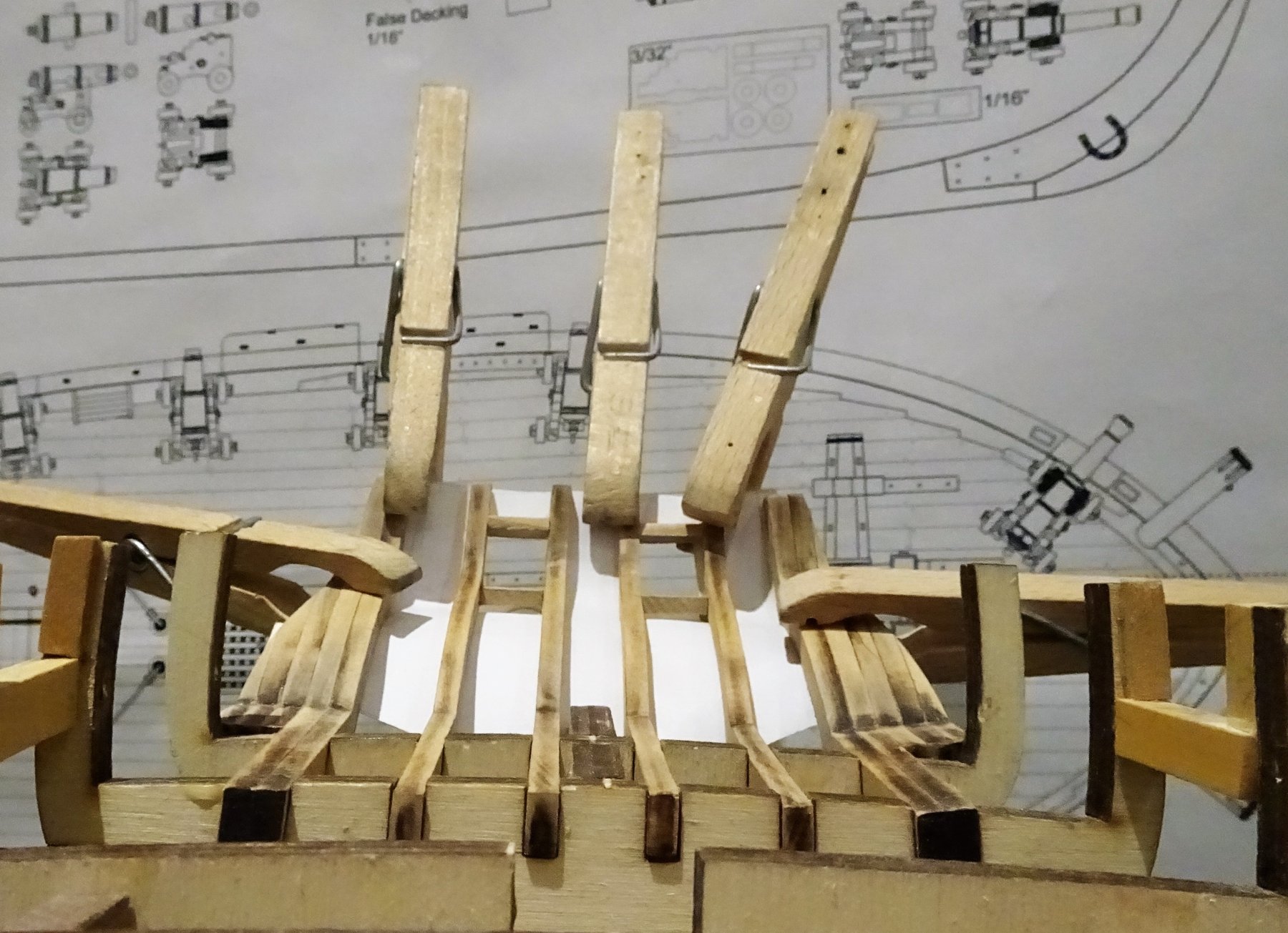
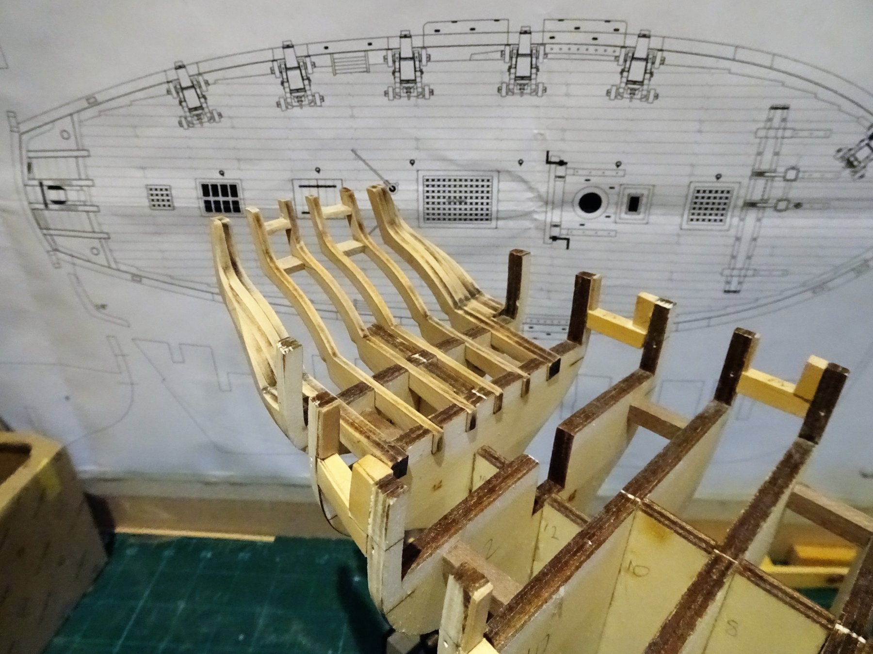
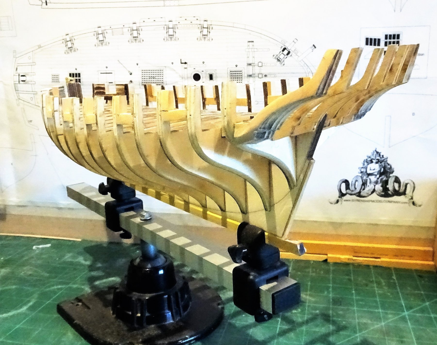
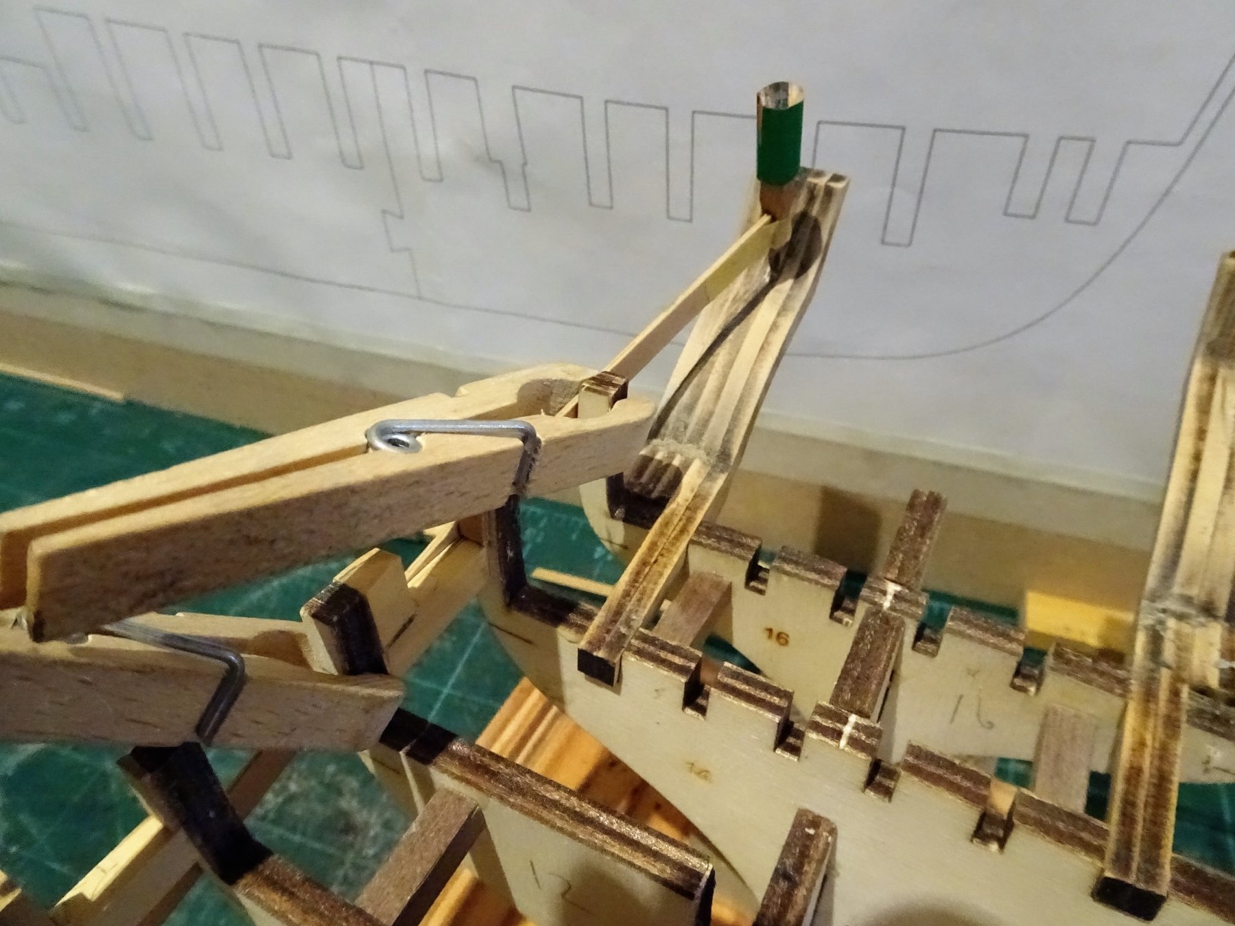
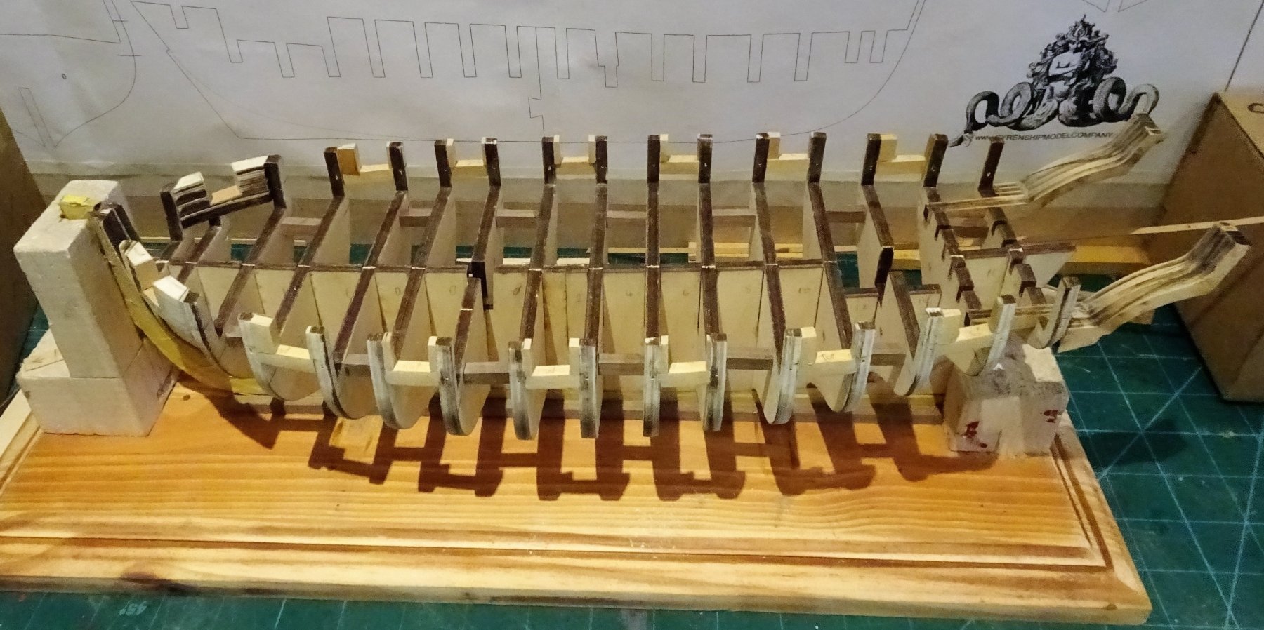
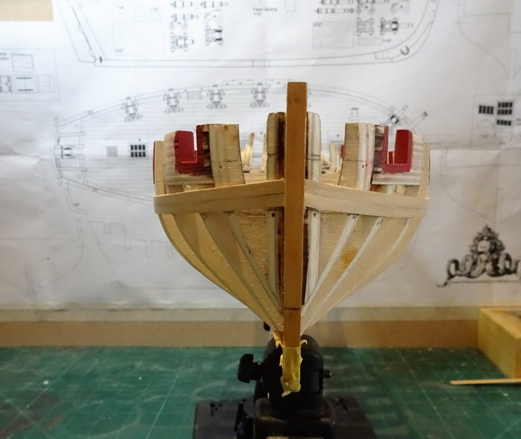
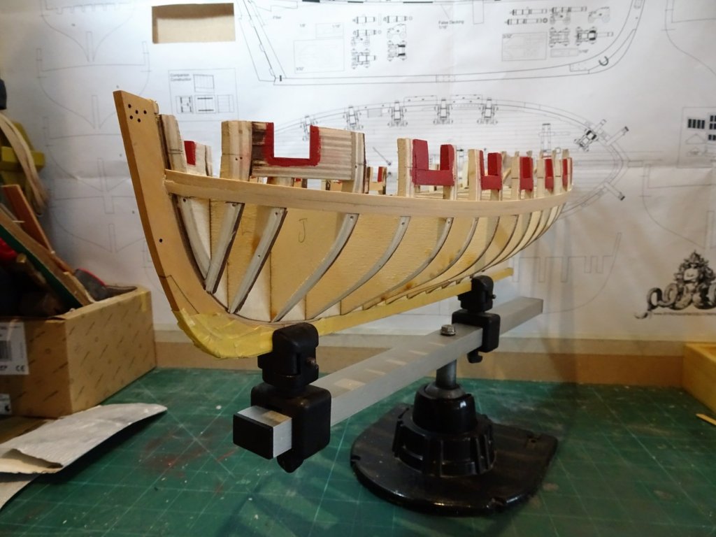
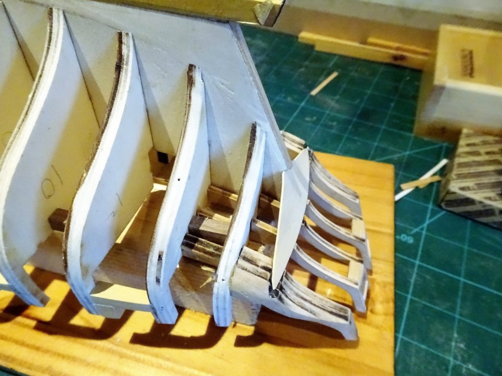
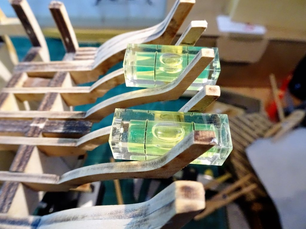
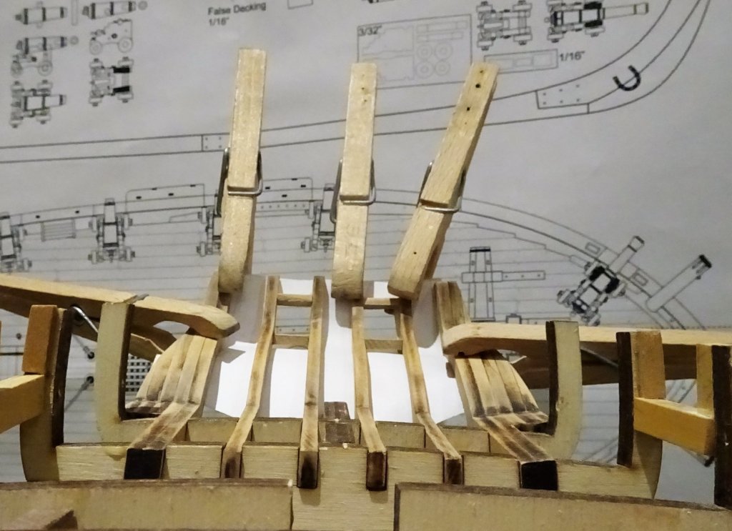
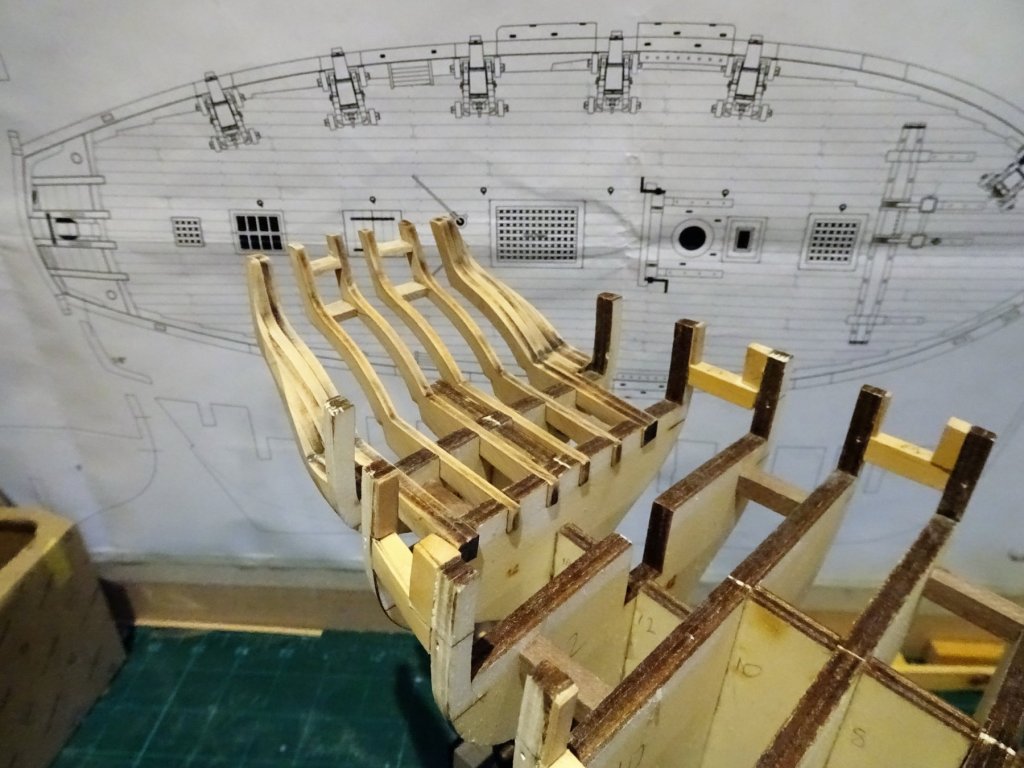
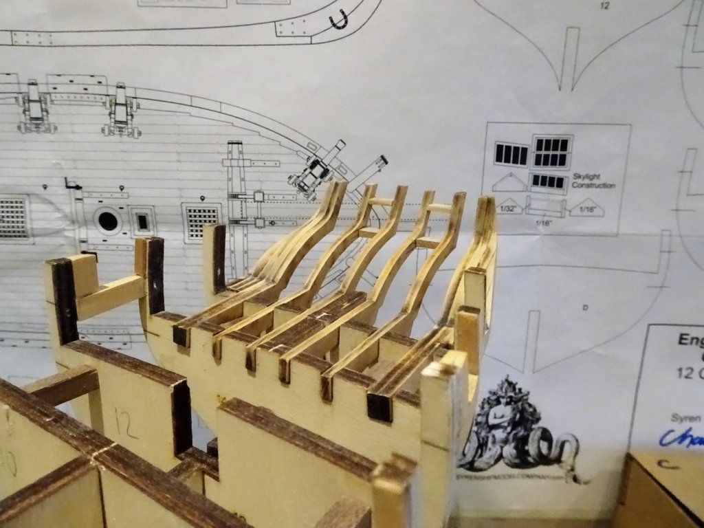
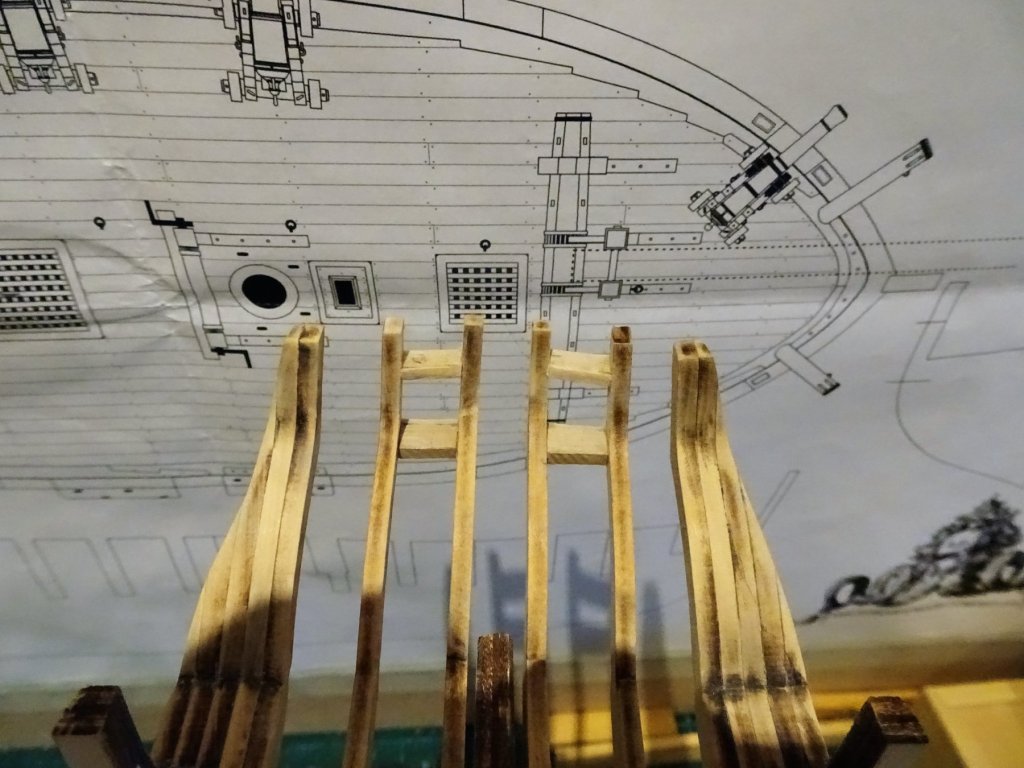
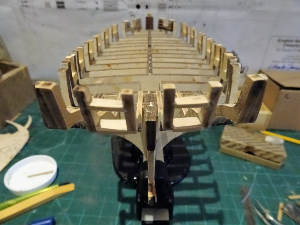
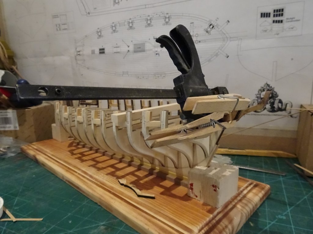
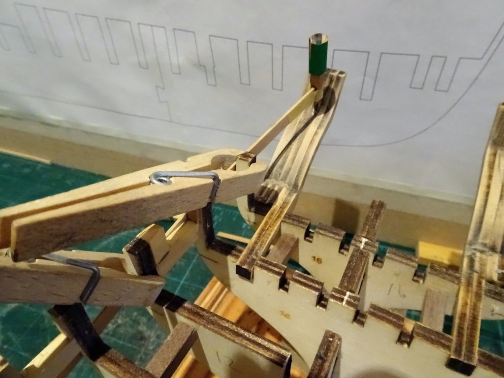
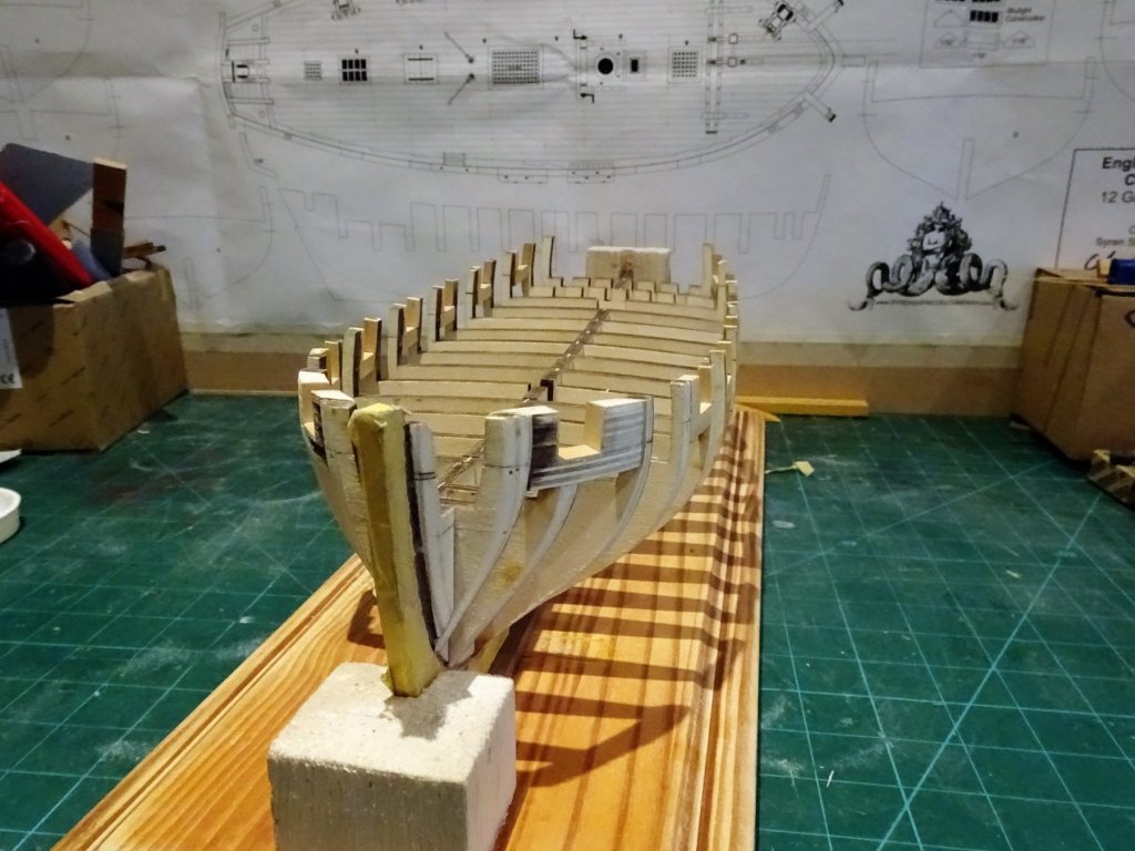
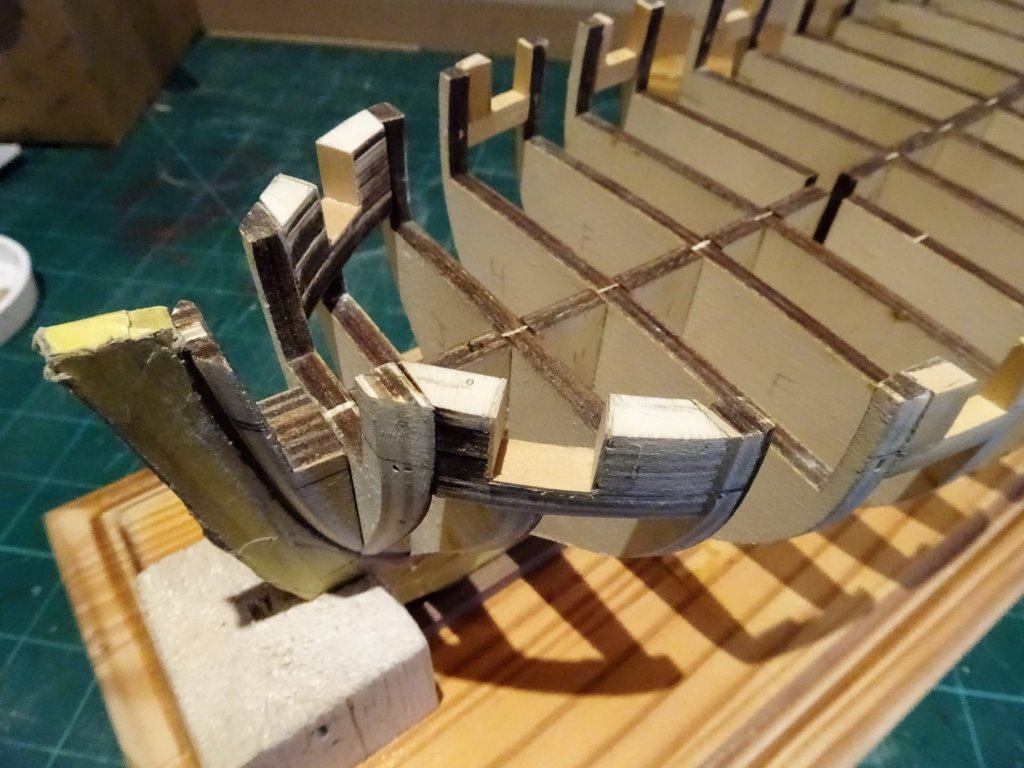
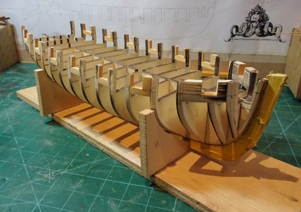
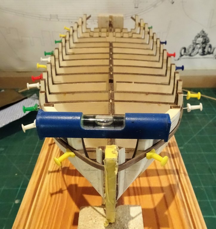
Post 9 Thinking about stern frames Before I started on the stern frames I added short bracing sections of Walnut square stuff between those bulkheads not braced by the Port sills. 4655 The hull is now very stable without any flex in the bulkheads. 4648 getting the levels right for the outer frames 4650 attaching the outer frame sections. These frames are beautifully cut and fit together perfectly. 4654 Marking the approximate fairing line on the outer stern frames. This method of attaching a pencil stub to a wood strip I copied from Rustyj's Cheerful log, thanks Rusty, it worked a treat. 4657 More fairing of the outer frames still required, but at this point I added the four internal frames. 4668 I used a copy of the stern plan to check the set up, not exactly a perfect fit but it did align with frames 'Y' so I took those as the reference points to mark the height of the port frames. 4672 At this point I think I will fit the port sills and lintels which will add a little stability to the quite fine inner frames. B.E. 28/01/2018


- 574 replies
-
- 18
-
-
- cheerful
- Syren Ship Model Company
- (and 1 more)
-
Those are the Boomkins Doug, used to spread the Fore tack. I took my dimensions from Steel and making them from 3mm dia dowel tapered down to 2mm. with a shoulder on the outer end to secure the Fore Tack shoulder Block. Outside of the False rail there is a downward curve in the spar, this was induced by firstly soaking and then curving over a suitable former. No need to be in a rush to fit the Boomkins, they just fit into holes in the face of the Foc'sle. The angle and position of the Boomkins depends to some extent by whether you fit seats of ease to the heads, and whether you fit a false rail which is notched to take the passage of the Boomkin. B.E.
-
Great job on the Long Boat Doug, and I bet you’re glad all those yards have been rigged out. 😊 B.E.
-
If you're referring to the bow area Martin they look like balsa but they are plywood strips glued together to form the bow port section that are cut out later. They will be planked over, but inside the ports a Boxwood lining has been fitted to match the others. The Port interiors are to be painted and considerably thinned down once the exterior planking is done. Cheers, B.E.
- 574 replies
-
- 3
-
-
- cheerful
- Syren Ship Model Company
- (and 1 more)
-
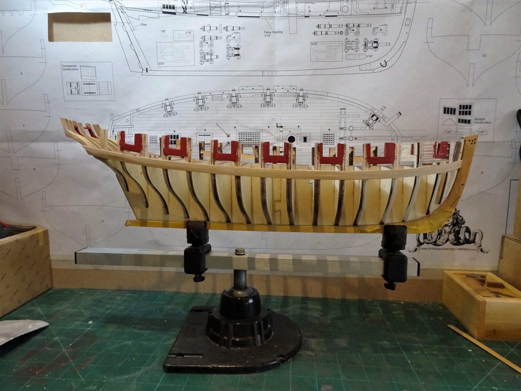
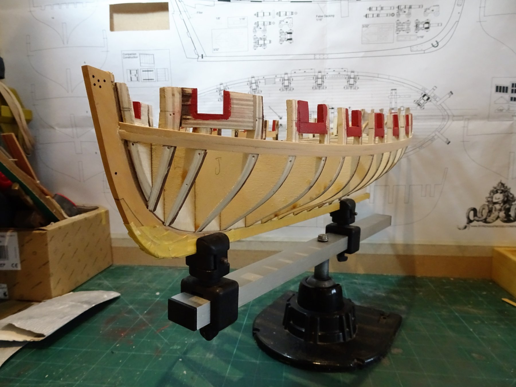
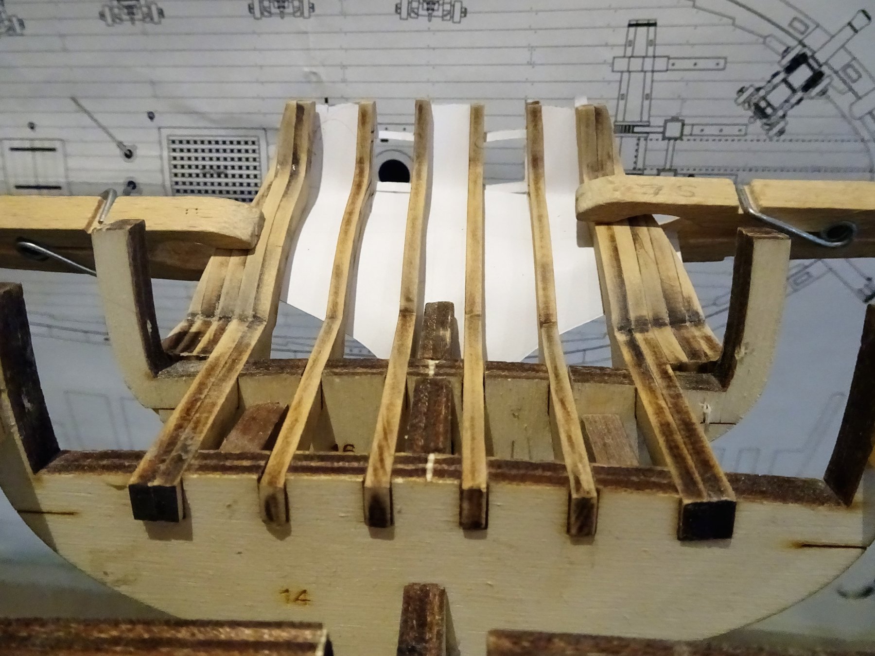
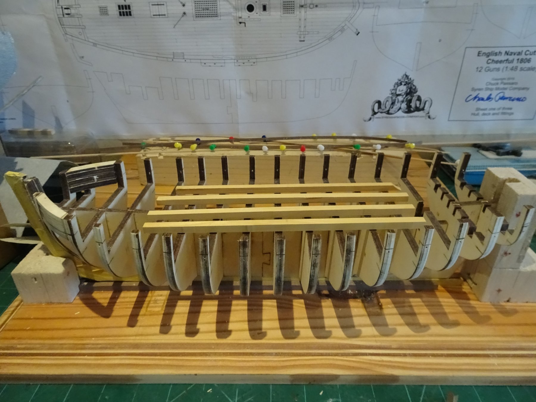
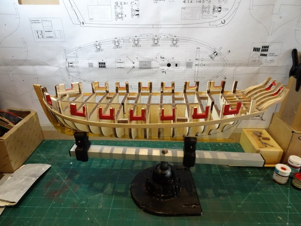
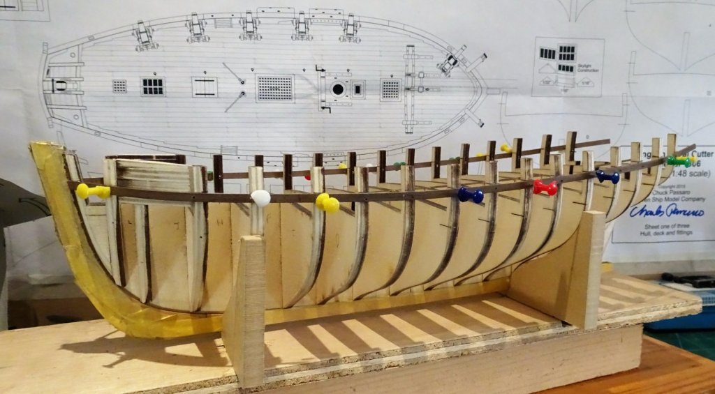
Cheers Guys, Post 8 Port Sills I cut some ¼" square strips from some old Boxwood stuff I had to form the sills. The Proxxon Band saw and Surface planer proved very useful for this job. 4620 More of the stuff was used for the uprights following as far as possible the plan thicknesses, but there were differences in practice. My approach was to fit the thinner uprights on each port and then using a port width template establish the broader upright thickness. When it came to the forward port cut outs I allowed extra width and depth to allow for a Boxwood lining. 4623 I used temporary guide strips for the upright cuts. 4630 Once the bulk was removed, easily done with razor saw diagonal cuts, I cleaned the bottom with a scalpel blade. 4627 The port width template can be seen in this shot. 4641 The linings were then glued into place. 4637 4638 4636 4644 The external port fairing now largely done, now need to consider the stern framing. B.E. 24/01/2018
- 574 replies
-
- 14
-
-
- cheerful
- Syren Ship Model Company
- (and 1 more)
-
Thanks for looking in HH and Tom, and for your appreciative comments. Tom I used 0.1mm dia line for the reef points; not a job I enjoyed, there were over 150 points on the Fore Topsail, with the prospect of repeating it all over again with the Main Topsail. To get them to lie flat against the sail I painted them with diluted pva, otherwise they would be sticking out all over the place and spoil the effect. Regards, B.E.
-
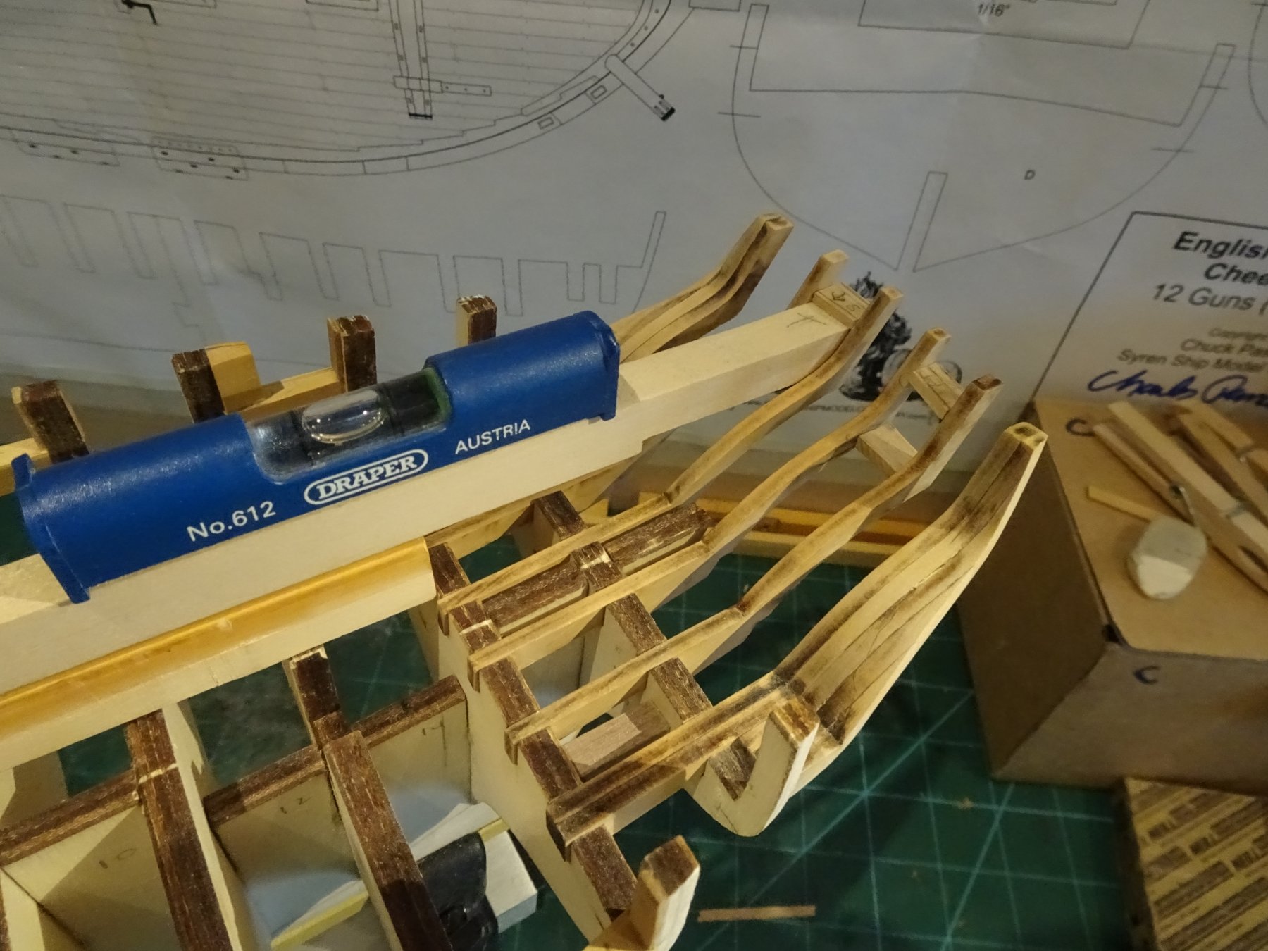
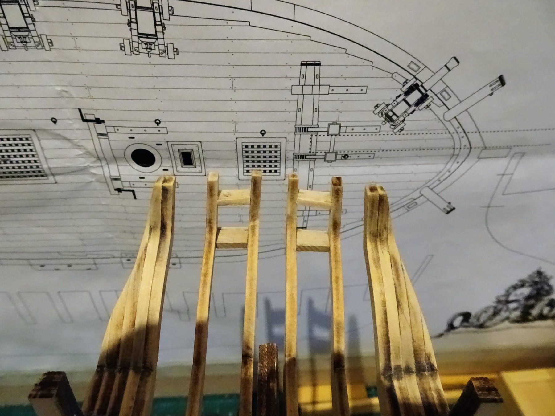
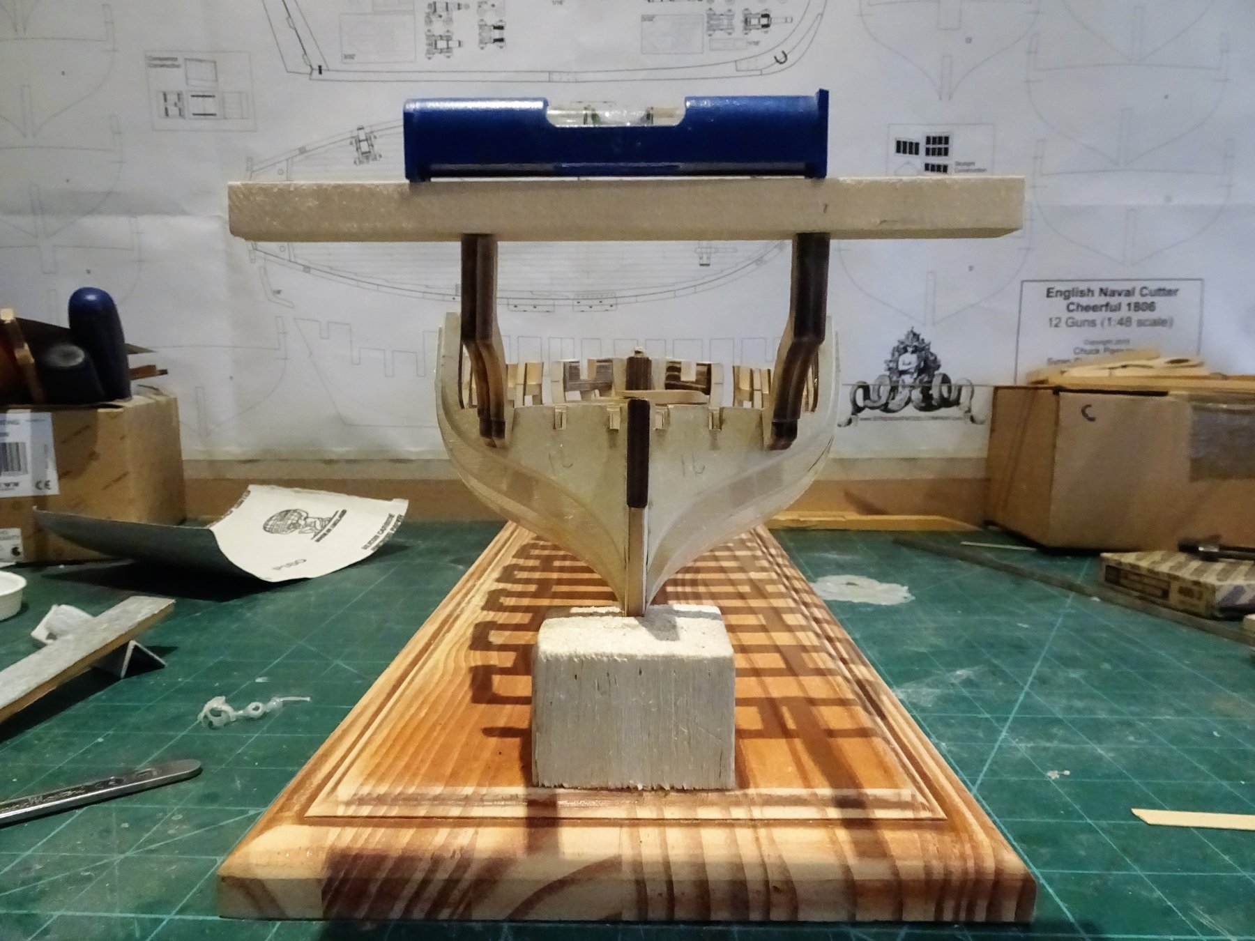
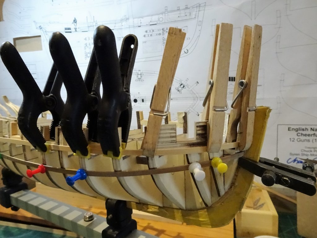
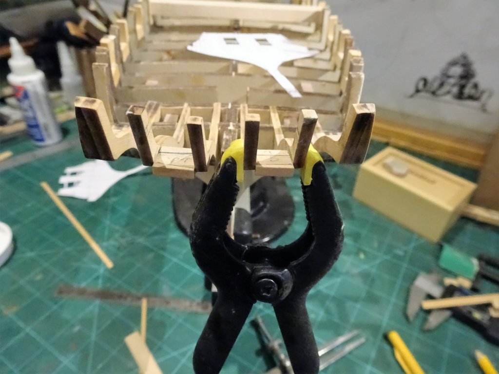
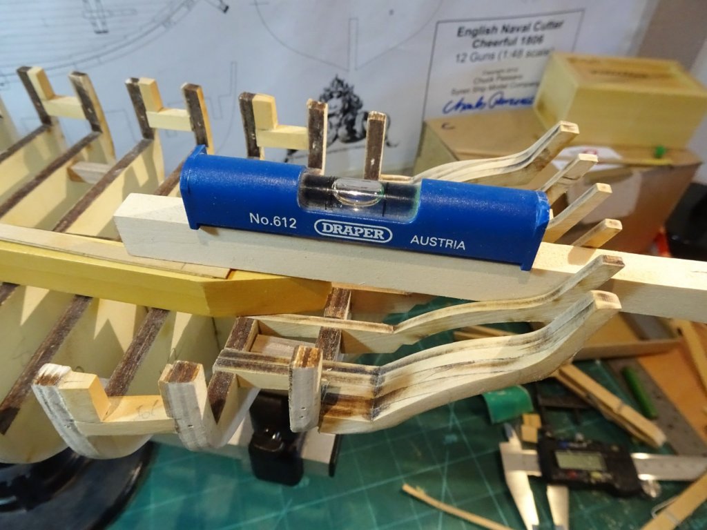
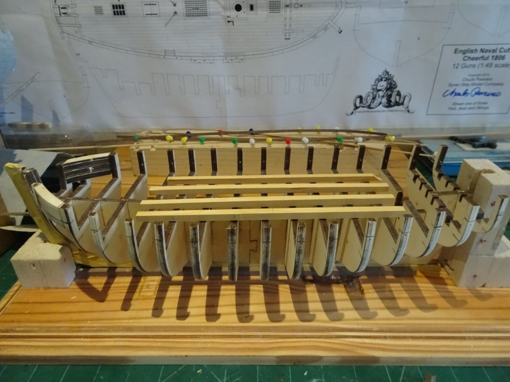
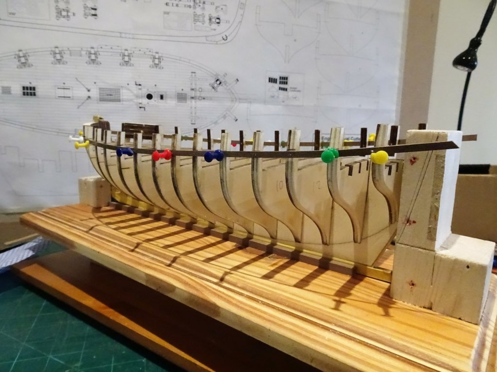
Ah shirt sleeves, the bane of ship modellers, especially when it comes to masting and rigging I shall take great care Kurt when it comes to those stern frames, a little way off yet I think. Post 7 Fairing, fairing, and more fairing. Another day of sand and check, sand and check, and for a bit of light relief, check and sand. 4499 4491 4502 The test strips seem to be sitting fair across the bulkheads, only the central four bulkheads seem to require no adjustment although they will have the char taken off. At this point I think I can fit the batten strip to mark the gun port sills. 4534 Seems to run with a fair curve, at least to my eye. 4540 4544 With the port sills marked, the next stage beckons. B.E. 18/01/2018

- 574 replies
-
- 16
-
-
- cheerful
- Syren Ship Model Company
- (and 1 more)
-
Thank you zappto for looking in on my build 😊 B.E.
-
Thanks Kurt, very useful tips, I would hate to snap a bulkhead extension. I haven’t really thought about the stern frames as yet but I’ll certainly take your advice onboard. Regards, B. E.
- 574 replies
-
- 4
-
-
- cheerful
- Syren Ship Model Company
- (and 1 more)