.JPG.ca33079f5815b861e67b9c2cccd37982.JPG)

Blue Ensign
-
Posts
4,574 -
Joined
-
Last visited
Content Type
Profiles
Forums
Gallery
Events
Everything posted by Blue Ensign
-
 Thanks Martin, both Mrs W and William are quite forgiving of my raiding of their respective possessions to serve in the shipyard. Both Amati and Mantua do a range of period figures for 1:64 scale at around 25mm high. Artesania do a range of 27mm figures one of which I used to represent the ill fated Captain; Cmdr John Hamilton Gore on my Pegasus. In the UK I use either Cornwall Model Boats, or the Model Dockyard, (both in Cornwall) but my 1:24 scale Pinnace figure I purchased from Dean's Marine. Regards, B.E.
- 156 replies
-
- 2
-

-
- pinnace
- model shipways
- (and 1 more)
-
I wish Thomas, no he was a modified bought figure (see my reply to Nils above.) Regards, B.E.
- 156 replies
-
- 2
-
-
- pinnace
- model shipways
- (and 1 more)
-
I don't recognise that as a feature of English gun carriages particularly in the era of your build. Amati are notorious for providing otherwise good kits with generic out of scale fittings, are the gun carriages made of metal? I seem to recall that they supplied their Fly kit with such items, and gun barrels even fitted with dolphins. at one point. The Amati guns provided with my Pegasus kit looked superficially ok, but they were seriously over scale, and not of a correct profile, particularly around the muzzle, and with the bore of a siege gun. By the late 1790's most inboard works were painted yellow; although Red Ochre was still the official colour many Captains requested Yellow, and were in the habit of having their gun carriages re-painted. Not until 1807 did the Navy Board formalise the procedure by notifying Dockyards to accede to Captains requests for a yellow scheme. Vanguard was first commissioned in 1790 and had some re-fits before she fought at The Nile in 1798, by which time she may well have had the yellow scheme, she was the Flagship of Nelson at the battle. Even so I think there is sufficient leeway to give her the Red scheme if you prefer that. B.E.
-
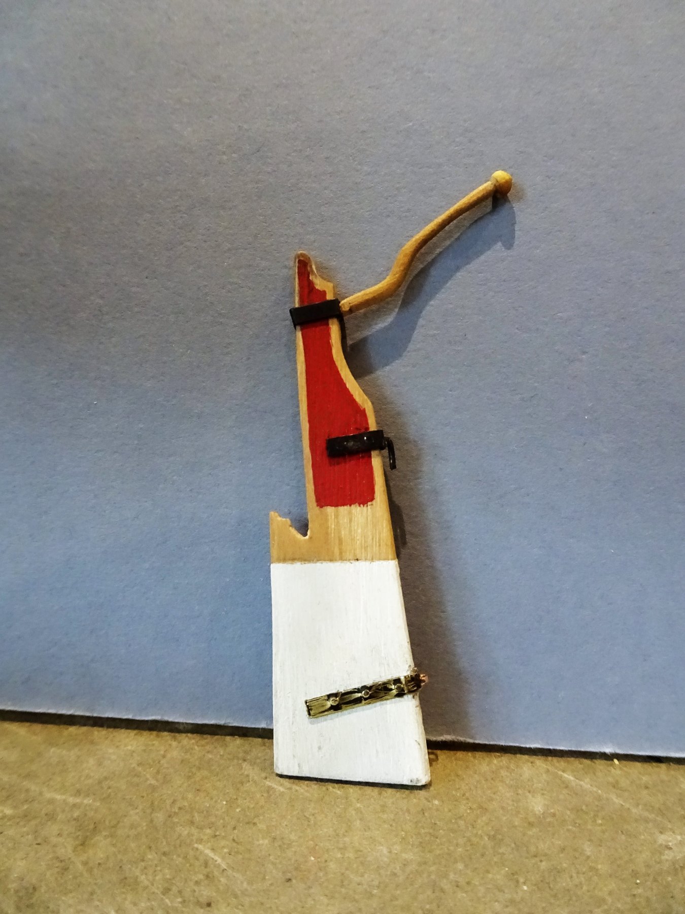
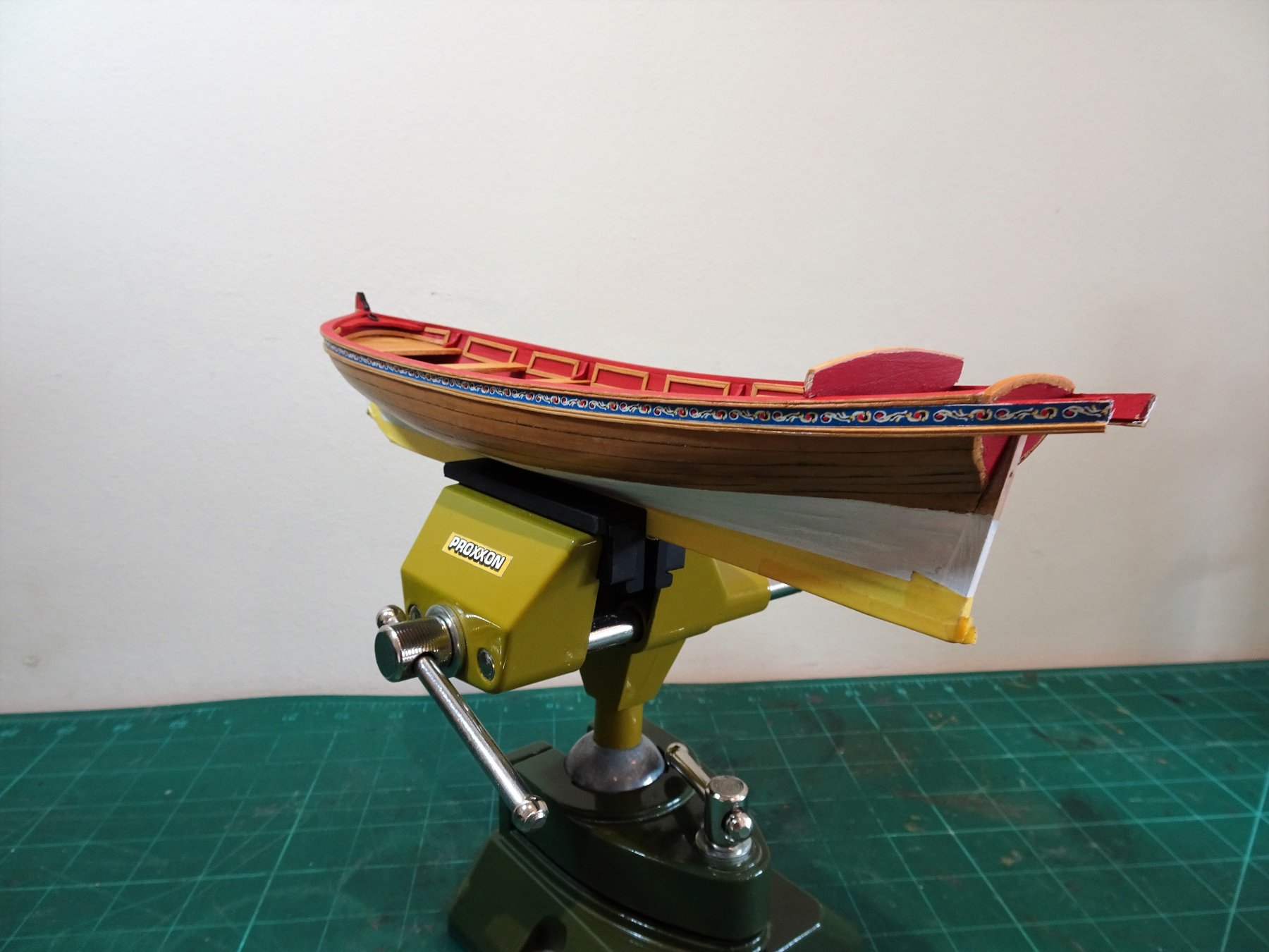
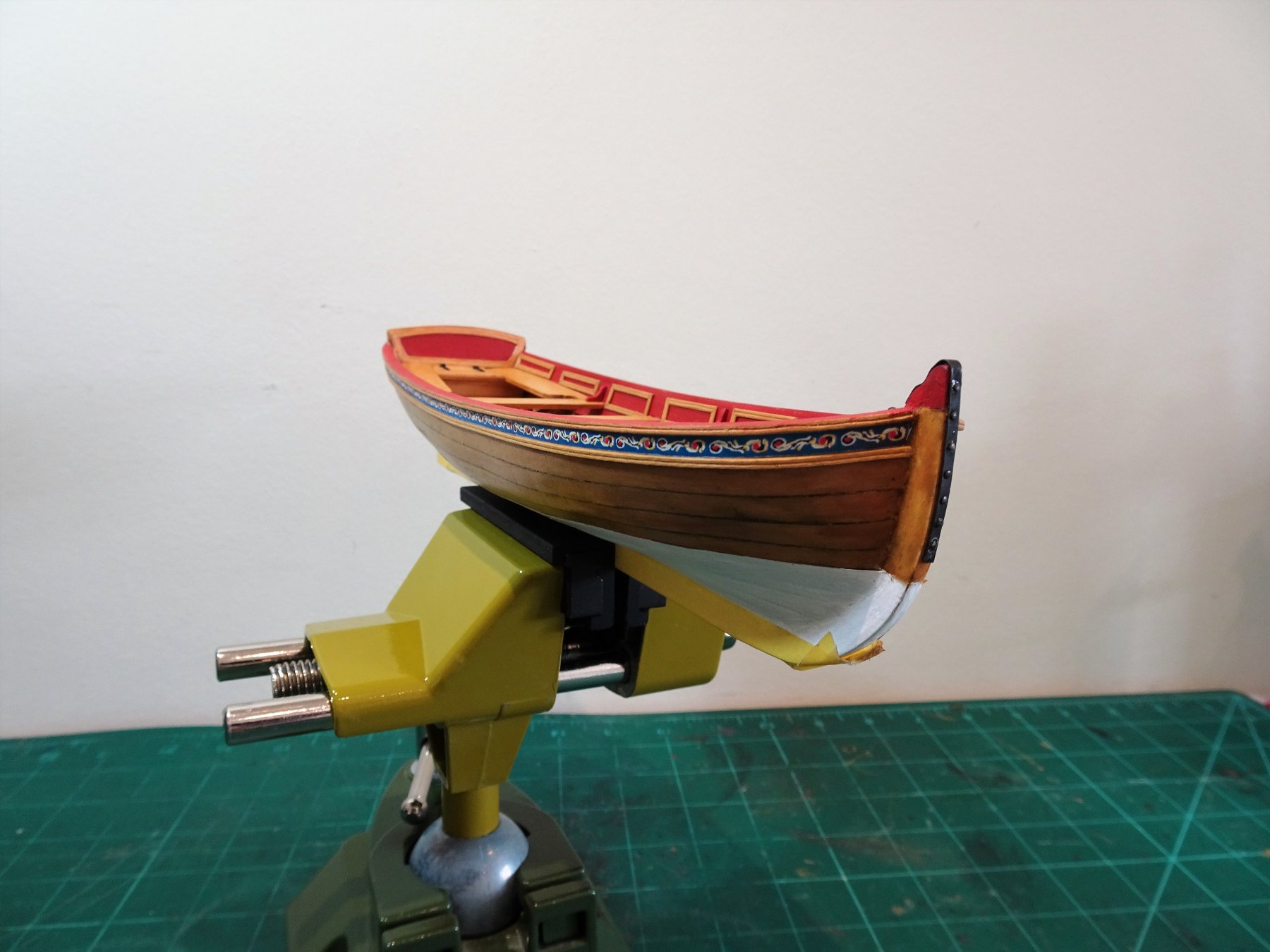
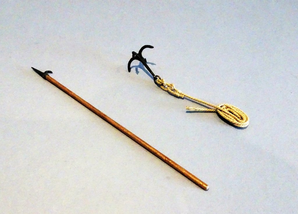
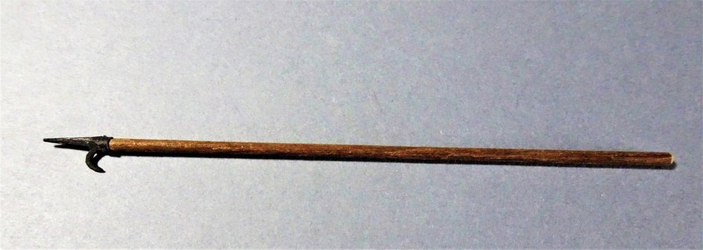
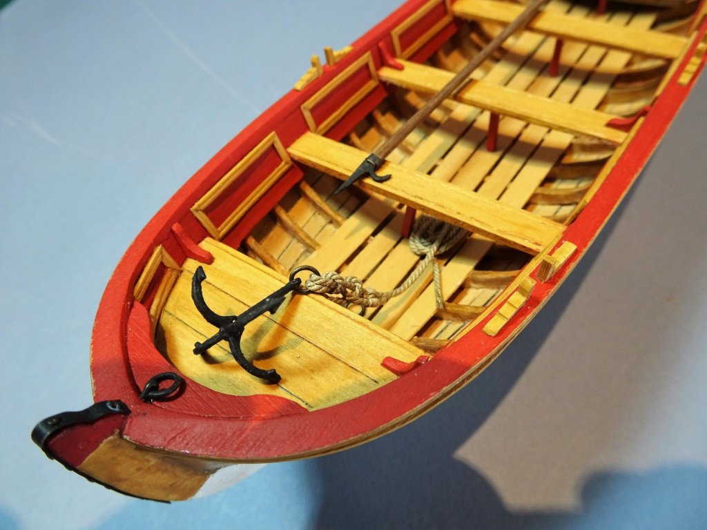
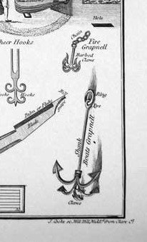
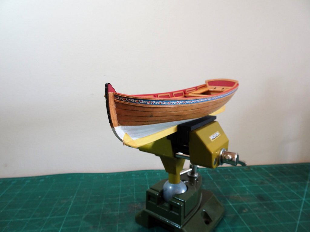
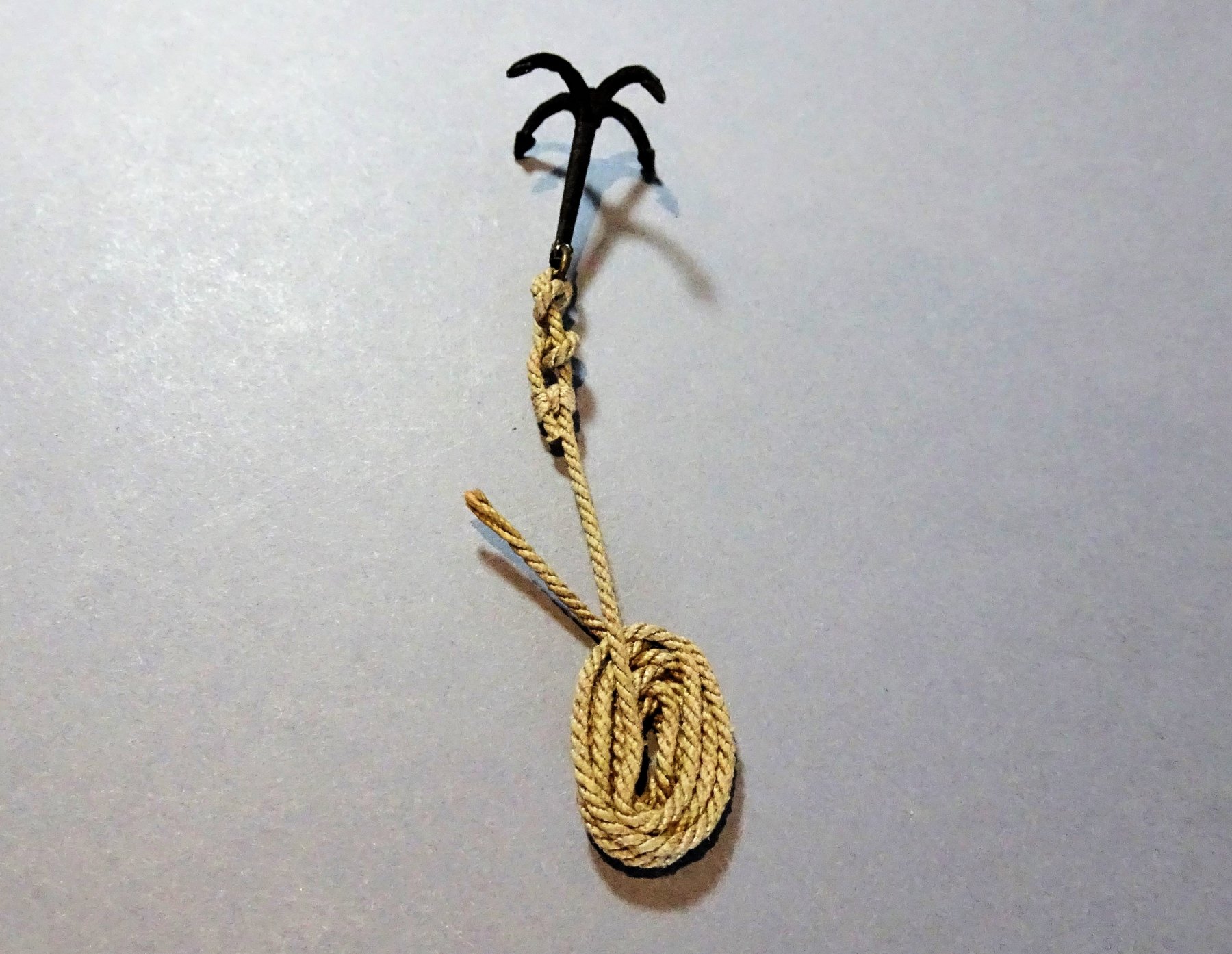
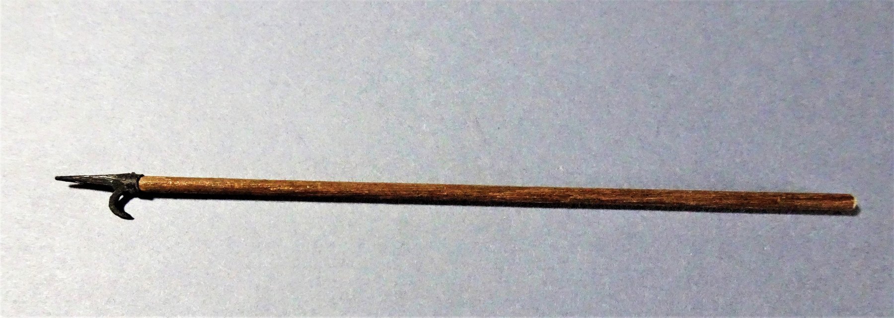
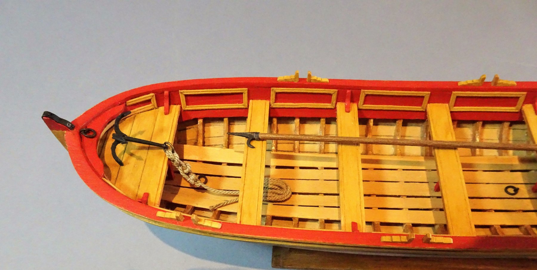
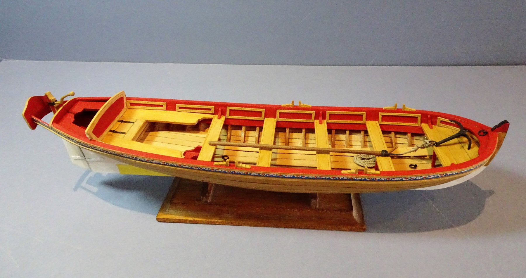
A small diversion to play with the boat equipment. The Grapnel The grapnel as provided by the kit seems to have been rigged without the benefit of a ring, the line secured directly thro' the eye in the shank where the ring should be. A grapnel as illustrated by Steel shows a ring fitted thro' the eye. Steel gives a grapnel rope circ for ships boats as 3" - 3½" which equates to around 1mm diameter line at scale. 0946 This alone would not be possible without a ring, particularly as the classic hitch for small anchors is a Fisherman's Bend where the line passes twice thro' the ring. He also gives 35 fathoms as the length of the grapnel rope. which scales to 2667mm. This is 8.75ft at scale, where would all that fit in the boat! 0967(2) I satisfied myself with a rope length of around 30' - 300mm which I figured would be long enough for what is essentially a harbour boat. Boat Hook This is shown on the plan but the makings are not included with the kit. 0950 Not too difficult an item to reproduce, I use a soft white metal strip (the arm from one of Mrs W's hair clips, cut and shaped with files, and inserted into a length of thin Walnut dowel. 0948 0964 0956 The Thole pins and chocks are also shown on these shots. Nothing much to say about the tholes except they are fiddly little things to make, parts very small, fingers too big. I changed the style slightly from the plans, and left them unpainted as a contrast to the predominantly red scheme. 0961 Just the Splashguards left to do now. B.E.


.thumb.JPG.38d3a8328c45b266293644fe6f30c99c.JPG)
- 156 replies
-
- 20
-
-
- pinnace
- model shipways
- (and 1 more)
-
Thank you Sailor and Nils. @ Nils - George is a Dean's Marine 1.24 scale figure, but he underwent some serious surgery. originally he was a Vietnam War period American soldier in Jungle gear. His arms were broken in two places, his uniform and jungle hat cut away and he was given some clothes from the slop chest. I was pleased that at a given 1:24 scale he fitted the boat spot on. B.E.
- 156 replies
-
- 3
-
-
- pinnace
- model shipways
- (and 1 more)
-
A beautiful model Chuck, and a fine unique kit, I too will be looking forward to ordering one. B.E.
- 269 replies
-
- 7
-
-
- Queen Anne Barge
- Syren Ship Model Company
- (and 1 more)
-
Thanks Jason, when you start to look the subject of oars you find there is a huge amount of info out there, including many forums on every aspect from making to using, designing and purpose. From what I've read I think you are right that the thicker part of the oar whether it be round or square is primarily to provide balance and improve handling. One reference I looked at said that the square part begins just inside of the pivot point, so perhaps the Pinnace set up is not that far out. B.E.
- 156 replies
-
- 2
-
-
- pinnace
- model shipways
- (and 1 more)
-
This has been a fabulous project to follow Nils, many congratulations on completion on yet another wonderful model. Love your growing museum collection B.E.
- 2,625 replies
-
- 4
-
-
- kaiser wilhelm der grosse
- passenger steamer
- (and 1 more)
-
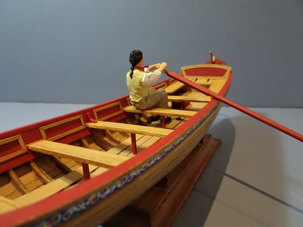
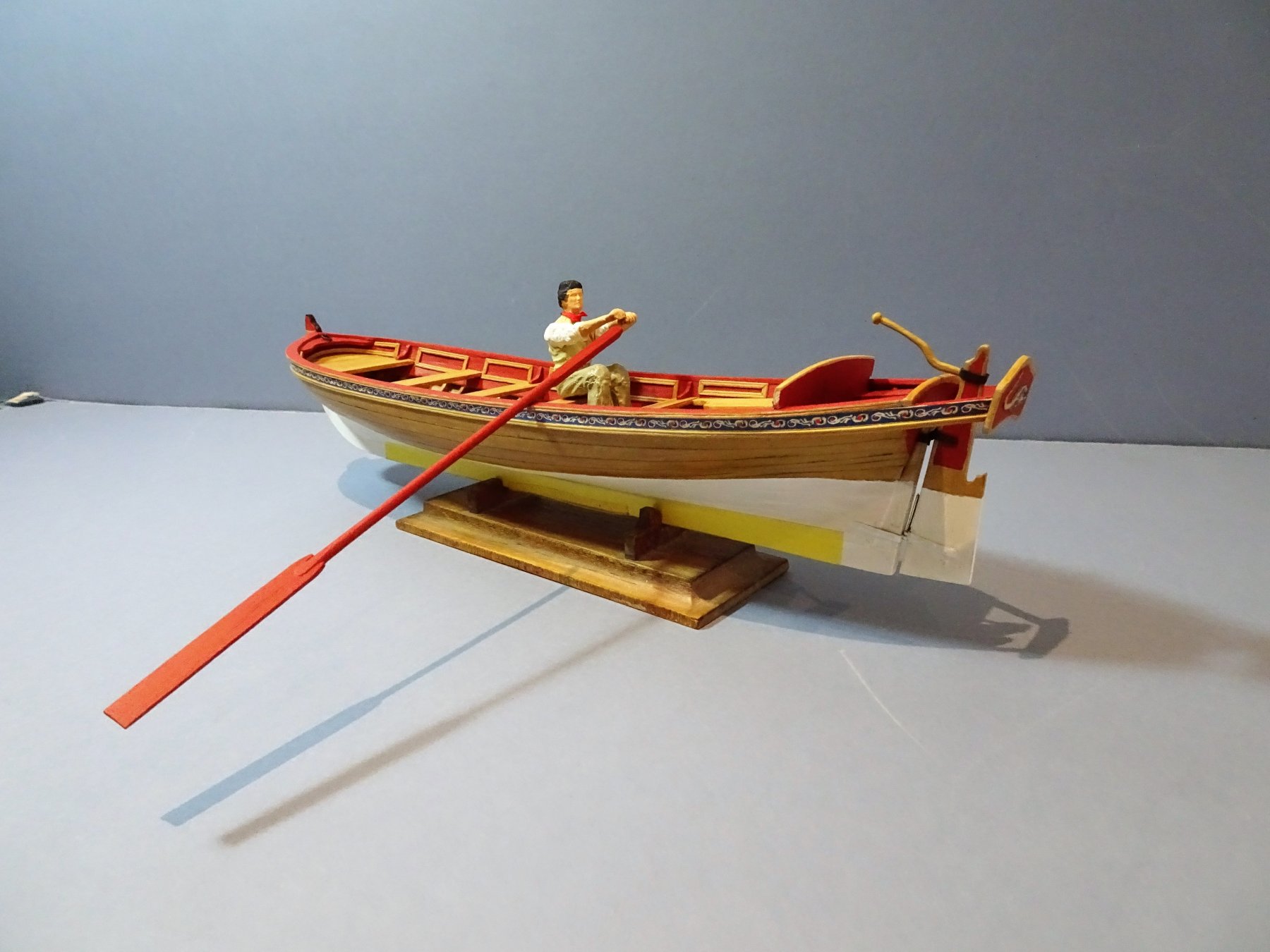
Thank you Steve, Mark and Martin. @ Mark and Martin - With a single banked arrangement the rower should be close to the opposite side to the tholes, to gain maximum leverage. Here's a modern version of single banked rowing and you can see the rowers are close to the sides. These modern oars don't seem to have the old style looms but rather a slightly thickened and protected area where the oar passes thro' the oarlocks, although in this case not all the oars are set the same. Not sure Martin that the extension outboard of the oar should change with the forward/backward movement of the rower, but I base this purely on my very limited experience of having an occasional scull up the river. Cheers Guys, B.E.
.thumb.jpg.9982c2a3cf001f6c35eba8eba2c486a8.jpg)
- 156 replies
-
- 8
-
-
- pinnace
- model shipways
- (and 1 more)
-
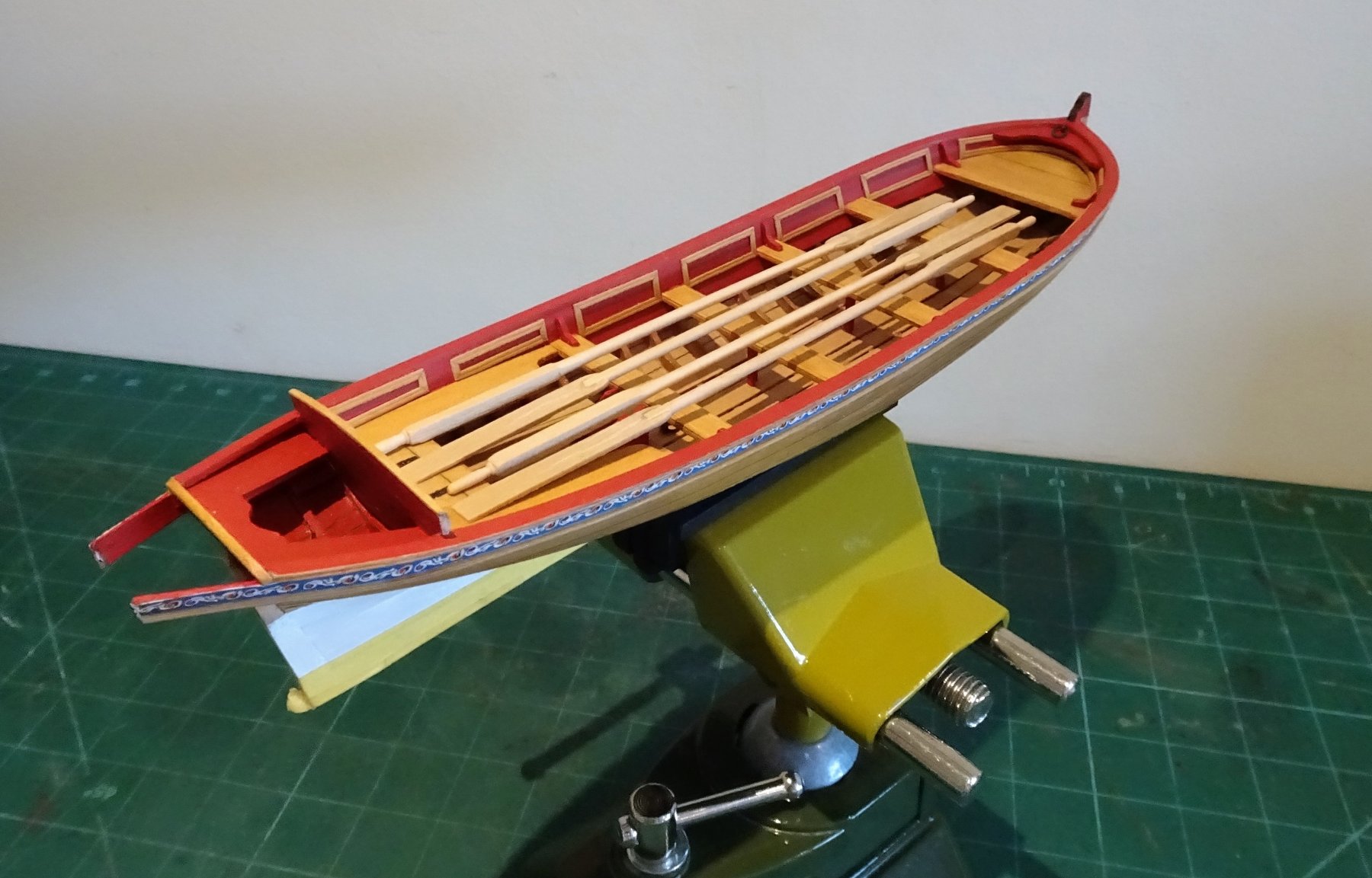
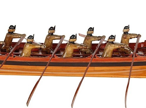
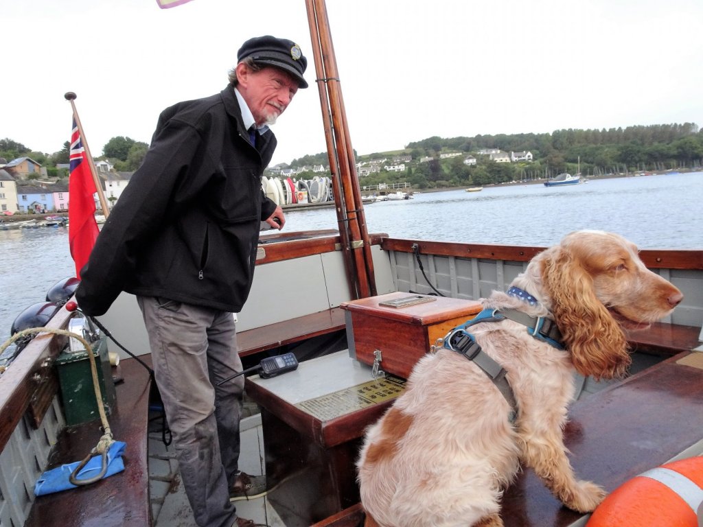
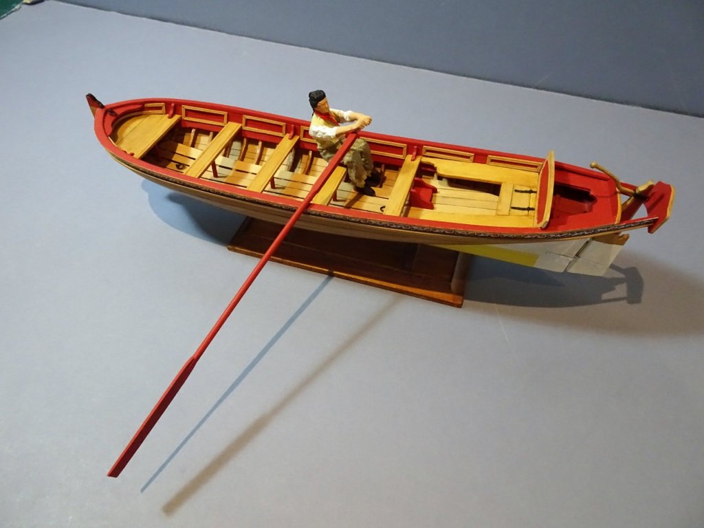
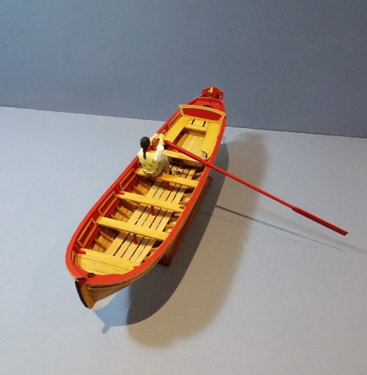
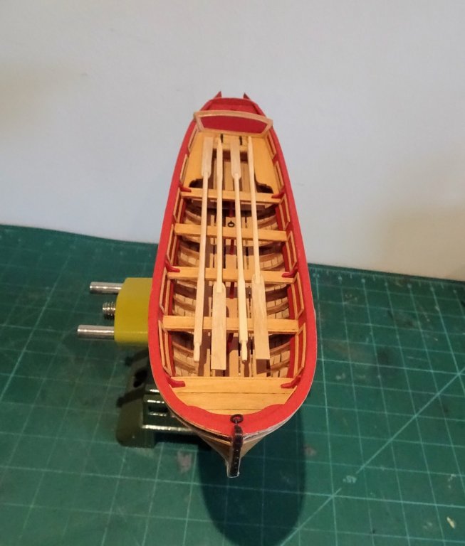
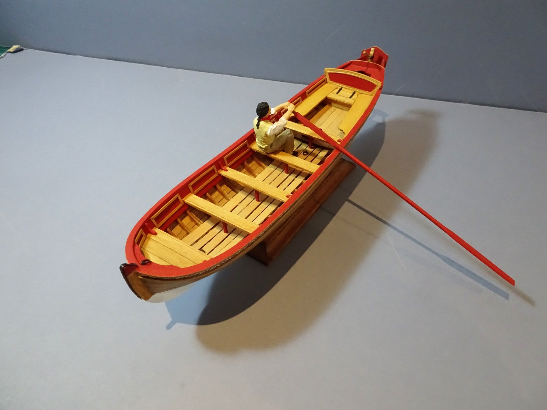
Back from the fair county of Devonshire, William had a fine time on the Dart. 0720 Here performing his lookout duties as we cross from Dittisham to Greenway. Back to the build and in relation to small boats I like to have a scale figure to check the relevant proportions of any model I build, and here is George one of the oarsmen. 0922 Here you can see that with George in position the oar loom doesn't quite reach where the thole pins will fit. Is this correct, should the loom fit between the thole pin centres? the plans would suggest that this width would allow the thicker section of the oar to pass thro'. In this contemporary model the looms appear to just catch the thole pins. I was interested in the oar proportions and the relationship to the tholes. There's a lot more to this oar and thole business than you might first think. The Length of the oars has a direct relationship to the width of the boat, and whether it is single or double banked; the tholes to the distance from the aft edge of the thwart. On our model the centre of the chocks scales to 13" from the relevant thwart edge which puts it about mid centre between thwarts. Looking at boat plans this seems to generally be the case. Our boat is scaled to a width of 5'11" The oars on our boat are 186mm length overall with a Loom length of 37mm. This gives a length of 14.6' and a loom length of 2.9'. 0929 This is the link to the online reference tables by Steel. https://www.thebigrow.com/?p=659 I must admit I couldn't make any sensible correlation between the Steel figures and our model. Looking at his tables relating to Barge,Wherry,or Skiff the oar lengths seemed much longer for an equivalent breadth to our Pinnace. This of course is all academic as the oars as modelled look proportional to my eye, and resting along the thwarts there is no direct reference to the thole positions. Need to fix the Thole pins and chocks now. B.E.

- 156 replies
-
- 17
-
-
- pinnace
- model shipways
- (and 1 more)
-
Those look beautiful Martin, I would be reluctant to paint such fine work, whereas my own utilitarian version certainly required blackening. As far as height is concerned, if your Captain is Captain Silver of the Amati Line, then he stands 27mm high including his Bicorn hat, so just about his head would appear over the rail, Having said that he is quite a slight figure at around 5' 6", but then so was Nelson. I used an Artesania figure to Captain my Pegasus, not much taller but a more substantial figure wearing a long frock coat and Tri-corn Hat more uniform appropriate for the period I thought. Cheers, B.E.
- 467 replies
-
- 2
-
-
- fly
- victory models
- (and 1 more)
-
Looking good Snow, and you seem to be enjoying your first build, which is the prime objective of getting into this fascinating activity. If your ships boat is 70mm in length it scales to a small boat of around 14 feet, so as finger in the wind job I would say oars of between 7' to 8' in length which scales to 40mm. You could try the formula based on width between the oarlocks/tholes; Firstly measure the width of your boat in mm between the oarlocks and scale up to full size eg: scale width 20mm; multiply by 60 then divide by 25.4 = full size in inches. (47.24") The formula is then: Divide by 2, then add 2 inches. take this number, multiply by 25, divide by 7, and that's your approximate answer in inches. multiply this by 25.4 and divide by 60 to give the scale length in mm. for your model. Hope this helps rather than confuses B.E.
-
What type of boat, scale, and period is it? B.E.
-
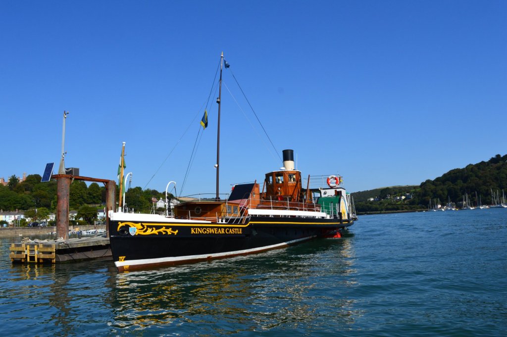
Very much a working boat Martin, the last remaining coal-fired paddle steamer in operation in the UK today. She was built in 1924 at Dartmouth but her engines date back to 1904. Perhaps of interest to yourself she was loaned to the US Navy during WW11 as a harbour tender. She was restored at Chatham over 15 years and offered River trips on the Medway. In 2013 she returned to the Dart where she continues to provide river trips. Might have a trip on her later this week. B.E.
- 156 replies
-
- 2
-
-
- pinnace
- model shipways
- (and 1 more)
-
Thank you Martin, Steve, and Michael. The dolphin image I found online; reduced it in size, printed it off, coloured it, cut it out with a scalpel, and fixed it with pva. Here you are Martin a holding pic of one of the Dart's iconic residents. Cheers, B.E.
- 156 replies
-
- 1
-
-
- pinnace
- model shipways
- (and 1 more)
-
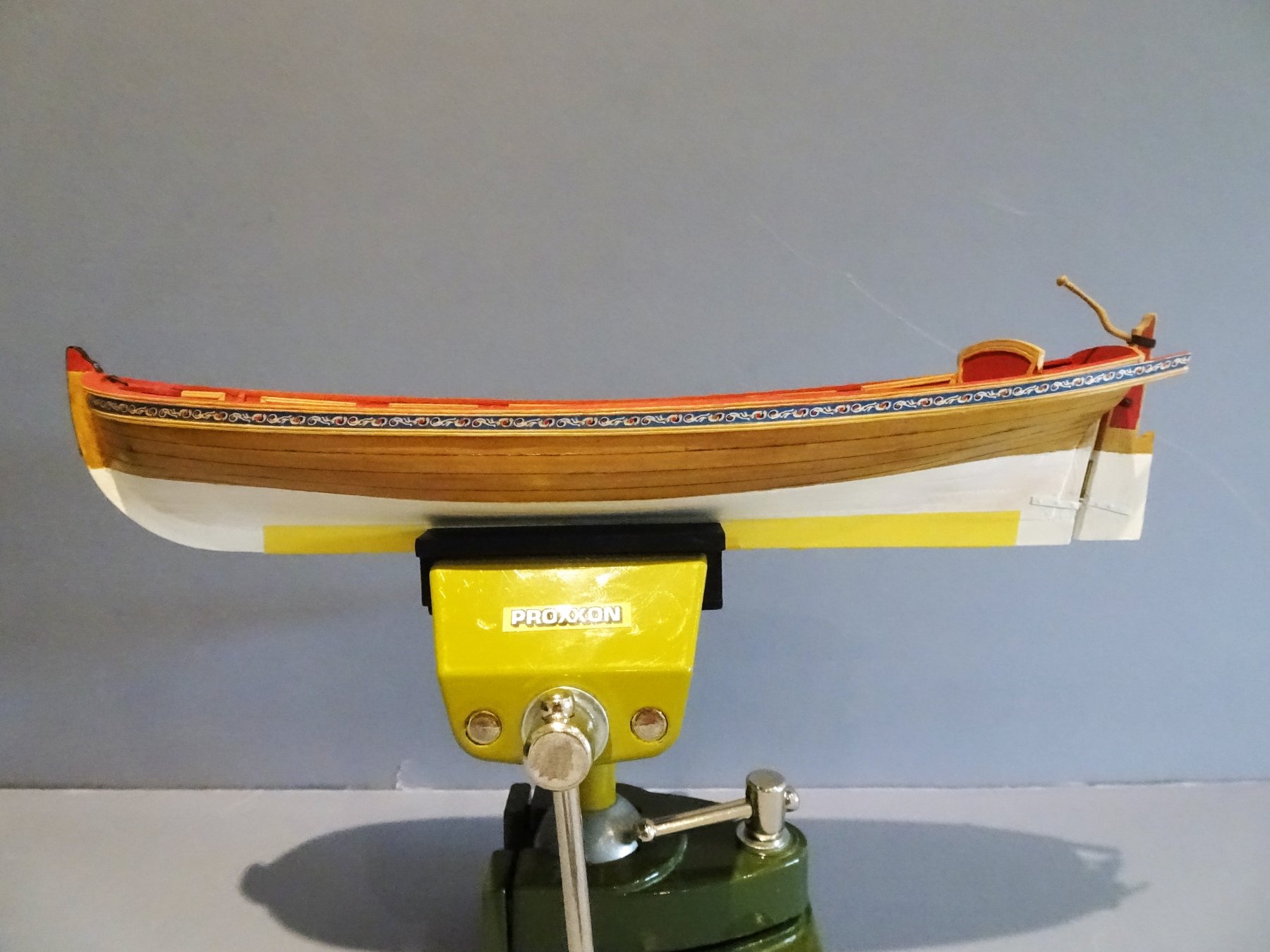
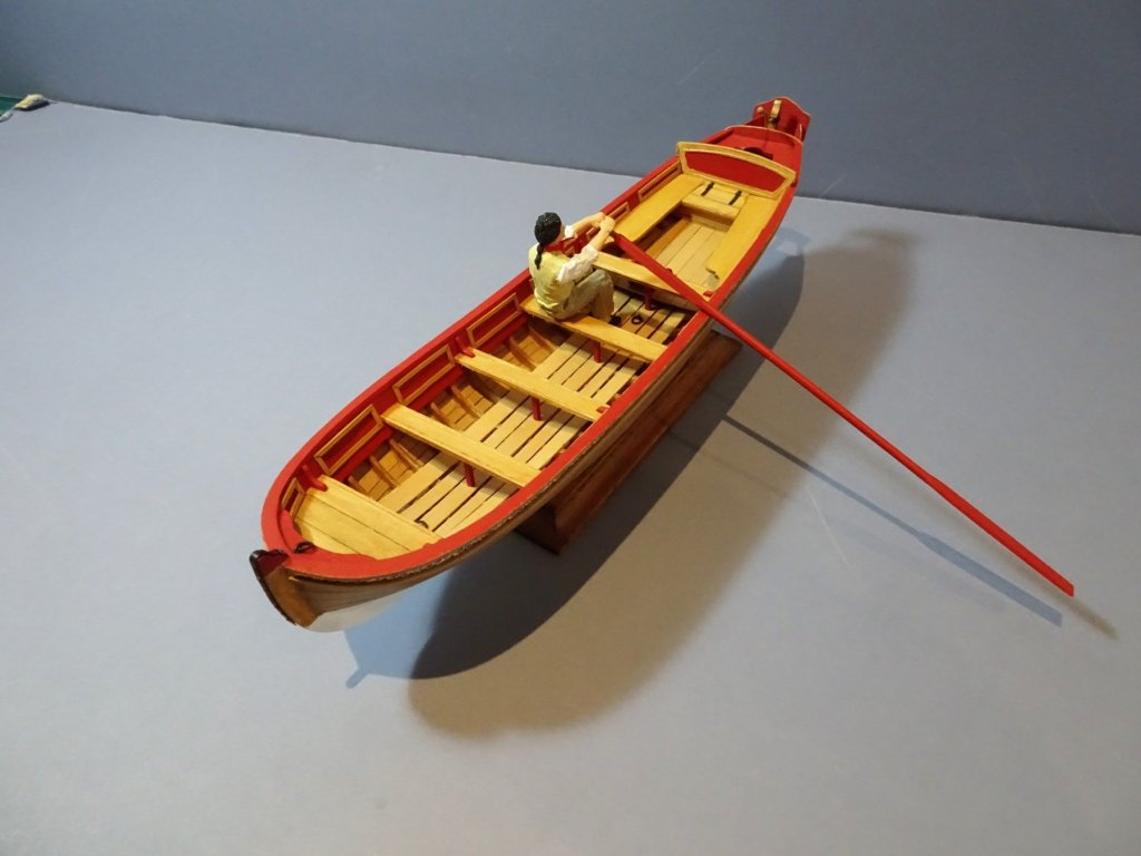
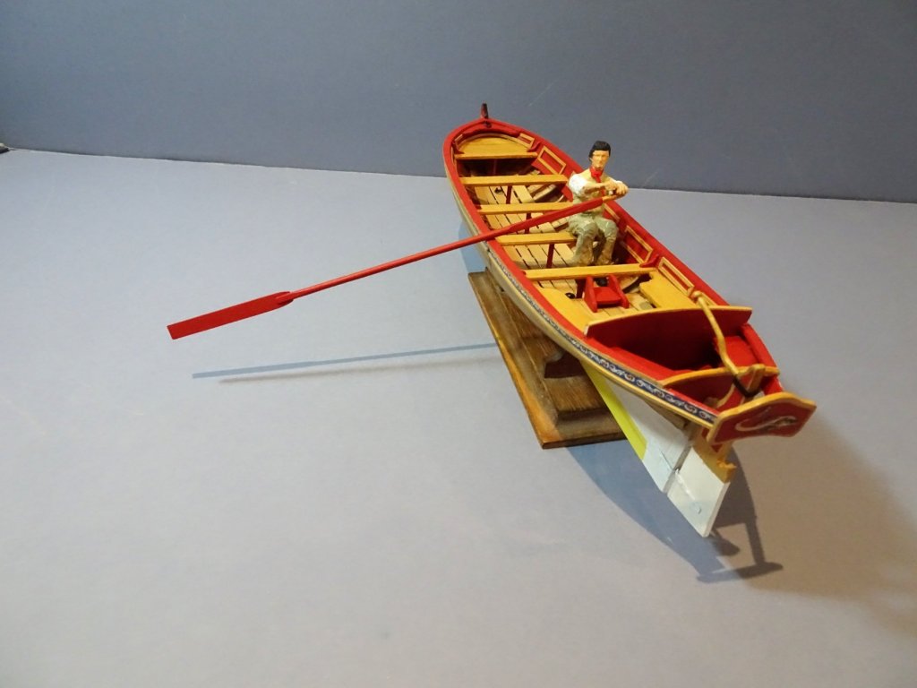
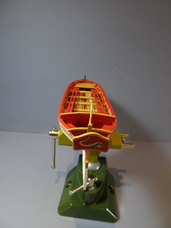
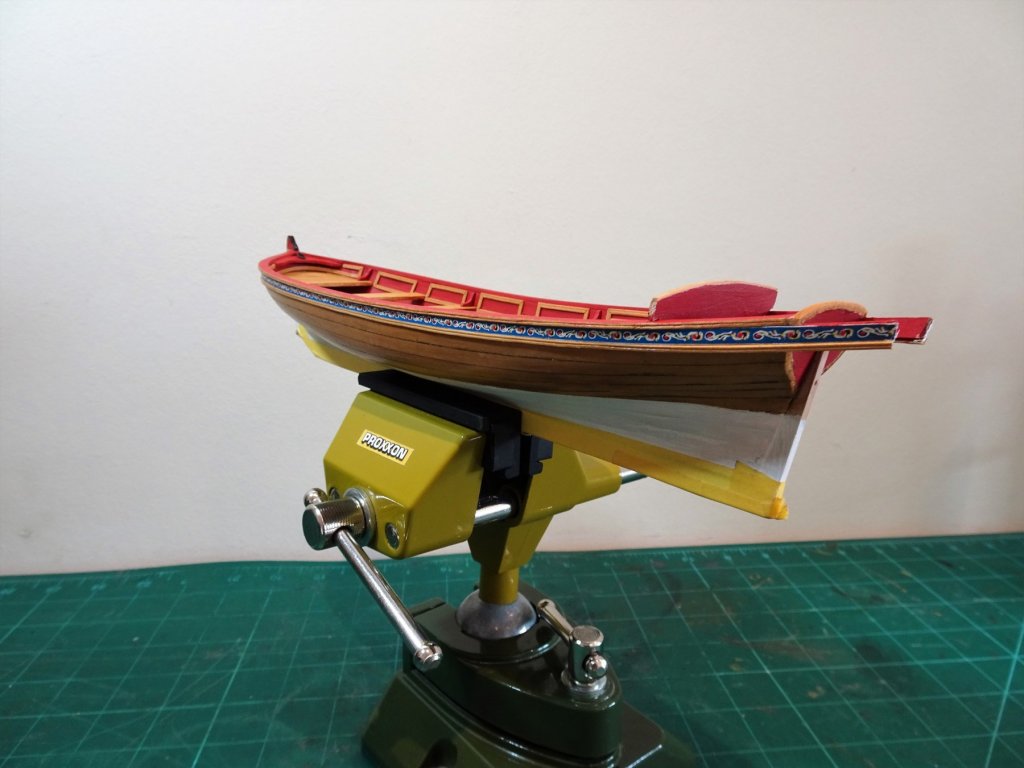
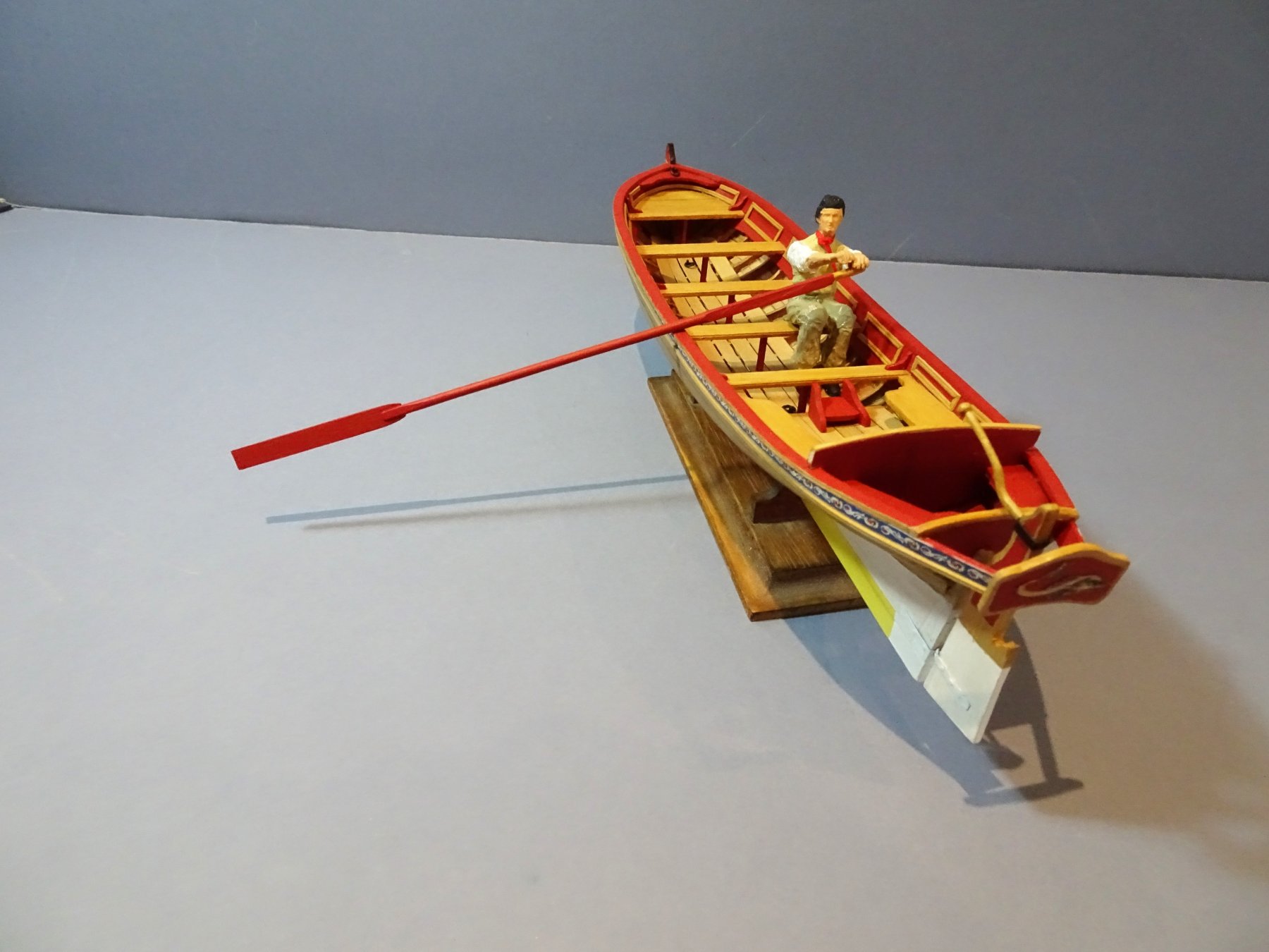
The Decorative Transom As I commented earlier in the log I decided not to use the kit provided metal piece partly because I wanted a Boxwood version and partly because I didn't particularly like the indistinct raised design which appears to be the Royal cipher. Our boat is a small Pinnace not a Royal Barge, so I doubt the Royal Monogram would feature on such a vessel. 0394(2) On my version I have however included a Dolphin design, something a moderately comfortable Captain with a few spare Guineas in his purse may afford. 0402 0407 0417 I also made the decision to paint the oars red overall, but leaving the handles natural. 0426 0436 Getting close to completion now just the Splashboards and Tholes to add, but they will have to wait as I'm off to the South West for a week messing about on the River Dart. B.E.
.thumb.JPG.61e02fd1b33191614e244fe47f332e60.JPG)


- 156 replies
-
- 17
-
-
- pinnace
- model shipways
- (and 1 more)
-
if you've got some flexibility in the arm Jason, then I think you're good to go . look forward to seeing the final outcome. B.E.
-
Superb work on the coppering Jason. I had a similar issue with the Quarter figures when I decided to retro modify the stern on my Pegasus, and replace the flat etched figures with angled relief figures. I had to chop quite deeply into the transom for my modification and I spent some time visualising how I would approach the task before I took knife to the stern. I wonder if the raised arm of the figure would present a problem. If the figure is simply placed at an angle the arm would be away from the face of the transom unless the figure is set into the edge and the angle of the arm can be modified somewhat. I think I would make a stern mock up using some stuff of the same thickness and see how it worked out. Cheers, B.E.
-
You're doing a great job on this technical and testing aspect of ship modelling Michael; sometimes confusing, and sometimes frustrating, you're masting and rigging will compliment your beautiful hull work perfectly. Regards, B.E.
-
Beautiful work Bob, and I love the configuration of the deck planking with the combination of Box and Holly. I'm not so sure about the grating strips which to my eye look somewhat at odds to the rest of the timber in terms of colour and fineness of finish. B.E.
- 682 replies
-
- 3
-
-
- halifax
- lumberyard
- (and 1 more)
-
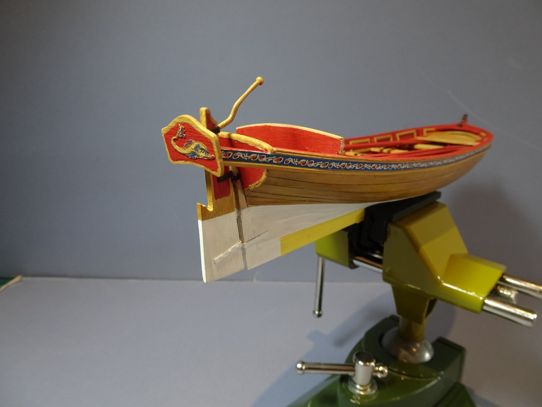
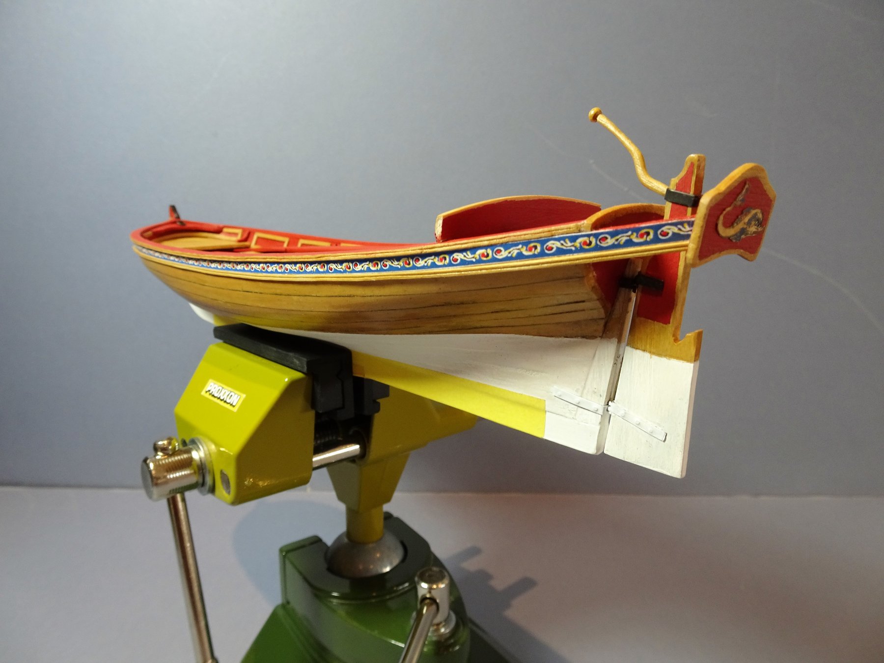
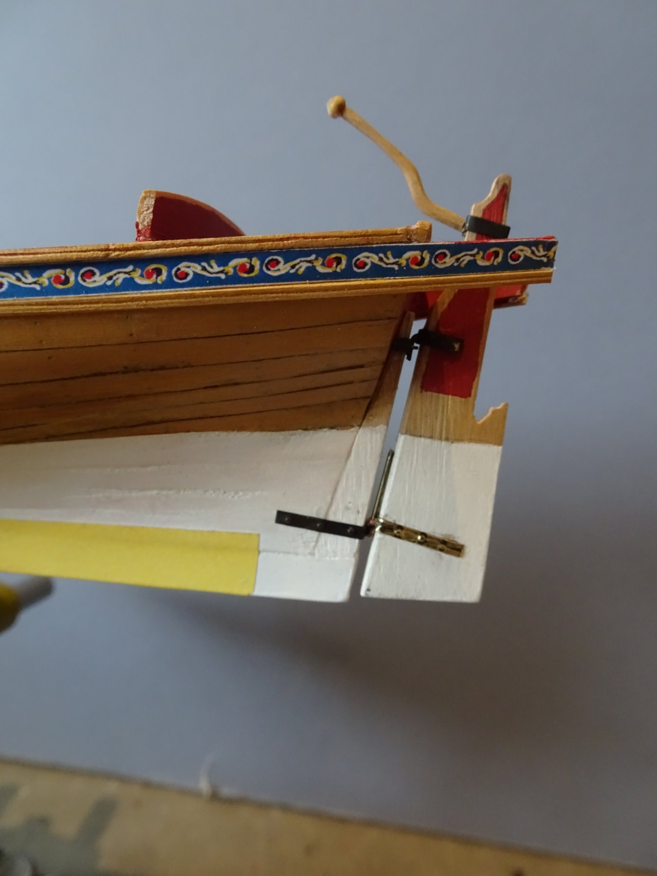
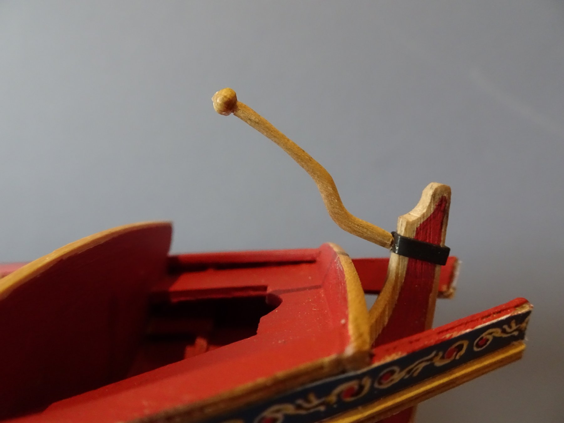
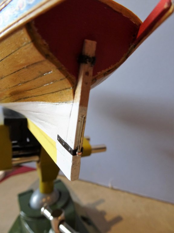
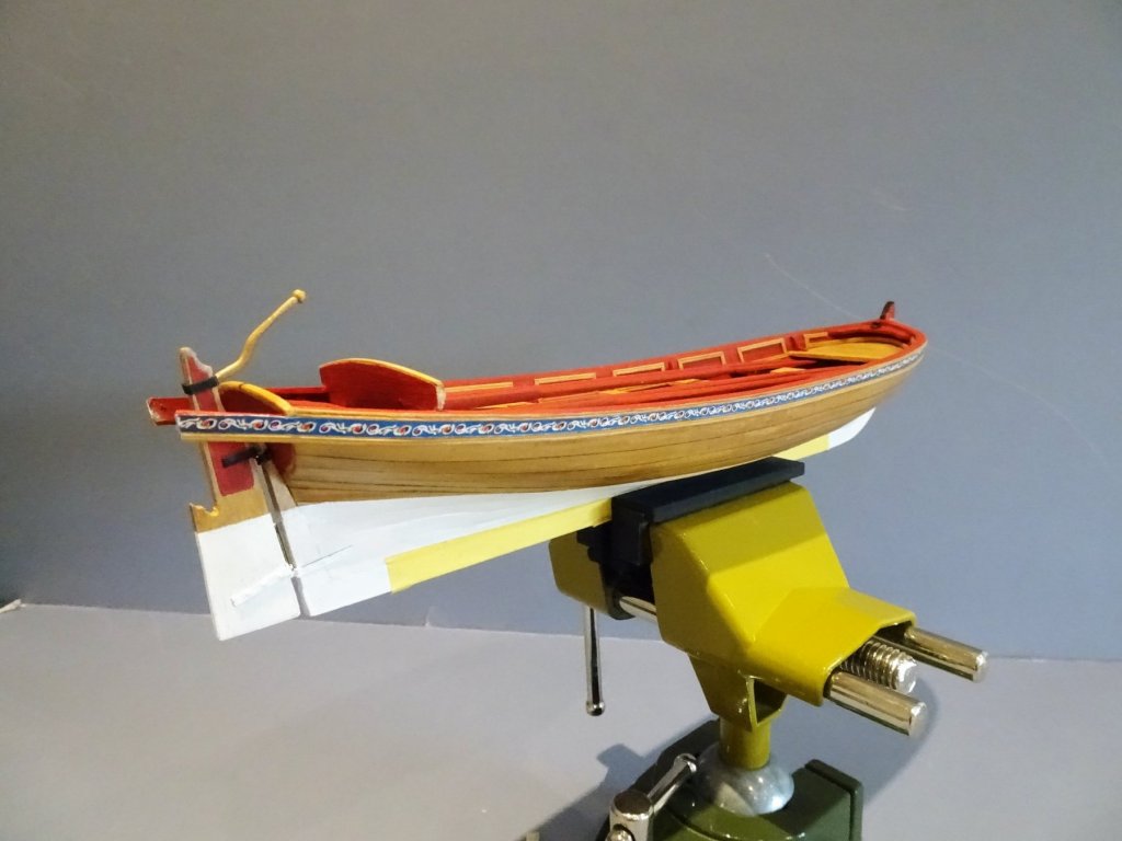
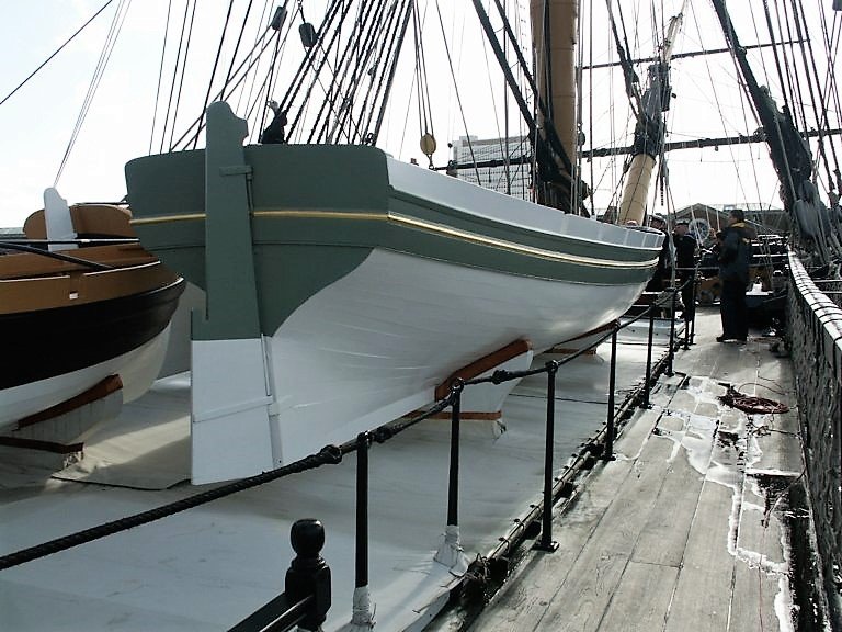
Thank you Martin, Mike , and Thomas. @ Martin - I don't think I did anything special with the Breast railings, although I did drill sheave holes in the lower parts. The lathe extension really comes into its own for the larger scale models, and it came in very useful for the Pegasus masts and yards.. @ Mike - I love all the Proxxon machines, they're perfect for my level and range of ship modelling. @Thomas - I doubt you need any tips from me having looked at your Syren build. I've also got the Long boat kit, along with 'Cheerful' but I'm very much drawn to Chuck's latest offering the 'Royal Barge' The Rudder Before I attend to the Splashboards and thole pins I think it better to make and attach the Rudder. I used the kit provided piece as a template to make one out of Boxwood. 0377 The tiller is cut from Boxwood sheet and shaped with files. For the ball on the end a Boxwood parrel bead was brought into service. For the Gudgeons, pintles, straps, and iron band around the tiller head I used brass strip chemically blackened. 0371 Speaking of gudgeons and pintles I have deviated from the kit. Lavery (Arming and Fitting) indicates a different approach to hanging the rudder to that suggested by the MS kit. 0379 The rudder was hung on the sternpost by only two gudgeons and pintles. Unlike the rudder on a ship it was likely to be hung and unhung every time the boat was used and it needed to be easily removeable. The lower pintle was fitted to the sternpost rather than the rudder. It was very long and extended almost up to the waterline. The upper one was shorter and fitted to the rudder. This makes quite a lot of sense if you imagine trying to ship a rudder in a pitching boat with the gudgeon below the waterline. Having a long pintle at the lower end would make for easier and quicker location of the rudder. Looking through some of the drawings in the AotS Books – The Frigate Diana, Endeavour, show the ships boats with long pintles on the sternpost . The arrangement is clear to see on Victory's Barge. 0383 0391 From a modelling aspect I find this method of hanging the rudder somewhat easier that the other method of having both pintles fitted in the rudder. B.E.


- 156 replies
-
- 18
-
-
- pinnace
- model shipways
- (and 1 more)
-
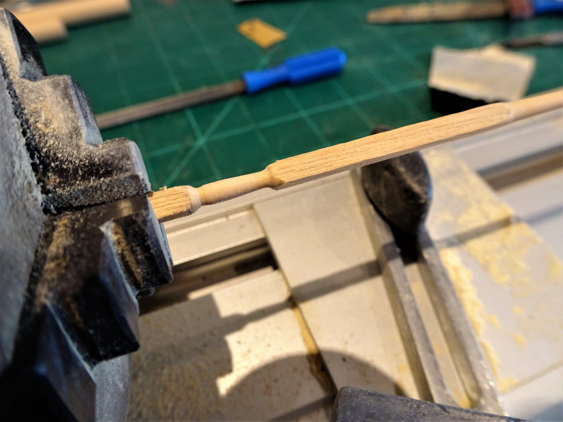
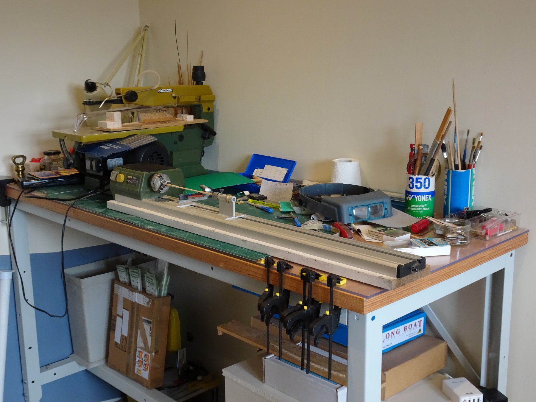
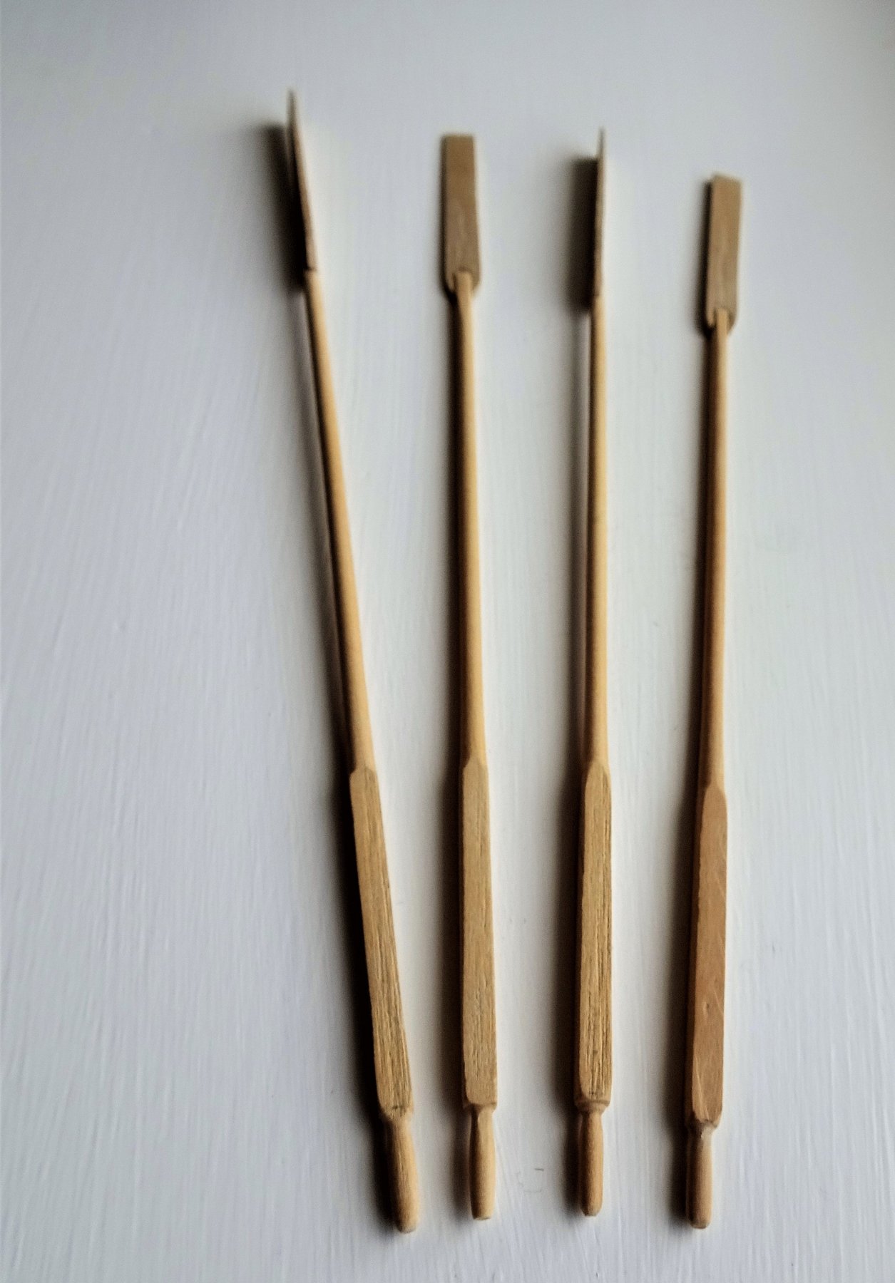
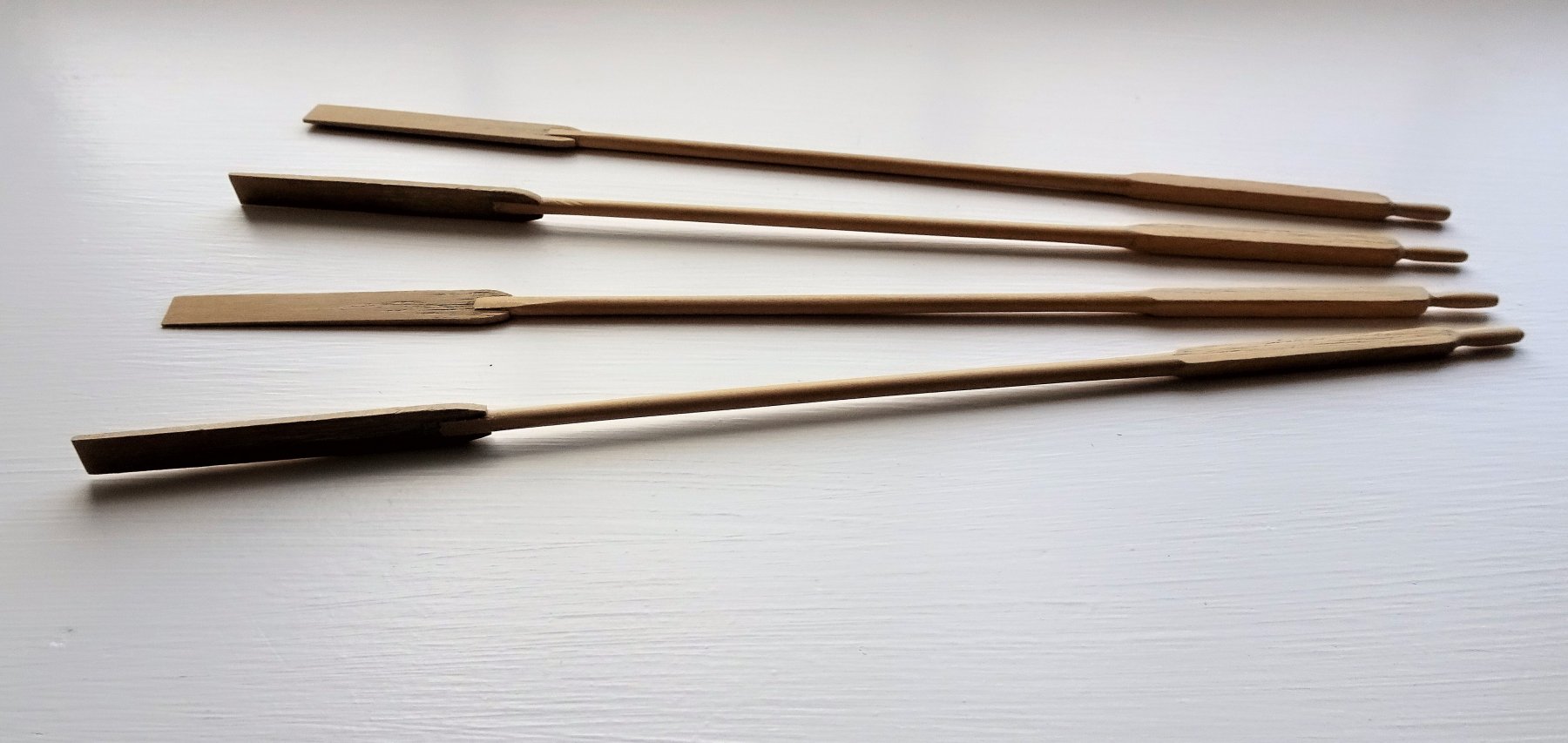
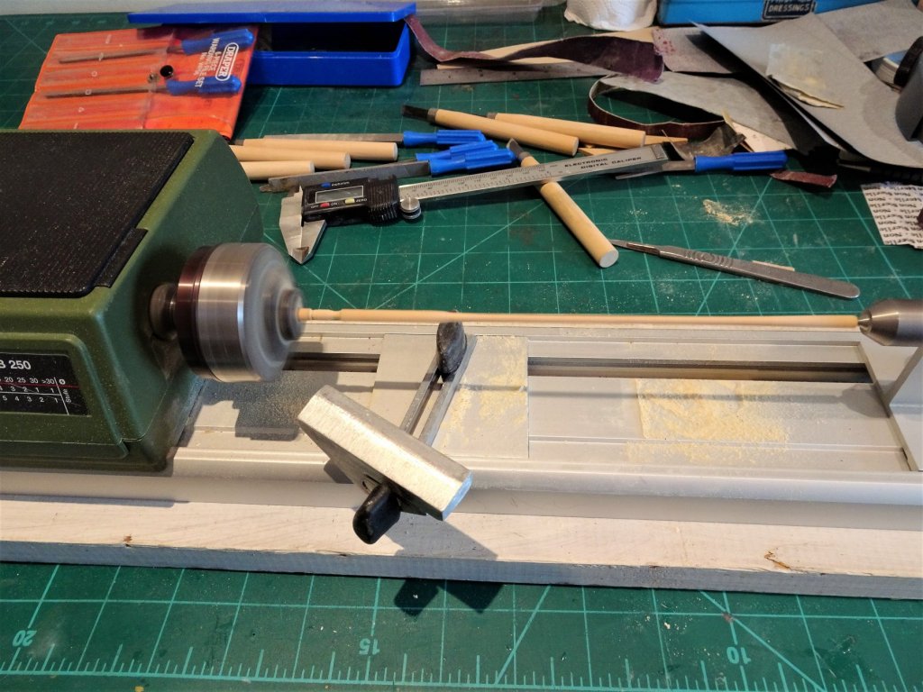
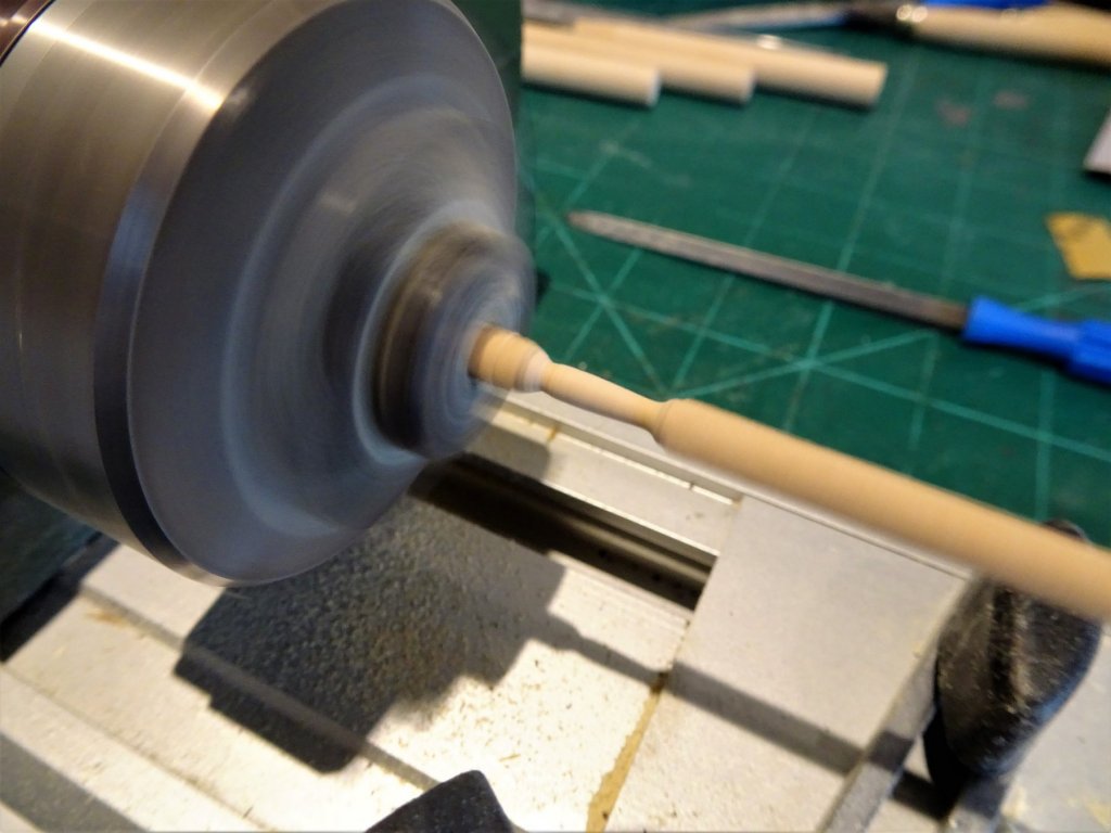
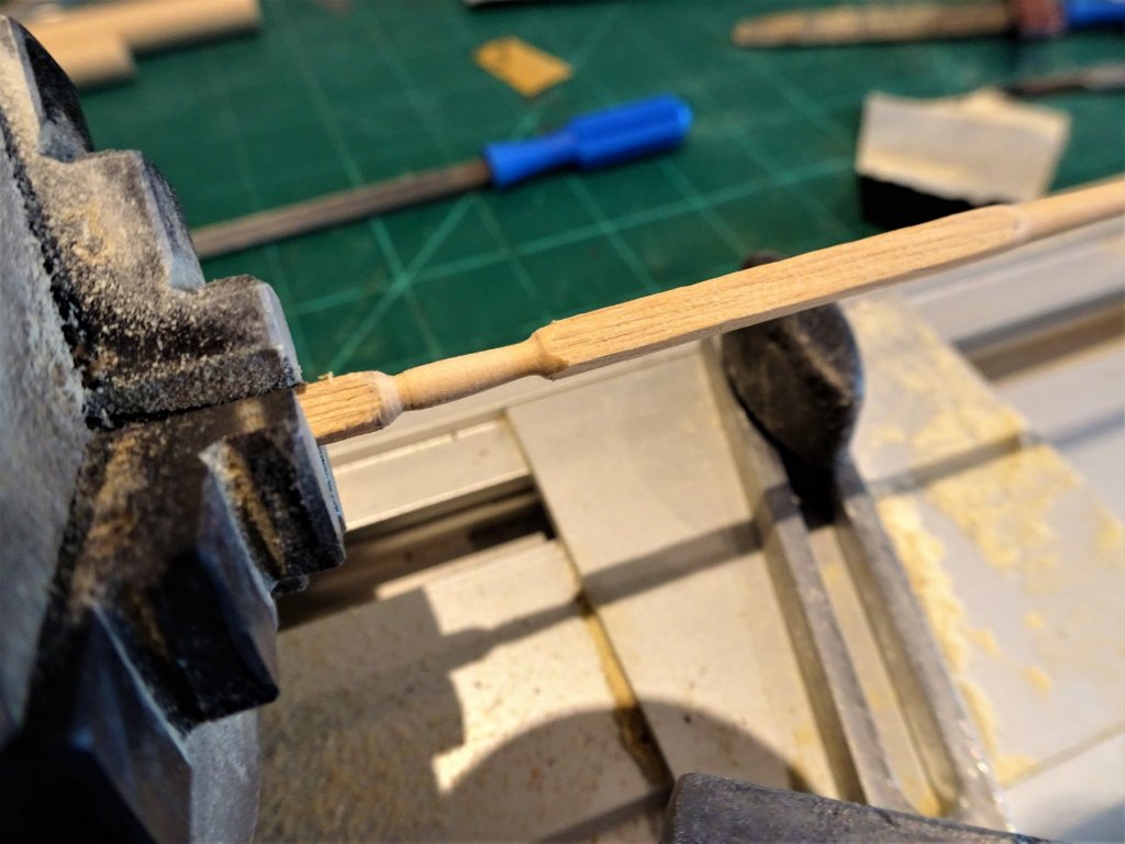
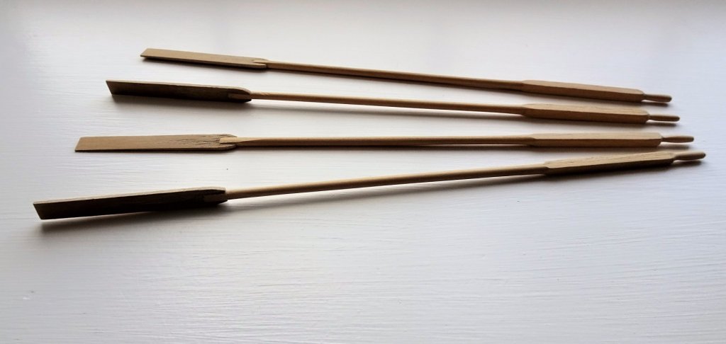
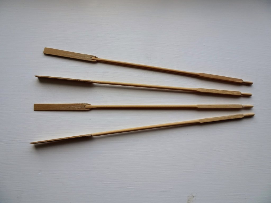
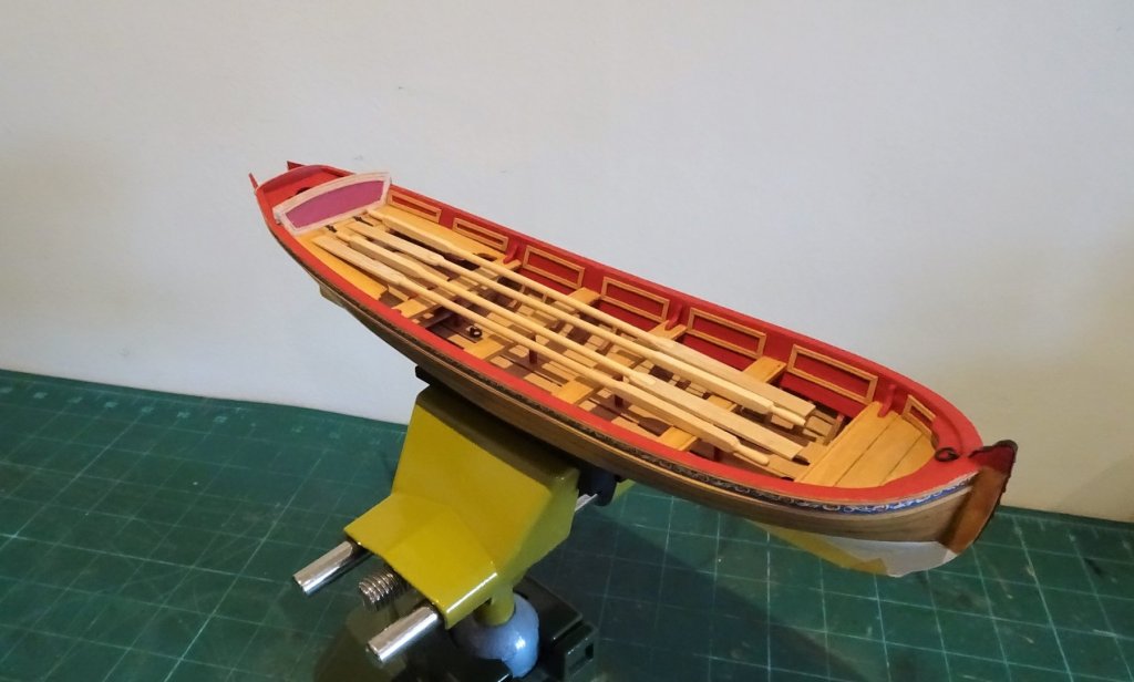
Thanks Bob. Thinking about oars. As a change from working on the boat I decided to make the oars. Our Pinnace is a four oared single banked boat which means the oarsmen sit on the opposite side of the boat to the oars thole pin an arrangement which was common in Pinnace and barges. There are two main references regarding oar specification; David Steel and W.E May's book The Boats of Men of War, which also makes use of Steel's 1797 work. In our model the oar is scaled to 14' 9" For the handles, looms, and body I have used Boxwood 3.4mm square stock The blades will be cut from some Boxwood sheet stuff. 0201 For this the wood lathe is required, not used since I turned the masts and yards for Pegasus. These oars can be made without using a lathe, but it surely makes life easier. 0218 Forming the handle, the Loom is left in the original square profile, although David Steel in his The Art of making Masts, Yards, Gaffs, Booms, Blocks and Oars (1797)notes that The Looms of boats' oars are often made round. 0211 A combination of files and sand paper is used to shape the various parts. 0221. Getting quite crowded on the work bench at present. 0323 0322 0321 The completed set before final sanding. 0325 0326 328 I am undecided at the moment how to decorate the oars, paint them or leave them with a clear finish. All of the contemporary models appear to show the oars painted red overall some with only the Handle left unpainted. As the boat interior is mainly clear I am leaning towards an overall red paint job, but this is not a pressing decision to make. Making the oars has been a pleasant diversion, and one that proved more straightforward than I had initially imagined. B.E.


- 156 replies
-
- 14
-
-
- pinnace
- model shipways
- (and 1 more)
-
A wealth of beautifully executed detail Thomas, a very fine model indeed. B.E.
-
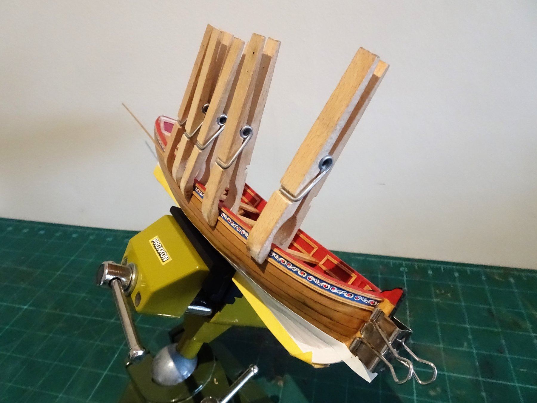
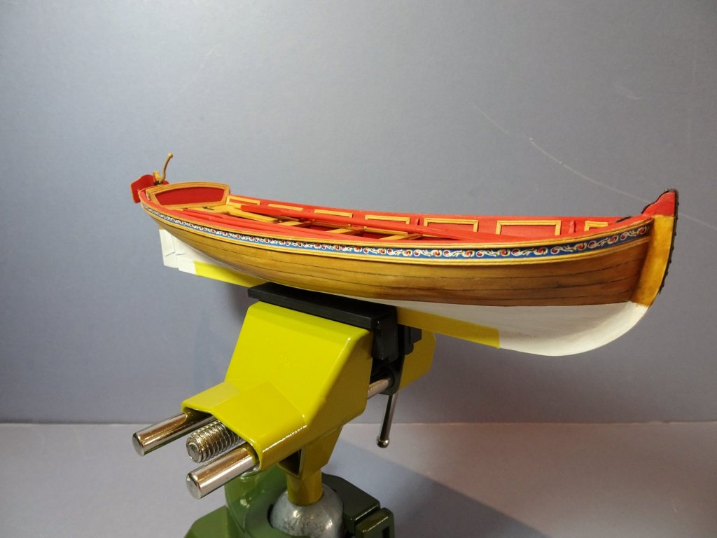
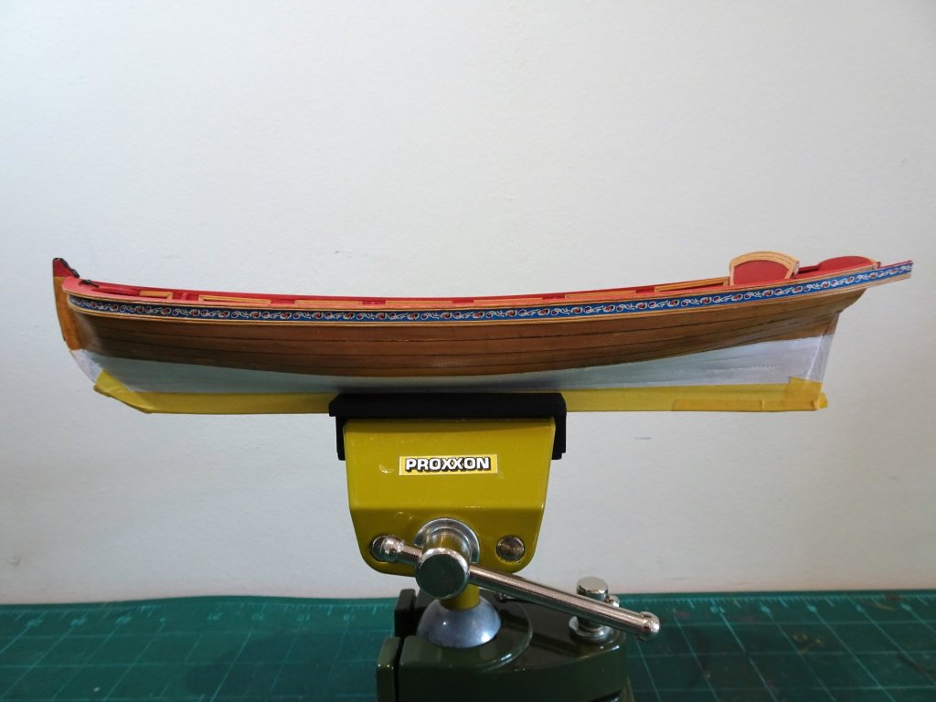
Cheers Don .... movin' on. Next up I added the Friezes along the sheer below the Cap rail. Mrs W provided the Hairspray to 'fix' the ink on the pre printed friezes. This was then applied with pva. Below the Frieze I added a Boxwood moulding; again a profile was cut into the face to match the Cap rail edge. 0172 I pre-bent the moulding to fit around the bow and fixed it using ca. I varnished the strip before fixing to avoid getting any on the frieze. 0234 0237 0247 0258 With the frieze completed I gave it a coat of matt varnish. B.E.


- 156 replies
-
- 16
-
-
- pinnace
- model shipways
- (and 1 more)


.JPG.ef53584232662b8fb1ce2db9e855d49a.JPG)
.jpg.f134bd5969be299ecaf8de42c03df869.jpg)


.JPG.2e2e6c2b65ba56a8dcbe3e61f62af48f.JPG)