.JPG.ca33079f5815b861e67b9c2cccd37982.JPG)

Blue Ensign
-
Posts
4,567 -
Joined
-
Last visited
Content Type
Profiles
Forums
Gallery
Events
Everything posted by Blue Ensign
-
 Nice progress Jason, very pleasing to my eye. B.E.
 -
Having just looked at Rusty's completed Cheerful, two come along at the same time. What a stunning model you have created Mike, beautiful work, and another fine reference for those who follow on. Thank you, B.E.
- 452 replies
-
- 6
-

-
- cheerful
- Syren Ship Model Company
- (and 1 more)
-
Beautiful model Rusty, and great photo's. Fills me with some trepidation as I start out on my own Cheerful journey, but relieved that I have such an example to inspire me. Just one curiosity, why did you display the Union flag at the Gaff, rather than a naval ensign? beautifully fashioned flag by the way. Regards, B.E.
- 310 replies
-
- 2
-
-
- cheerful
- Syren Ship Model Company
- (and 1 more)
-
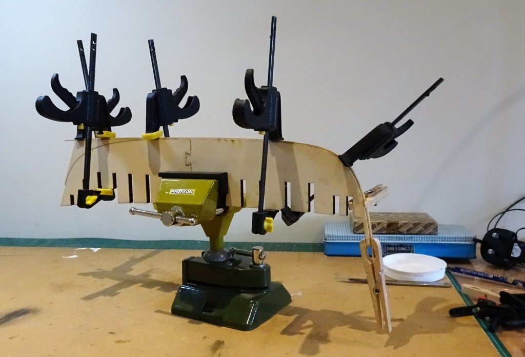
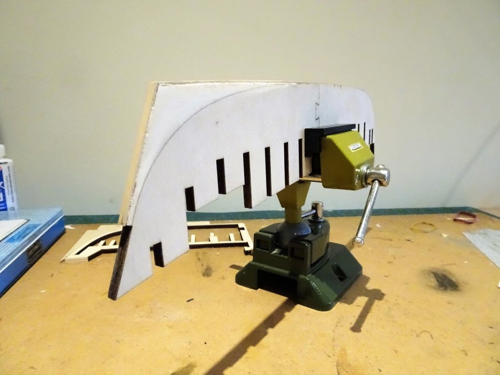
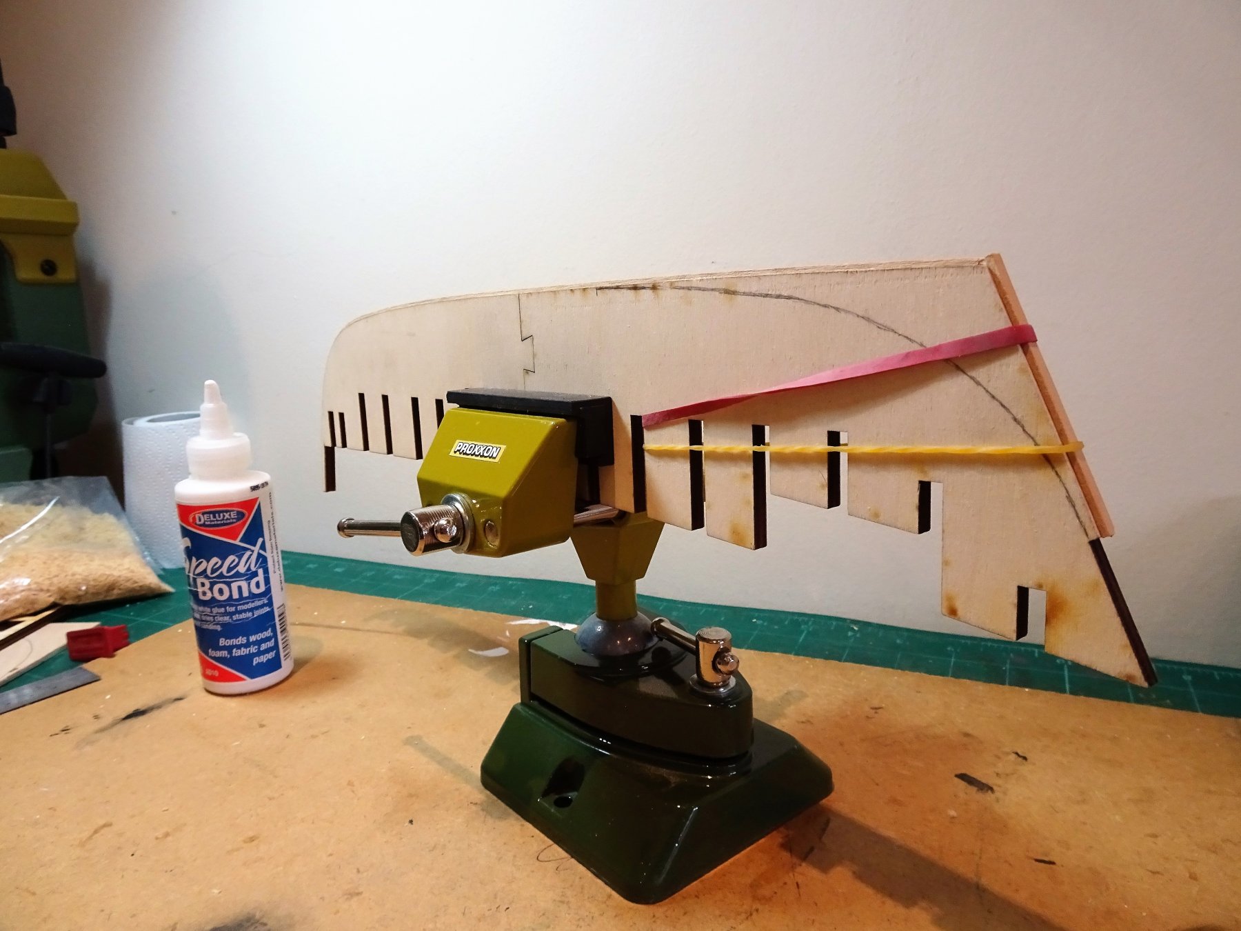
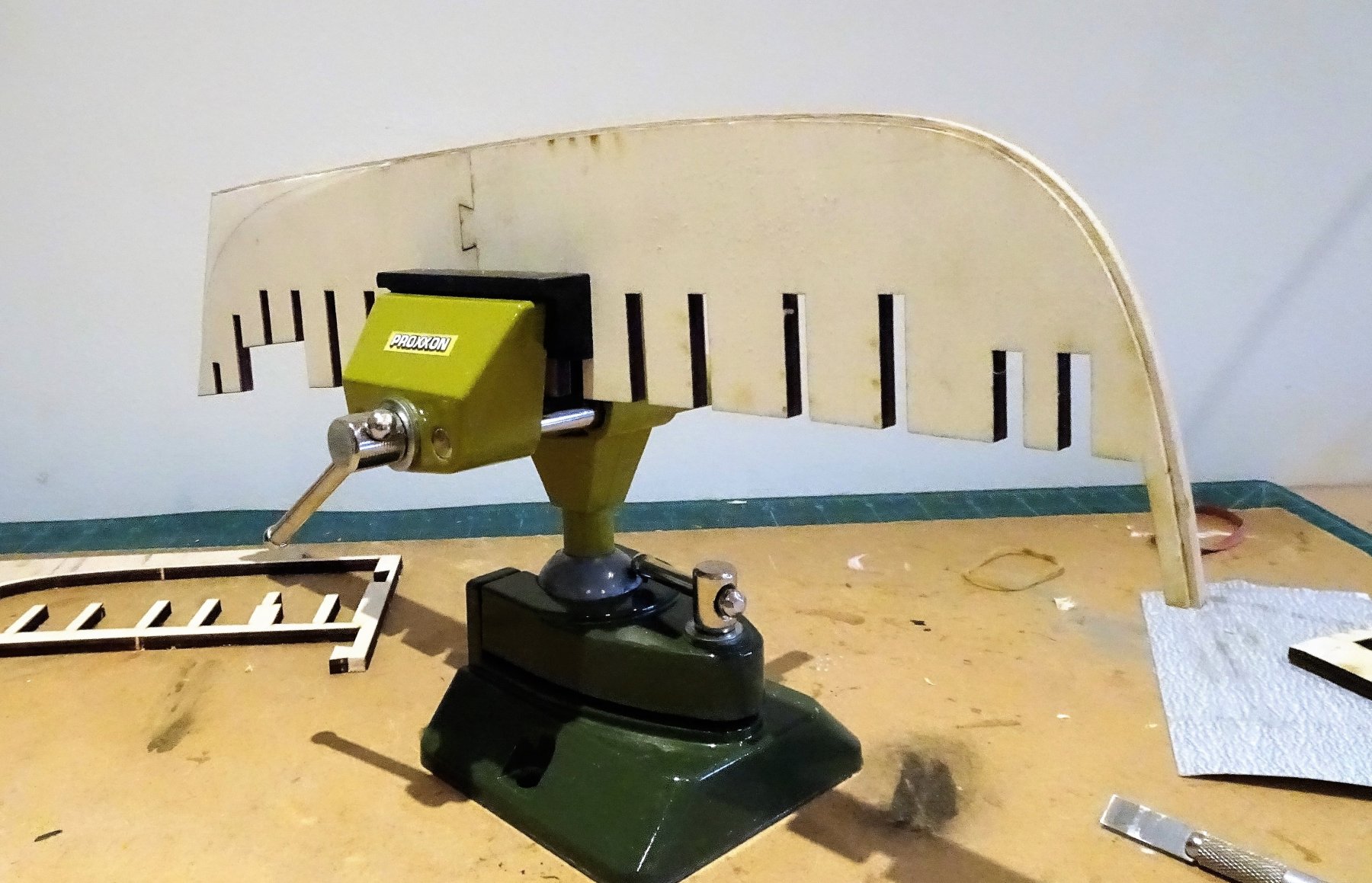
Cheers Kurt, I've got to work So the build begins The two keel halves are glued together and the Bearding line marked on the Starboard side to match the Portside. The Rabbet strip is now ready for fixing. 3112 I used the False keel fret cut out to make a former to shape the rabbet around the bow shape. 3120 Using the wet/heat method I pre-bent the strip to take the stress out when gluing. 3122 Because the strip has to be centred along the keel not having to fight it or apply too much pressure is a great bonus. 3256 Only light clamping is required. 3258 The stern rabbet strip is then added. 3262 and finally the bearding line taper sanded in. 3263 I can now move onto the Boxwood stem and Keel. B.E.
.thumb.JPG.6d0af4ae4d8c9d596e1195243a20c380.JPG)
.thumb.JPG.97e764a123d7cecad2bac9ccc0253fe4.JPG)


- 574 replies
-
- 16
-
-
- cheerful
- Syren Ship Model Company
- (and 1 more)
-
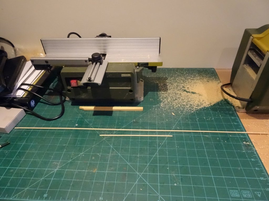
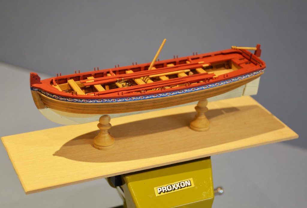
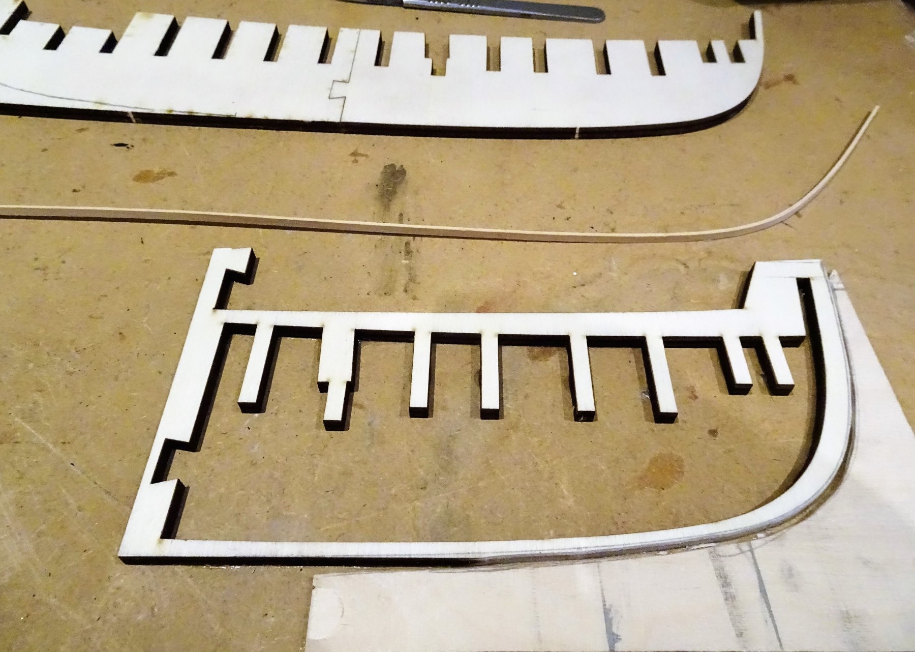
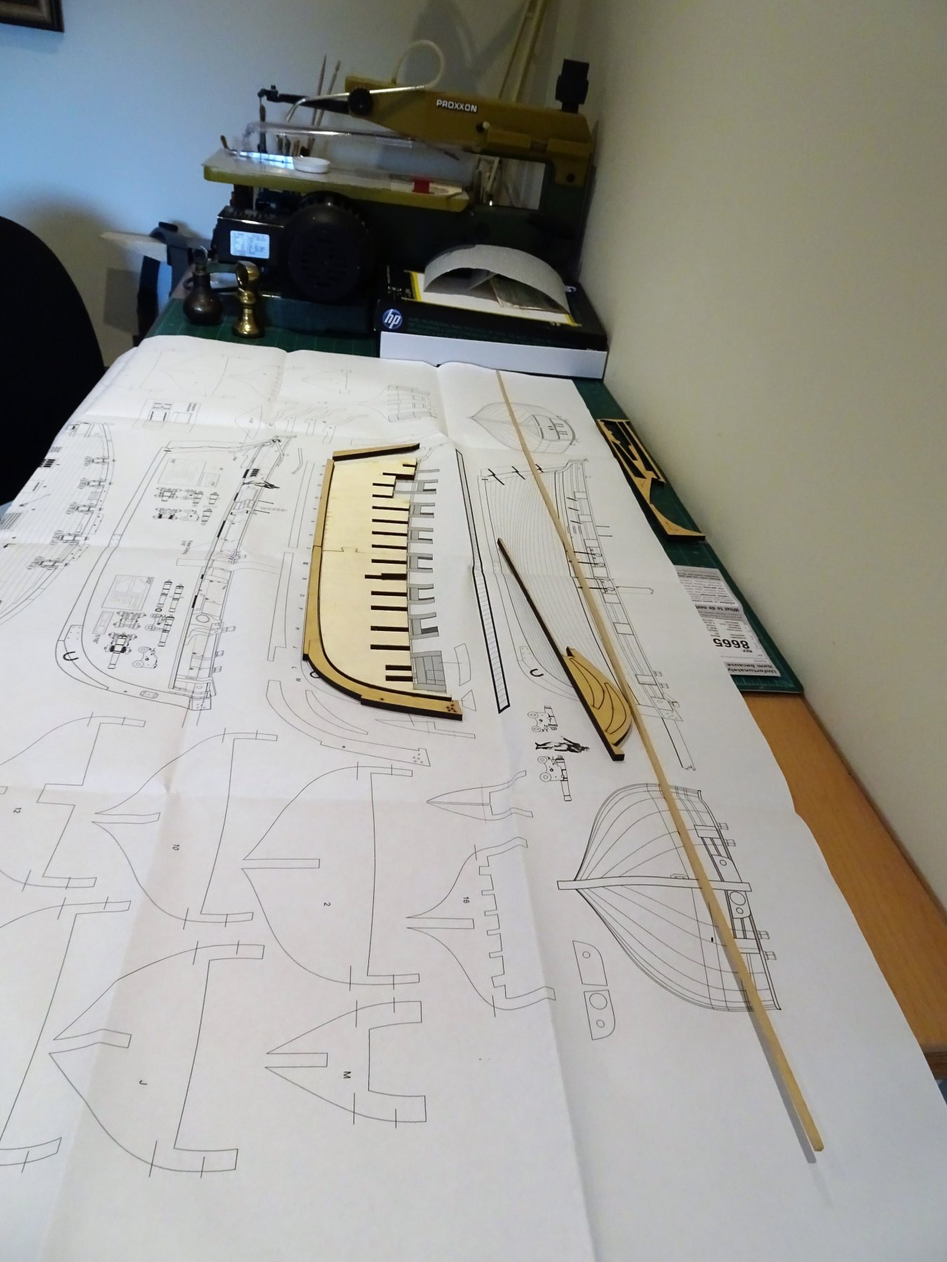
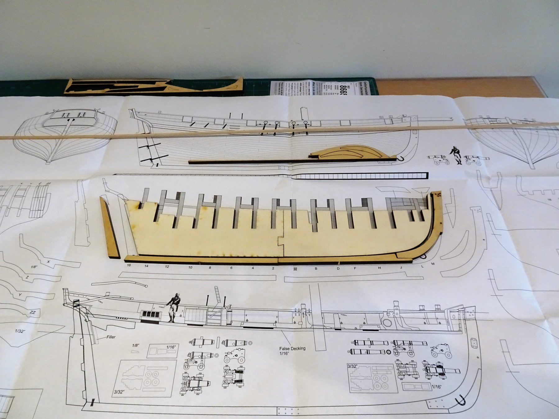
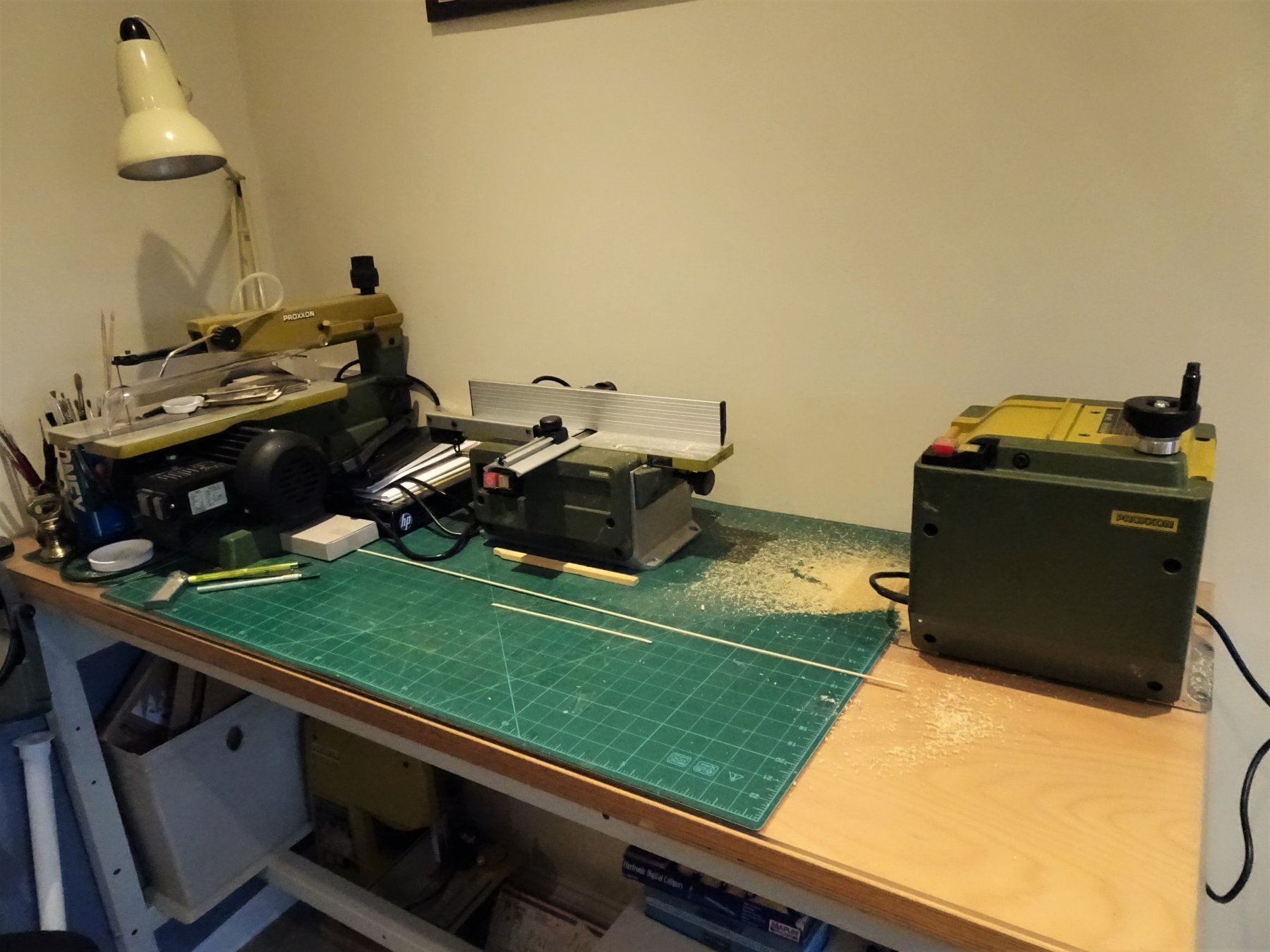
Cheers Guys Well a week or so has passed and nothing really to show, but I have been busy reading logs and I feel grateful for three fine builds by Rustyj, rafine (Bob) and Stuntflyer (Mike) in addition to Chuck's own initial build, to refer to. If I come anywhere close to those examples I will be a happy man. As an aside I have treated myself to a couple of Proxxon goodies to add to my collection. A Thicknesser/sander, (DH40) and a Surface Planer (AH80) plus some spares, and mill bits. As with previous purchases I obtained the machines from Germany. https://www.tbs-aachen.de/ .....and saved myself £118.00 over the UK supply price. I always feel a certain trepidation whenever I start a new build, and I tend to spend a fair bit of time fiddling with the first stage bits before I get the pva out. 3079 Looking at the two false keel halves, they don't seem to join square at both top and bottom. Maybe the tongue of the Jigsaw join is a tad long. 3078 The second task will be to glue a Rabbet strip (⅛" x1/16")- 3.2mm x 1.59mm along the stem, bottom and up the stern of the false keel. This strip doesn't seem to have been provided in the Crown Timber package but they do supply a 1/16"" thick sheet of boxwood which would require a ⅛" strip cutting off. 3104 Fortunately I do have some 3.4mm square Boxwood strip and this provides me with a perfect opportunity to bring my new Thicknesser machine into use. 3103 It brought the 30" length of 3.4mm boxwood strip down to 1.59mm consistently along its length. Being new to this machine I took quite a few light passes to familiarise myself, but I think it will be a very useful addition. A question to those who may have this machine, when feeding narrow strip thro' is it normal for it to move across the planing table without maintaining a straight line? it doesn't seem to affect the cut but is a bit disconcerting to a new user. B.E.

- 574 replies
-
- 14
-
-
- cheerful
- Syren Ship Model Company
- (and 1 more)
-
I'm another fan of the Flower Class Corvette, Adrian, and looking forward to your new project. Were you inspired by the magnificent cut away model made by Barry Sharman? I was lucky enough to see his outstanding work at a model show back in 2012, be good to see how your build progresses. Regards, B.E.
-
Having only just started this build I can only hope that I achieve the cleanness and beauty of the hull you have produced Eric, fine work indeed. B.E.
-
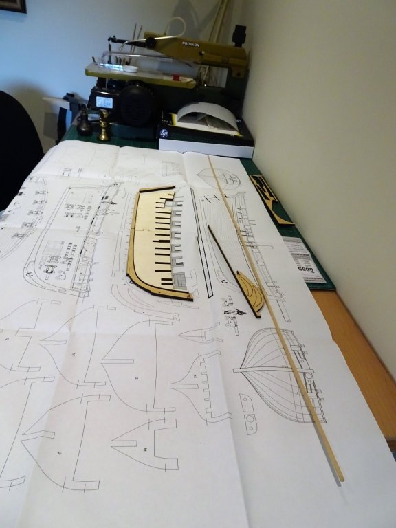
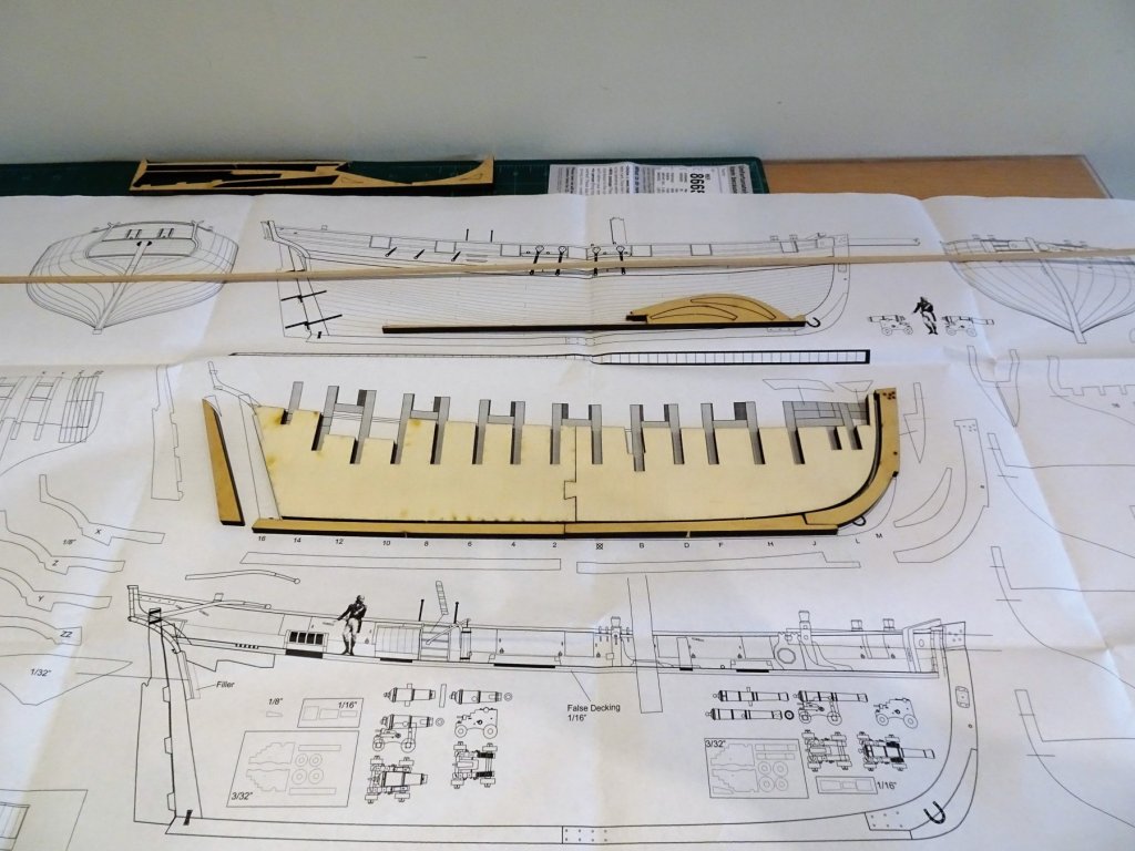
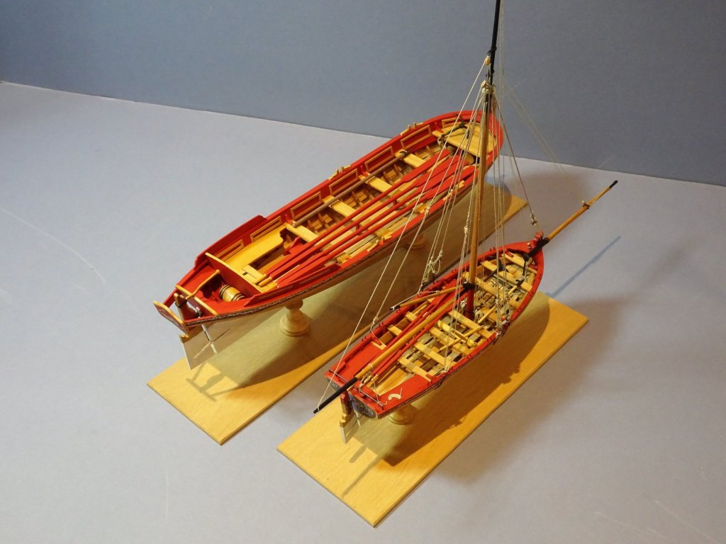
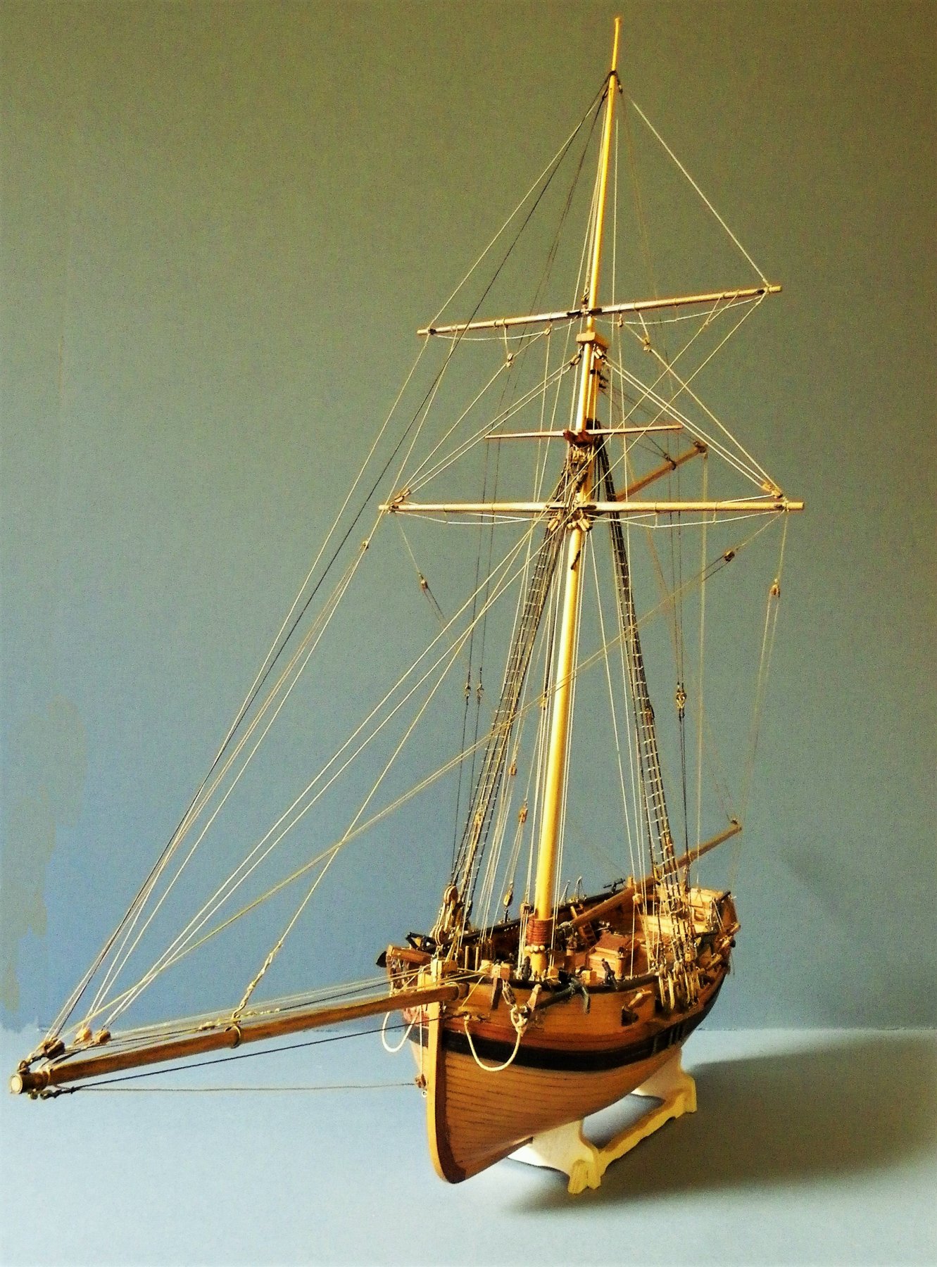
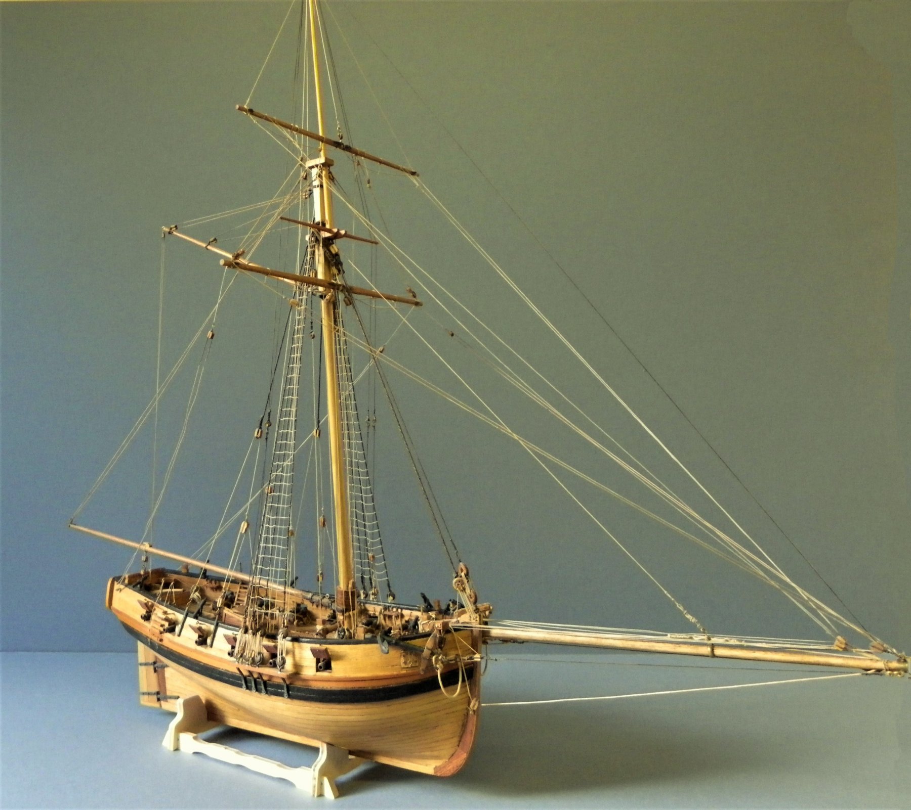
HM Cutter Cheerful 1806- 1816 This is my new project following completion of the Pinnace and Long-boat kits. I have had this offering from Chuck's Syren stable, including the wood set, gathering dust beneath my workbench since 2016, and I have been collecting all the subsequent add-ons, and fittings as they have been issued. So I now have all the makings to hopefully do justice to the fine materials, fittings, and the beautiful plans produced by Chuck. A period now to organise the build, assimilate the instructions and read thro' logs of those who have gone before. A couple of holding pics of my last foray into cutter building some 30 years ago, a bashed version of the Mamoli kit at 1:72 scale. 3070 007 Still on display in my Dining room, uncased, but fairly easy to periodically clean, she remains one of my favourites. Regards, B.E. ps: I did show Mrs W the actual plans of Cheerful and pointed out the actual, not insubstantial size of the beast.; Fazed she was not in the least; what can possibly go wrong with her on-side .

- 574 replies
-
- 23
-
-
- cheerful
- Syren Ship Model Company
- (and 1 more)
-
Thank you Guys for your comments, and for the 'likes' throughout this build, much appreciated. B.E.
- 91 replies
-
- 3
-
-
- 18th century longboat
- model shipways
- (and 1 more)
-
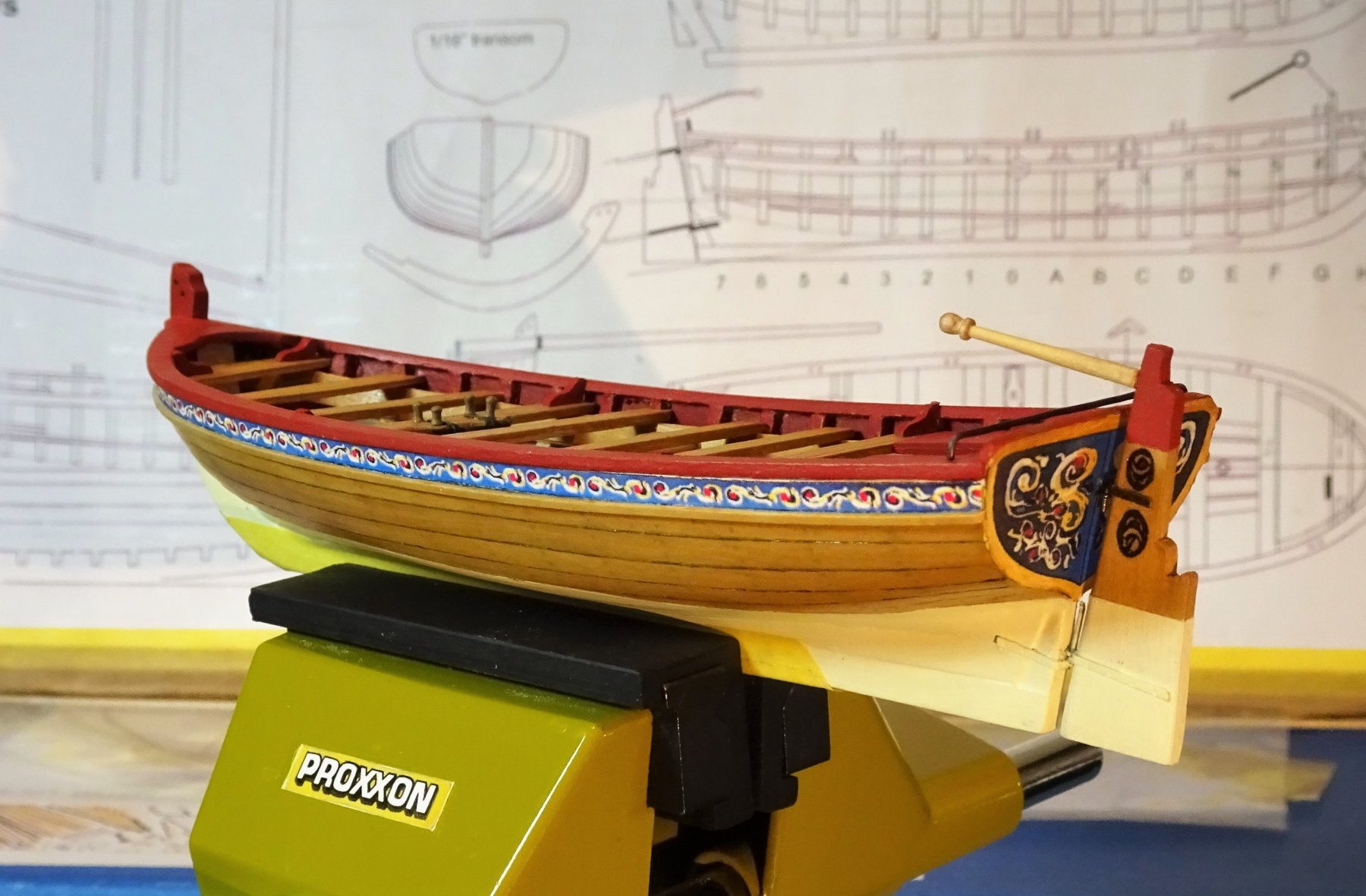
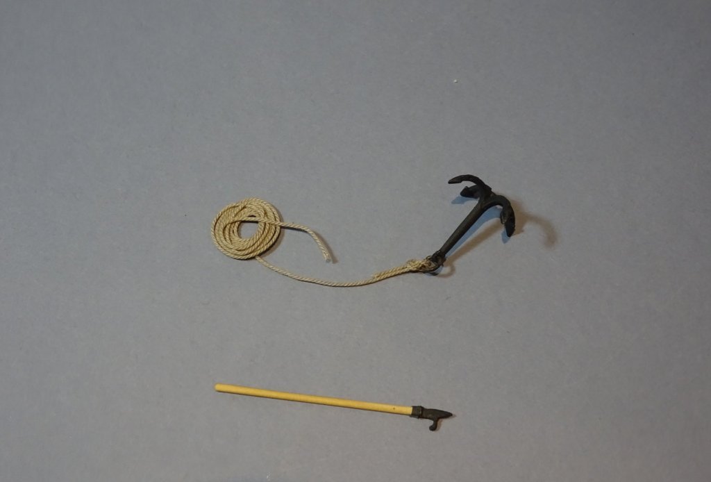
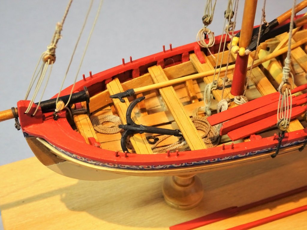
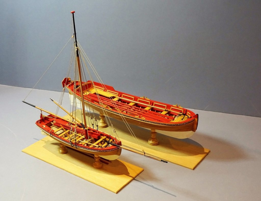
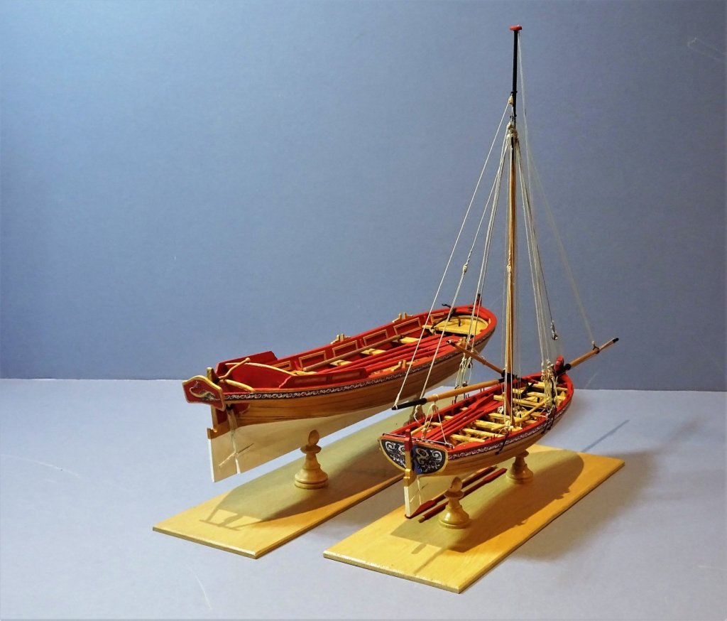
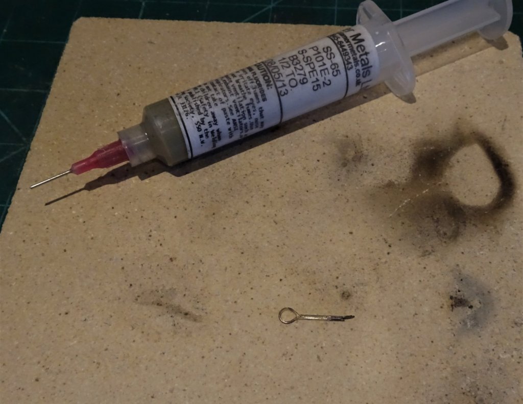
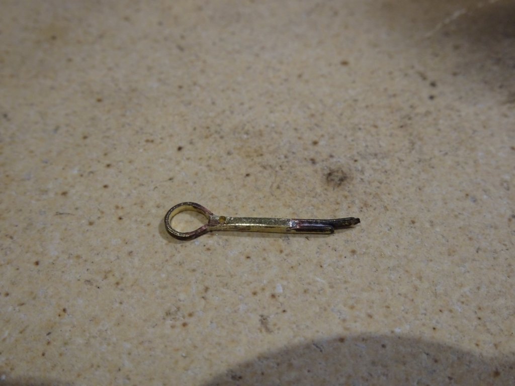
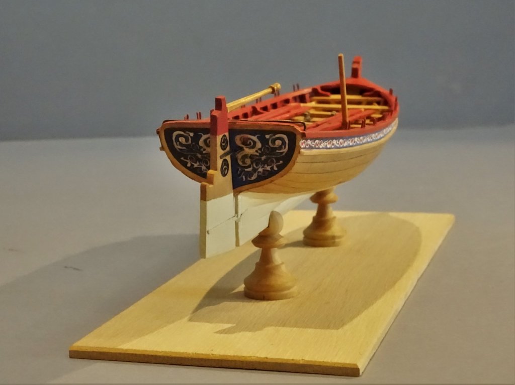
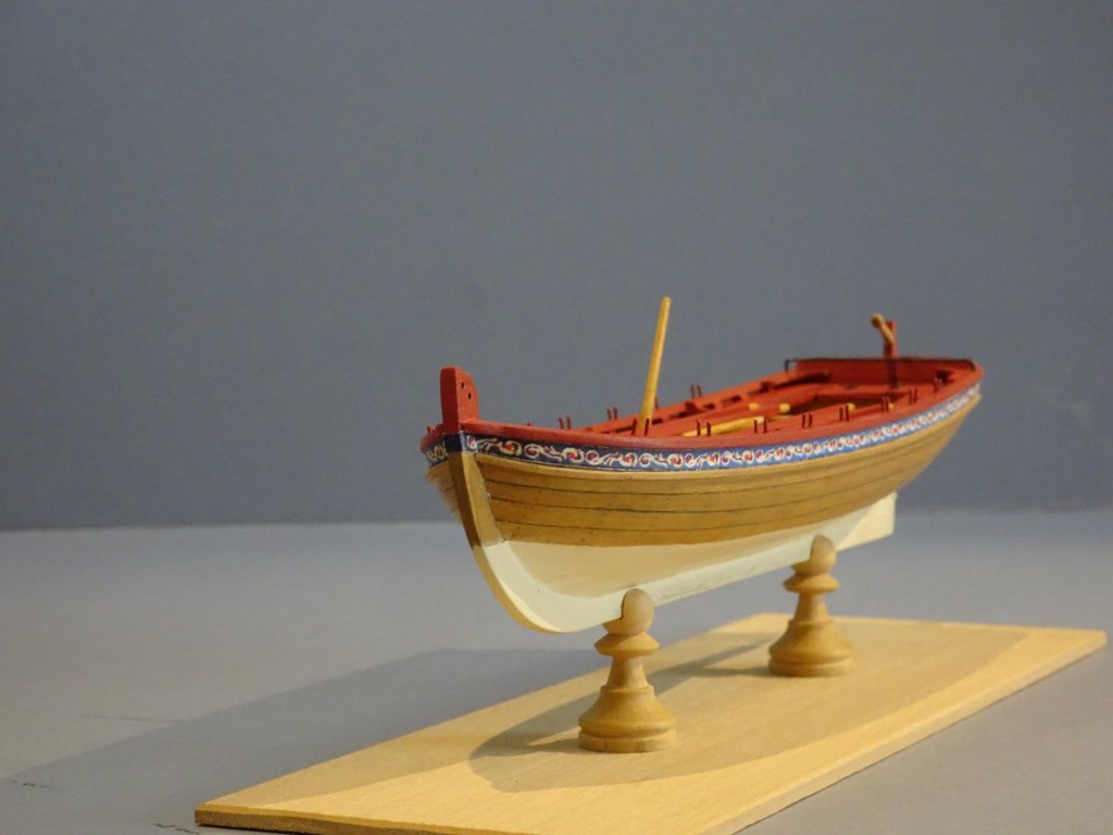
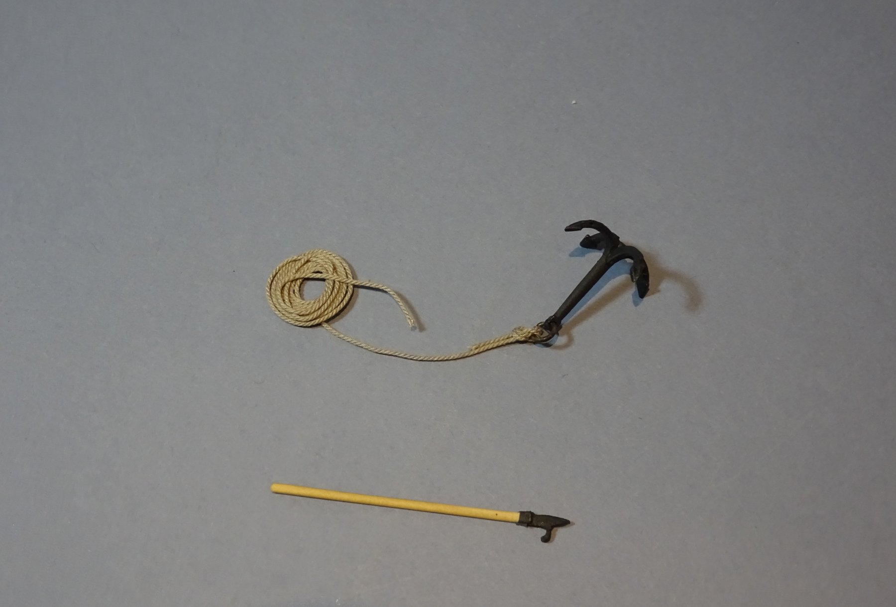
A two month project Completed. Grapnel. The kit provides a soft white metal boat grapnel which at first look seemed somewhat over-scale, particularly in the spread of the claws. Checking against Steel ; A 112lb boat grapnel had a shank length of 3'with length of claws ½ the length of the shank. This equates to scale lengths of 19mm and 9.5mm, pretty much spot on for the provided grapnel, altho' this relates to largest size of grapnel. Even so the curve of the claws seems less pronounced than the version shown in the Medway Long-boat, and therefore takes up more room. As with the Pinnace version I added a ring thro' which a 300mm length of 0.63mm Ø line was attached with a Fisherman's Bend. Boat Hook Not provided in the kit, but at least one would have been provided as basic boat equipment. 2777 As with the Pinnace version I knocked one up from a soft metal hairgrip and a length of Boxwood square stock. Completion photo's. 2784 2786 2787 2788 2789 2790 2791 2792 I have now made both of the Model Shipways 18th c boats, and there is a lot of modelling to be had from these two little modestly priced kits and fine little models to be had as a result. 2793 2797 2798 They are also excellent for skill honing particularly in terms of single plank hull planking, and simple ironwork fabrication. It helps if you can replace some of the rather poor Limewood strips and use Syren replacement rigging line and blocks etc. which the kits really deserve. My thanks once again to Chuck for making this possible and I look forward to the issue of his latest small boat offering. B.E.

- 91 replies
-
- 18
-
-
- 18th century longboat
- model shipways
- (and 1 more)
-
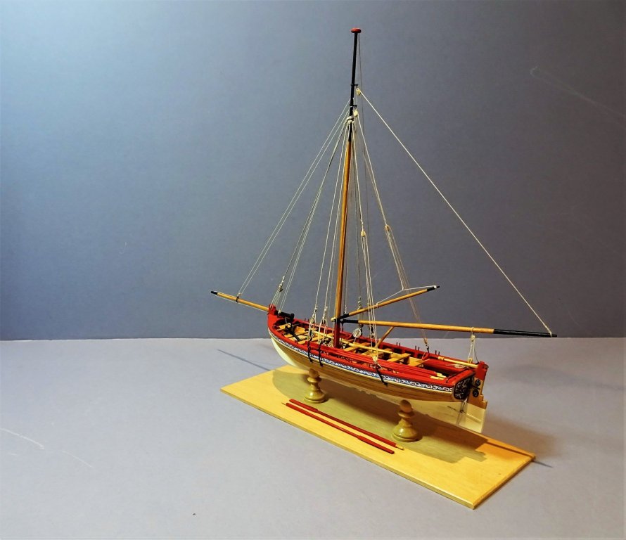
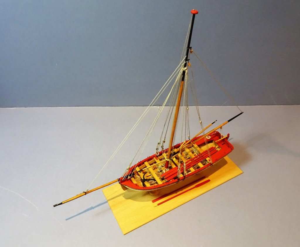
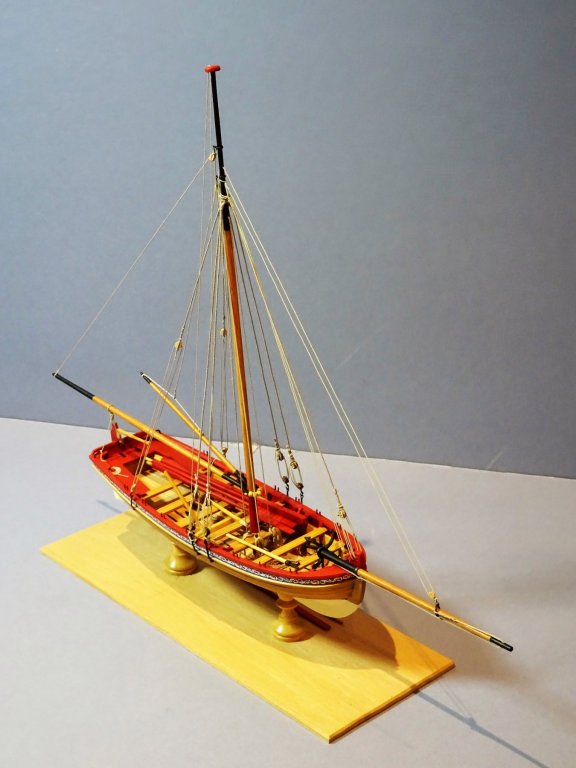
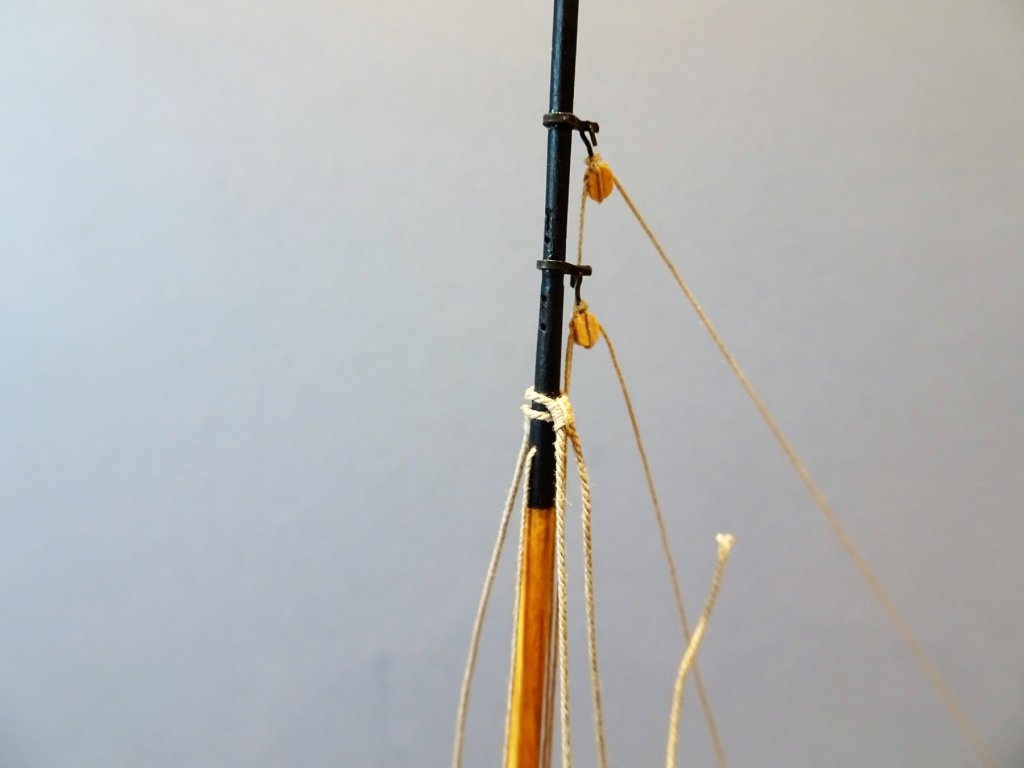
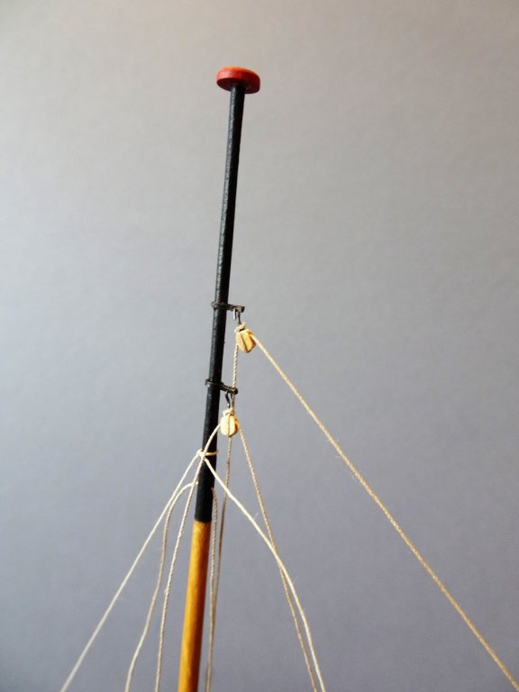
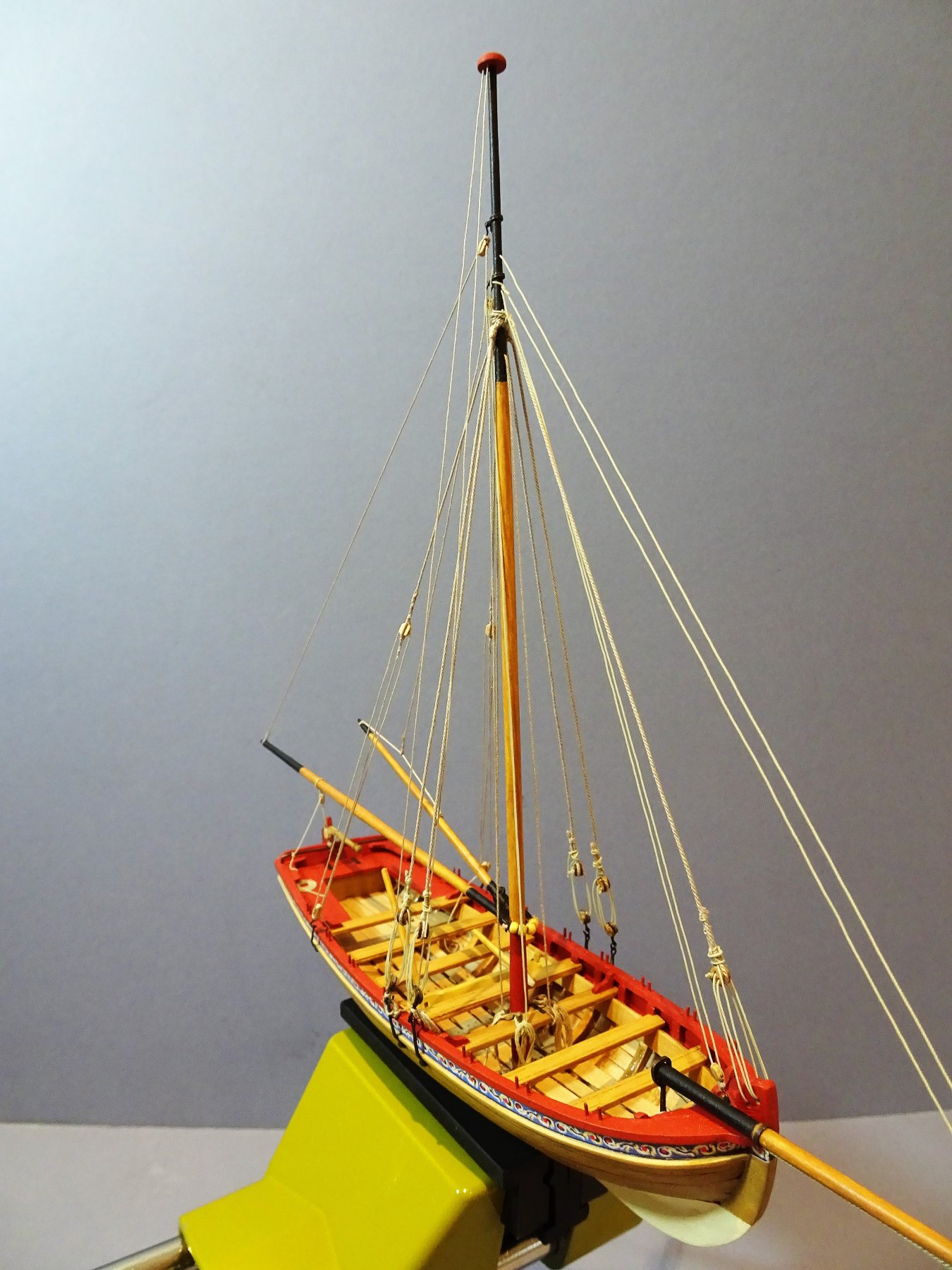
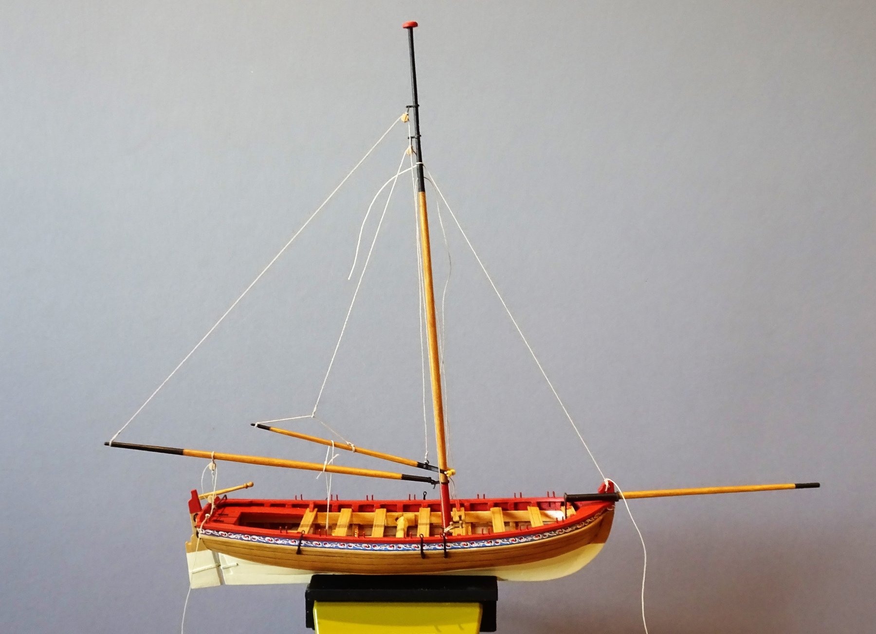
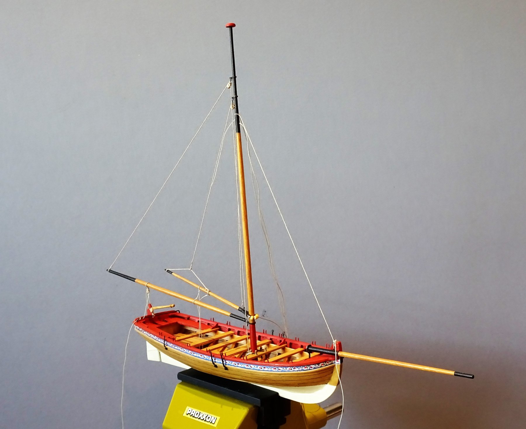
You may very well be right Martin I viewed these two builds as a refresher before I started Chuck's Cheerful, but that may be pushed back in the light of Chuck's new offering the Queen Anne style Barge, which has me sorely tempted. The final stretch. Rigging the shrouds. I decided not to darken the shroud line. 2642 Using Syren 0.63mmØ line the first starboard pair were secured around the masthead using a needle to hold them in position whilst I did the seizing. 2645 For the seizing I used 0.20mm line. The port side pair were then added. For the lower deadeyes I use Chuck's self assembly 3mm ones, and 3mm slightly modified brass hooks. I have gone for the 'quick release' shroud attachment rather than strop the deadeyes in a Chainplate ring. 2649 I also made a 'deadeye claw' as shown in the instructions, mainly to hold the deadeye assembly together whilst I got the shroud around the upper deadeye. 2664 Even so it was a fiddly exercise. From this point on it was a fairly straightforward exercise to put the remaining rigging lines in place altho' I don't tie off the lines as I go along except for the ones around the Mast thwart. 2677 The Jib outhaul completed. 2666 Forestay rigging. Masthead rigging. I found that when I came to tighten the shroud deadeye lanyards that the shrouds had slipped down the mast somewhat. To counter this I inserted a pin thro' the mast below the Masthead shroud rigging. 2676 Line belaying completed, separate coils were made to hang over the pins. 2681 Flag Halyard The kit indicates 0.12" line but this seems a little heavy; a 1" or ¾" circ line scaling to 0.17mmØ seems more appropriate to me. I used Syren 0.20mmØ line. 2672 Nearly at the end now, some fussing about with the detail, and oars and grapnel to place. B.E.


- 91 replies
-
- 10
-
-
- 18th century longboat
- model shipways
- (and 1 more)
-
Thanks for looking in Derek - there were times early in the build when I thought about sinking mine too Thanks Michael, at least we have the new log lists per boat type at the head of this section to better locate builds (thanks to Danny) and this one won't extend beyond three pages or so. Cheers Steve, in the home straight now B.E.
- 91 replies
-
- 4
-
-
- 18th century longboat
- model shipways
- (and 1 more)
-
Nice job on those guns Bob, the carriages look excellent. B.E.
- 682 replies
-
- 5
-
-
- halifax
- lumberyard
- (and 1 more)
-
Great shots of the Bowsprit rigging Michael, those crowsfeet look excellent. Re drilling holes in awkward places have you considered gluing a drill bit in a length of dowel to gain access? Cheers, B.E.
-
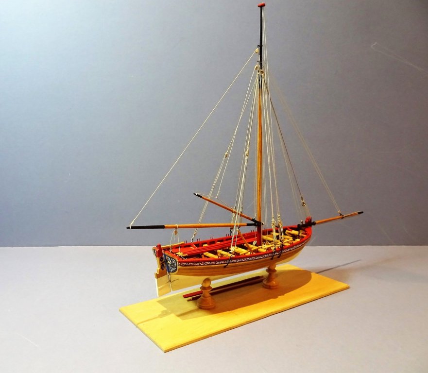
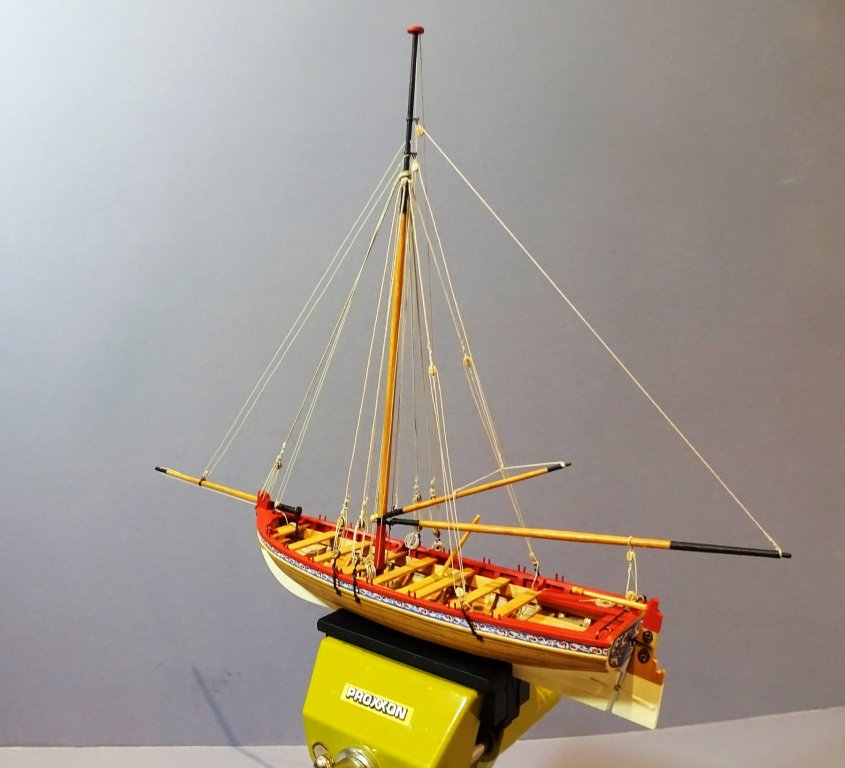
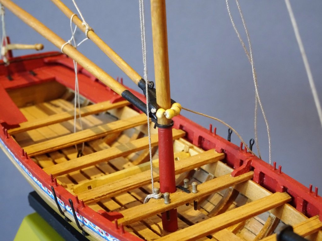
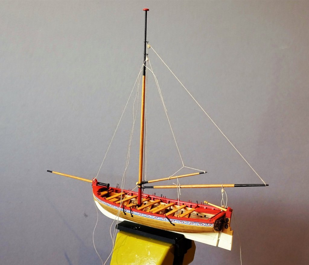
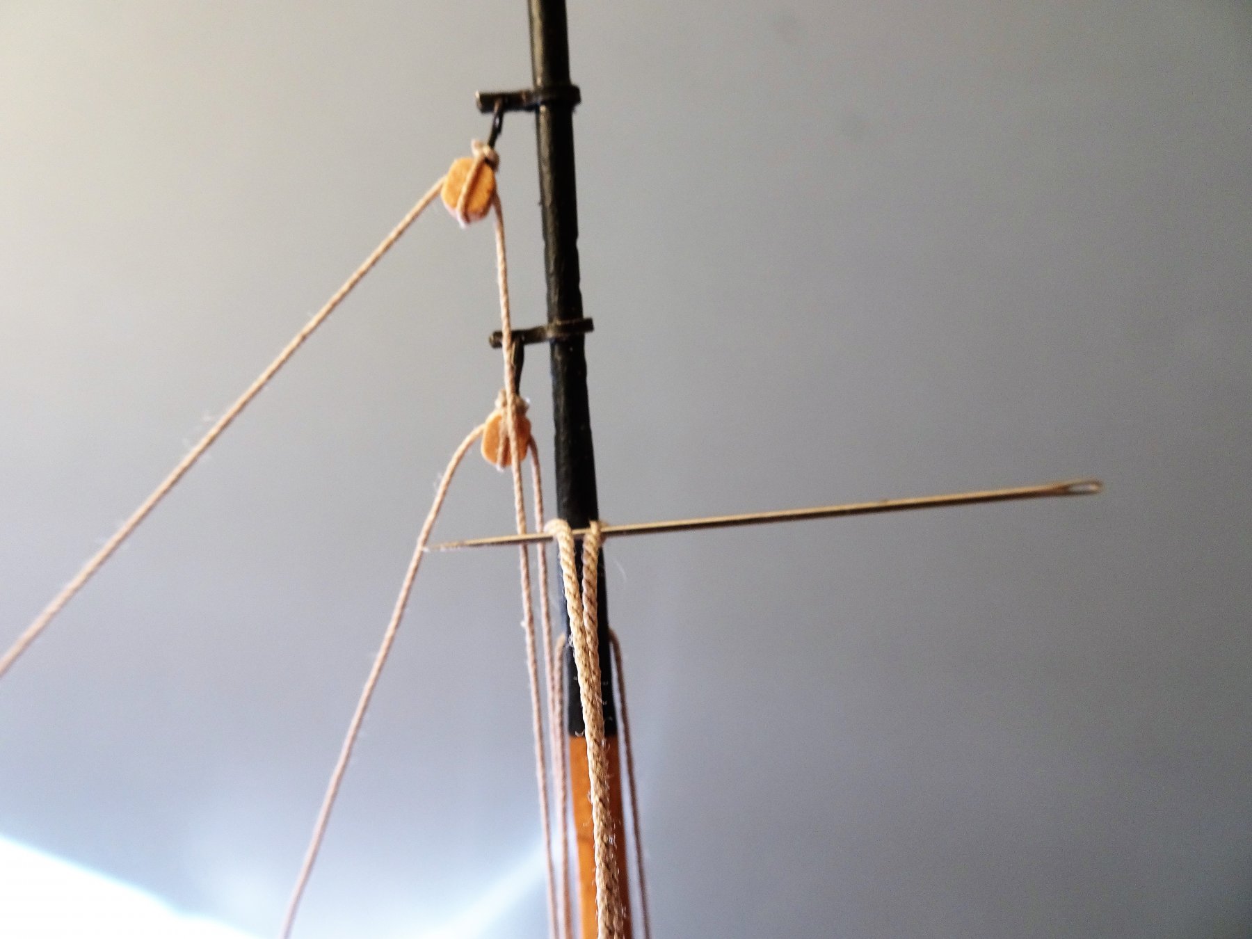
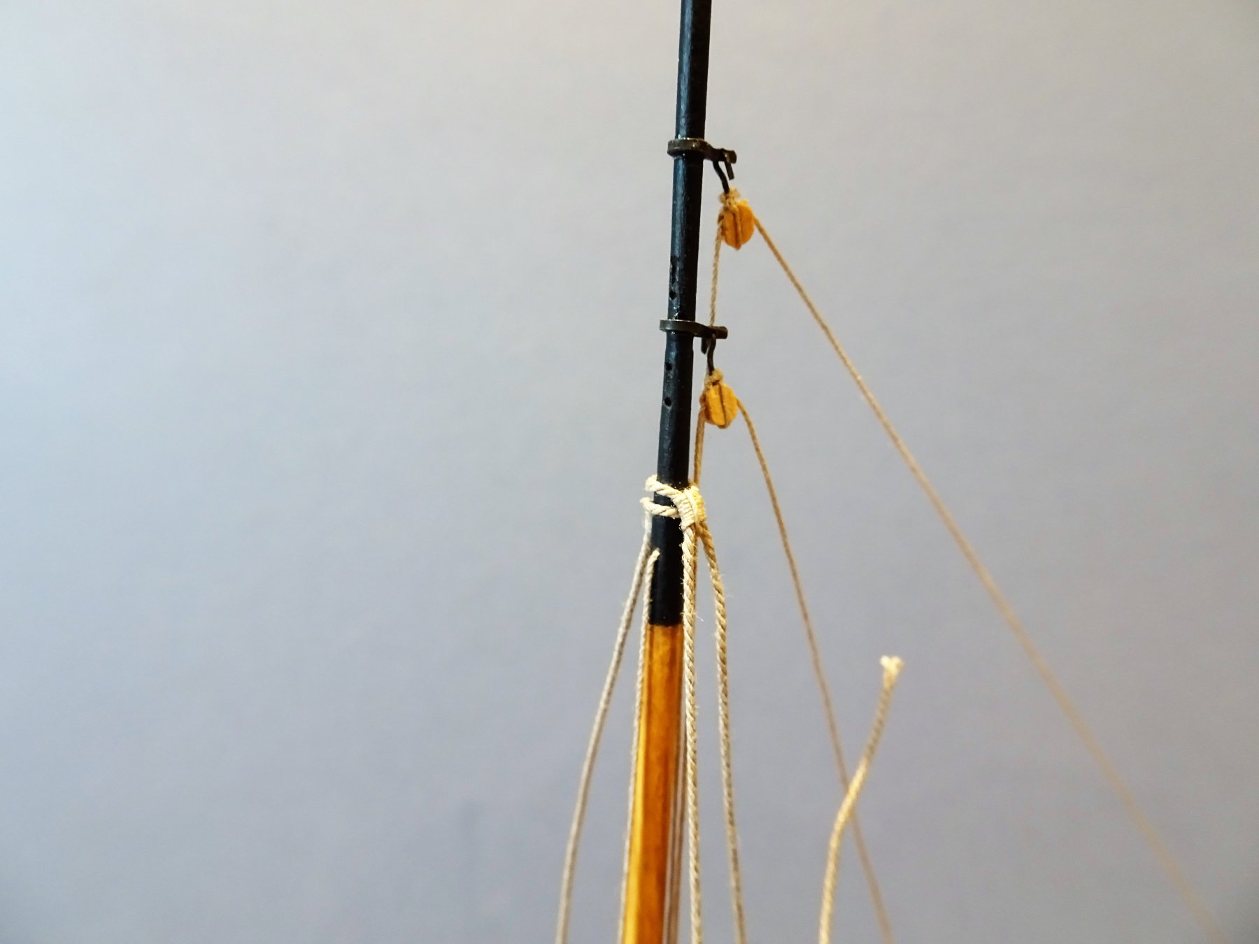
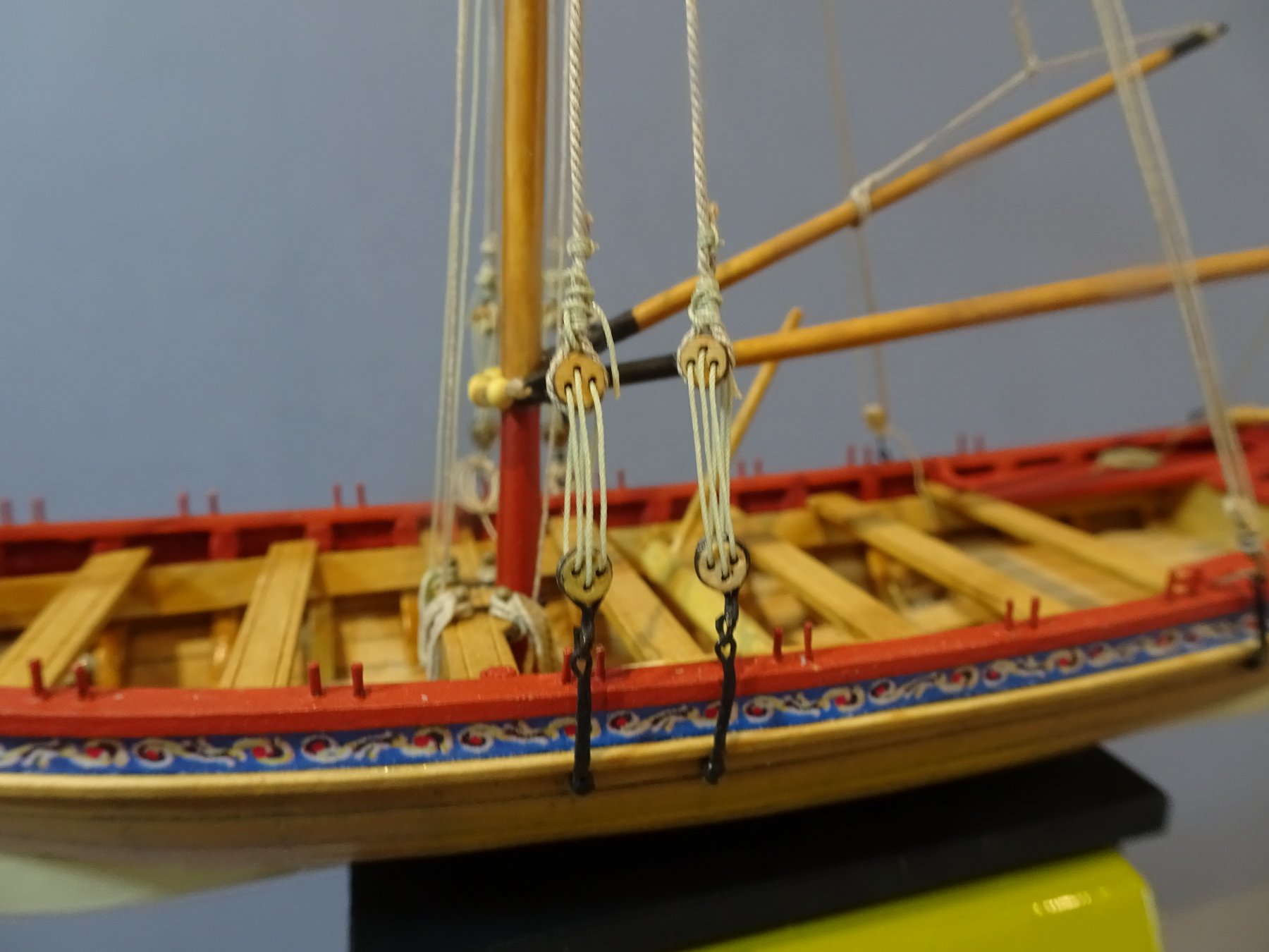
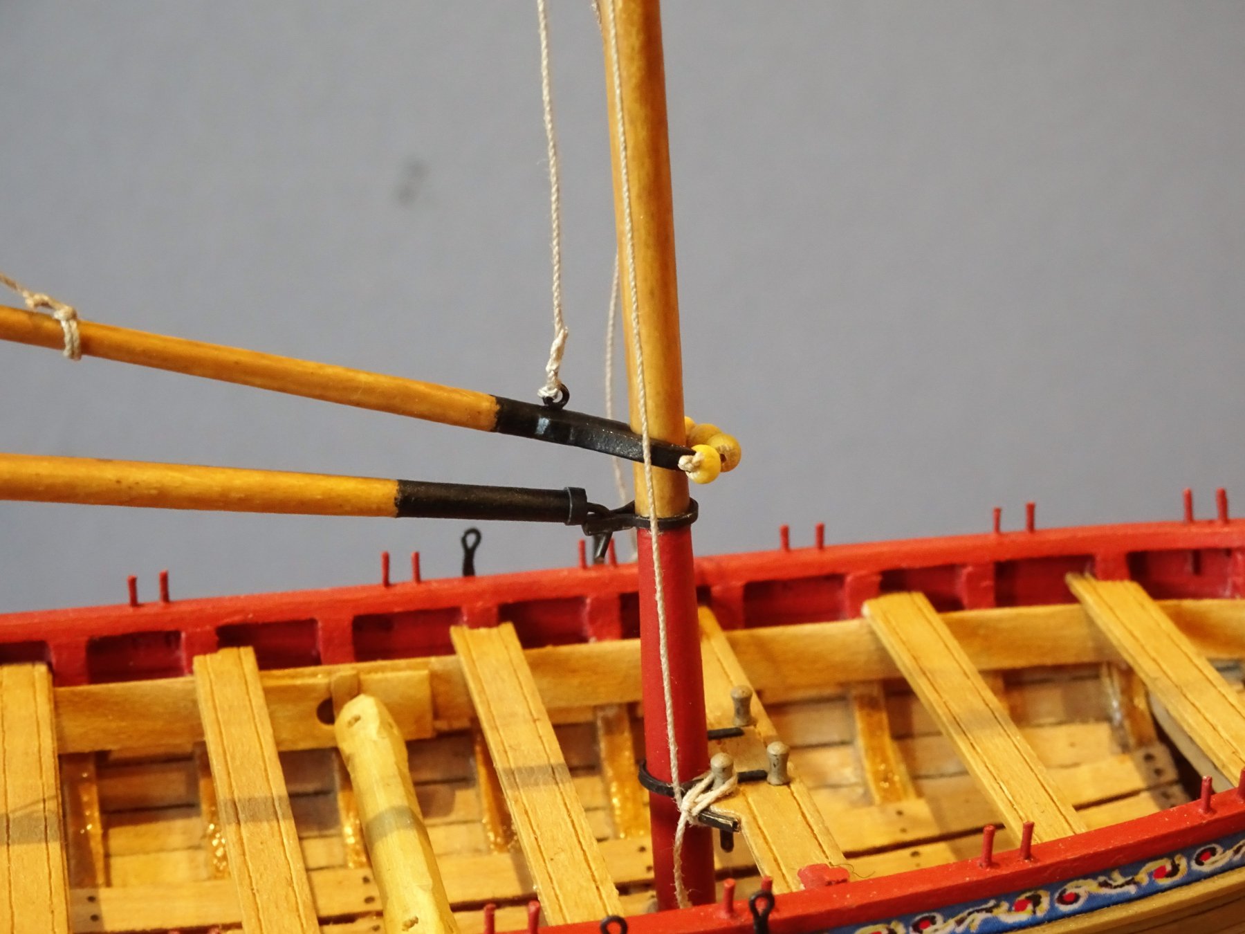
Rigging the Longboat I put the supplied rigging line aside, seems under-scale and I didn't like the look of it, black too black and tan too shiny. The black line was supplied presumably for the shrouds and stay, but would these items be heavily tarred on small boats where the rigging would be taken up and down regularly? in any case the stark black line didn't look good to my eye. The kit instructions mention two line sizes only; 0.012" and 0.018" (0.30mm and 0.45mm Ø ) The instructions don't seem to specifically mention the size for the shrouds but I found on Chuck's log mention of 0.021" line (0.53mm Ø) which is the third supplied line in the box These equate to 1.7" 2.7" 3.2" circ line at full scale. Chuck comments - No....you should use smaller rope to seize the .021 rope around the mast. Use smaller .008 or .012 black for that. The rope is .021 because Expo doesnt have anything else other than really large rope above that size. My .025 brown line is perfect size for the shrouds. But for the kit they have to supply only what they have available. Chuck Chuck's 0.025" (0.63mm) line equates to 3.74" circ at full size. W.E May's book The boats of men of war gives Steel's 1794 rigging table for boats, in relation to ship rates. From this table I have calculated the rigging sizes for our model. Not a direct correlation for a given size of Long- boat and Steel does not mention the use of Running Backstays in relation to Long-boat rigging. Rigging item size circ scale mm Ø line used. Shrouds 3½" 0.59mm 0.63mm deadeye 5" Ø 2.64mm 3mm Lanyard 1½" 0.25mm 0.25mm (Morope) B'stay pendant 2½" 0.42mm 0.45mm B'stay tackles 1½" 0.25mm 0.20mm Fore Stay 4" 0.67mm 0.63mm Deadeye 5" Ø 2.64mm 3mm Lanyard 1½" 0.25mm 0.25mm (Morope) Halyard 1½" 0.25mm 0.20mm Sheets 1½" 0.25mm 0.25mm (Morope) Single block 6" 3.17mm 3mm Topping Lift 1½" 0.25mm 0.30mm Peak Halyard 1½" 0.25mm 0.30mm Throat Halyard 1½" 0.25mm 0.30mm Jib Halyard 2" 0.33mm 0.30mm Jib outhauler 2½" 0.42mm 0.45mm Single block 7" 3.7mm 3.50mm Boat Rope 7½" 1.26mm 1.14mm Grapnel rope 3½" 0.59mm 0.63mm Painter 3½" 0.59mm 0.63mm The line, blocks, and deadeyes, used in each case are Syren, except where otherwise noted. The first item of rigging is the Topping lift for the Boom. This is spliced around the Boom end taken up thro' the top block on the mast and down to belay on the aft s/b side thwart pin. The boom sheet runs between two blocks one on the boom the other seized to the iron horse. I used Morope 0.25mm line for this. 2626 The mast is quite slender and to avoid pulling it out of vertical when adjusting the lift and sheet lines I found it useful to rig a temporary forestay to counter the pull of the sheet. I have also rigged a temporary line to hold down the Gaff whilst rigging. 2635 I used 1/8" Syren blocks for the Topping lift and Peak Halyard lines, hooked to the masthead rather than seized. 2624 Peak Halyard secured to the Gaff. 2623 I used Boxwood Parrel trucks to rig the Gaff. 2627 2631 It is relaxing to be engaged with such a simple rig for a change. B.E.


- 91 replies
-
- 13
-
-
- 18th century longboat
- model shipways
- (and 1 more)
-
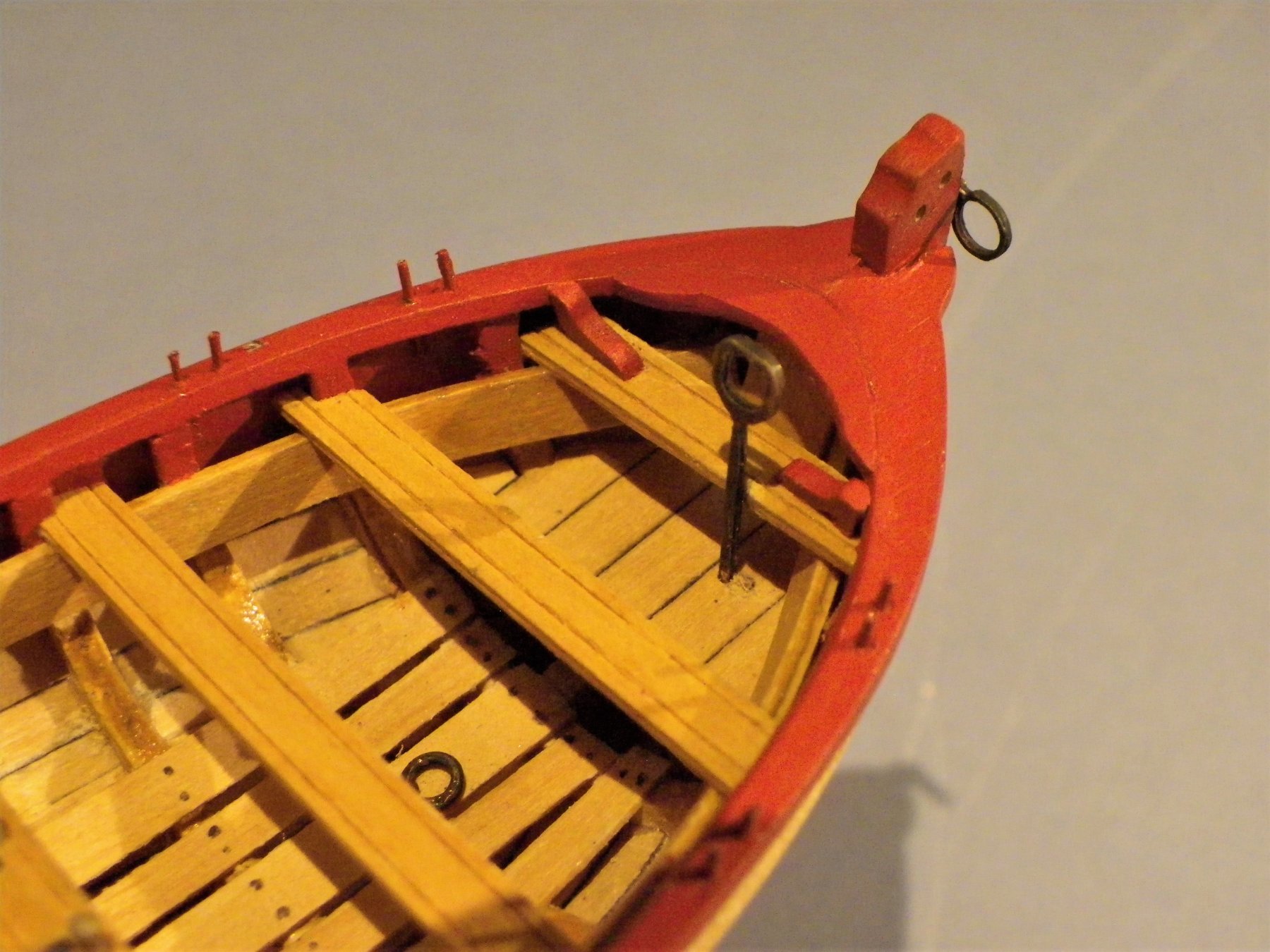
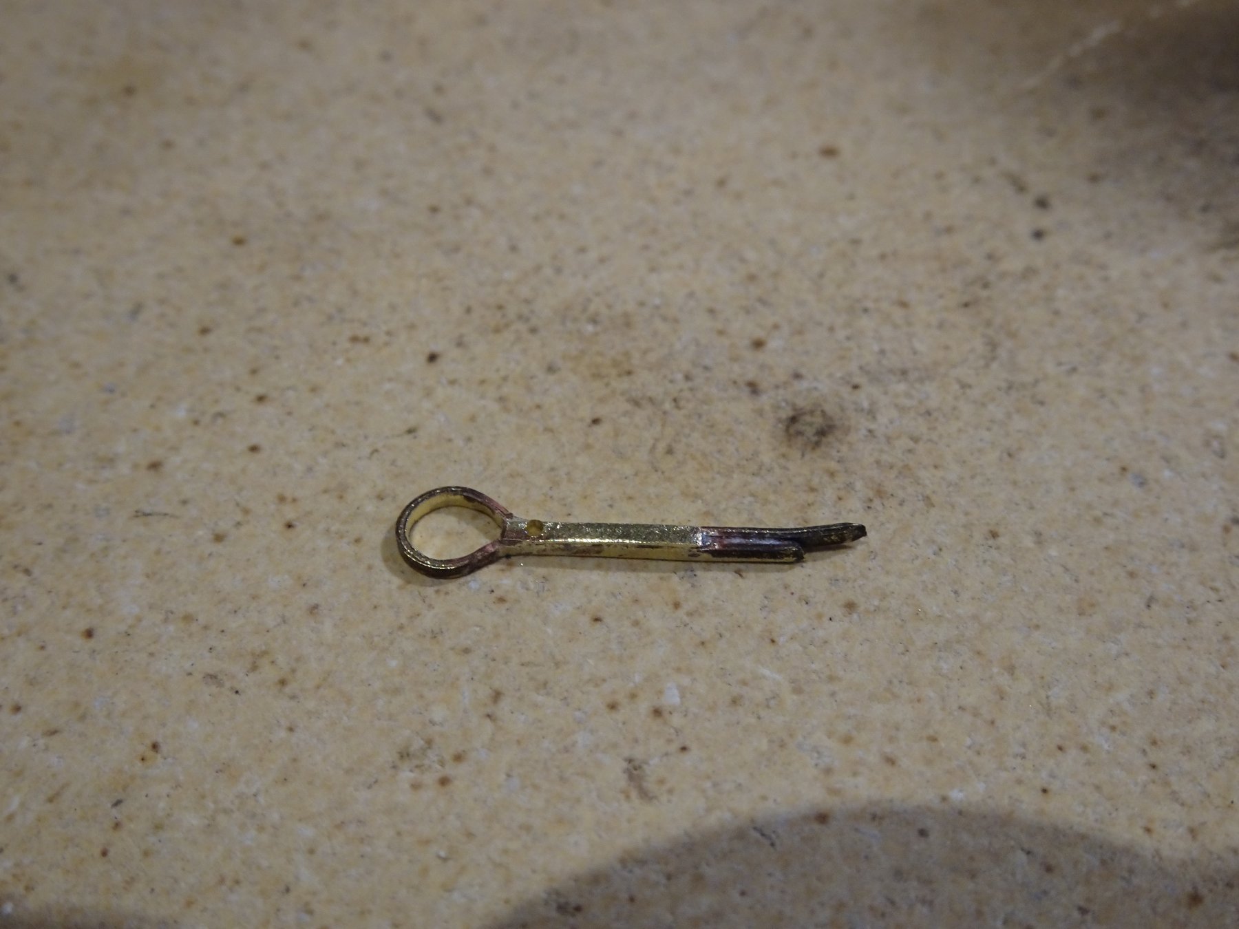
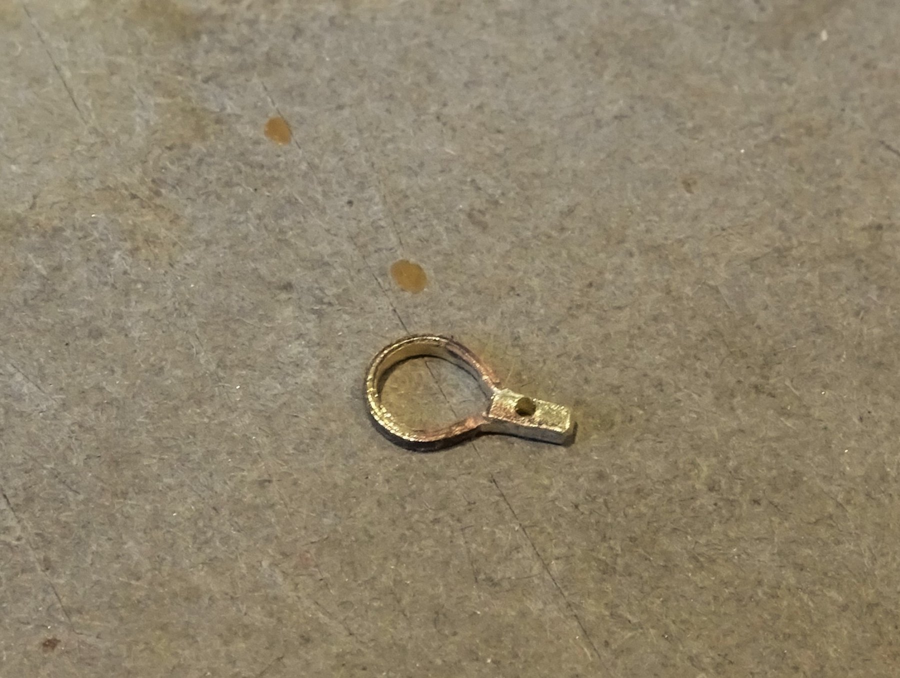
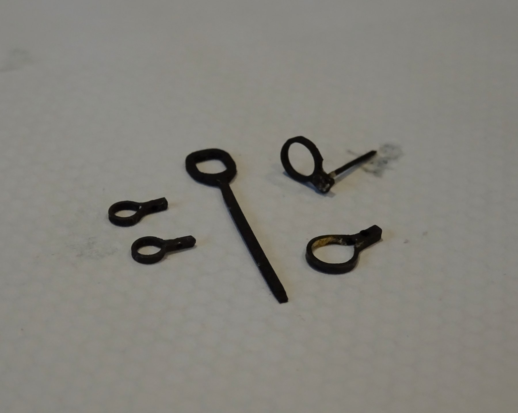
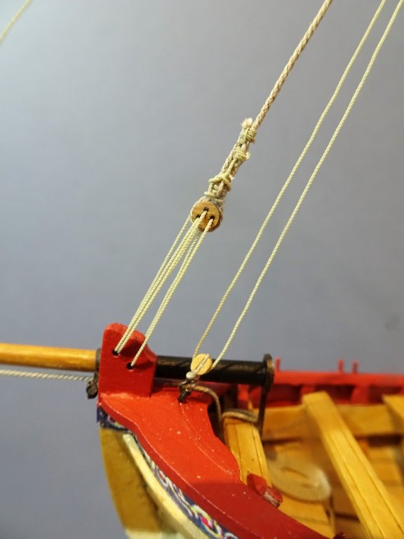
Thanks Martin, Limewood is really only of any use as first planking on a double planked hull, for any sort of finished wood items it is useless. Limewood dowel is also very suspect particularly in longer lengths, warping is a perennial problem. I do wish kit manufacturers would be more selective in the purposes for which it is provided. Bowsprit iron re-fit I realised that I had fitted the bowsprit ring at the stem at the wrong angle, pointing down rather than upwards as indicated on the Medway boat. The original was a bit tight anyway so I took the opportunity to re-make the item with a slightly longer stem. Again I used silver solder to fabricate the ring. 2530 Deadeyes and Chainplates. The supplied Deadeyes are of 3.86mm Ø which equates to a full scale of 7.29"Ø. By comparison the Topmast Deadeyes of a 14 gun sloop such as Pegasus are 7"Ø. According to Steel the deadeyes for larger boats such as carried by ships of 110 - 64 guns were of 5" Ø =2.64mm at scale; and for below that (ie smaller Longboats) thimbles were listed. As the Medway long boat model which is the basis of our model had deadeyes I have decided to go with Chuck's Syren 3mm versions. Chainplates The instruction indicate the use of 28 gauge wire to make these. For those who may not know, the higher the gauge number, the thinner the wire. 28 gauge is the thinnest of the kit supplied wire and equates on the AWG scale to 0.32mm Ø wire. In practice the kit wire is 0.40mm. I formed them as suggested in the instructions but I silver soldered along the join as a more secure method. I also formed the Chainplates for the Shrouds with two eyes so that the deadeyes can be hooked into the plates as with the contemporary 'Medway' Longboat. It took a bit of thinking about how to attach the hooks to the Deadeyes, and the best size of hooks to use to avoid an overscale look. I finally settled on Syren 3mm brass etched hooks. 28 gauge wire was passed thro' the hook eye and secured with a spot of silver solder; the wire was then passed around the deadeye, nipped and secured with a spot of ca. 2513(2) These were fiddly little things to make and the combined chainplate/ deadeye strop is certainly the easier option. Still some fettlin' to do to finish them off. Fairly straightforward to attach the chainplates to the hull, just need to ensure that the pins go into the frames to secure. 2527 2544 2555 2567 Just about ready for rigging now. B.E.
.thumb.JPG.5da96f90919e3af20695952de785830e.JPG)


- 91 replies
-
- 14
-
-
- 18th century longboat
- model shipways
- (and 1 more)
-
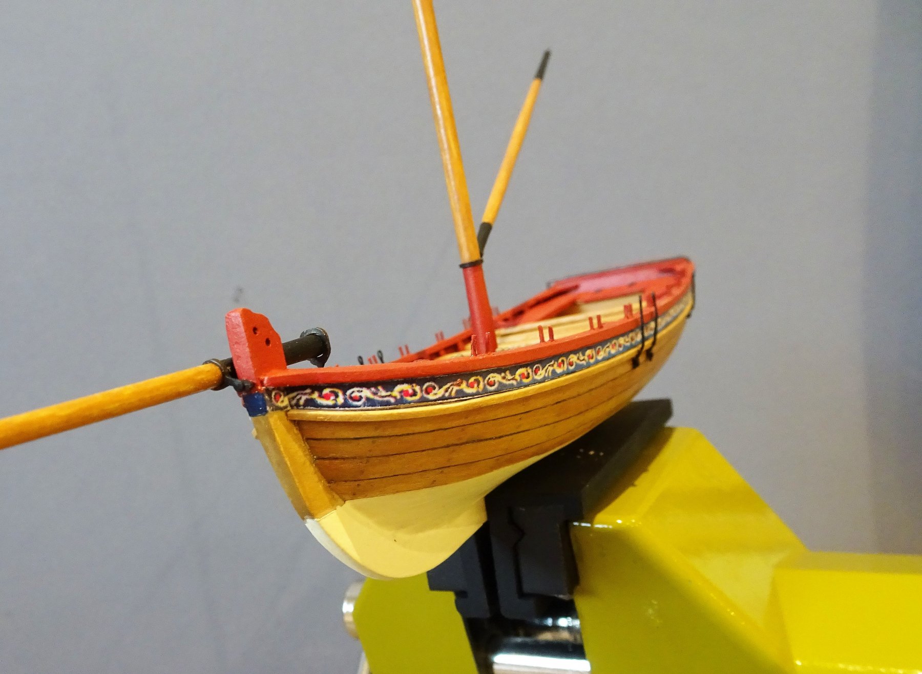
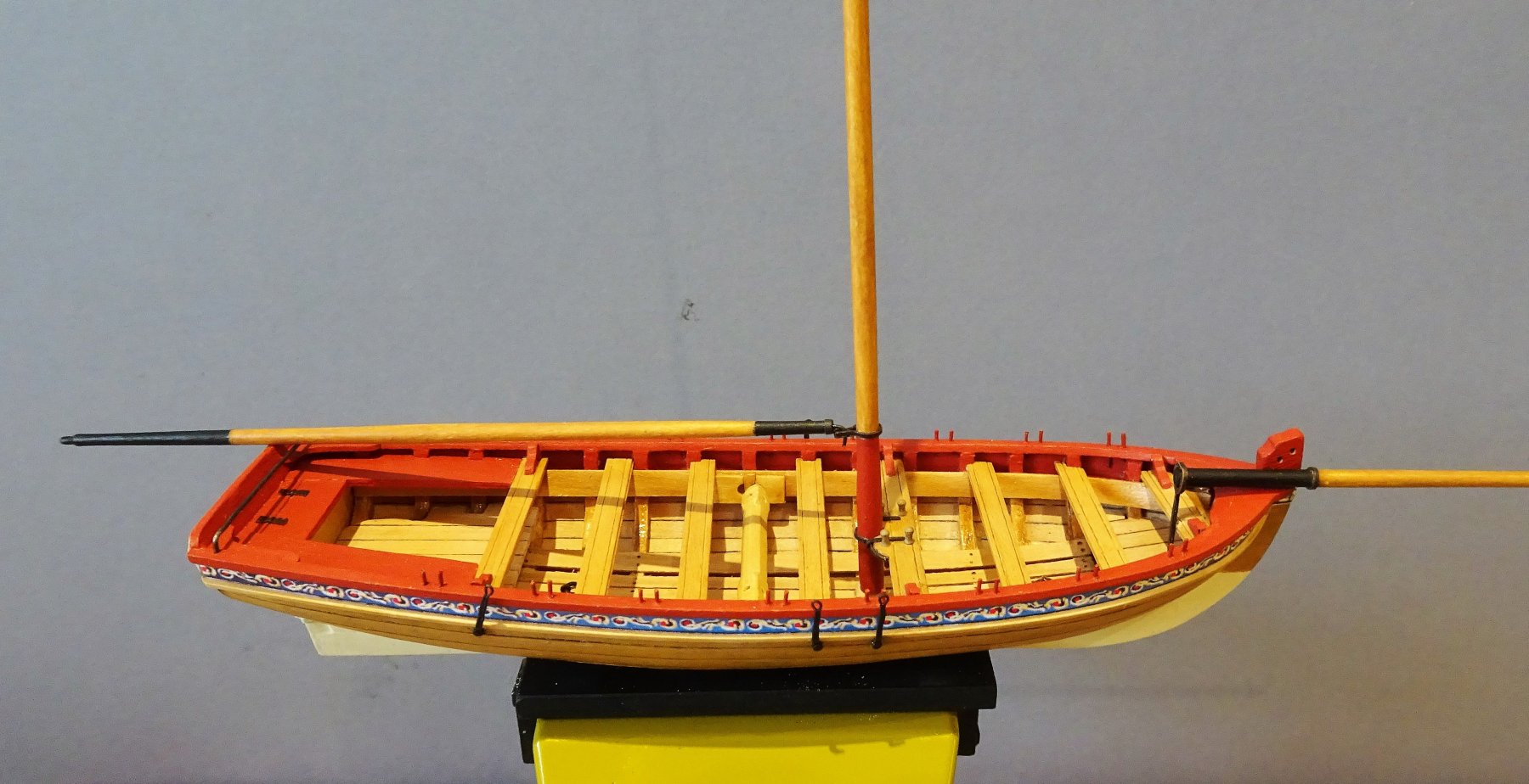
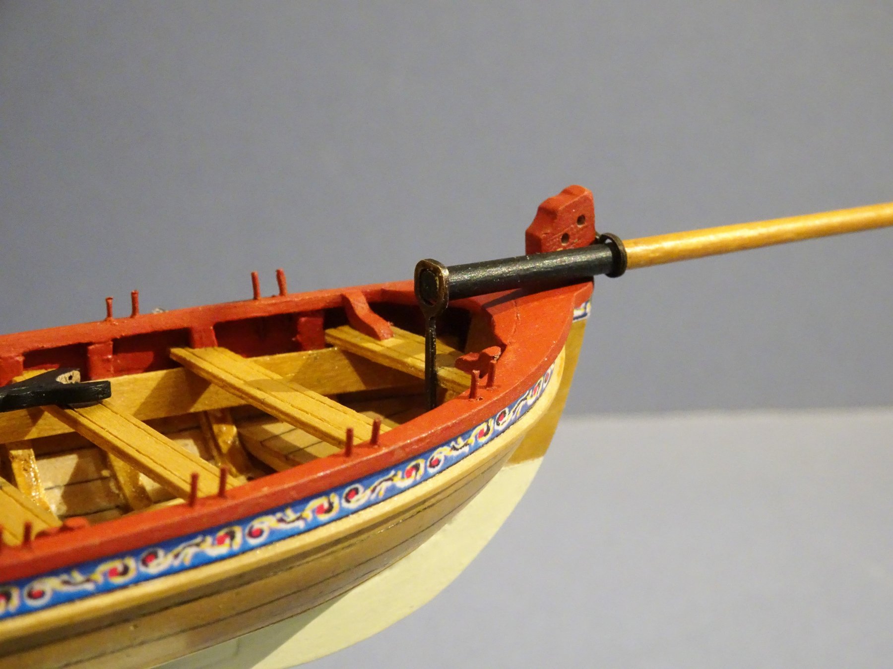
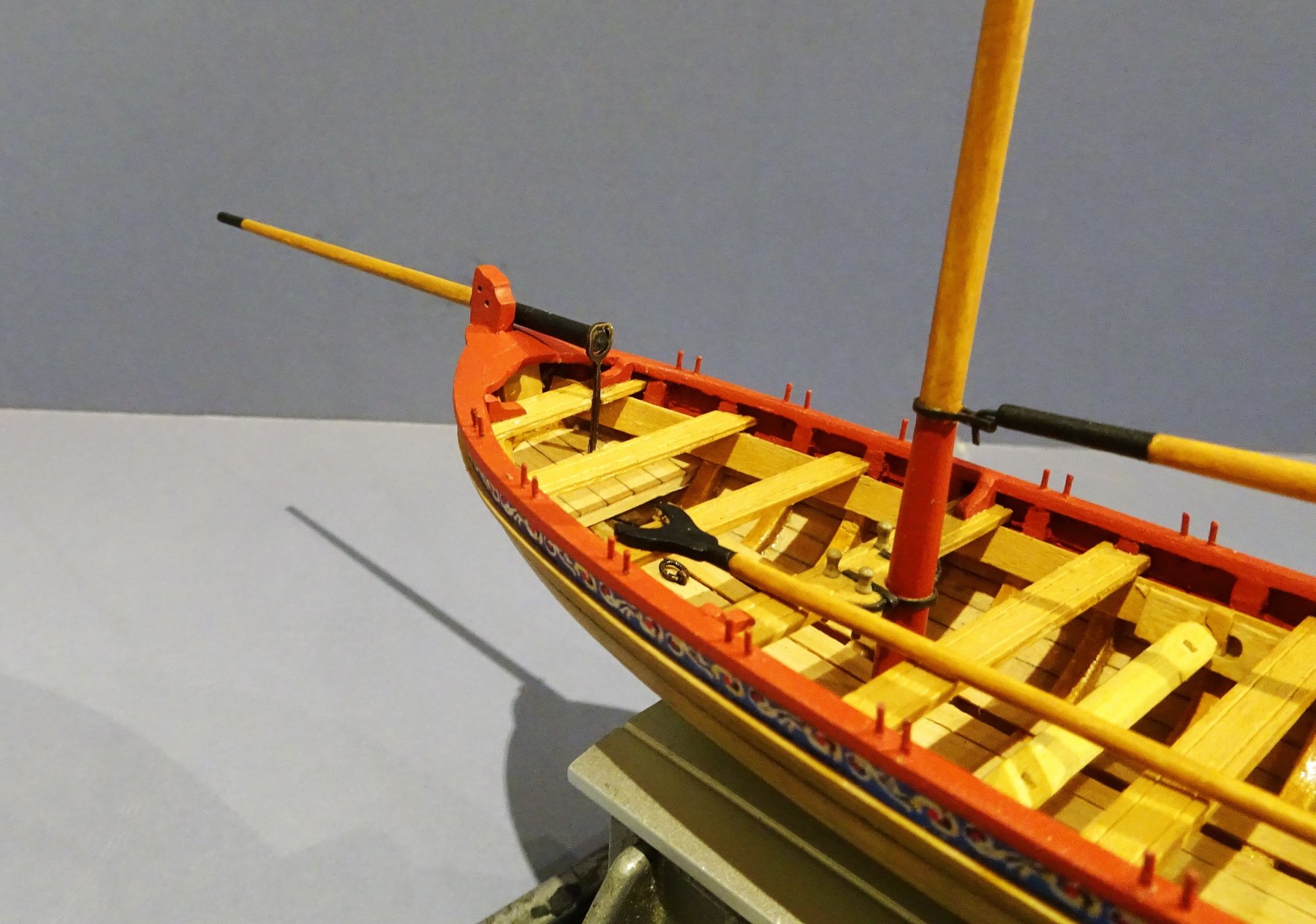
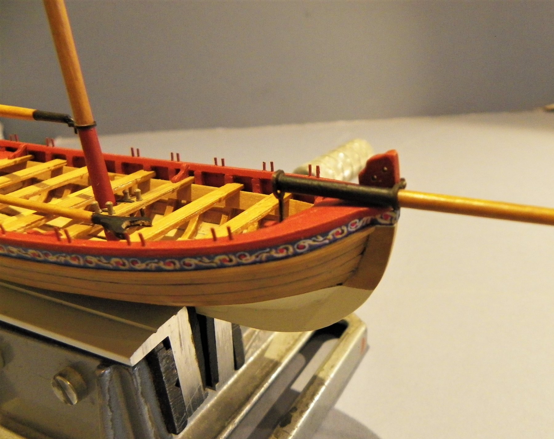
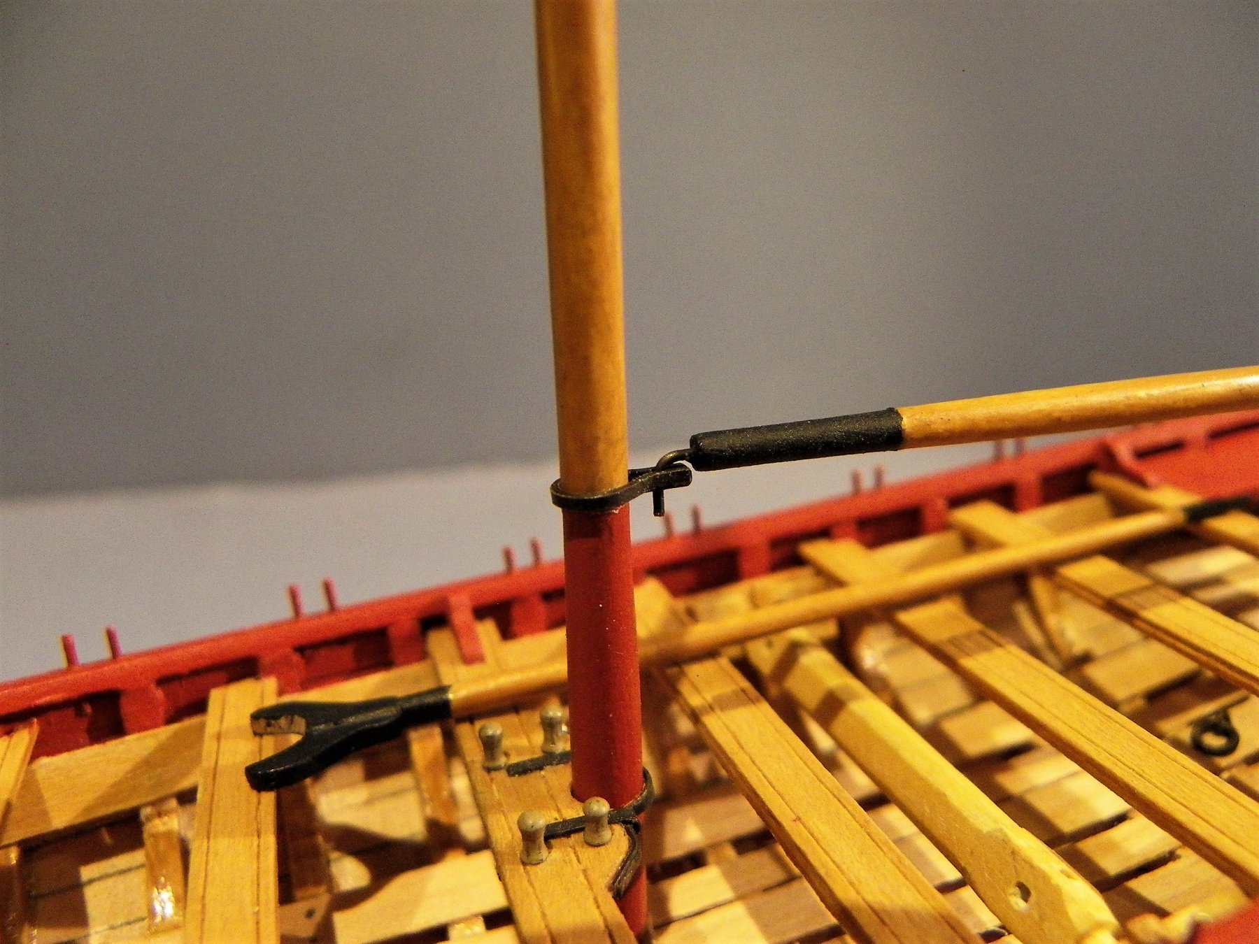
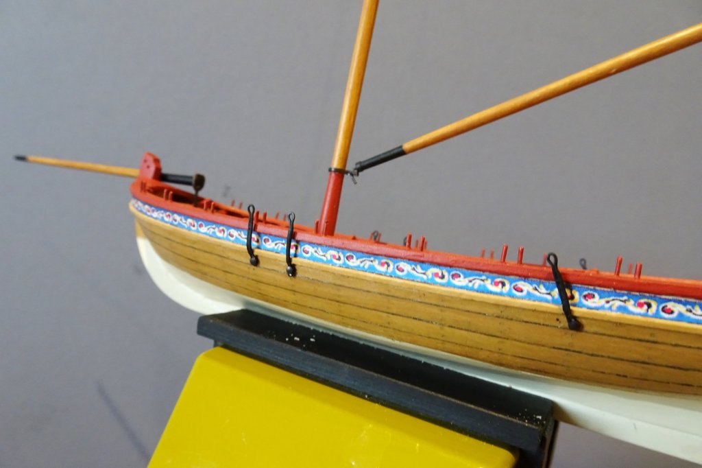
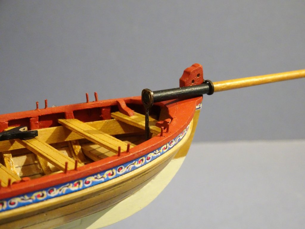
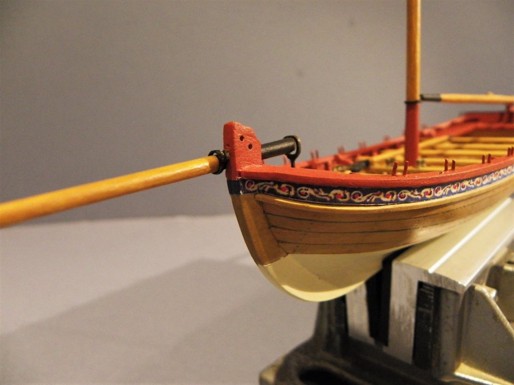
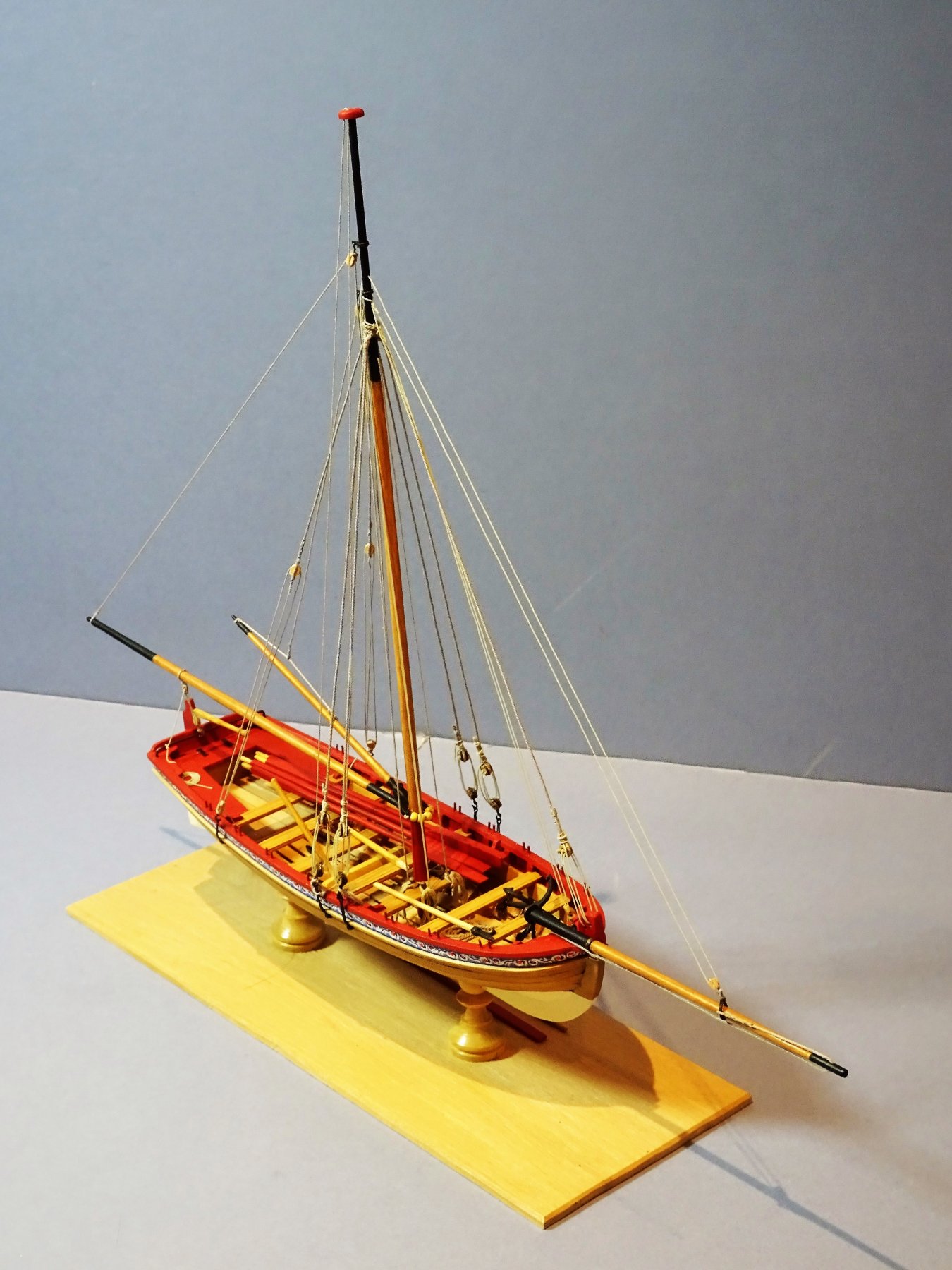
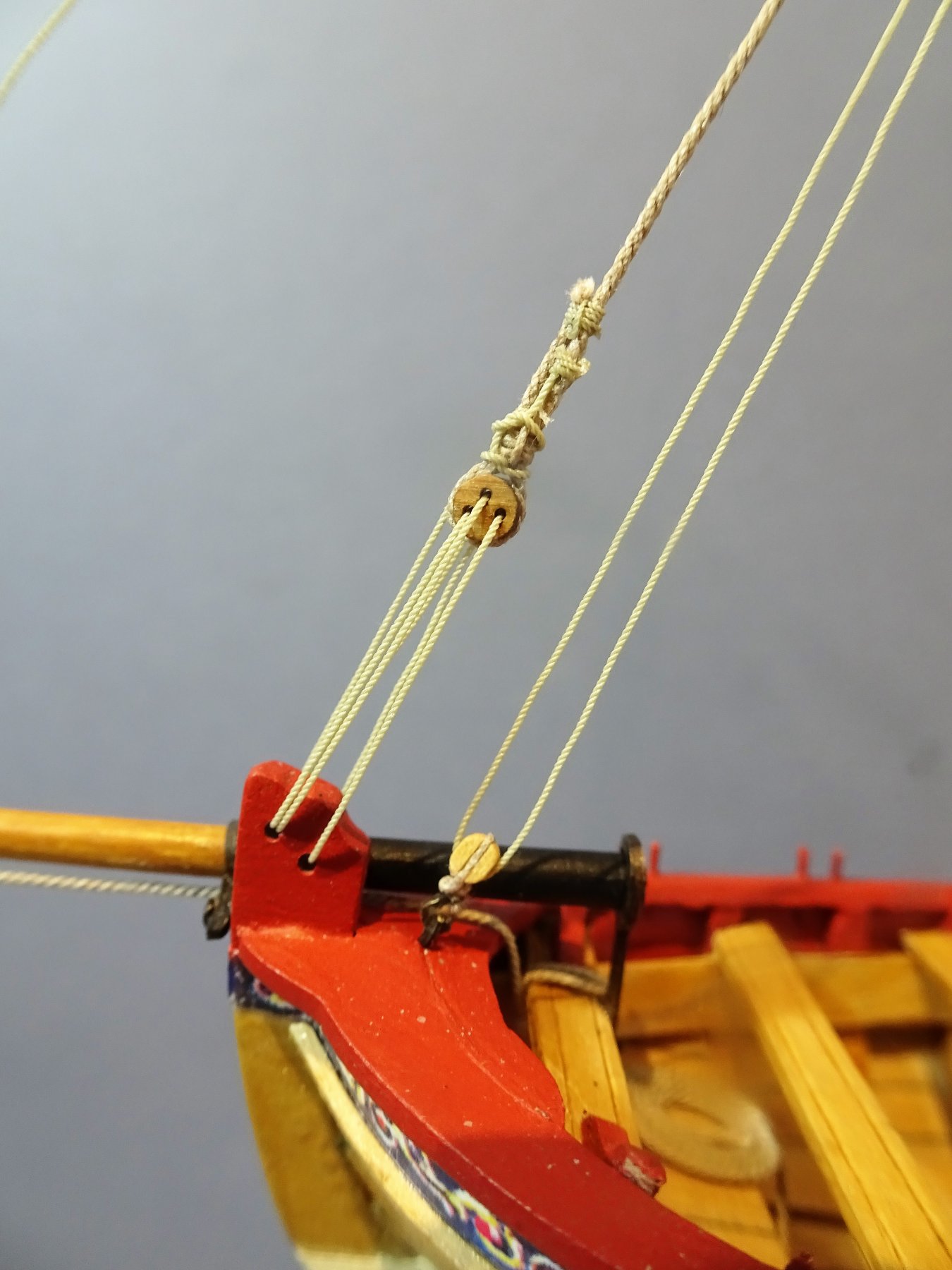
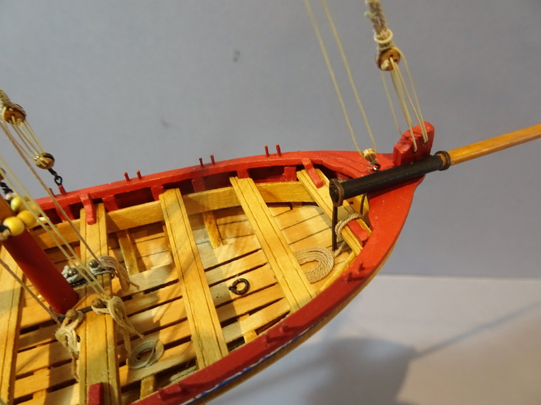
Fitting out With the spars completed the iron work for the Bowsprit is put into place. 4292 A little bit of fiddling to get the position right and give the Bowsprit a slight downward tilt. A shallow notch was cut into the first Thwart to assist a secure fix. 4274 4284 2377 4286 2418 2402 2413 2410 2371 Now back to the exterior to fabricate the deadeye chainplates. B.E.


- 91 replies
-
- 14
-
-
- 18th century longboat
- model shipways
- (and 1 more)
-
Thanks Martin, I think the dowel is Limewood, or Basswood as you American cousins call it. Very soft and unless it is sealed doesn't cover evenly, I really should have turned some Boxwood square stuff down or at least ordered some Ramin dowel. B,E,
- 91 replies
-
- 1
-
-
- 18th century longboat
- model shipways
- (and 1 more)
-
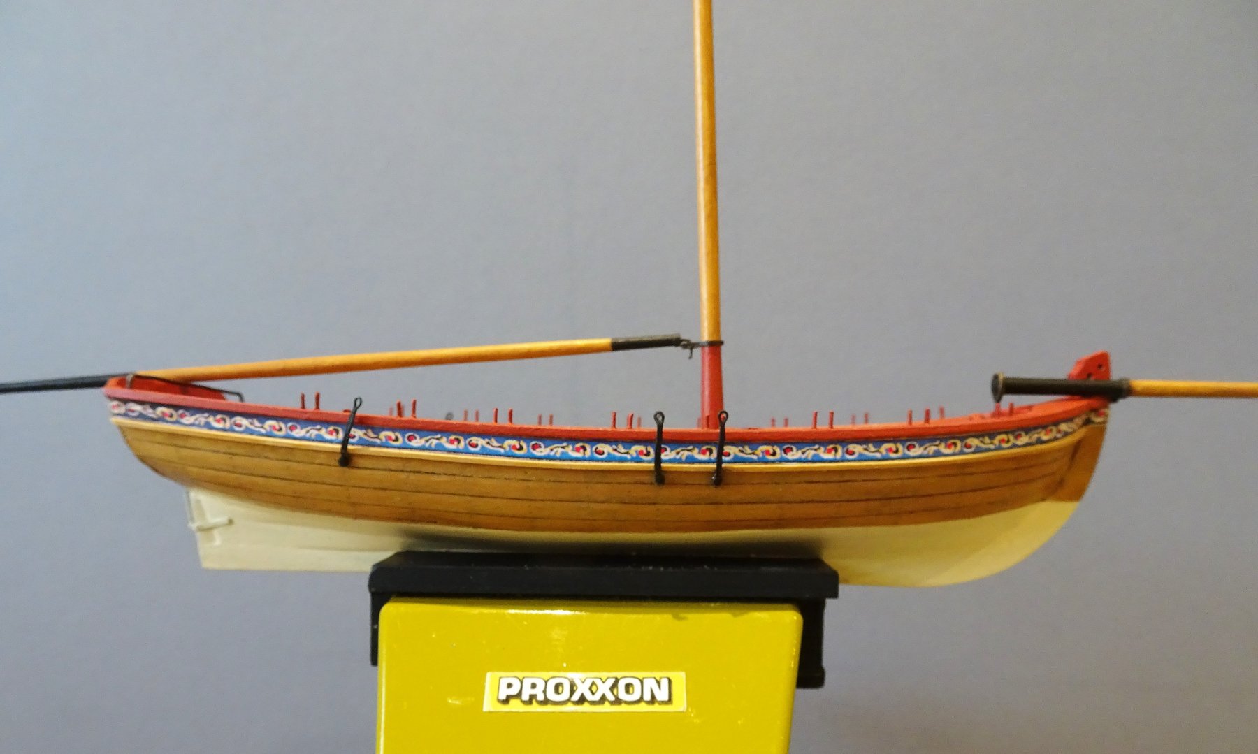
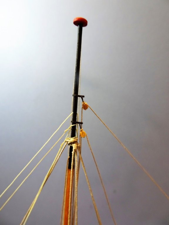
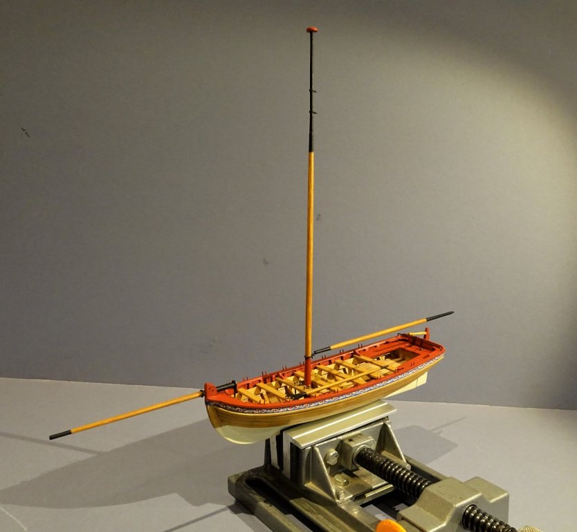
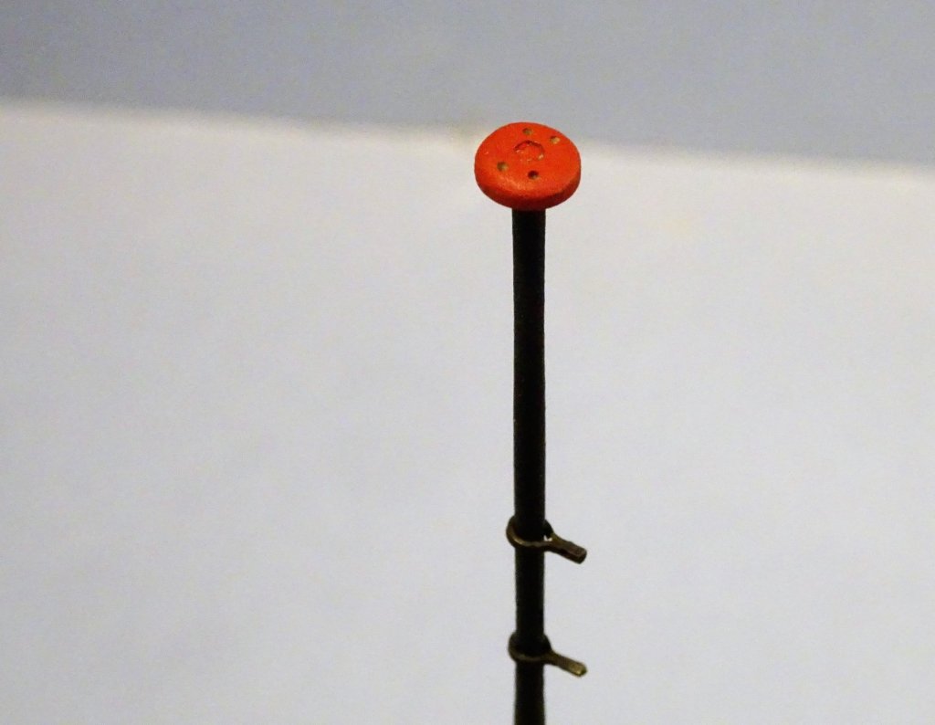
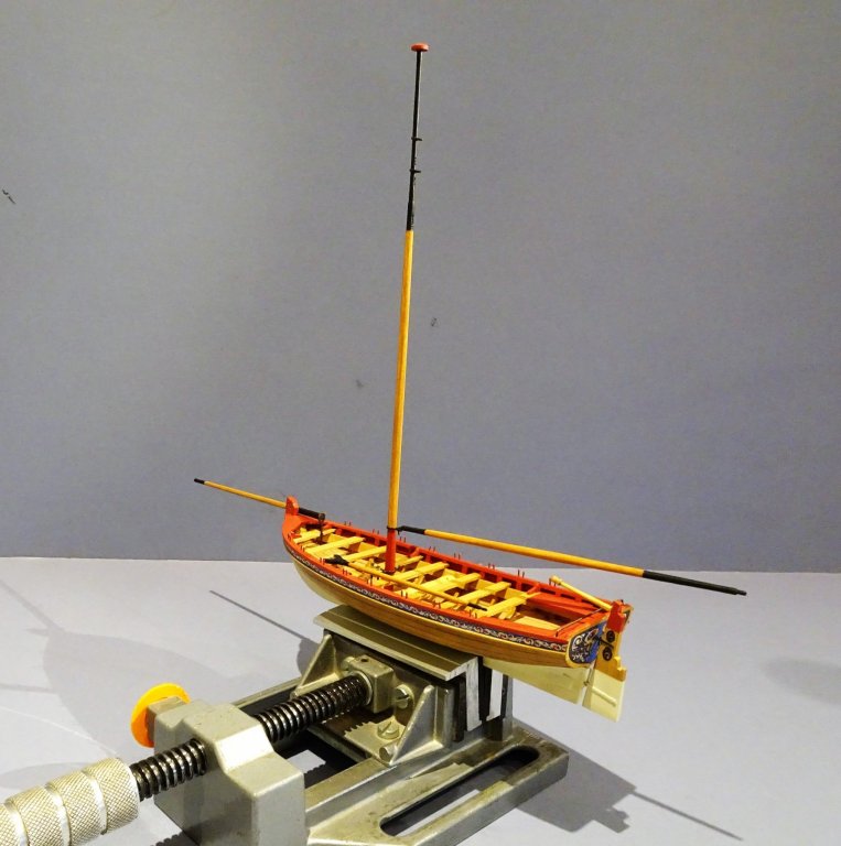
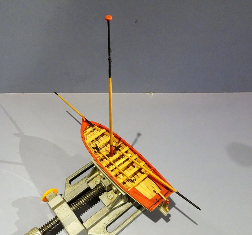
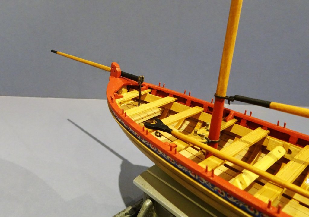
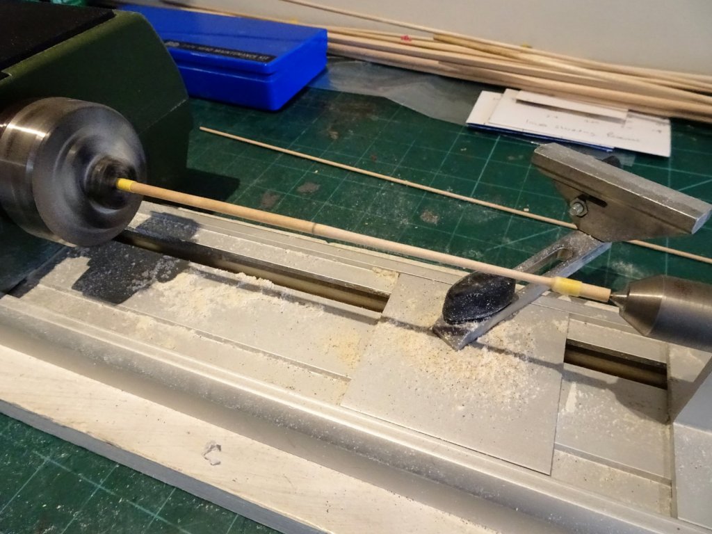
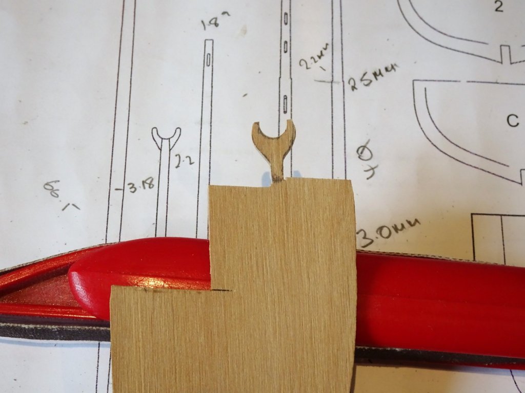
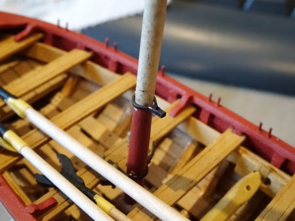
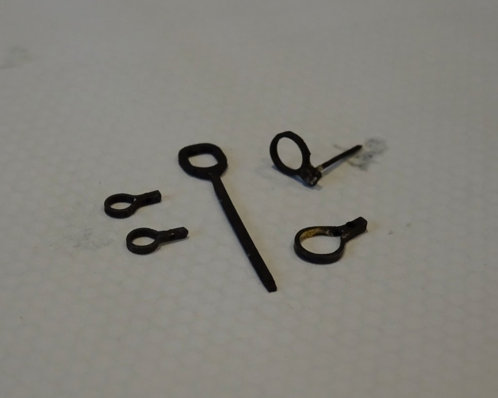
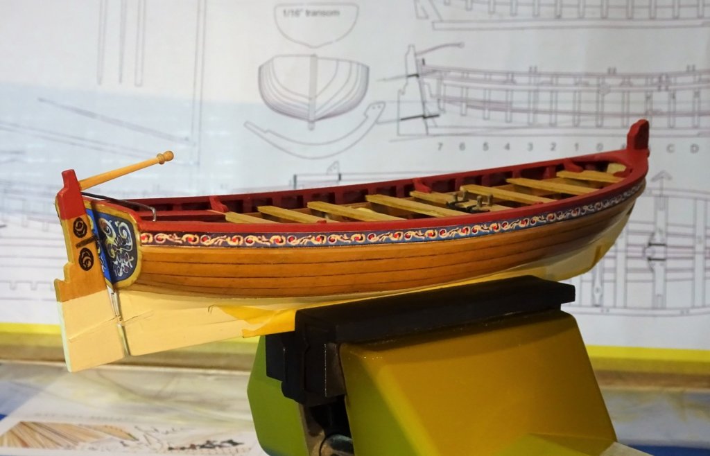
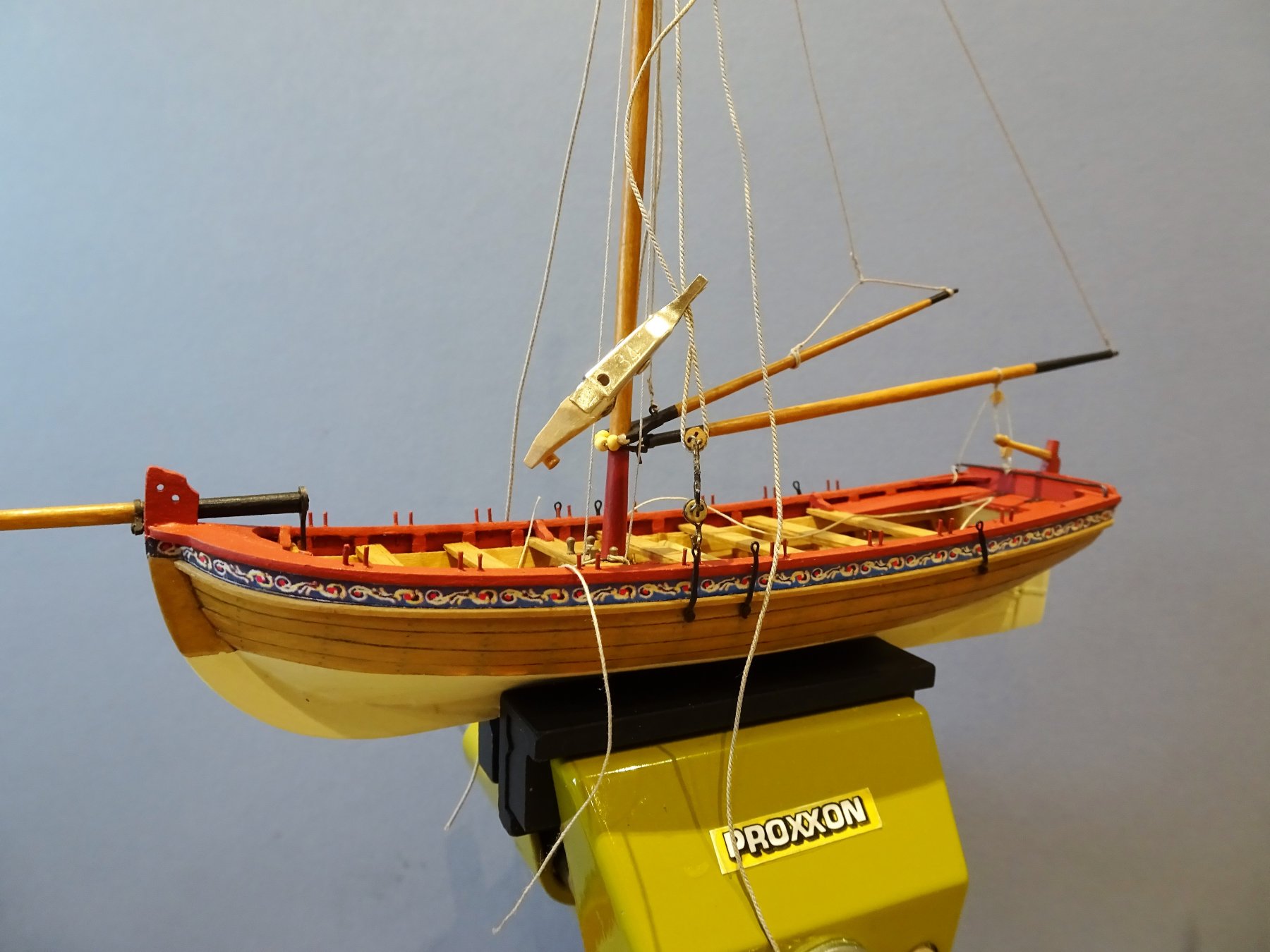
Many thanks to Al, Nils, Derek, and Mike for your interest and comments. Mast and spars. I have not gone into further research regarding the mast dimensions, I will fine tune it by eye. I divided the length from the thwart to the shoulder into quarters for the purpose of taper. From the plan 4mm at thwart, 3.6mm (1stQ) 3.5mm (2ndQ) 3.1mm (3rd Q) 2.5mm (Shoulder) From the shoulder to mast cap; 2.2mm 2mm at centre, 1.8mm at truck. A card gauge is used to monitor progress at the Quarters. 2236 The tapering was done on the Proxxon wood lathe. Making of the Bowsprit, Gaff and Boom are fairly straightforward. 2237 The Gaff jaws were fashioned from some Boxwood sheet, and it should be noted that the Boom is tapered each end from the centre where it thickens slightly. Boom Iron Always seeking the easy route I initially followed the kit instruction for making this; c.a. the ends and twist the extension to the horizontal before drilling the hole for the Boom Gooseneck. 2238 This didn't work for me the c.a. failed to hold following the twist, so I reverted to silver soldering which achieved the objective. 2241 2246 2250 Trial fitting of the Boom iron. The mast dowel takes some distress during the iron fitting process. Would have been better to use Boxwood for the spars I think. 2254 The completed iron set. Mast colouring. The problem with using the provided dowel is that getting a good finish using just varnish is tricky. Patchiness, uneven coverage, and strange over-scale grain patterns show thro'. I found that sealing the dowel with matt varnish was necessary to seal the surface before applying my tinted varnish mix. Several coats later with light in-between fine paper rub downs and I get the look I'm after. So here's the completed masting set. 4297 The varnished parts were of a satin finish, and to complete they were coated with matt varnish. B.E.

- 91 replies
-
- 14
-
-
- 18th century longboat
- model shipways
- (and 1 more)
-
Thank you Michael and Don. @ Don - I just sourced the inkjet film on Amazon and picked a five sheet A4 sized film. I only used it for the rudder decoration but it worked out just fine. B.E.
- 91 replies
-
- 2
-
-
- 18th century longboat
- model shipways
- (and 1 more)
-
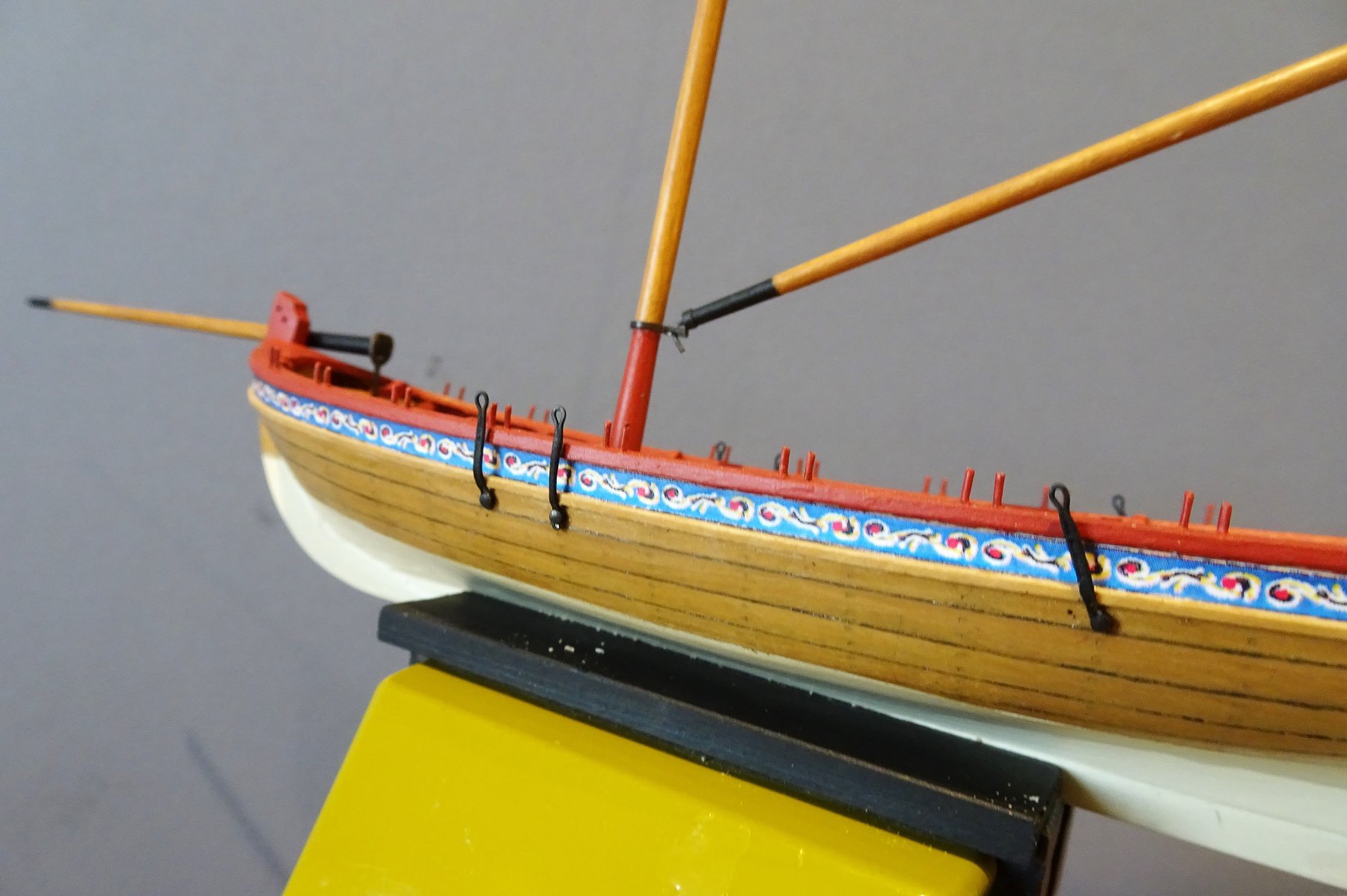
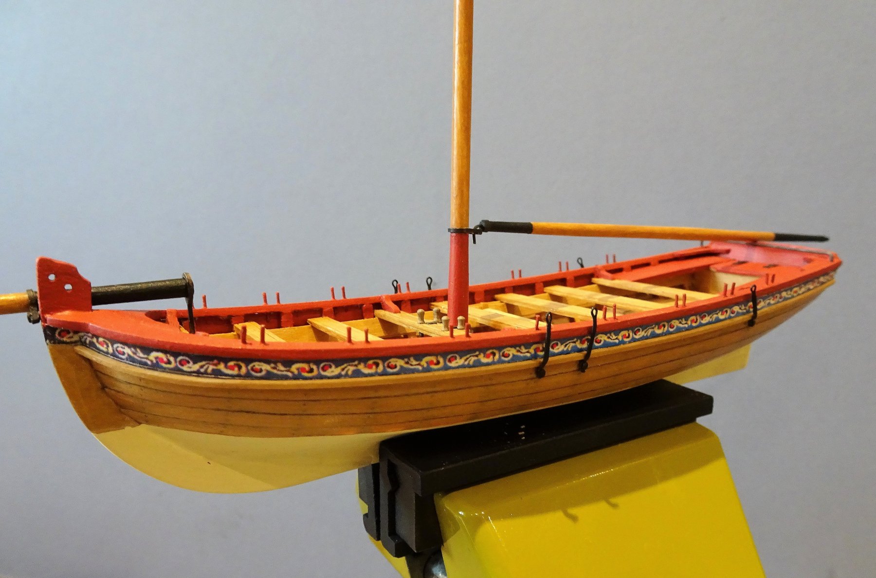
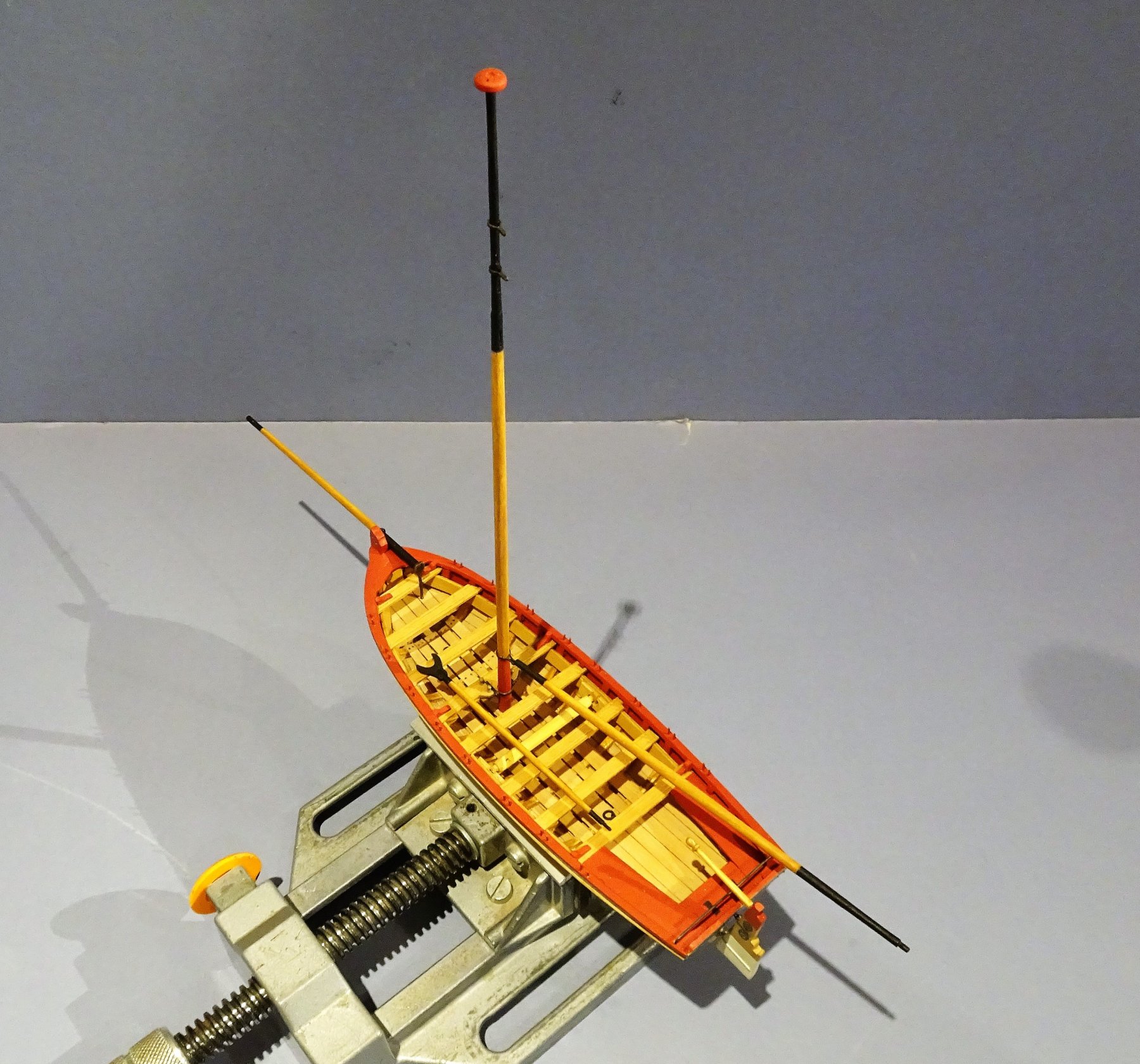
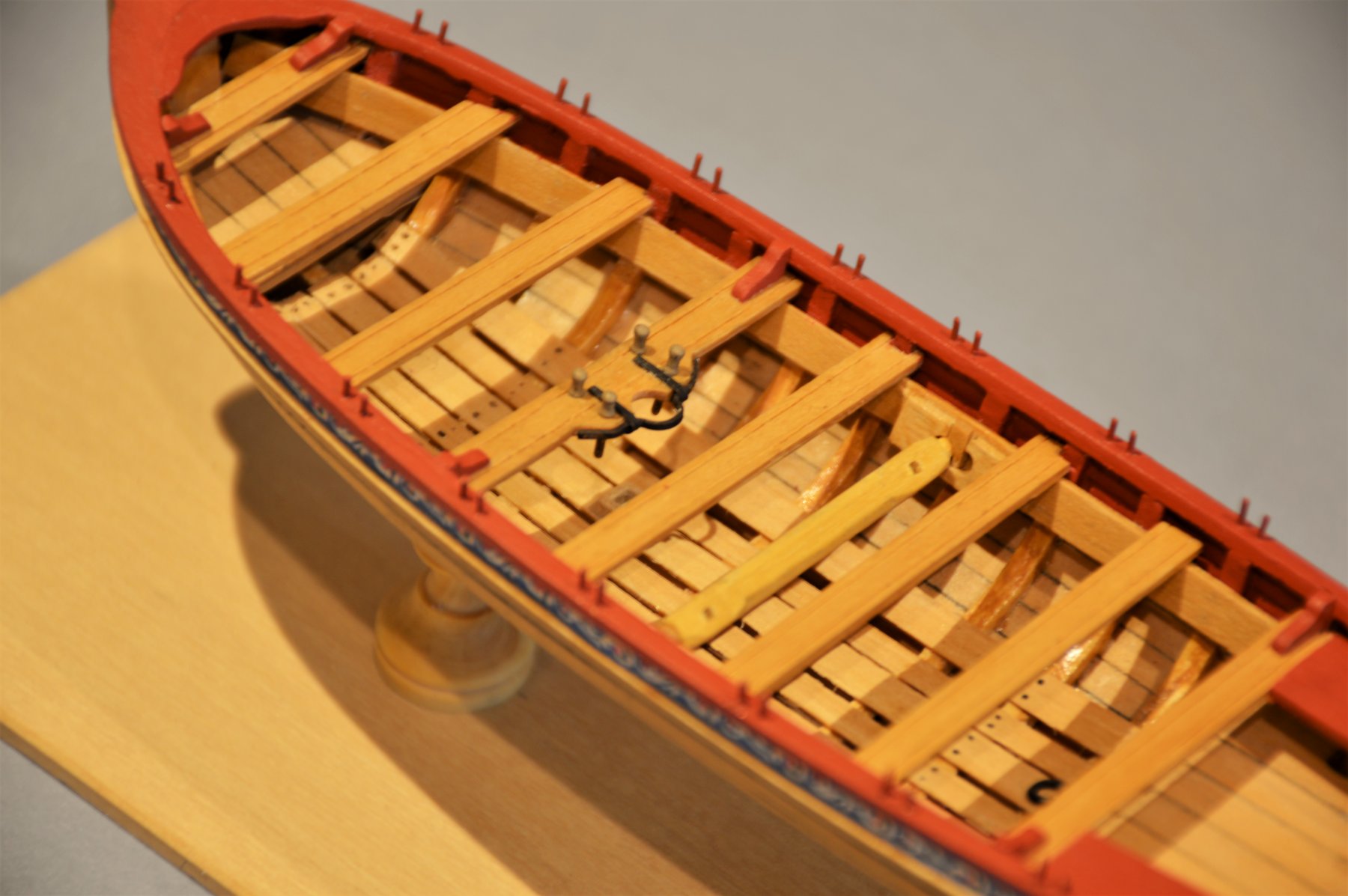
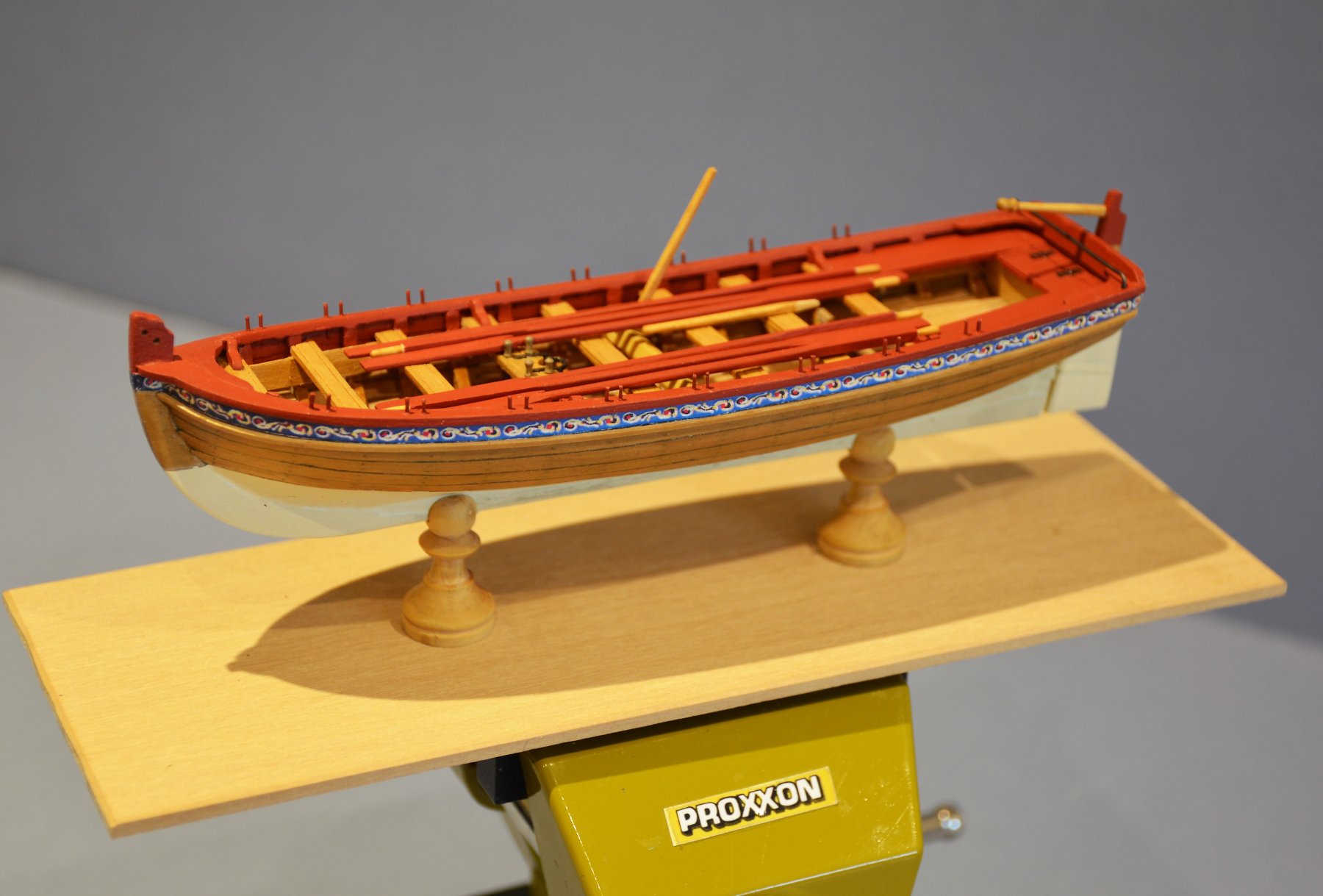
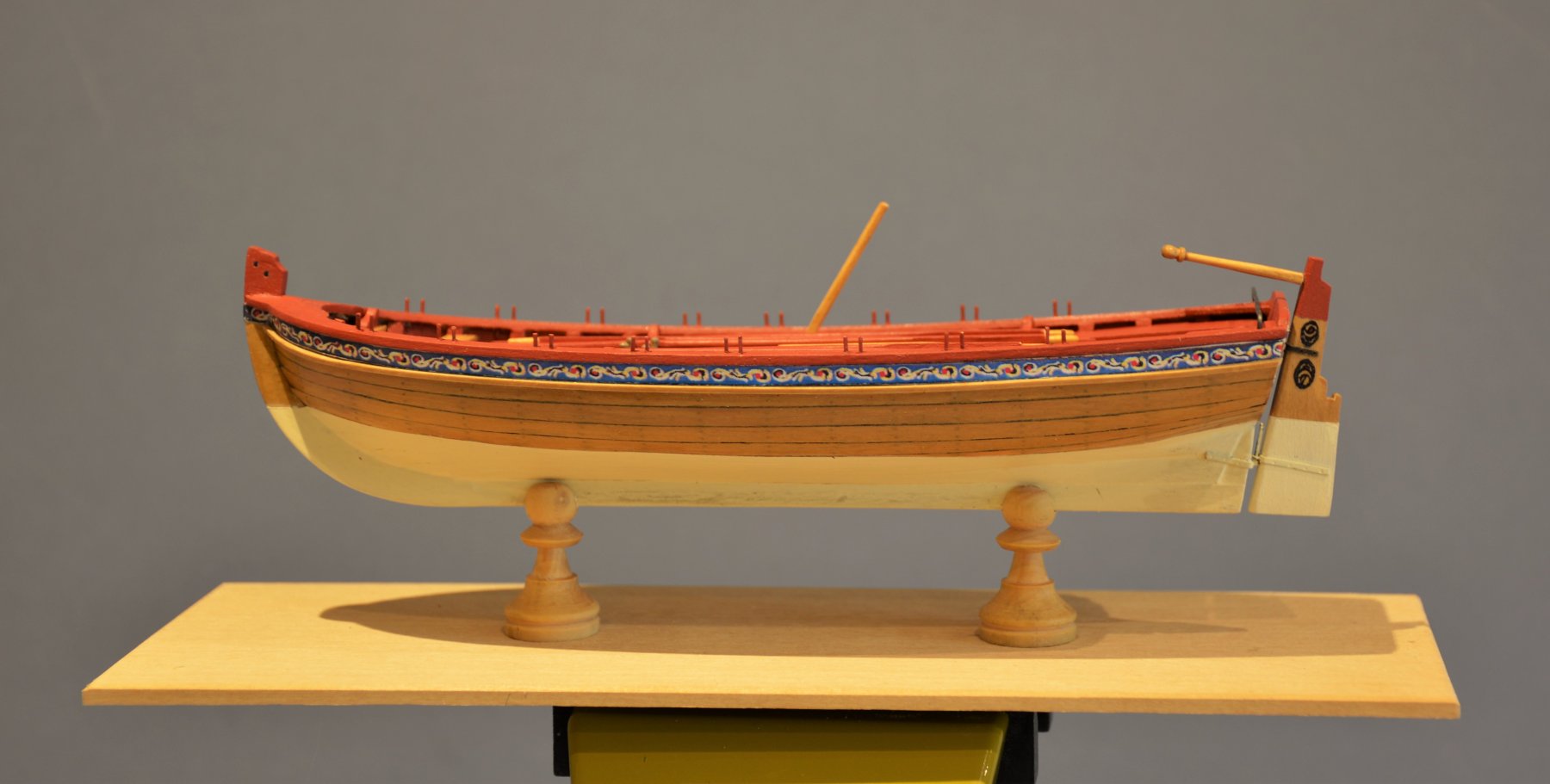
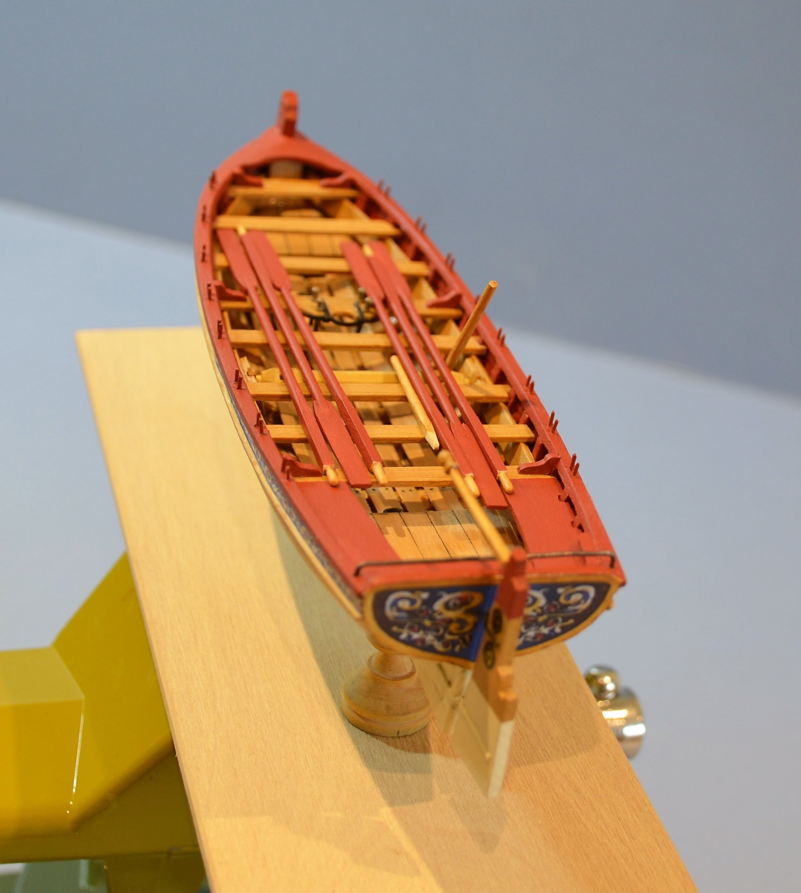
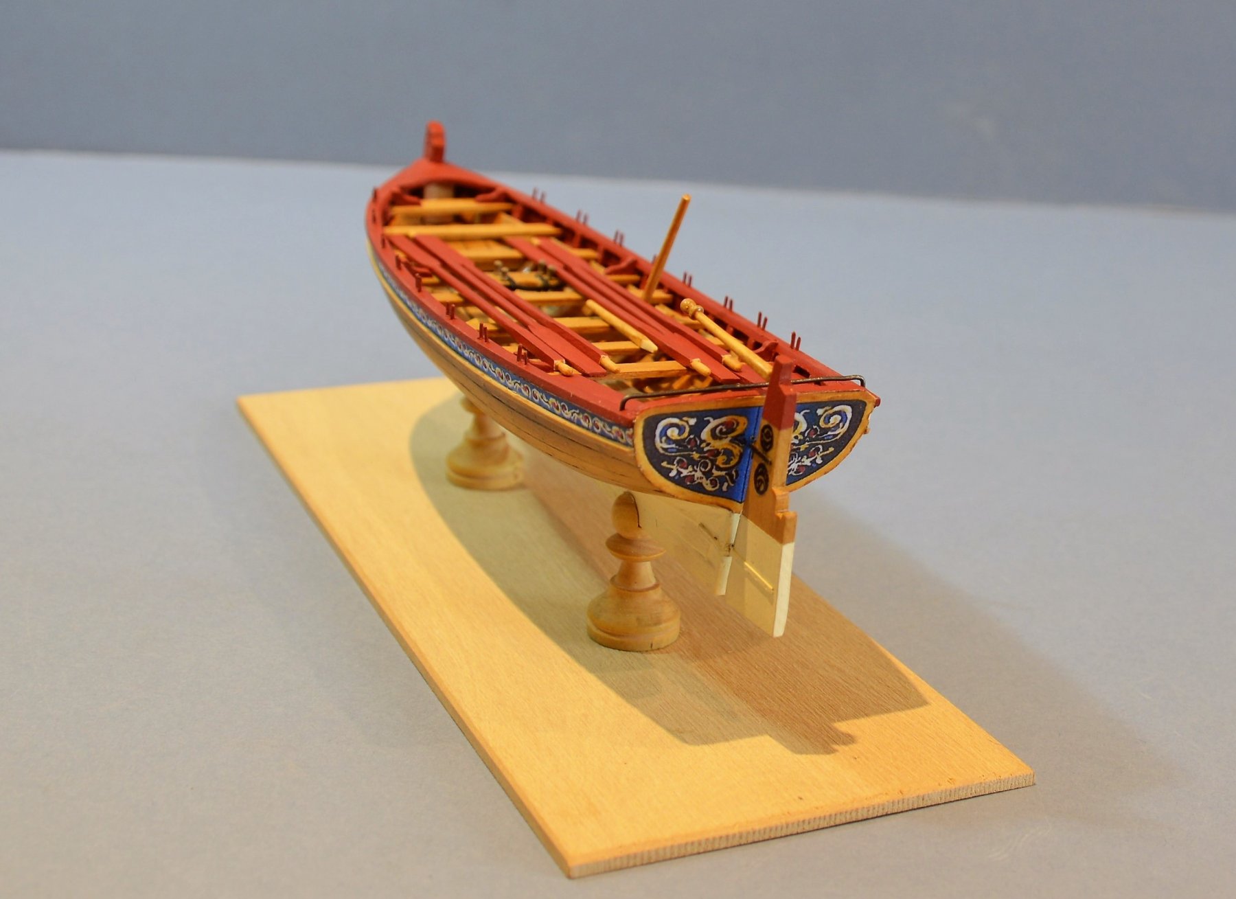
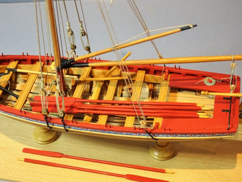
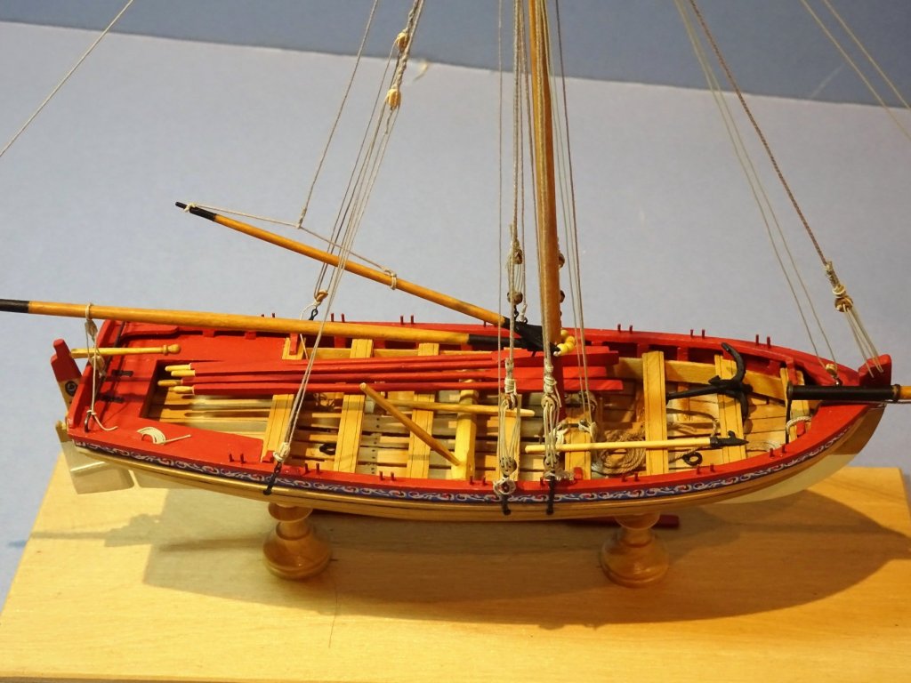
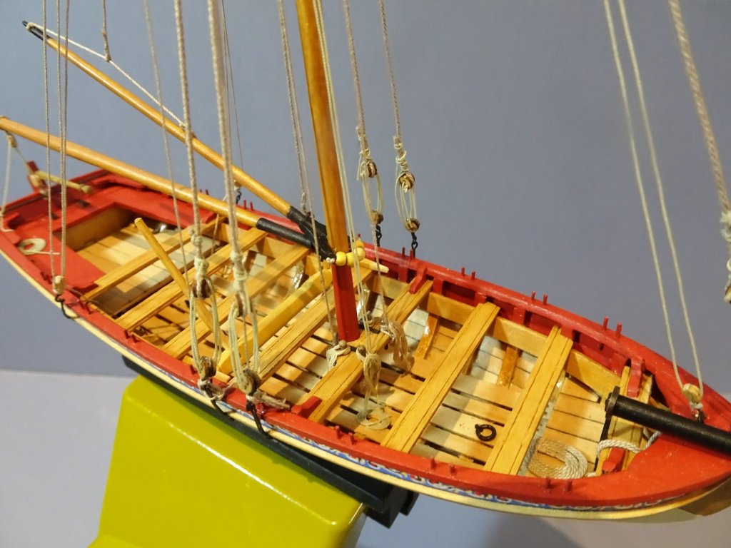
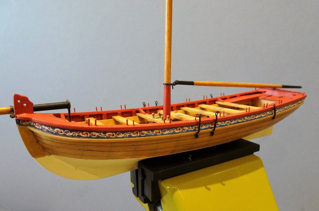
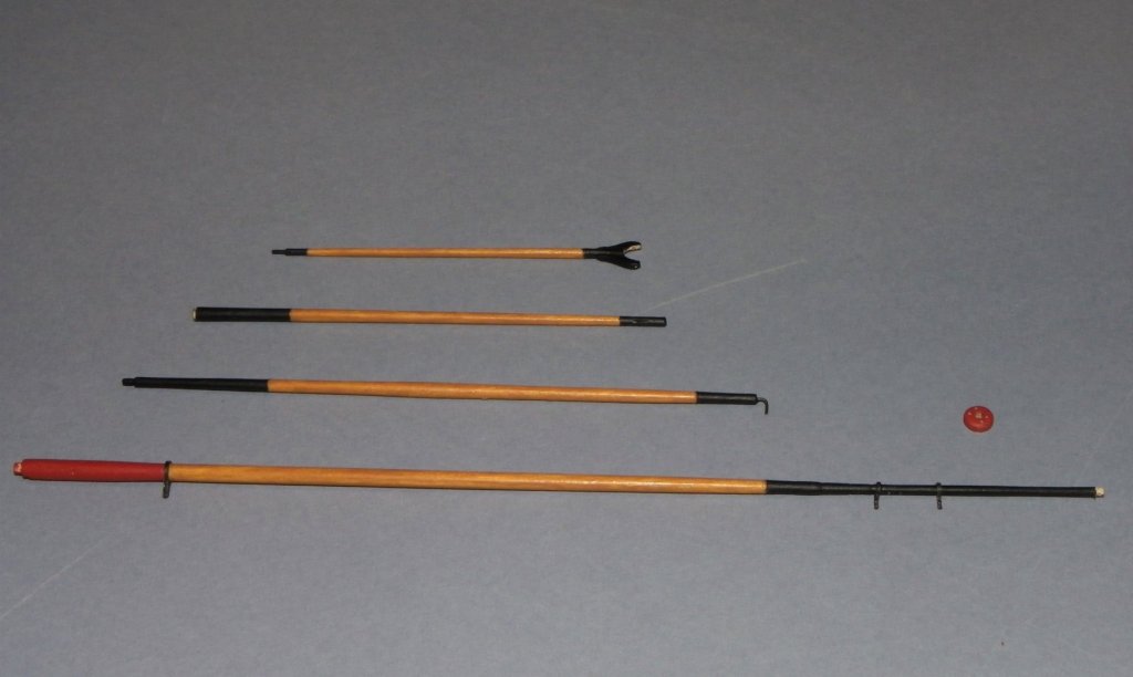
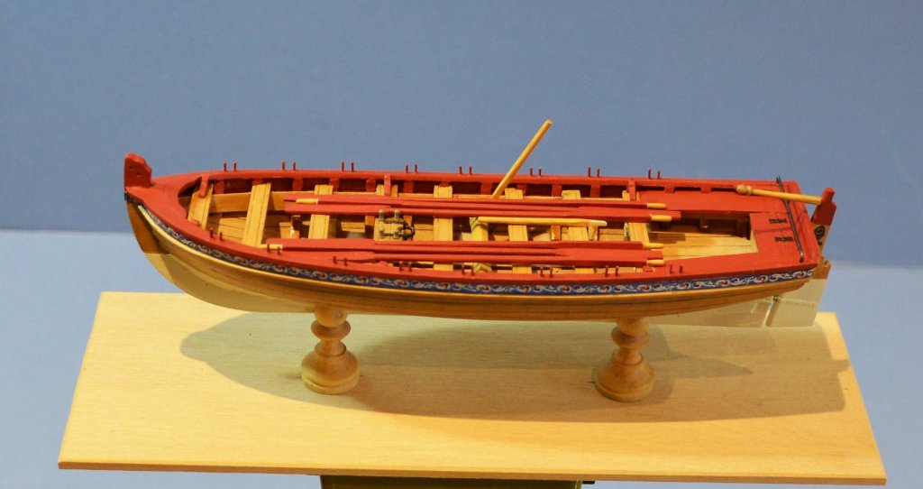
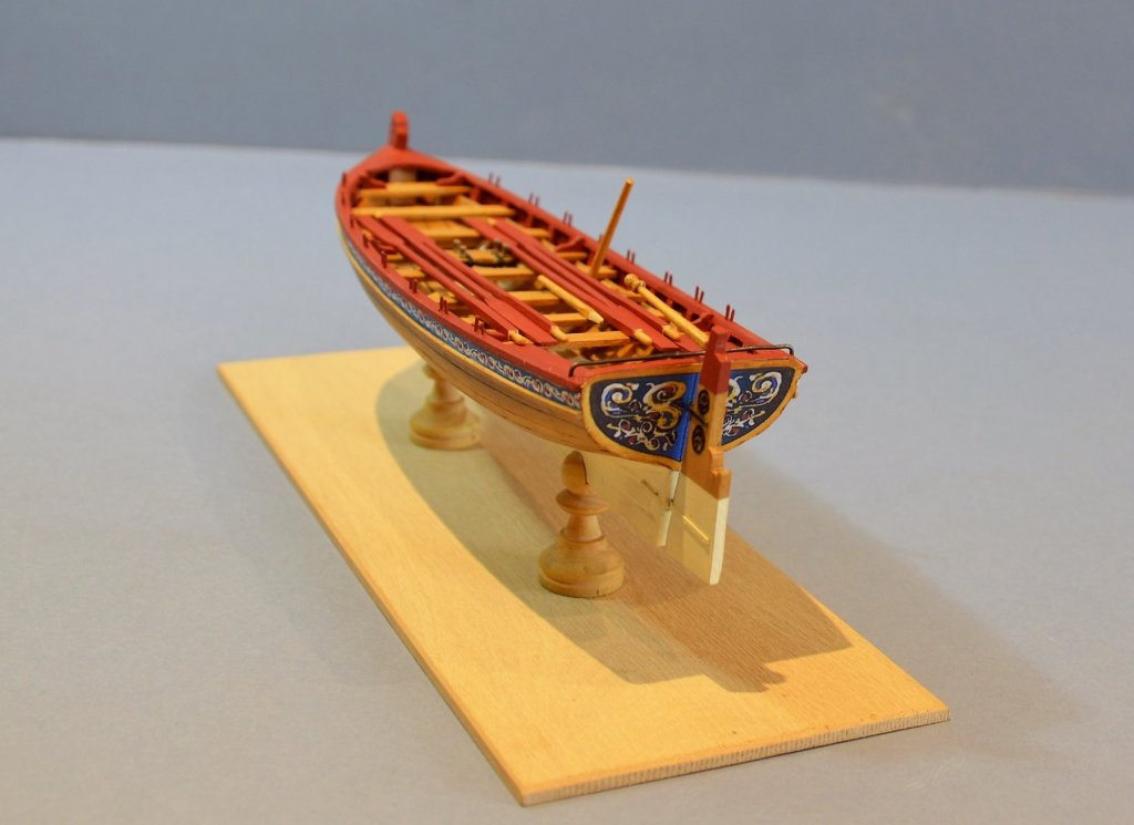
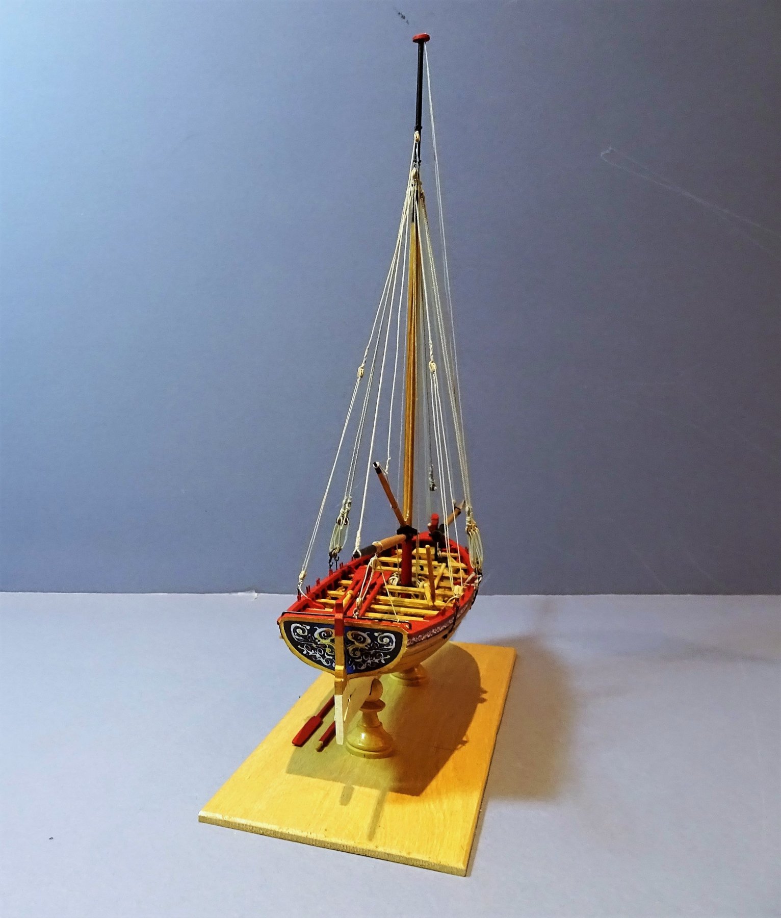
An inboard fitting and fiddlin' session. To finish off the rudder I added the decorative panels. I had been waiting to get some Clear Self Adhesive Inkjet Sticker Label Film to print these out. 2084 2085 At only 70 microns thick it shows no edge profile and gives a good impression of a painted on design. 0429 The lifting ring bolts are put into place and the mast support 'iron work' fabricated. 0453 I have now made a set of six oars and the Windlass Bars, and this basically completes the boat as fitted for rowing. Regarding the Windlass Bars there doesn't seem to be any reference to the scale length of these items either on the plan or in the instruction book. Had difficulty finding any reference to bar length but I guess around five feet to provide satisfactory leverage. Finally the Thole pins were added; I deviated from the kit arrangement by setting the boat up for double banked rowing which I think was the norm for Long-boats. 0434 0456 0475 02231 02228 0439 This has only been a seven week build to date altho' it feels much longer. I now move onto the masting and rigging of this fine, if not at times troublesome little kit. B.E.


- 91 replies
-
- 15
-
-
- 18th century longboat
- model shipways
- (and 1 more)
-
Love this model Don, and your work on it. Those sails look excellent to me. B.E.
- 653 replies
-
- 4
-
-
- trabakul
- marisstella
- (and 1 more)
-
Beautiful work on the Headworks Bob, crisp and clean, love it. B.E.
- 682 replies
-
- 5
-
-
- halifax
- lumberyard
- (and 1 more)
.JPG.d875b0619f8c78c23738b2ce0b8d3e65.JPG)
.JPG.4cf5dd91d2c377b57ce7560dc1f83c73.JPG)


.JPG.b8165a98f1ff295030020f5f6f02d6f6.JPG)