

Chuck Seiler
-
Posts
1,878 -
Joined
-
Last visited
Content Type
Profiles
Forums
Gallery
Events
Everything posted by Chuck Seiler
-
 I have the Ultimation hand disk sander as well. In general, I don't like it as much as my Byrnes disk sander, but it is far more portable...and quite useful. I find, however, it must be clamped to the workbench or it slides all over the place.
 -
I remember seeing a model in a museum in the LA area where the 'pot metal' parts had all disintegrated into piles of grayish-white dust. I was told they were the lead fitting used a loooong time ago. I think the newer mystery metals such as Britannia don't do that (at least in my lifetime).
-
Those rope seizings look really good.
-
Siggi, Amazing work! What are you using for nails/rivets?
-
I have the V2 version and have gotten as far as making the frames (while I work on another model). I have thought about using copper wire, with the end treated with a cupping burr. Once the nails/rivets are in place, they can be darkened using Liver of Sulpher...at least that is my theory. I am told LoS does not stain the wood. Alot of work, though.
-
Is this going to be double planked ( second layer of thin planking over the first), a single planked painted or single planked stained?
-
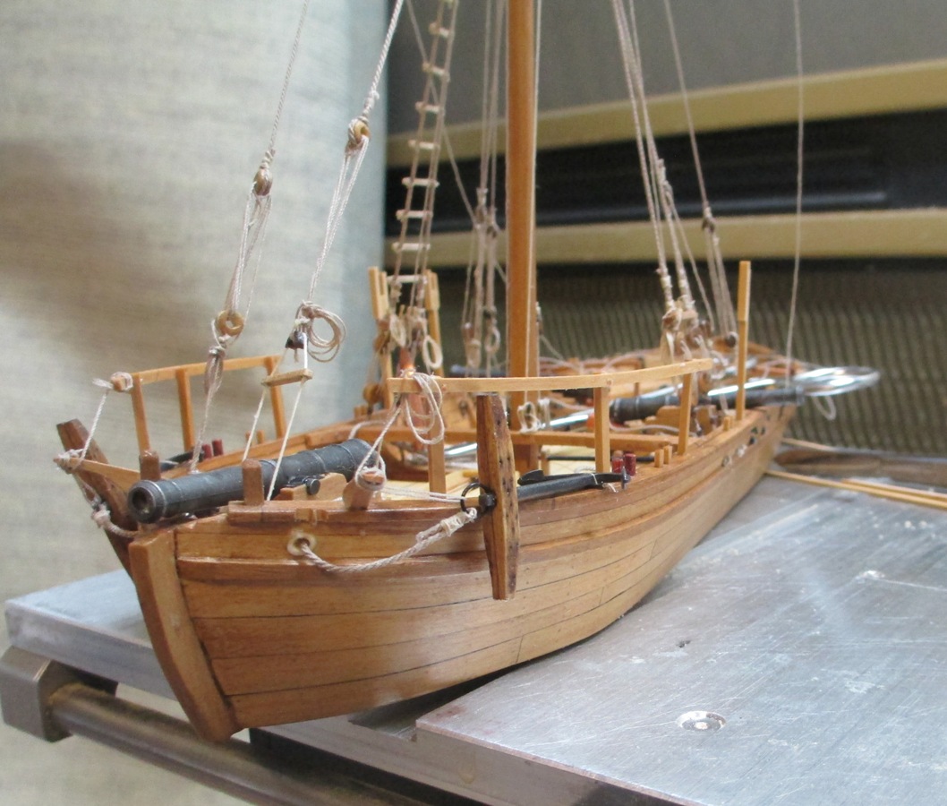
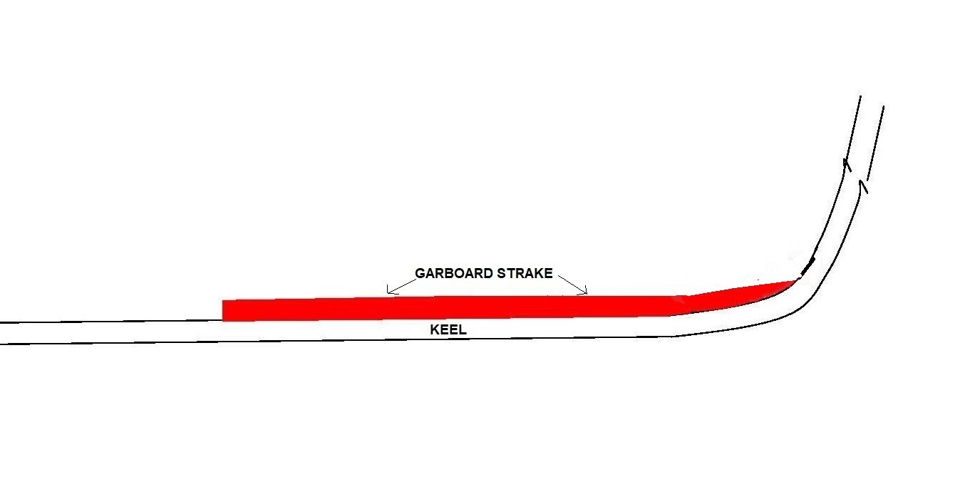
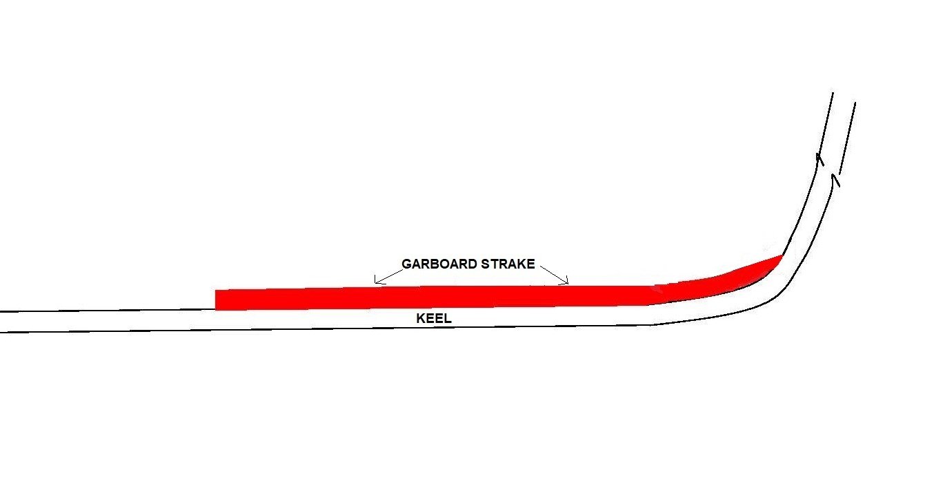
You are correct. That was a poor representation of what I was trying to get at. The updated drawing is probably better. The key is dry fitting a plank or cardboard template so that it snugs into the curve of the stem. As you say, the upper edge should be straight. It will be a natural fit.
-
I had that problem as well. I read alot about it and followed many build logs. The light finally came on when I took what I had learned and started experimenting. By taking a test plank and sanding the bow end as I go, I test fit the plank. At one point, the plank fit snug with little or no problem This was normally right at the curve of the keel up to the stem. Working it out just from plans never worked. Test plank or cardboard template in conjunction with the model ended up working for me.
-
When I made the Pavel Nikitin "JOHN SMITH SHALLOP", I replaced the line with after market line. Two GREAT sources are SYREN SHIPMODEL COMPANY and ROPES OF SCALE. Both are MSW sponsors. ROS offers synthetic and cotton line while SYREN only has synthetic. Both are good.
-
Never use rungs, steps, ratlines or horizontals on boarding nets as handholds. Its a good way to get your hand stepped on.
-
Gap on flat bottom
Chuck Seiler replied to WGibson's topic in Building, Framing, Planking and plating a ships hull and deck
Riverboat hulls are really pretty basic...a flat bottom barge with alot of stuff on it. -
Gap on flat bottom
Chuck Seiler replied to WGibson's topic in Building, Framing, Planking and plating a ships hull and deck
Is what we are looking at the underside pf the hull or the main deck? Either way, I would sand the frame to the planking and plan the sides accordingly. If underside of hull, the sides could be slightly tapered inward. Ditto deck...It appears too small to notice. I build the steamer FAR WEST a few (hundred) years ago. I don't recall any waterways on a riverboat. -
Call me a heretic, but I liked the Alexander Kent/Bolitho novels better than Patrick Obrien/Aubrey. Welcome to the club. Good luck!!!!
-
Good luck dragging a fully masted model thru the Fair.
-
I dunno, the new Guildmeister is pretty adamant about having entries.
-
Is that going to be ready in time for The Fair?
-
I second Chris' comments about starting small AND checking out other "first timer" build logs. There are alot of good vendors out there, large companies and small operators. Check out the build logs to see what they say about quality of instructions and quality of material. I would recommend a kit that has some rigging and some planking (double plank on bulkhead) to get a feel for what you need to learn. Also recommended -pick something that interests you AND has numerous build logs to assist you. I know that doesn't answer your specific question, but I hope it helps. ALSO: Alcohol is your friend...to unglue the errors you made. AND You can never have too many clamps.
-
That surprises me, although I never got anything smaller than 1/16". There might be a limit down to which they can work. It wouldn't hurt to ask. What wood?
-
IIRC, Nelson had his ships paint the masts below the tops yellow prior to Trafalgar so the could be distinguished from the French/Spanish in the smoke of battle. Not sure if he did this at other times or if the tradition was carried forward. I don't believe Pegasus was at Trafalgar.
-
I would be reluctant to use oak in planking that small. The grain is quite coarse. I have been told beech is 'scale oak'. It is tight grained and easy to work with. I get beech from OCOOCH HARDWOOD. That having been said, if you are dead set on using oak and Modelers Sawmill cannot get it, Ocooch probably can.
-
Square away that rudder mate! 🤣
-
I do as well. It works great for my older corded Dremel but my newer non-corded has a smaller circumference and does dot fit. I asked Larry if he makes an adapter. He does not. 😒
-
Sometimes. That is what my Dremel is for.
-
I agree with Mark and Gregory...look into the NRG Planking Tutorial. It is much more than a "Read this or watch that" tutorial. It involves actually planking a half hull. I know that doesn't answer your original question...but it actually does. "Using planking (shipbuilding) methods they originally used" is complicated and not completely replicatable on a plank on bulkhead model. The tutorial teaches you about spiling,tapering, cheaters and spacers (and maybe edge bending) so your planking comes out right. Some start with the wale and work up and down. I like Mastini's recommendo about starting a half plank below deck level. It allows the next plank up to overlap (strength) and give space for waterways, etc.


