HOLIDAY DONATION DRIVE - SUPPORT MSW - DO YOUR PART TO KEEP THIS GREAT FORUM GOING! (Only 20 donations so far - C'mon guys!)
×


JSGerson
-
Posts
2,612 -
Joined
-
Last visited
Content Type
Profiles
Forums
Gallery
Events
Everything posted by JSGerson
-
 Just for those who don't understand what is being discussed about the gallant caprails, here is a 1930 image for comparison. Notice the extra height above the gun ports in 1930
-
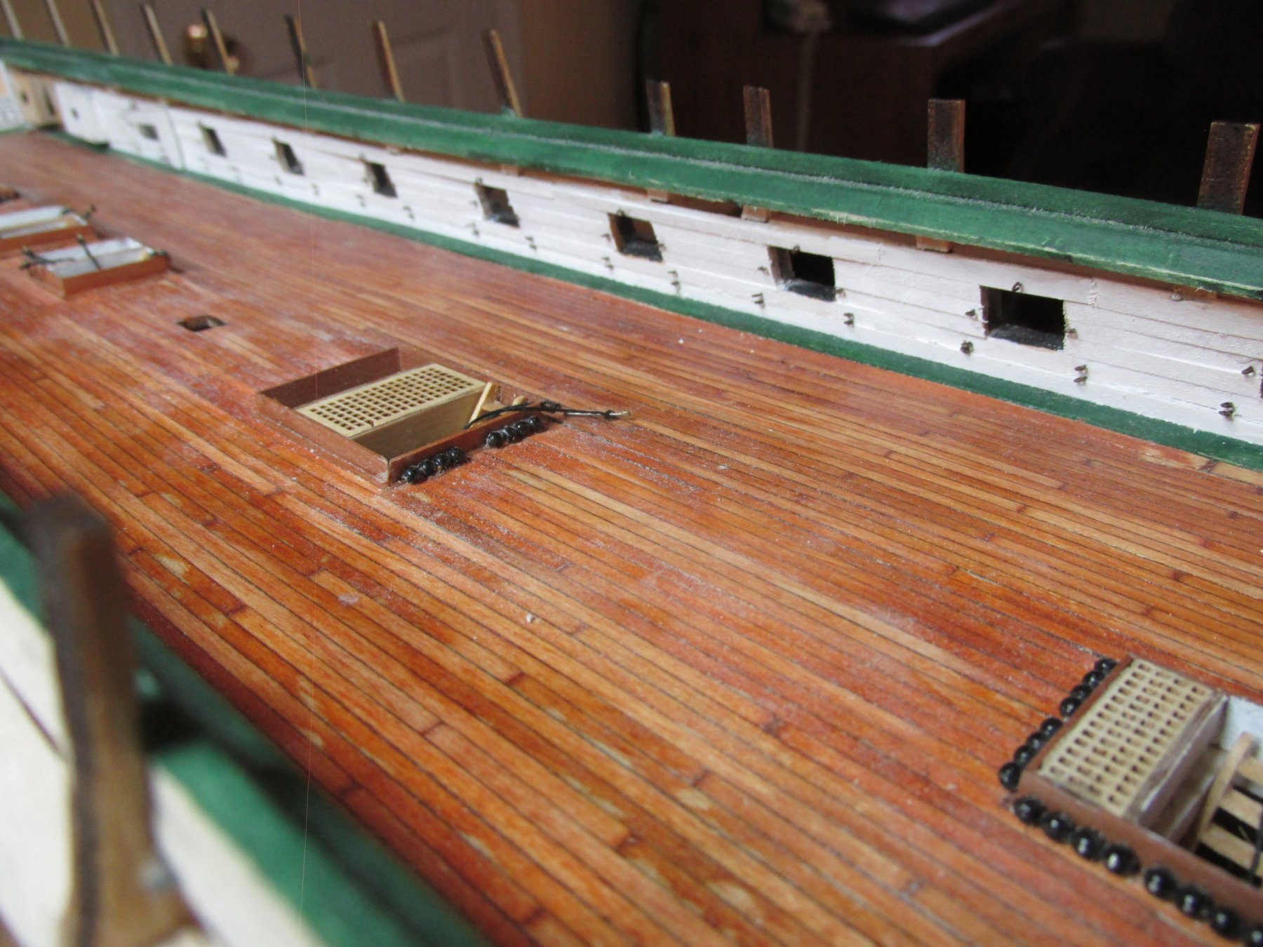
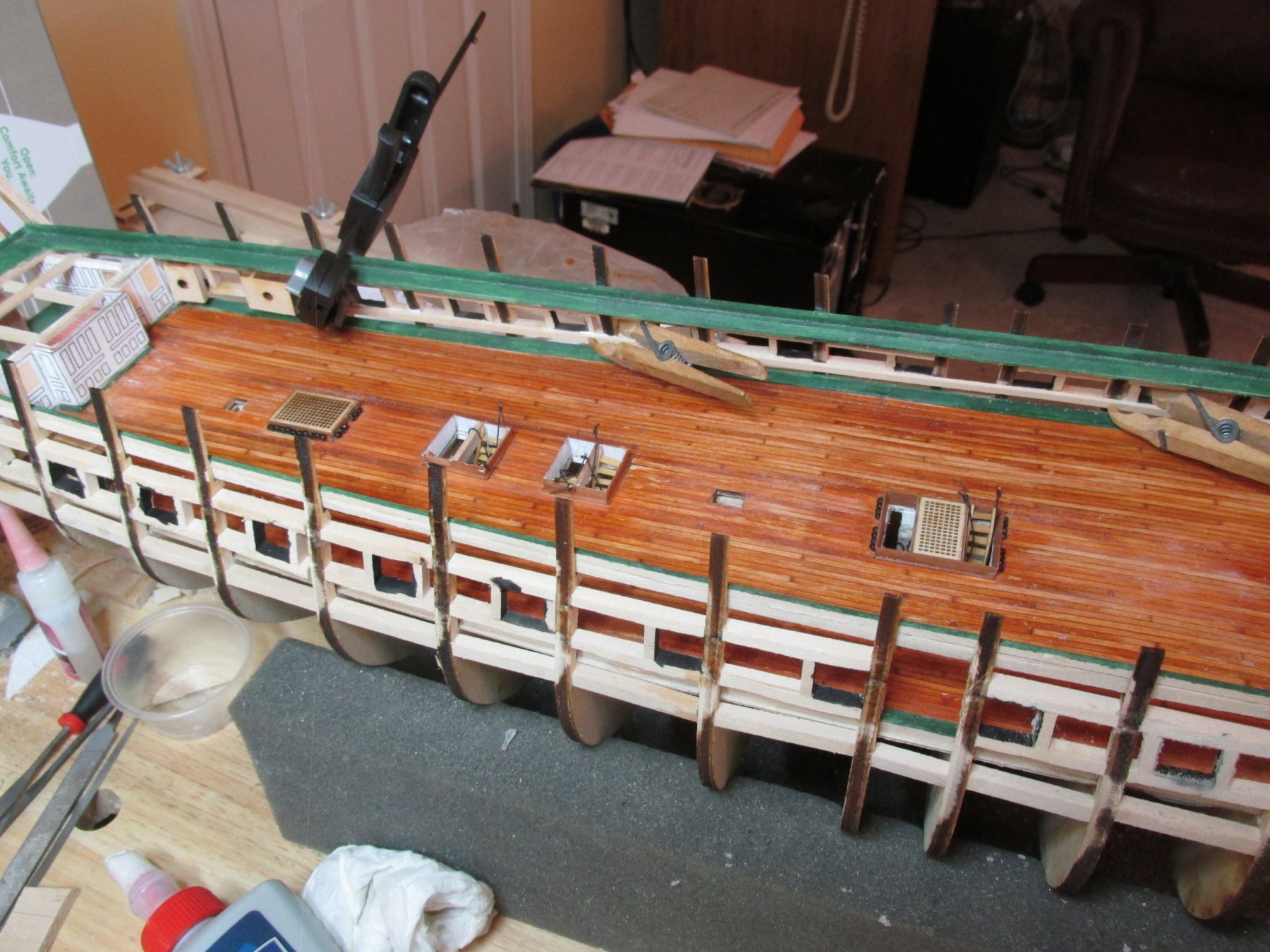
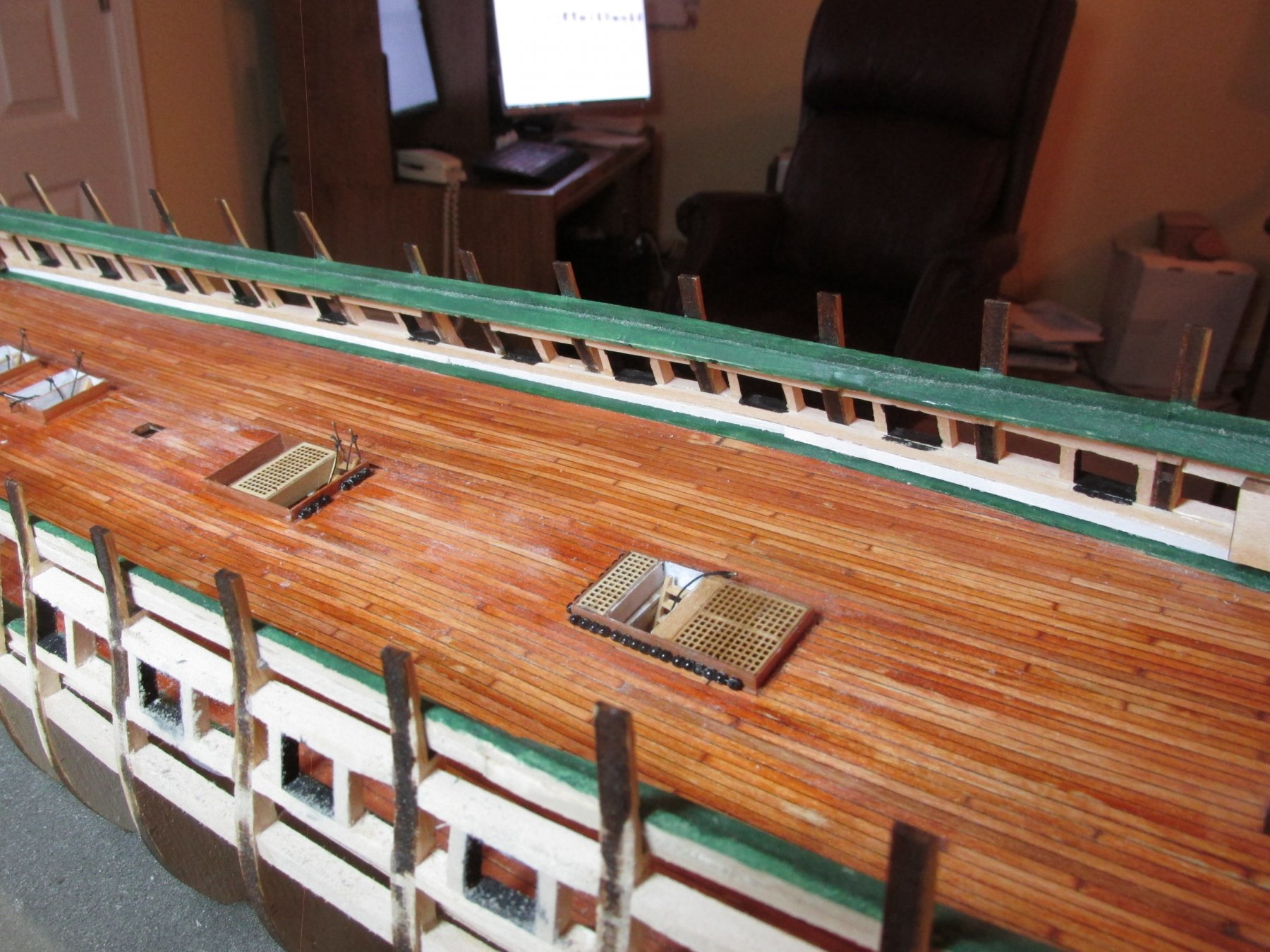
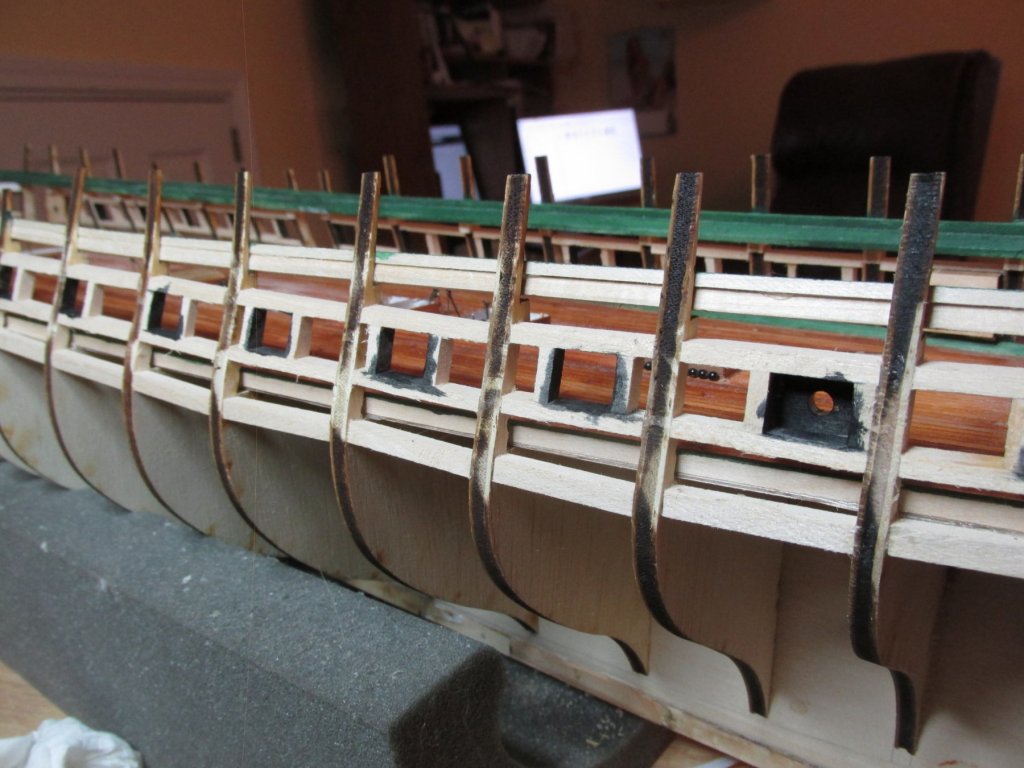
I’ve finally completed installing 154 eyebolts for the gun ports. I had to drill 7 holes per gun port using a push type hand drill: 2 sets of two for the breaching rigging, one eye bolt on either side of the gun port opening, one centered above the gun port opening. All, but the top vertical eyebolt, are orientated horizontally. The 1/16” eyebolts were pre-blackened, trimmed to size, and inserted into the drilled holes. I’ve now started to construct, position, and install the remaining hanging knees.

-
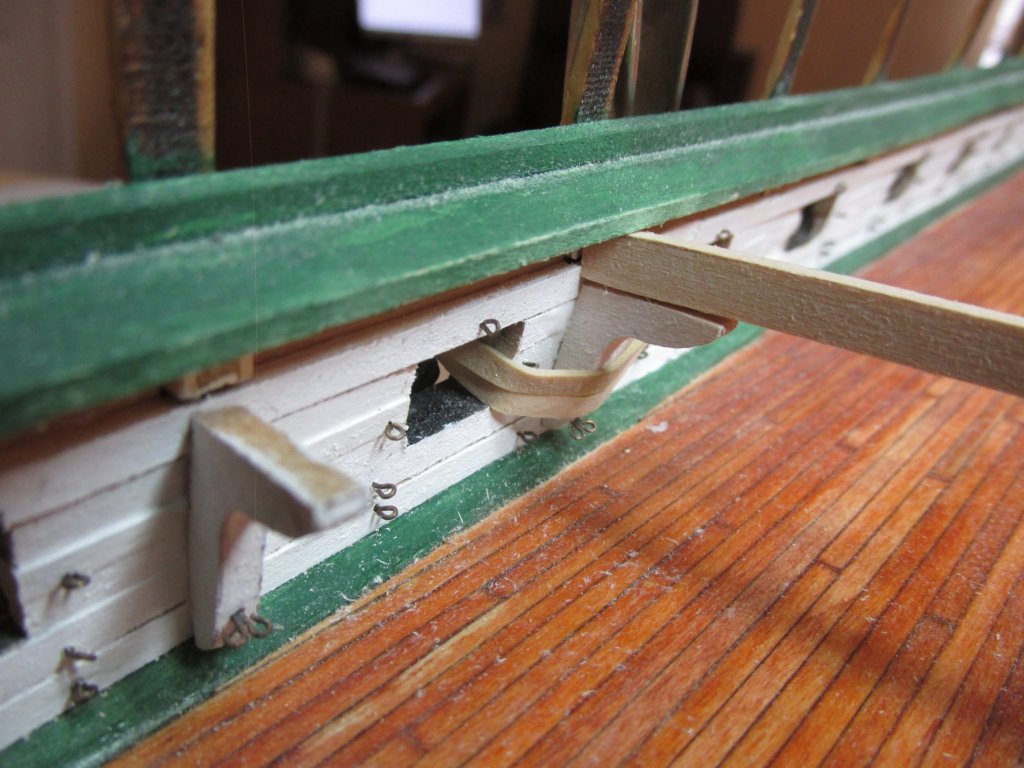
Walker_Wheeler - Considering that the pin stays are located on the gun deck bulwarks, and will be tucked under the spar deck planking, the dark lighting in that area, and the physical size of the hardware, using two eye bolts installed one over the other, no detail of the pin will be visible to the casual observer. The viewer will be looking through openings created in the spar deck where I will be omitting planking for that purpose. I could have done the something simpler for the double eye bolts located on the the hanging knees, but I wanted to try my hand at silver soldering to see if I could make something that looked like the real thing. I could, so I did. If that didn't work, I was going to use a larger eye bolt so that two hooks could be attached. The layman would not know the difference.
-
Those gun port covers look nice, but they may become problematic. They are delicate and have a tendency to be knocked off easily through the course of handling the model. If they do get knocked off, I'd leave them off till such time they are absolutely required. Jon
- 152 replies
-
- 2
-

-
- rattlesnake
- Model Shipways
- (and 1 more)
-
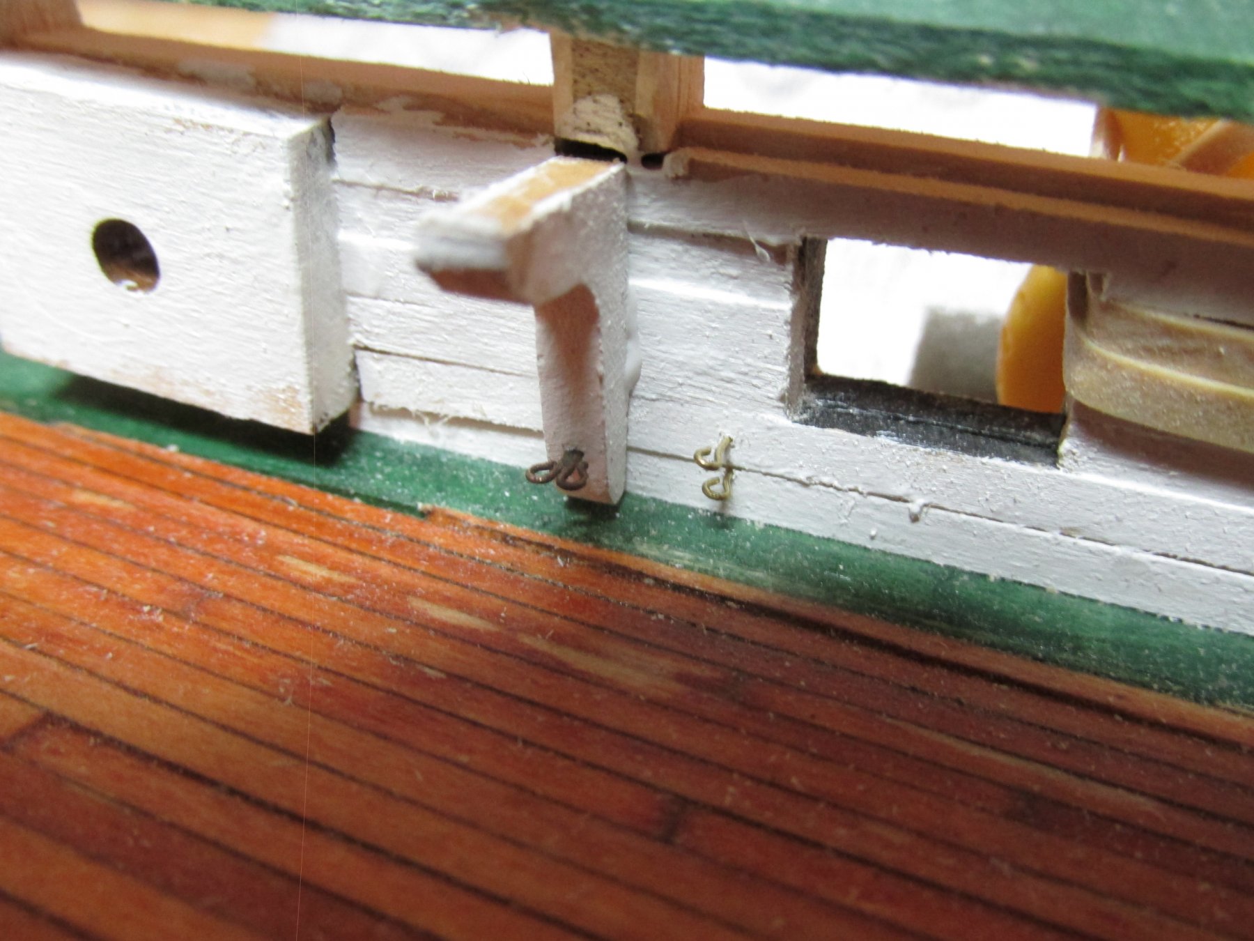
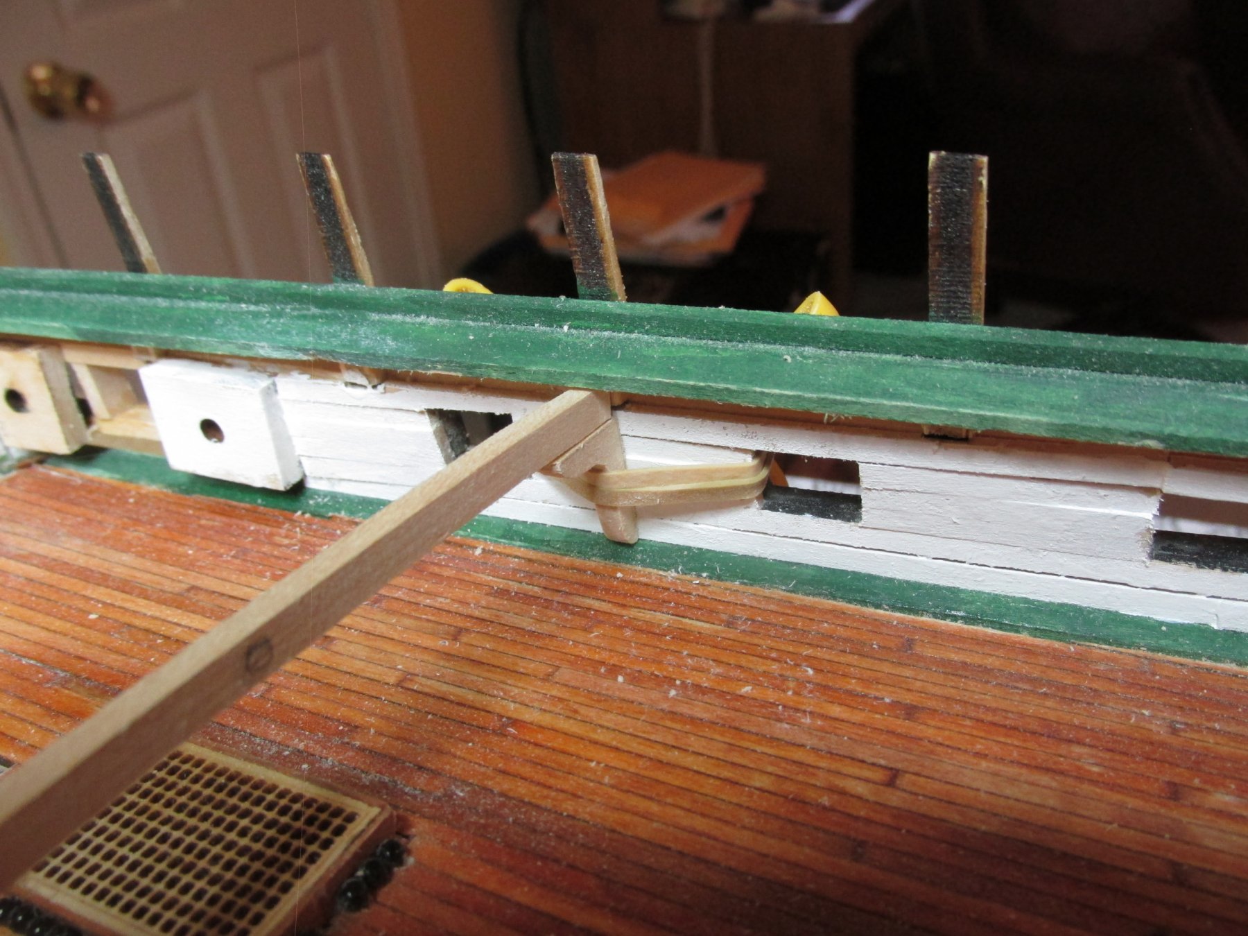
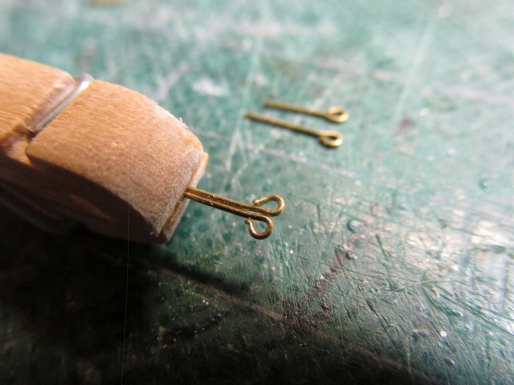
I decided to take the simple route for the breeching hardware and just used two 1/16” eyebolts. The hard part about this was drilling the holes into the bulkhead. Used tenacity and force of will to do that. That was proof of concept. Now I must do all of this again twice per gun port. Joy.

-
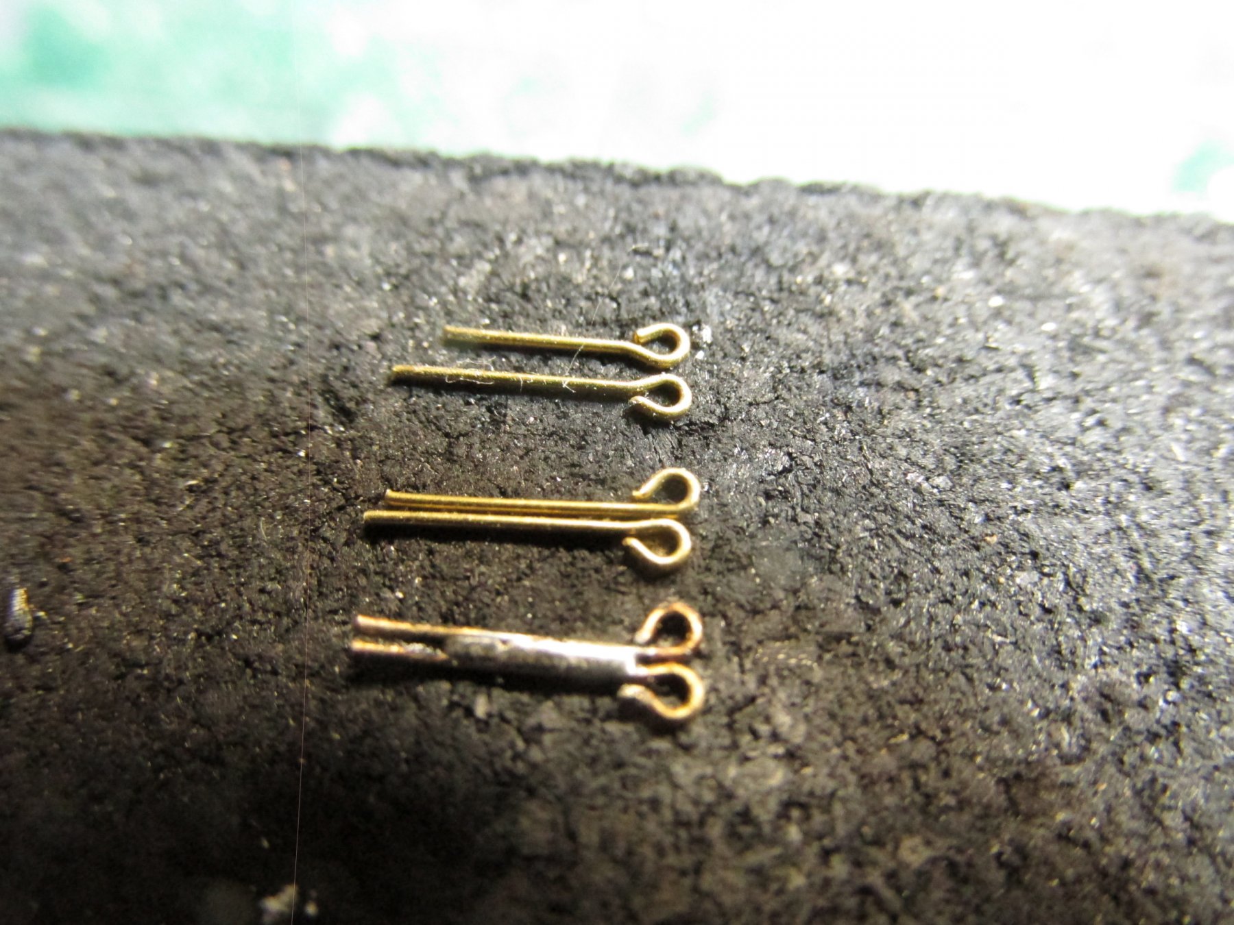
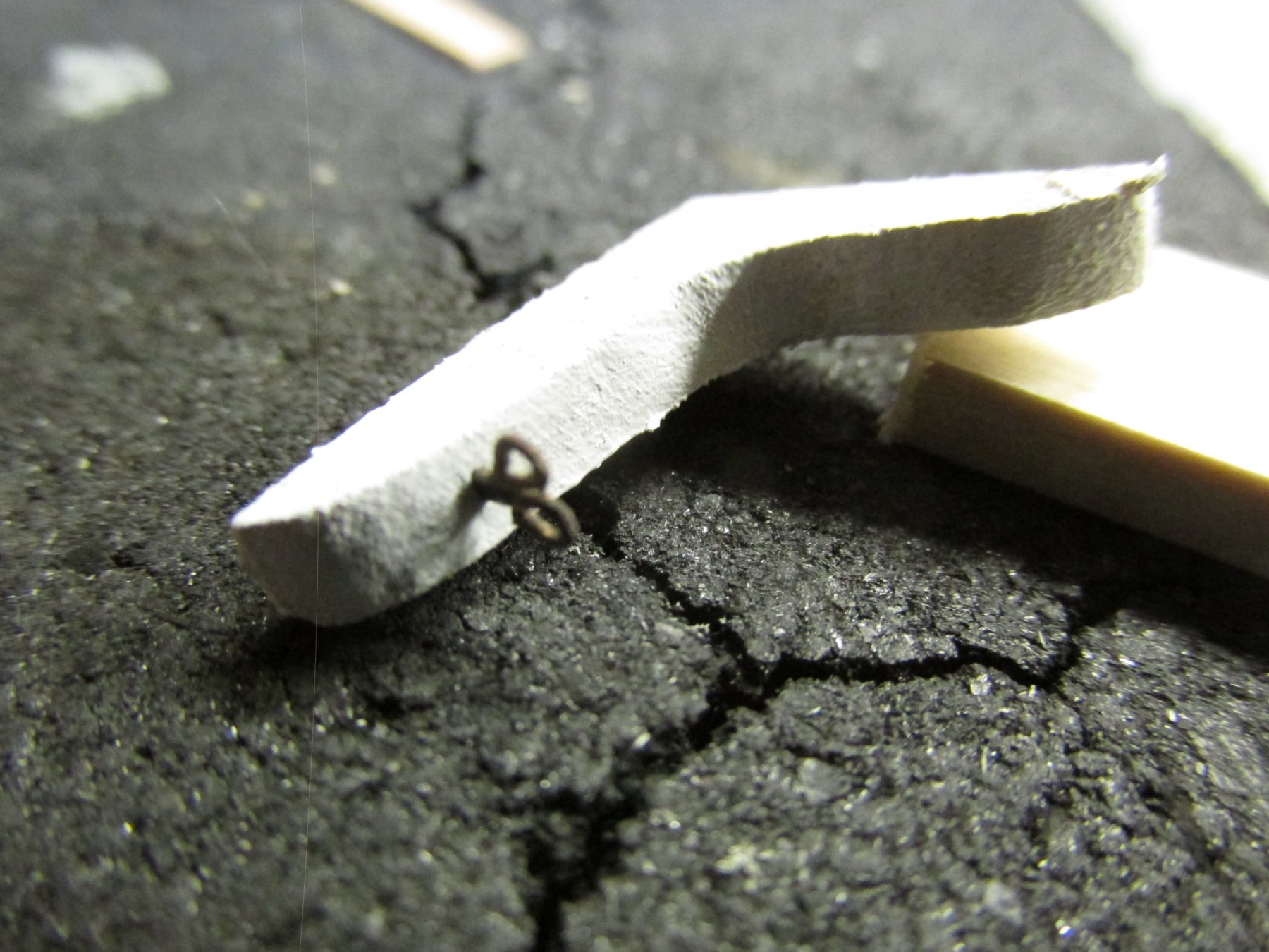
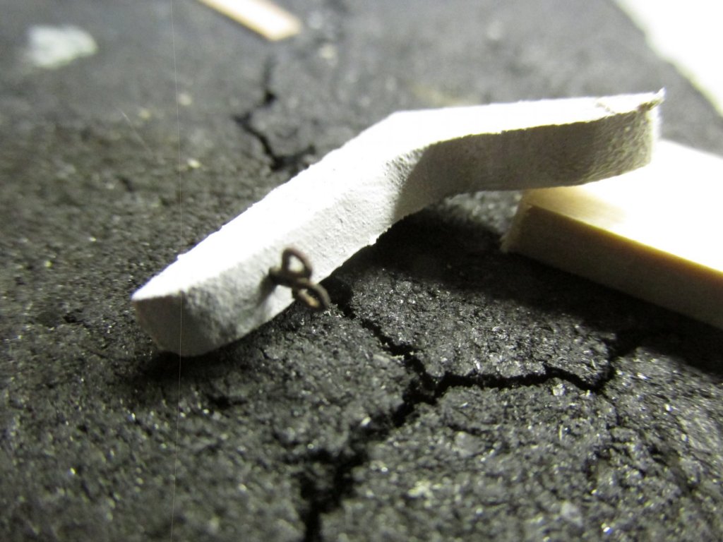
I took it as a challenge to create the double eyebolt, but it really wasn’t too difficult. Using 1/16” eyebolts, I bent the loop such that two eyebolt could lie next to each other without any overlap. These were placed into a slightly modified clothes pin used as a clamp and silver soldered together. I tried using silver solder paste but due to the small and rounded surface area, I could get the paste to stick where I wanted it or well enough. So, I resorted to using flux and a very thin sliver of silver solder from a roll. That worked great. After some filing, trimming, and blackening, I inserted the double eyebolt into the vertical knee.

-
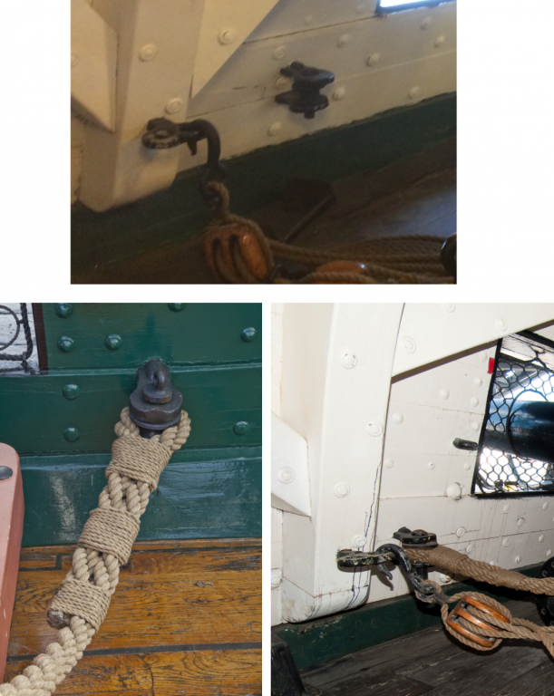
As it turns out, the rigging hardware are not your typical eyebolts. The side tackle of the gun hooks into a double eyebolt while the breeching tackle connects to two rings, one over the other, on the bulwarks using, such a seized loop of thick rope fits between the two rings and is held in place via a pin which drops through the top ring, through the loop of rope, and finally through the bottom ring. It appears the pin has a cap which prevents the pin from dropping all the way through.
-
The hanging knees for each brace must be custom made as the bulkhead changes angles along the length of the deck. But before any vertical knee is glued into place, the rigging hardware needs to be installed now. To do that latter, would make the task much more difficult.

-
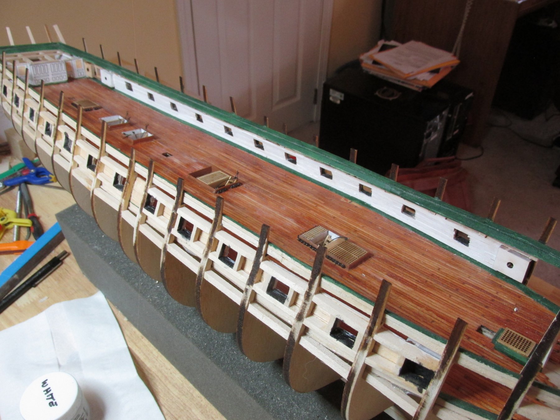
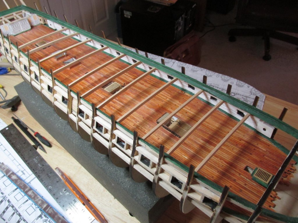
Gun Deck Hanging Knees & Gun Rigging Eye Bolts The order of installing the gun deck knees, as I’ve interpreted the plans, are first the vertical hanging knees under every other spar deck brace, next the diagonal knees and remaining spar deck braces above each gun port, (Whether I’ll make those braces completely or partially I’ve yet to determine), and finally the horizontal knees between the spar deck braces. Once all of this is installed, then I can work on building the gun carriages, mounting the guns and rigging them onto the model. I think I’m scaring myself. So, to paraphrase an old saying, a journey of a thousand miles starts with taking the first step. Following the US Navy Plans for the structure of the gun deck, they indicated that the spar deck braces do not always line up with the kit’s bulkheads. Those braces determine where the vertical knees are located. Therefore, the first thing I fabricated were the braces using 1/8” thick basswood stock. To ensure I had the proper beam curvature, I used as a guide the bulkhead spar deck braces, that I cut off from the bulkheads when I made gun deck. I traced the curves onto the basswood. Each brace was dry fitted into their proper location as indicated by the US Navy plans. They will be glued into place once the gun deck is completed
-
At first glance, it looked like you had the gammon chain coming through the seat of ease, but upon closer inspection it turned out to be a shadow. Nice job. Jon
-
K - Thanks for one of many welcome backs. It does feel good to be back at my shipyard. As for relying on my progress, well let's just say I'm not known for my speed. My next big milestone is the installation of the gun deck cannons. However, in order to do that, I wanted to install all the eye-bolts the cannon rigging will require into the model first. As it turns out, some of that hardware is embedded into the knees that support the structural beams for the spar deck. In order to install those knees with the required hardware, I am now in the process of forming the all those structural beams so I can fit the knees. tight against the bulwarks and the beams. Each one is a custom fit due to inconsistencies inherit in my woodworking skills. Not only that, Those eye-bolts aren't simple eye-bolt., They are double eye-bolts, so they have to be individually made as well. It seems that no matter what I have to do, I have to do something else first. So, to reiterate, you may grow much older at the rate I'm going. Jon
-
Thanks to all for the well wishes Jon
-
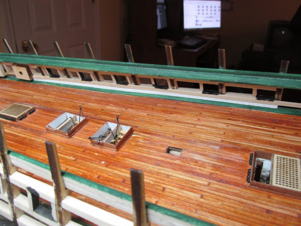
I just finished installing and painting the gun deck bulwarks. They didn’t come out as even as I would have liked, but by the time I add all the knees and bracings, guns, eyebolts, and furniture, these imperfections won’t be areas of interest to be noticed…I hope. Also, there still are a bunch of painting touch-ups on the waterways and inside the gun ports to be done. Right now, I think the diagonal knees and gun rigging eye bolts need to be installed next.

-
Just a quick note to let everyone know I’m finally back from surgery and rehabilitation. I had a large herniated disc in my lower back which required immediate removal. This was done through an incision in my abdomen by a surgeon who specializes in that sort of thing. A second surgeon worked from my backside to adjust my vertebrae angles with a wedge (screwed and pinned) where my disc used to be. And then the whole thing was fused together. All told they worked on me for six hours flipping me over four times. I was knocked out for eight. After spending 3 nights in the hospital working with occupational and physical therapists learning to walk with a walker, I went straight to a rehabilitation center for two weeks for addition therapy. By the time I left I had no need for any walking or stair climbing/descending assistance…for the most part. Surprising, I had very little pain as a direct result of the surgery. Of course, the pain killers might have something to do with that, but I don’t take anything during the day. I then spent a bit of time going through all my snail-mail as well as email, paying bills, etc., reacquainting myself with friends and family and the cat, who has not left my side since I returned. I’m just getting back to the Conny and will give you an update as soon as I hit a small milestone.
-
Thanks for the kind thoughts everyone. This will be my second, and more evasive trip to the surgeon. My first was 39 years ago and that worked great, so I have high confidence this time. JT, I know it's going to be painful due to my first surgery experience, but hopefully that pain will be the result of the incisions, etc., as opposed to my spinal defect (herniated disc) that is suppose to be corrected. I will be very happy if I'm back on my feet and on my own in 12 days like you. Jon
-
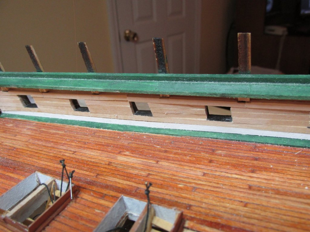
The bulwarks continue with short unpainted pieces in between the gun ports working upward. The excess wood that protruded into the gun port spaces were filed and sanded off. The bulwarks are no completed yet, but I will be taking a break for Thanksgiving week. The following week I will out of commission beginning that Wednesday as I prepare for lower back surgery which will require the services of two surgeons performing separate specialty tasks. I’ll spare you the details but suffice to say, I’m going to be poked through the front side as well as the backside. I don’t know how long recovery will be. The doctors re-assured me they do this all the time and they are confident of a successful outcome.

-
I glad you started yours before I did so that I would have another great log to follow. It is amazing that even after seeing what, and how you and many others did, I still managed to come up with new and original mistakes and do-overs. She sure is a great looking model. Jon
- 1,348 replies
-
- 2
-
-
- constitution
- model shipways
- (and 1 more)
-
I purchased the Model Expo USS Constitution Paint package, so I'm using their #MS4801, "Bulwarks Dark Green." I had not used much acrylic paint prior to the Conny build, so I can't comment as to how it compares with other brands. Other than the simple clean up, I'm not a big fan of acrylic. I find it does not spread evenly, and drys too quickly. out of the jar. Adding water is very critical - a little too much, it is too loose and it won't cover well. Too little, and the paint layer is too thick. Maybe it's because I have so little experience with it and I'm just not using it right. My sister, who is an excellent artist and paints ultra realistic, uses it all the time and get phenomenal results. I'll see her this Thanksgiving and hopefully get some pointers. Jon
-
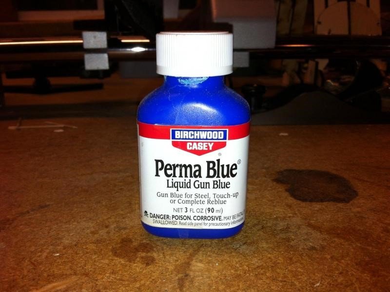
I don't know anything about guns or how to maintain them, but I did see something about using Birchwood Super Blue for blacking. Do you know if this stuff is the same thing as Birchwood Perma Blue?
-
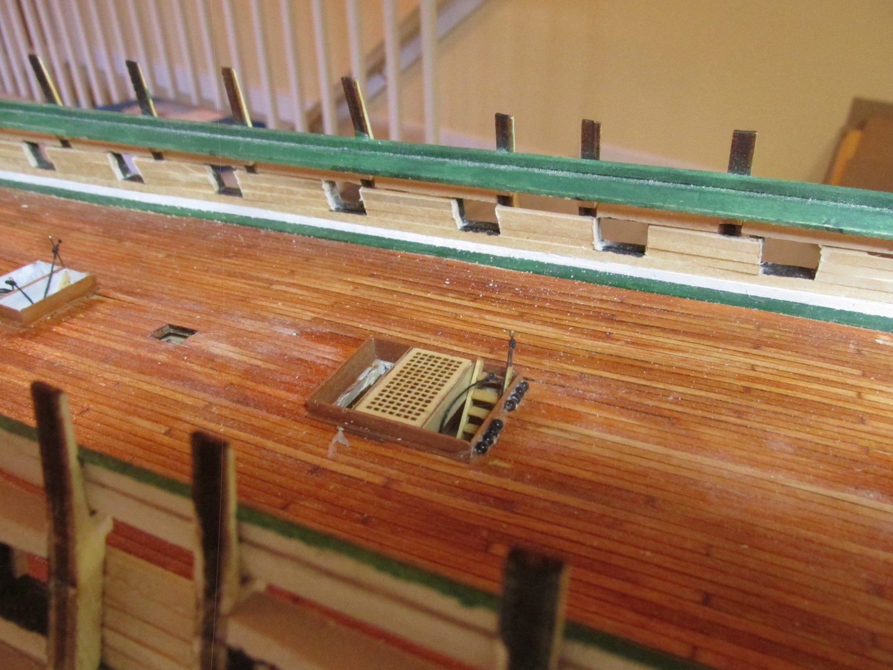
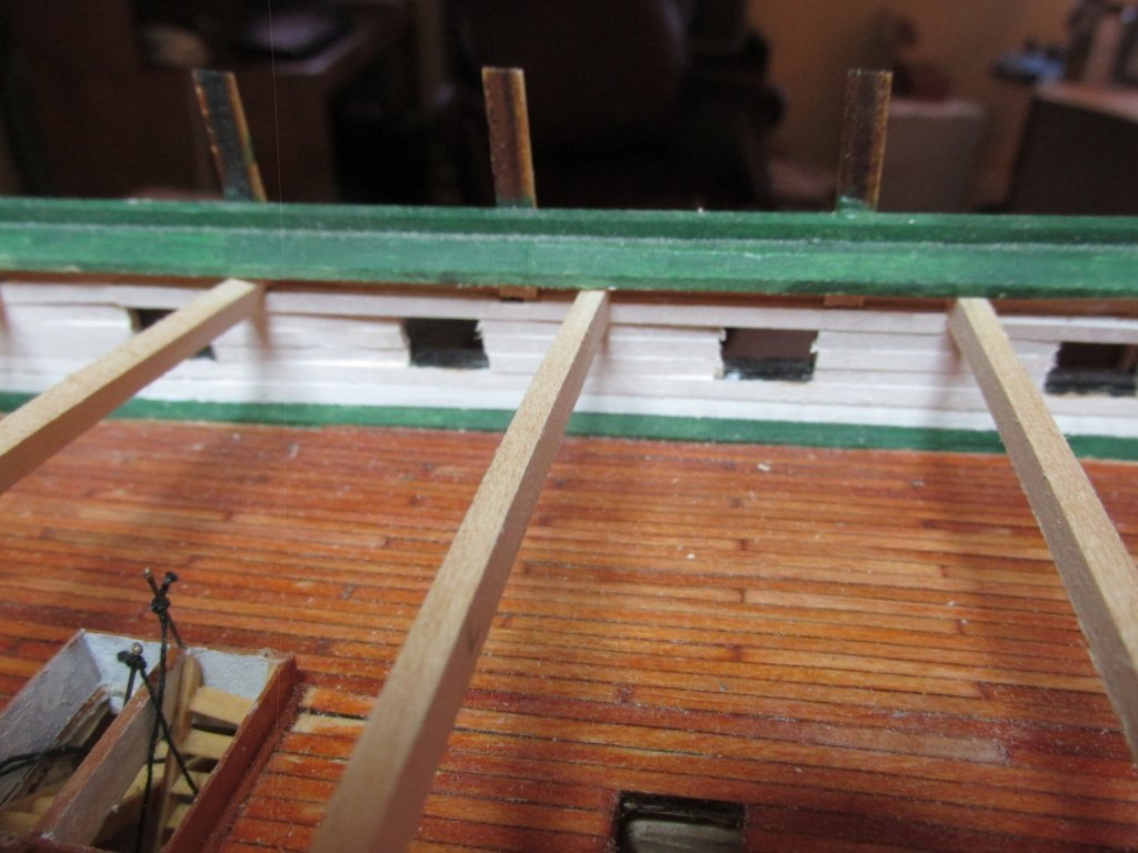
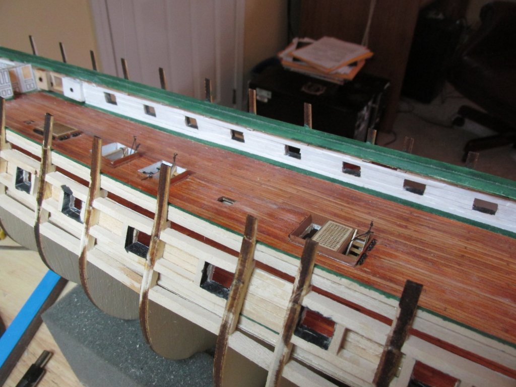
The first bulwark plank installed was a piece the full length of the visible gun deck placed flush with gun port sills on the port side. This acts as a baseline for the subsequent plank levels. The next plank was a pre-painted white, short piece placed at the aft end in between the waterway and the sill baseline plank. Because these planks must be custom fit due to the slight spacing irregularities between the waterway and the baseline plank, short pieces ease the fittings. It was pre-painted because painting these planks after installation so close to the green waterway would have been very difficult trying to avoid white paint spillover. The remaining planks will be painted white after installation. As you can see (or not?) the joints between the planks are all but invisible.


-
With the gun port netting detail dropped, I can now move on with the gun deck bulwarks. Looking at other builds, I’ve seen some builders make these bulwarks out of full width sheets of basswood or plywood because the surface is to be painted white, making any planking wood seams disappear. I find planking easier than custom fitting large pieces of inflexible wood. Once again, due to the poor visibility and the painting of the gun deck bulwarks, my choice of plank length will be based on ease of installment and not of historical size. The first thing I did, was paint the inside walls, sills, and headers of the gun port black. The subsequent planking will cover over any black paint spillover.
-
I think I might be able to help KHauptfuehrer. An excellent build log that shows all of the steps of mast and yard making, among a host of other details is Blue Ensign's Pegasus. In this case, start looking a post #112. As for the wood, if you don't want to buy dowels again, I would definitely NOT use basswood as it a bit too soft and doesn't hold an edge well. Boxwood is my choice. It's a bit harder, very fine grain, can hold an edge, and is still easy to work with. I hope this helps Jon
-
I finally got a phone reply from the USS Constitution Public Historian to my query about the gun port netting yesterday. (he was out of town for a week). He confirmed the netting is a modern safety feature, so scratch that detail.
-
I've been trying to get a response from the USS Constitution Museum's website and Public Historian (or anyone) about the gun port netting. All I get is silence. Was it added as a modern safety devise like the sprinkler systems, lighting, etc. or is it part of the ship's fittings? In other words, do I make it part of my model or not?
Thanks
Jonathan