HOLIDAY DONATION DRIVE - SUPPORT MSW - DO YOUR PART TO KEEP THIS GREAT FORUM GOING! (Only 20 donations so far - C'mon guys!)
×


JSGerson
-
Posts
2,611 -
Joined
-
Last visited
Content Type
Profiles
Forums
Gallery
Events
Everything posted by JSGerson
-
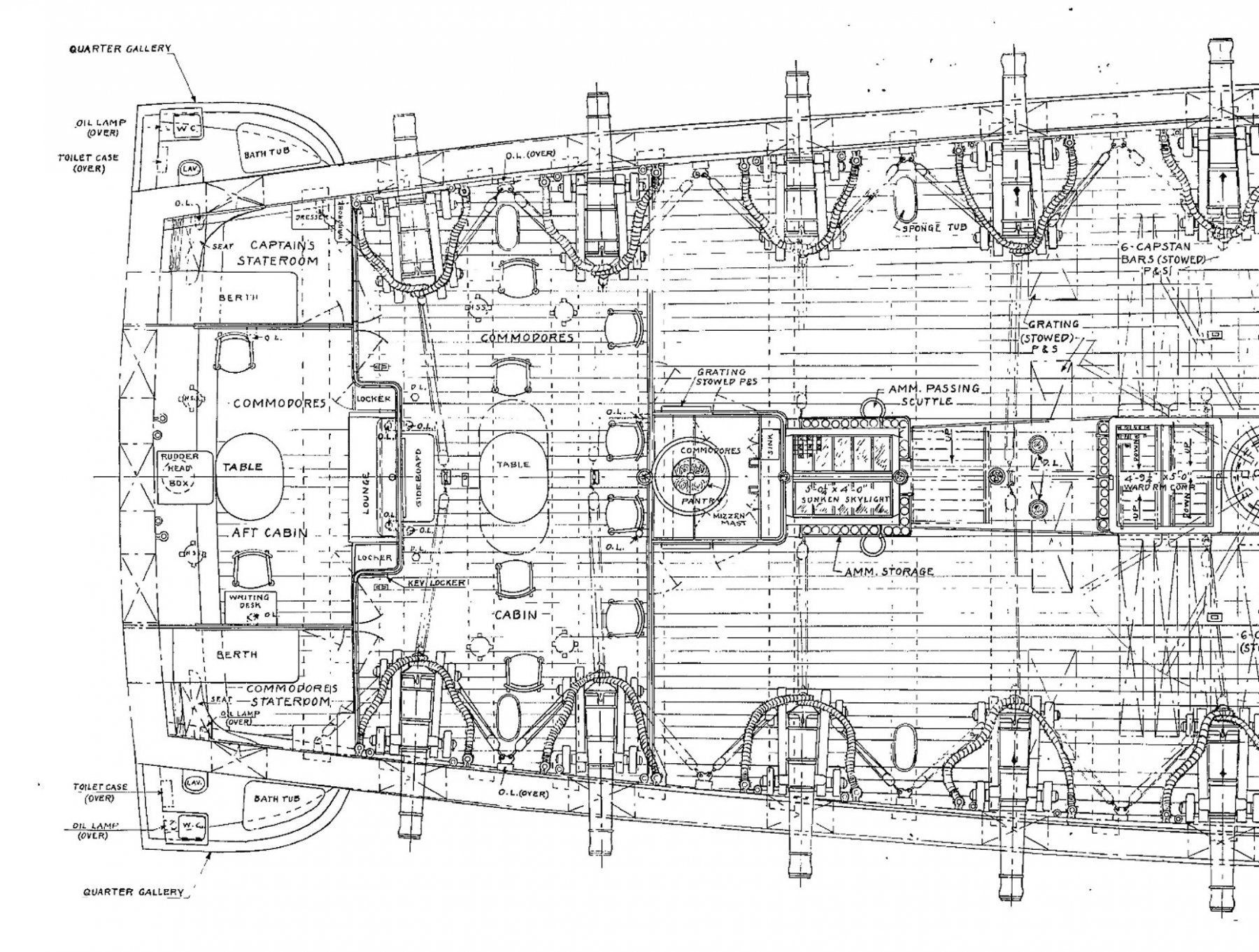
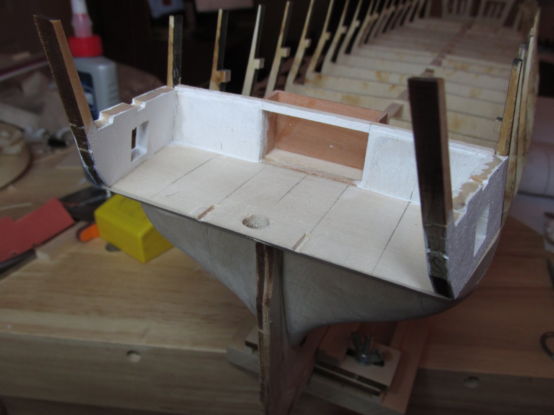
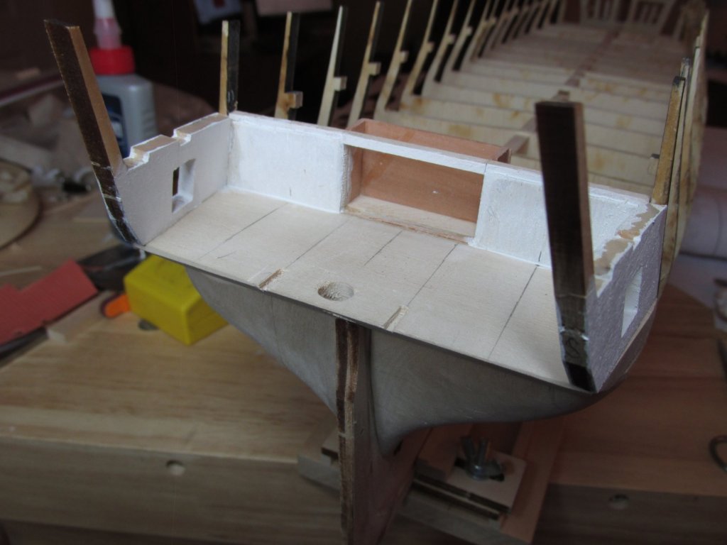
 Transom, Aft Cabin, Captain Stateroom…Still Using the US Navy plan for the gundeck as a guide, an opening was cut into bulkhead R for an alcove where presently a couch resides. Walls were fabricated, painted white (after photo was taken), and glued into place.
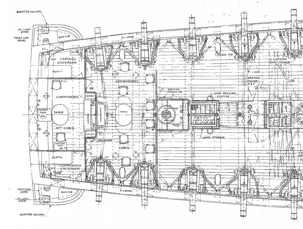
-
There's a lot of detail packed into those boats. Hope you have as much fun as I did making mine.
- 742 replies
-
- 4
-

-
- constitution
- frigate
- (and 1 more)
-
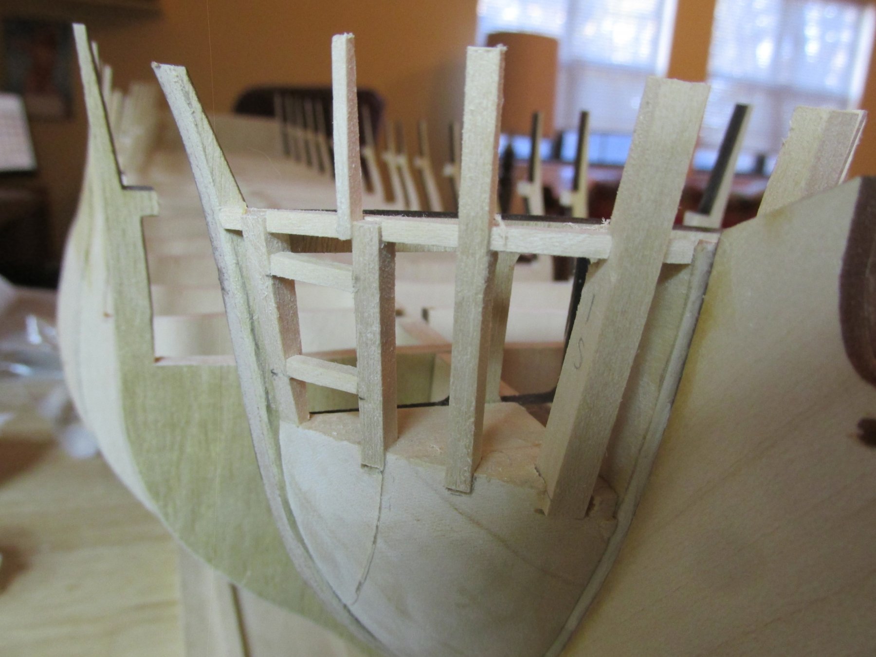
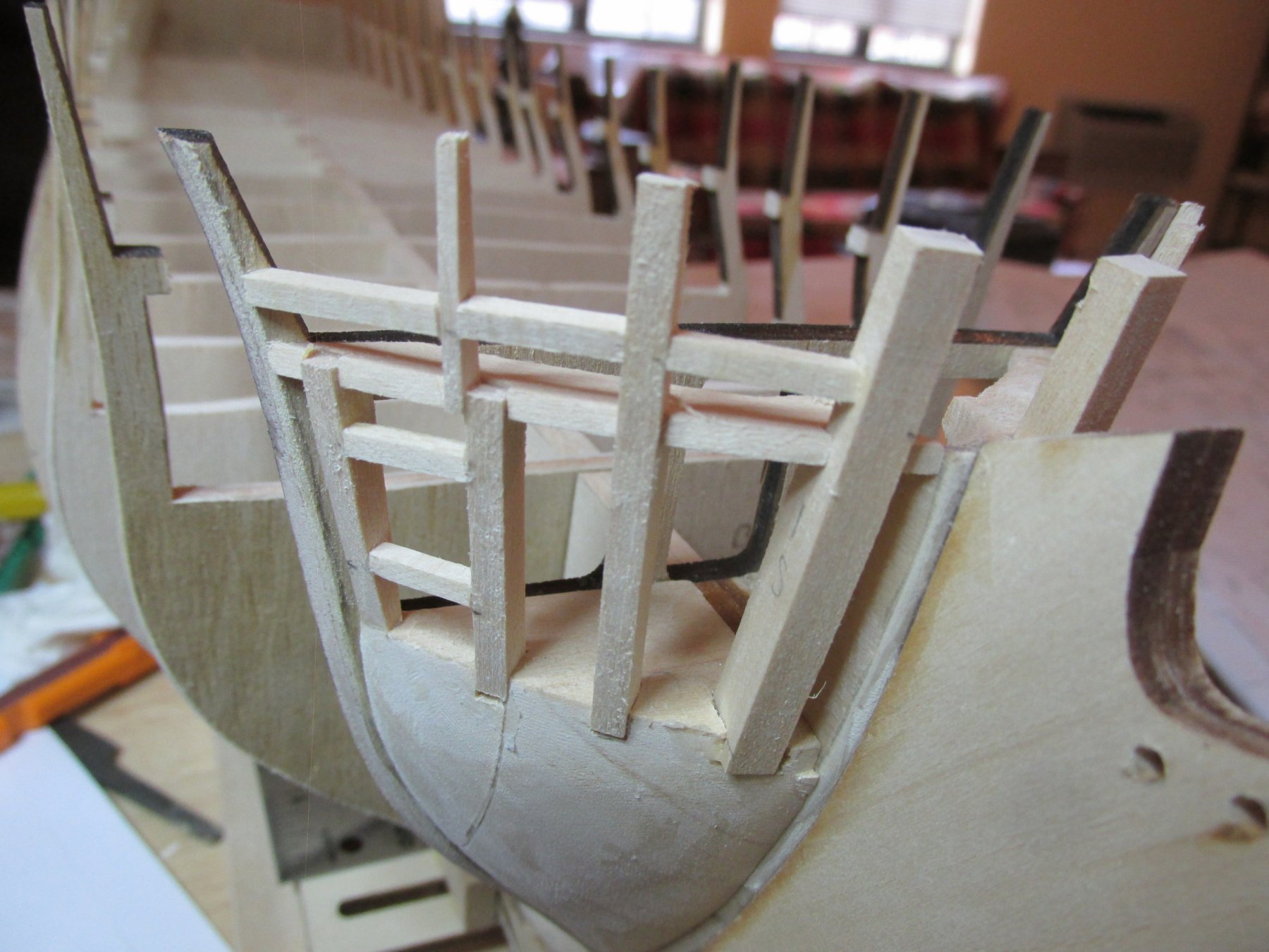
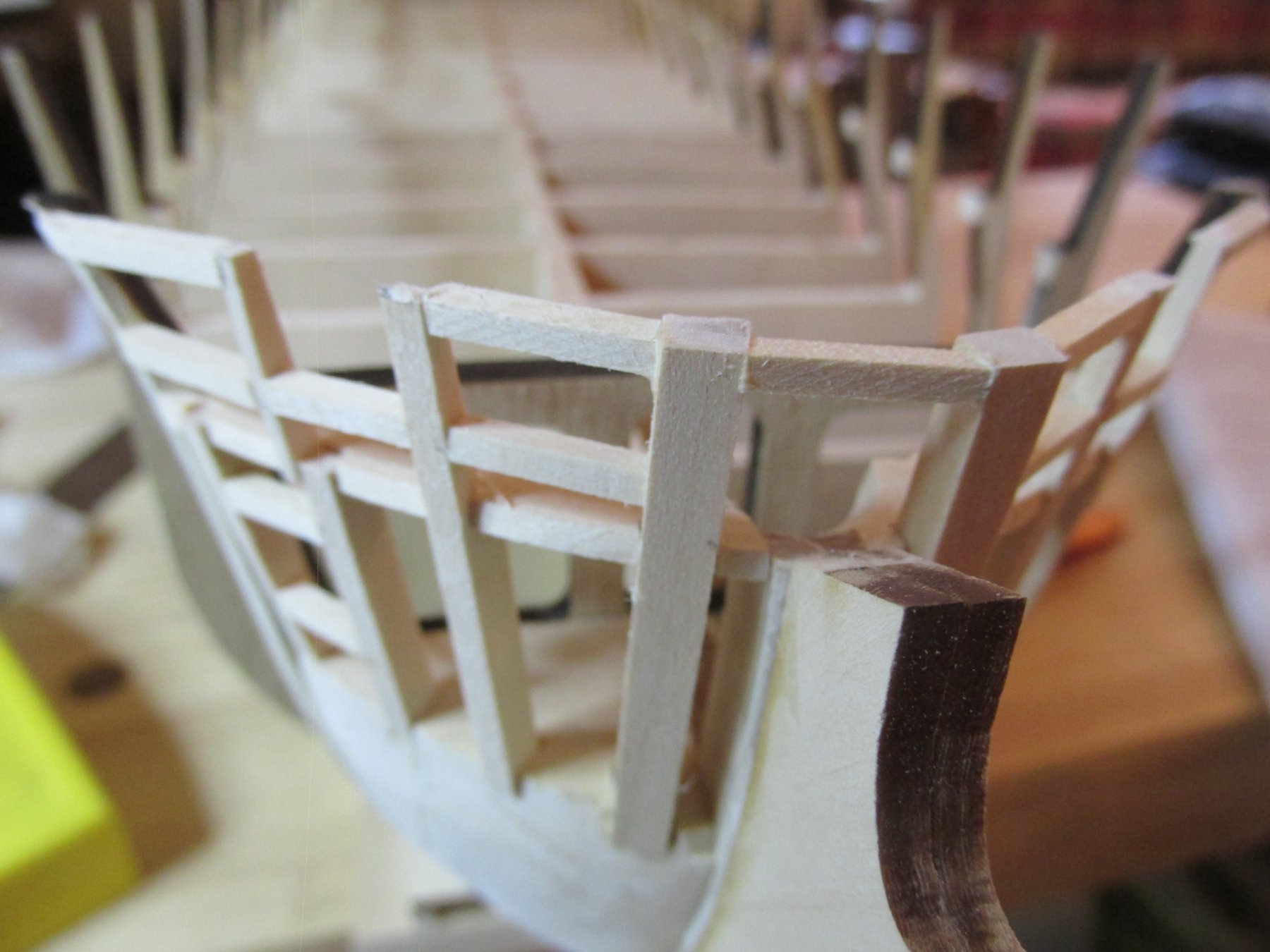
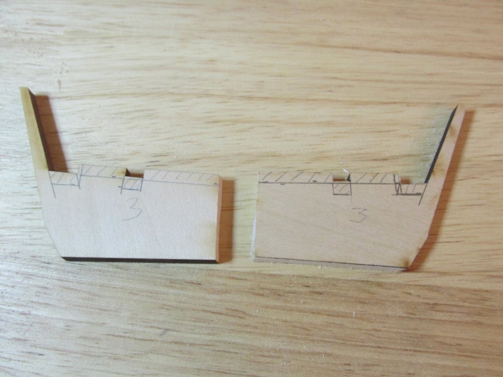
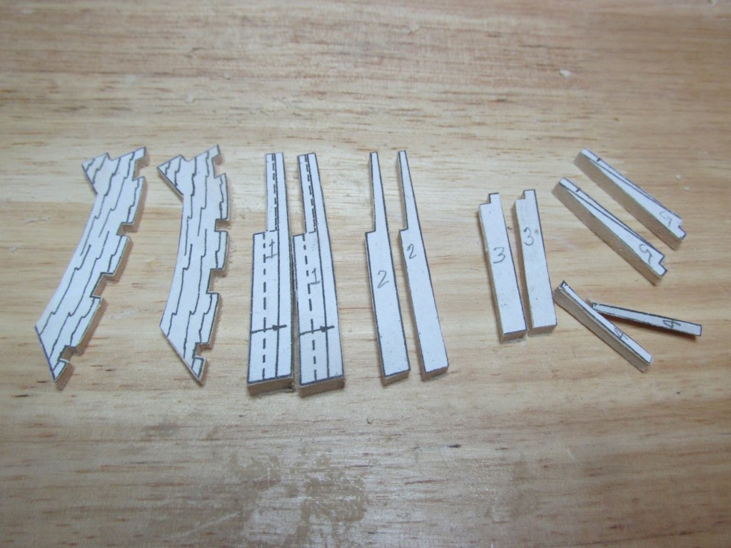
Problem I’ve been going over and over the stern bash working out first, what I want as a final product and second, what do I have to do to get there. Basically, bulkhead R and the stern frames must be modified. In the process of doing this, I discovered I have a major error: my unmodified stern frames are off vertically by an 1/8”. If the frames were to be installed as called for by the kit plans, the tops of the stern frames should be flush with the top of bulkhead R to support the planking. In my case, the frames exceed the height of the bullhead by 1/8”. Reading Robert Hunt’s practicum at the end of section 2.2, he states: “…my transom frames [are] sticking up higher than they should. This is because my counter piece was too thick…” He then goes on to say he corrected the problem but did not discuss why it happened nor how he fixed it. Either there is a design flaw in the kit, or he and I committed the same error somehow. Now the good news is because I already planned to modify the frames, I should be able to correct the problem. I just don’t know where I went wrong. Unlike Mr. Hunt, my counter piece appears to have the correct dimensions and is seated flush right on the keel frame. All the individual parts appear to have the proper shape and dimensions, all the reference lines line up, and the parts fit like they are supposed to… except when I measure them as a whole. I’m 1/8” too tall. I need to remove that 1/8” but from where? I don’t want to fix one problem only to create others further into the build. As I see it, I really have only two options: I can either remove the 1/8” from the top of the frame or I remove it from the bottom. If I remove the excess material from the bottom of the frames, I will be changing the exterior shape of the stern. If I remove the material from the top of the frames, I am only affecting the interior of the stern. In effect I would be lowering the internal structural support to line it up with the remainder of the bulkheads. If this were a real ship, it would be like lowering the stern gundeck ceiling 9.6”. So, lowering the ceiling is what I’ll do. I still don’t know where I messed up. Here in the picture below are the #3 exterior frames with the mocked-up corrections. The internal frames will have extensive modifications including the error correction and still need to be designed.
-
With regards to the gunport spacing, or any other dimensional detail, I always check the US Navy plans. As I read it, the spacing is close but not consistently the same. From a distance, the eye may not see the differences. Jon
-
I'll say this, you have courage, tenacity and are stubborn. But, I glad you made all the trial and error attempts so that I could profit by it and avoid all the pitfalls you've revealed. Thank you. BTY, any chance you could post larger size images the next time? Jon
-
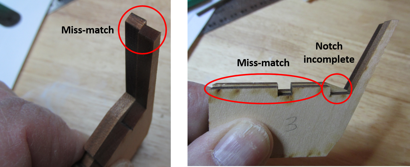
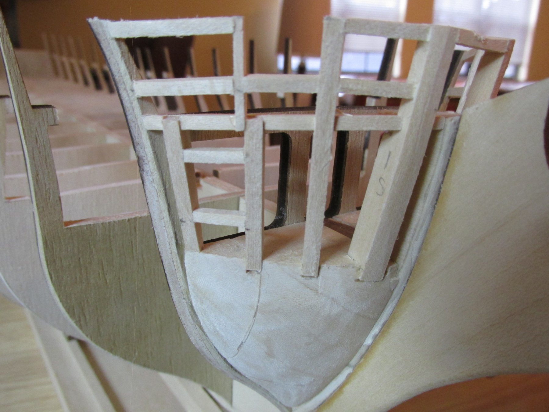
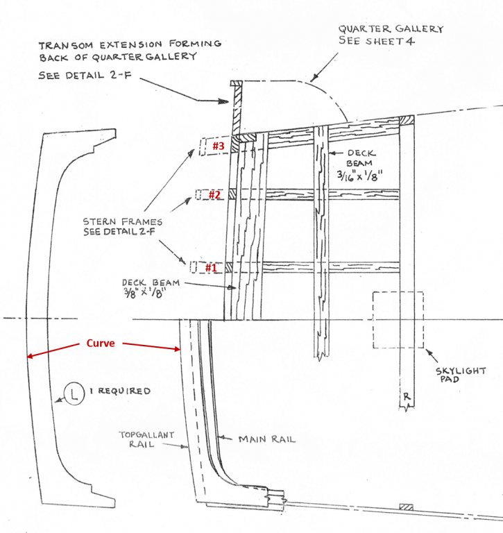
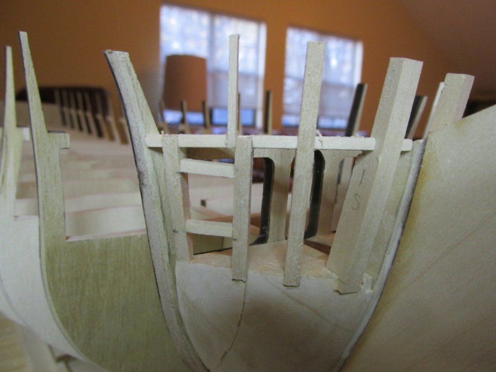
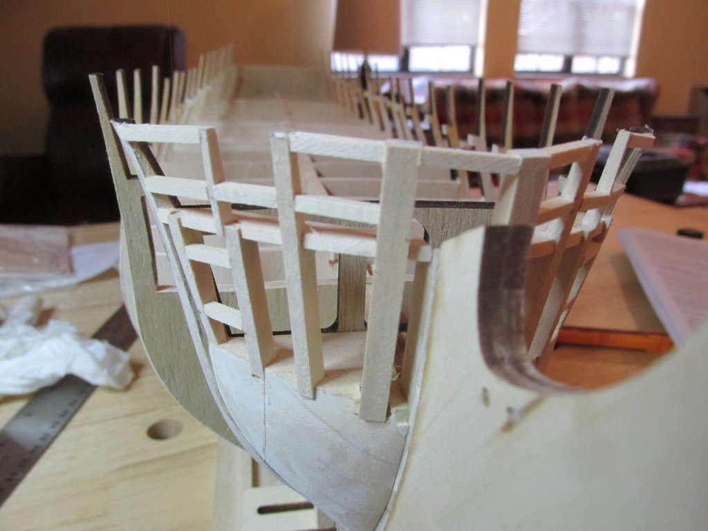
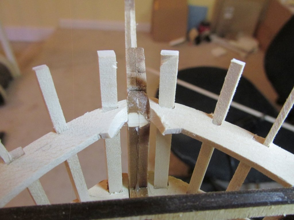
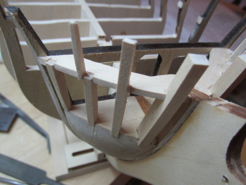
Stern and Transom From what I have read, the stern and transom seem to give a lot of builders, fits, I’m no exception. Just look at my Rattlesnake log. I decided that if there were going to be windows in the transom and quarter galleys (which there will be), then there ought to be something inside to see through those windows (never mind poor internal lighting and confined space). That means I must alter the kit’s method of forming them. To do that, I need to understand what is the kit’s method, so I can alter it to my needs. My plan of attack was to mock up the stern based on the kit’s instructions and then make plans for the alterations. The kit provides 6 laser cut stern frames to sit on the stern counter to provide the support and create the shape of the transom. Those frames are almost identical to each other save for the two outer pieces (#3) which are a bit thicker and have subtle angle changes. I don’t know if #1 and #2 are supposed to be different, but I can’t tell the difference. Right off the bat, I had a minor problem, one of the two #3 pieces was not formed properly. This by the way is not unique to me. I noticed this flaw in at least one other build log. Another problem that seems to catch a lot of builders off guard is the subtle curve of the transom as seen in the plan view. If the builder was careful when he created the stern counter, it should have been noted. The problem usually rears its ugly head when installing the laser cut the taffrail. Bob Hunt in his practicum made me aware with his warning. He stated that nowhere, either on the plans or the instruction booklet, is this curve specifically addressed. The problem arises because the 6 laser stern frames tend to create a flat transom surface as apposed to a slightly bowed one. Based on and inspired by CaptainSteve (he’s doing a more extensive modification), It now appears that I will have to modify the 4 inner frames (#1 and #2) to allow me to create an open space for the Captain’s area and hopefully, I’ll address the errors I’m aware of and not create any new ones. I’m really flying without a net as I have never kit bashed without someone’s detailed instructions to follow. CaptainSteve has not finished his modifications or at least documented them so far.

-
Once the glue, dried overnight, the bow was sanded to create a smooth surface, by beveling the installed pieces.

-
Next, the header and sill for the bridle port were installed using 3/32” x 3/32” stock. Finally, the stiffeners were added also using the 3/32” x 3/32” stock


-
After reading another build log, it was brought to my attention, that I should check the fit of the bowsprit. It was a good thing that I did. The dowel that will be use for the bowsprit did not fit. With the help of my rotary tool and a drum sander, that was quickly resolved. It is a lot easier to adjust that now, rather that latter.

-
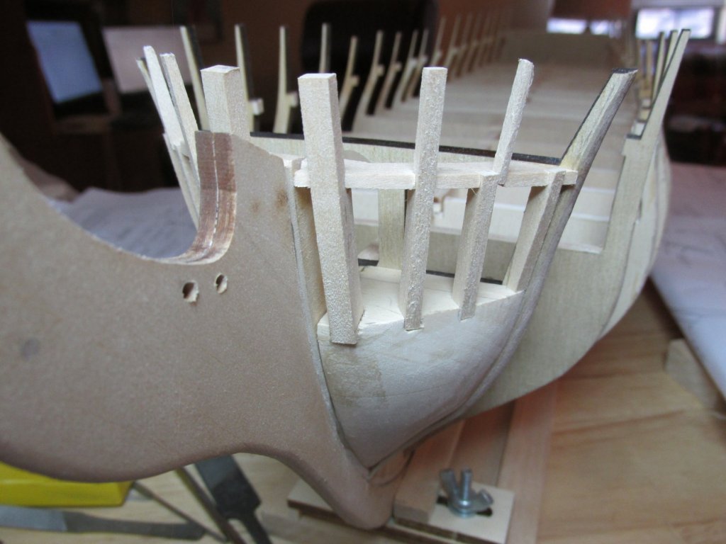
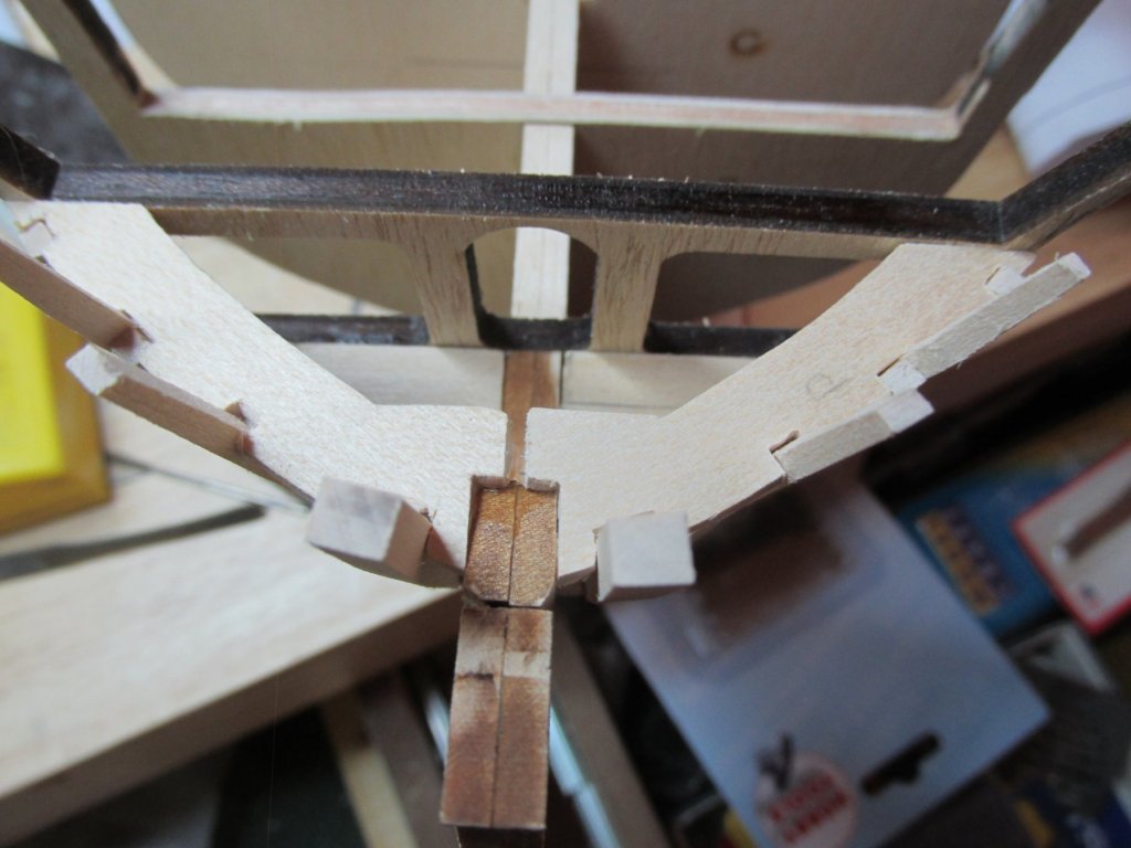
Bow Knightheads and Timberheads The bow knightheads and timberheads are those vertical structural members at the front of the ship. The knighthead is the member which is next to the stem. I didn’t know that as I had to look them up. Anyways, in order to follow the plans exactly as drawn, I continue to use copies of the plans as templates marking each piece with their appropriate identifications. The plans don’t specifically state use a particular piece of wood stock, so I checked with Robert Hunt’s practicum to see what he used. What he chose made sense; so, I did the same: Spar Deck Framing – 3/32” #1 - 5/16” x 3/16” #2, #3, & #5 – 1/8” x 3/16” #4 – 1/16” x 1/8” The practicum started with fitting and gluing the knighthead (#1) and then #5 to align the spar deck frame. I found it easier to install the spar deck frame first and then used it to align the remaining parts. After a lot of dry fitting of the pieces singularity and all together to ensure proper alignment, they were glued in with wood glue. What I noticed was that although I meticulously followed the template, the notches in the spar deck frame were not exactly the right dimensions. Some fudging had to be done.

-
I was thinking that he could show us how to broadcast through the website, if it was possible.
- 742 replies
-
- 4
-
-
- constitution
- frigate
- (and 1 more)
-
Try contacting Chuck. He's the best one to know since he runs the website.
- 742 replies
-
- 2
-
-
- constitution
- frigate
- (and 1 more)
-
I live in Aiken SC, about 3 hours away or so from Lumberton. It would be nice to have a local group of fellow wooden model enthusiasts. Jon
- 742 replies
-
- 4
-
-
- constitution
- frigate
- (and 1 more)
-
May I suggest that (if you haven't done so already) that you do NOT glue the bottom layer to the rest of the stack. This will allow you carve the interior of the hull a whole lot easier. Once that is done, then attach the bottom layer. Jon
- 742 replies
-
- 6
-
-
- constitution
- frigate
- (and 1 more)
-
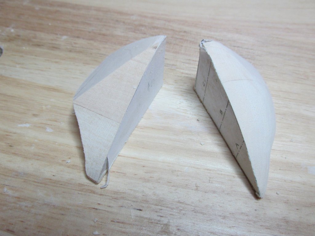
At this point, the templates were removed, and new ones for the notches were put on the top surface. These were for the gunports and head access frames. These were delicately cut out with an X-axto knife with a fresh blade. Even then, I managed to crack one of the blocks near the big edge notch. PVC glue was used for the repair and I waited 24-hours for it to set to ensure a strong bond. These were then glued into place.

-
Bow Filler Blocks I had anticipated that the bow filler blocks would go as easy as the stern blocks. Well they did…and didn’t. The initial cuts on the scroll saw went as planned, following the pattern on the templates. Removing the remaining excess wood took a bit longer than I expected. After removing the remaining bulk of wood with the disk sander, I was constantly checking the block on the bulkheads to see if a plank would fit around the curves. The one thing I feared was taking too much off or taking any material off in the wrong place. So, a little bit at a time, with constant checking, using just files, I believe I managed to get the proper shape. This took quite a bit of time. Patience, tenacity, and perseverance are the key.
-
Geoff, you are so right. That is why I haven't posted anything yet for the bow filler blocks. I keep testing and finding I need to remove juuuuusst a bit more here and then there. So I'm taking my time. Jon
-
Mike - Surprisingly, I did not find it that difficult. However, That can not be said of the bow filler blocks, for me at least. Pictures and commentary to follow soon.
-
Just found your build log today. There is some real good stuff here so I'll be following you with great anticipation of more good stuff. Jon
-
Just discovered your build log. I look forward to following your progress as I am a few months behind you. Jon
-
Those boats are fun little projects. I did mine first as an appetizer for the main course, the ship itself. Even though the MS kit's plans were very close to the US Navy plans (CD from the museum), I used the US Navy plans directly when ever I could. Jon
- 742 replies
-
- 4
-
-
- constitution
- frigate
- (and 1 more)
-
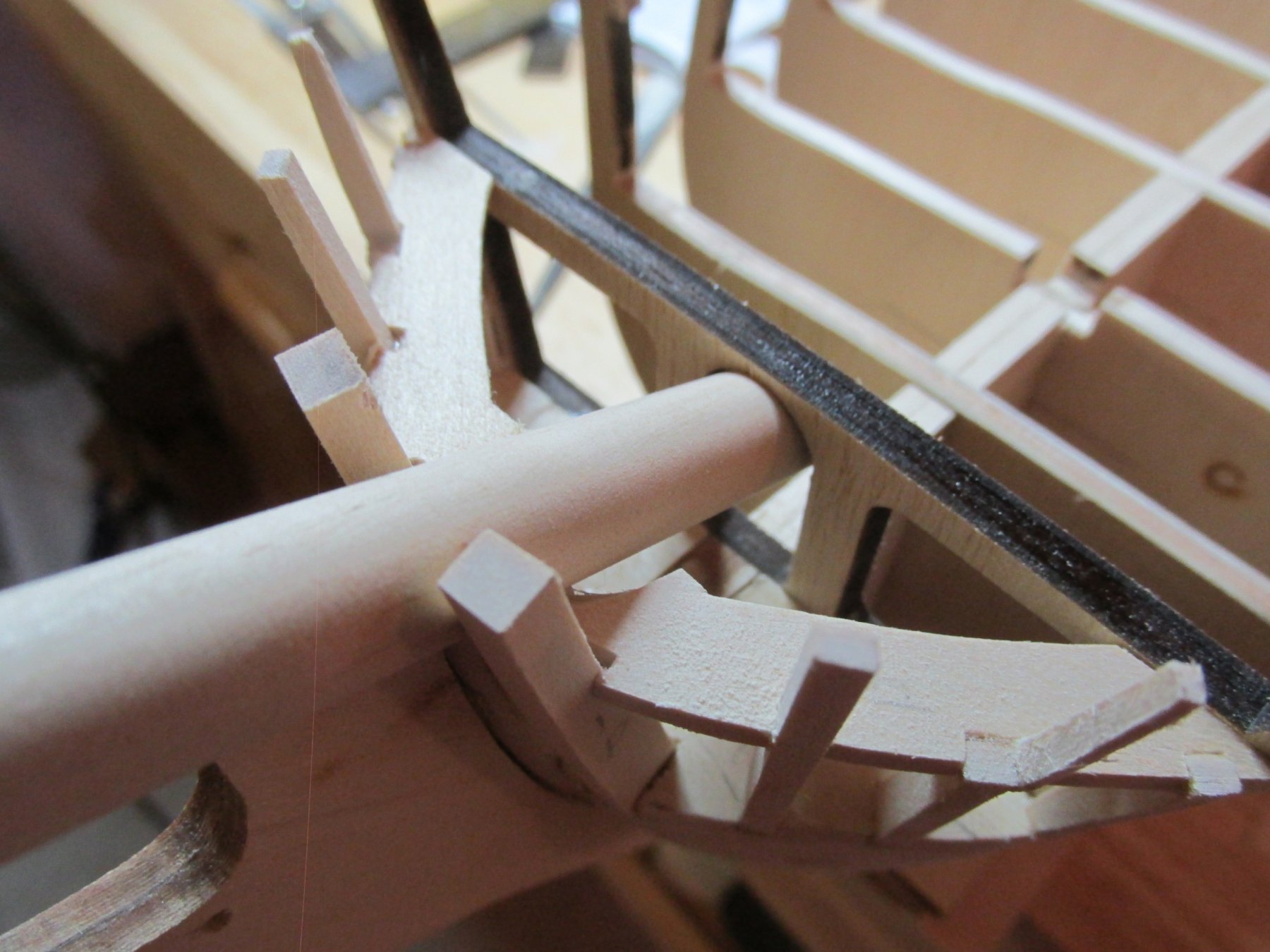
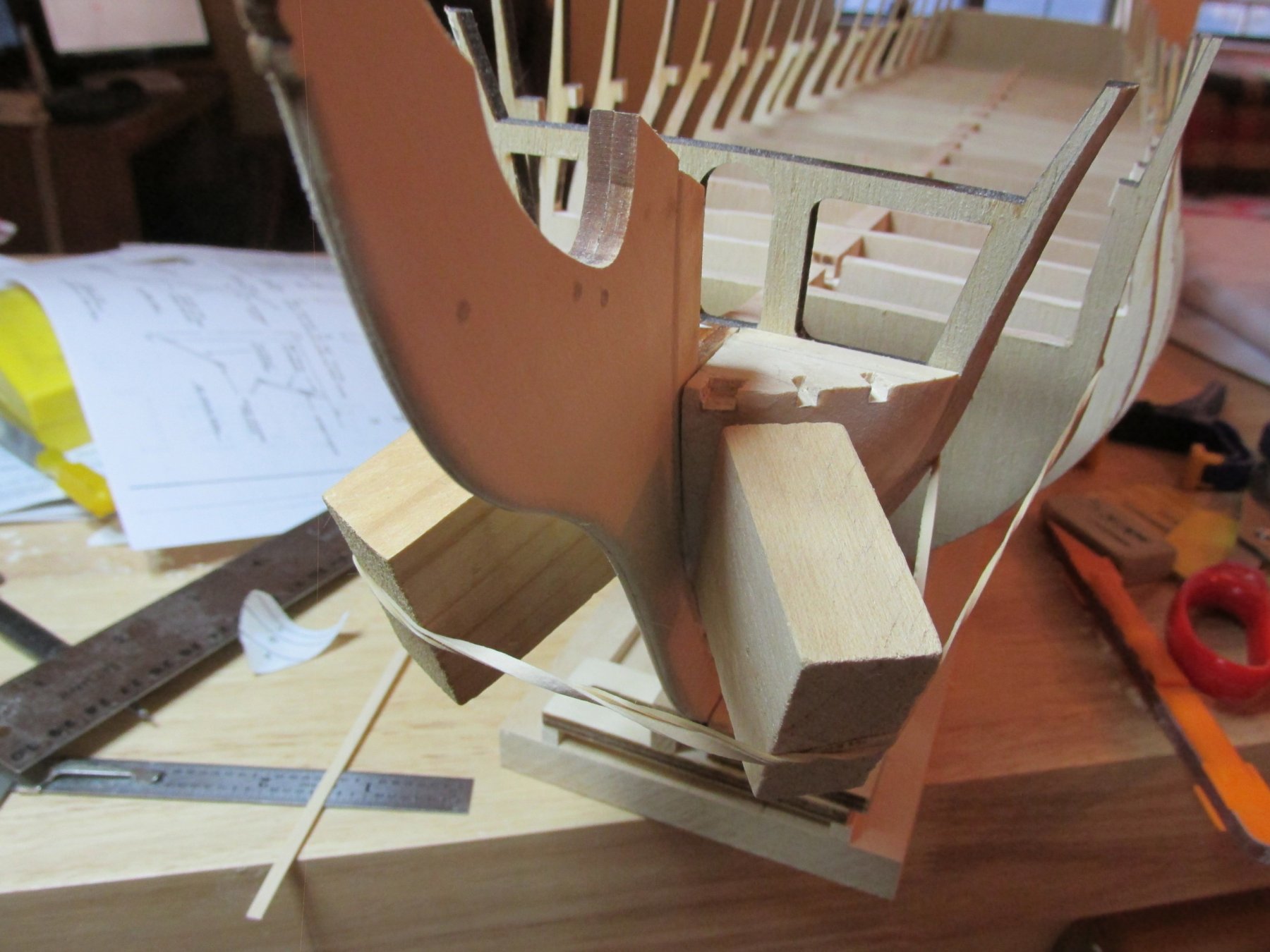
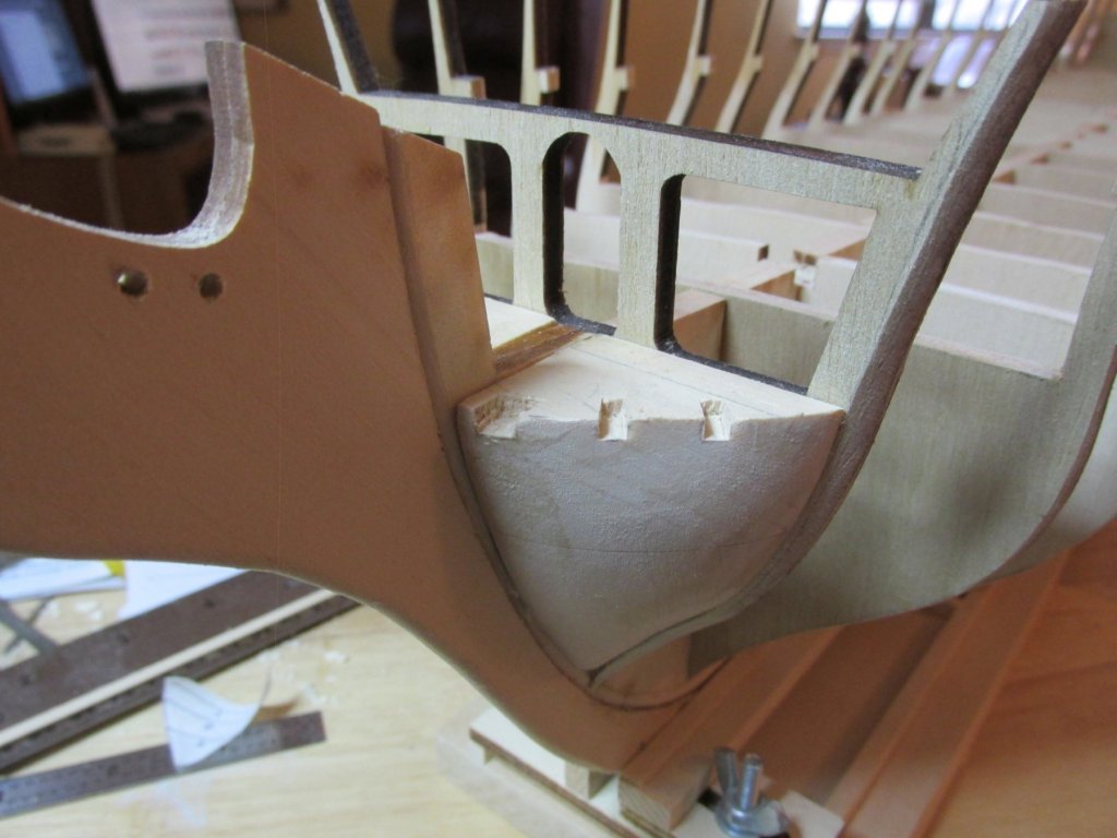
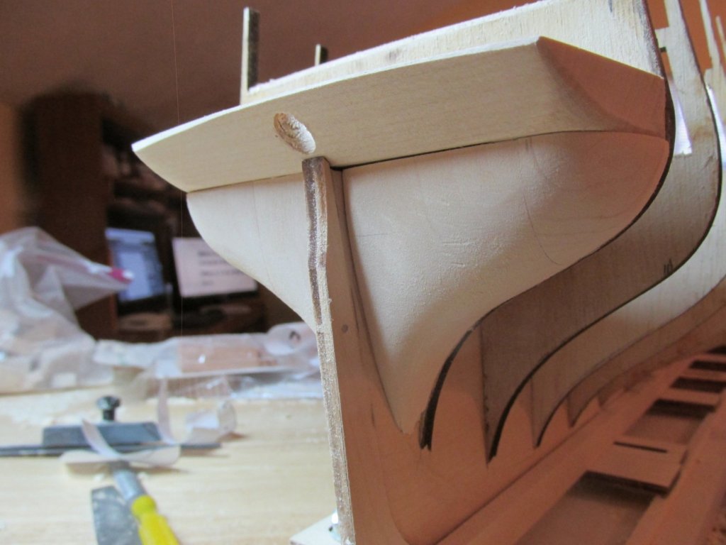
At this point, the stern counter and the filler blocks were glued into place. Any final sanding adjustments still must be made.
-
For the last bit of carving, I used the sanding disk, the rotary tool with a sanding drum, files, and sandpaper.
-
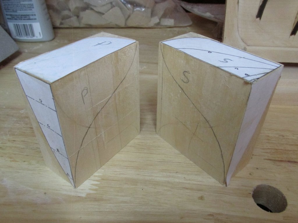
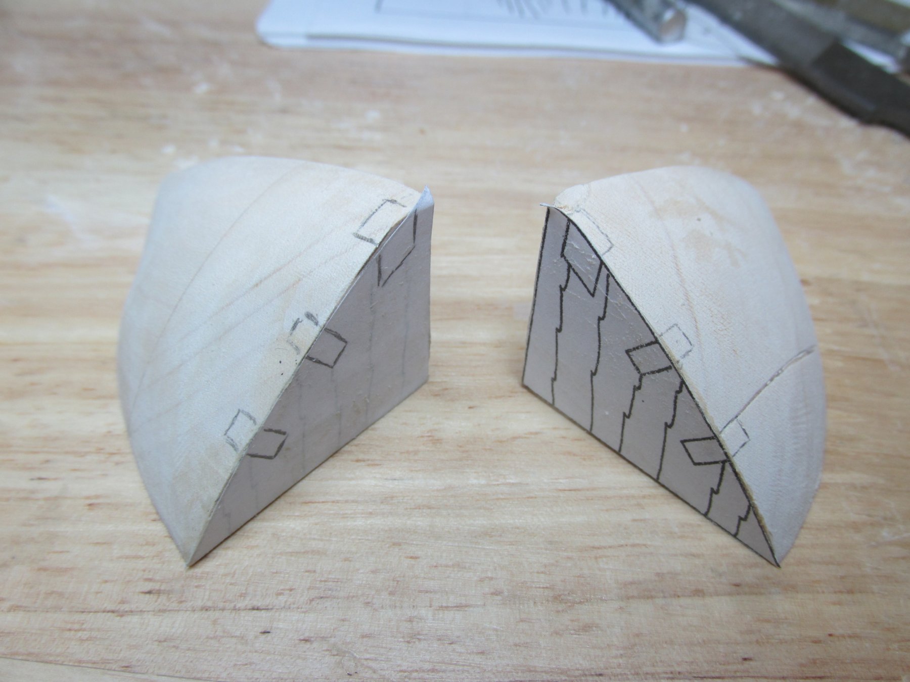
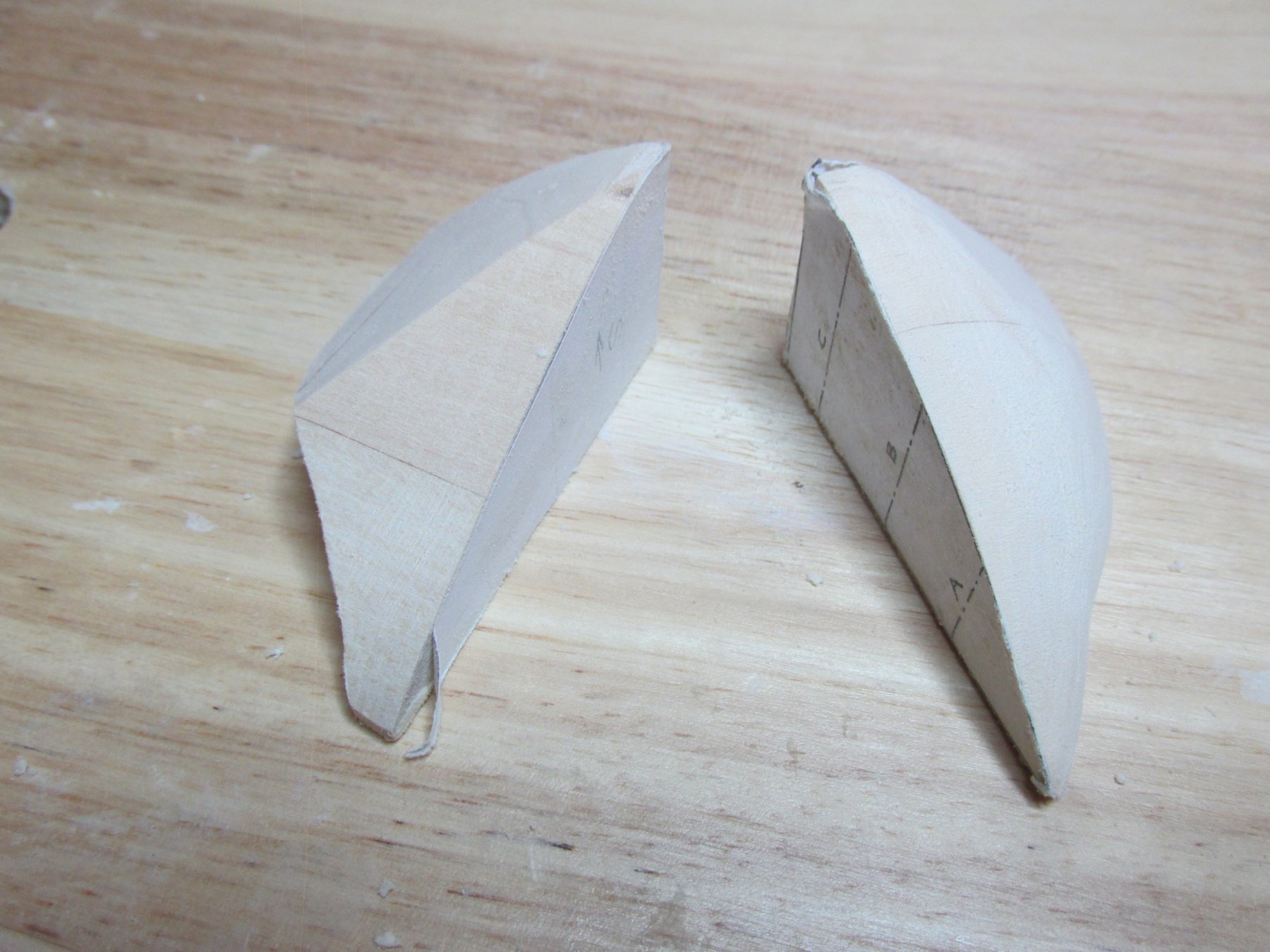
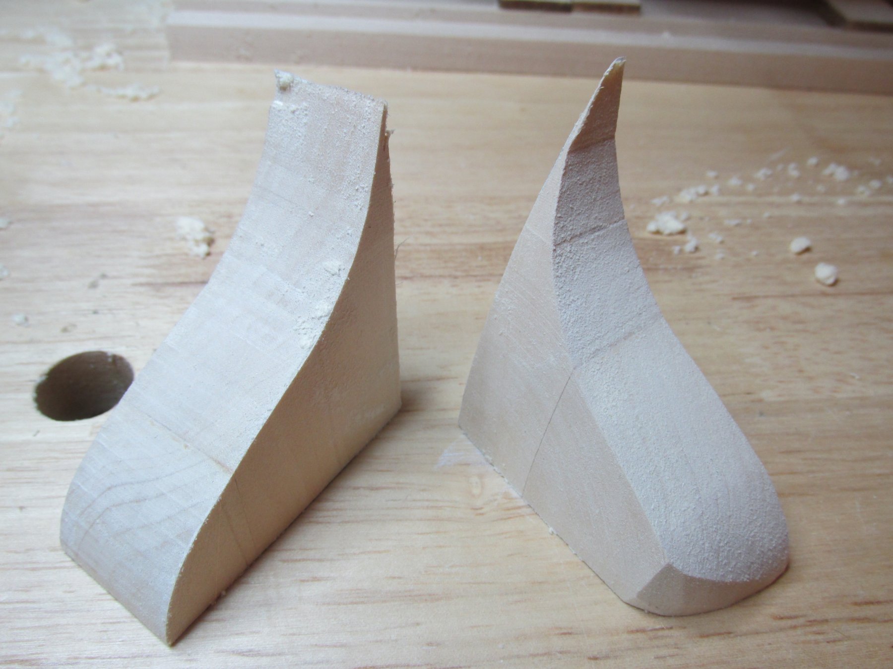
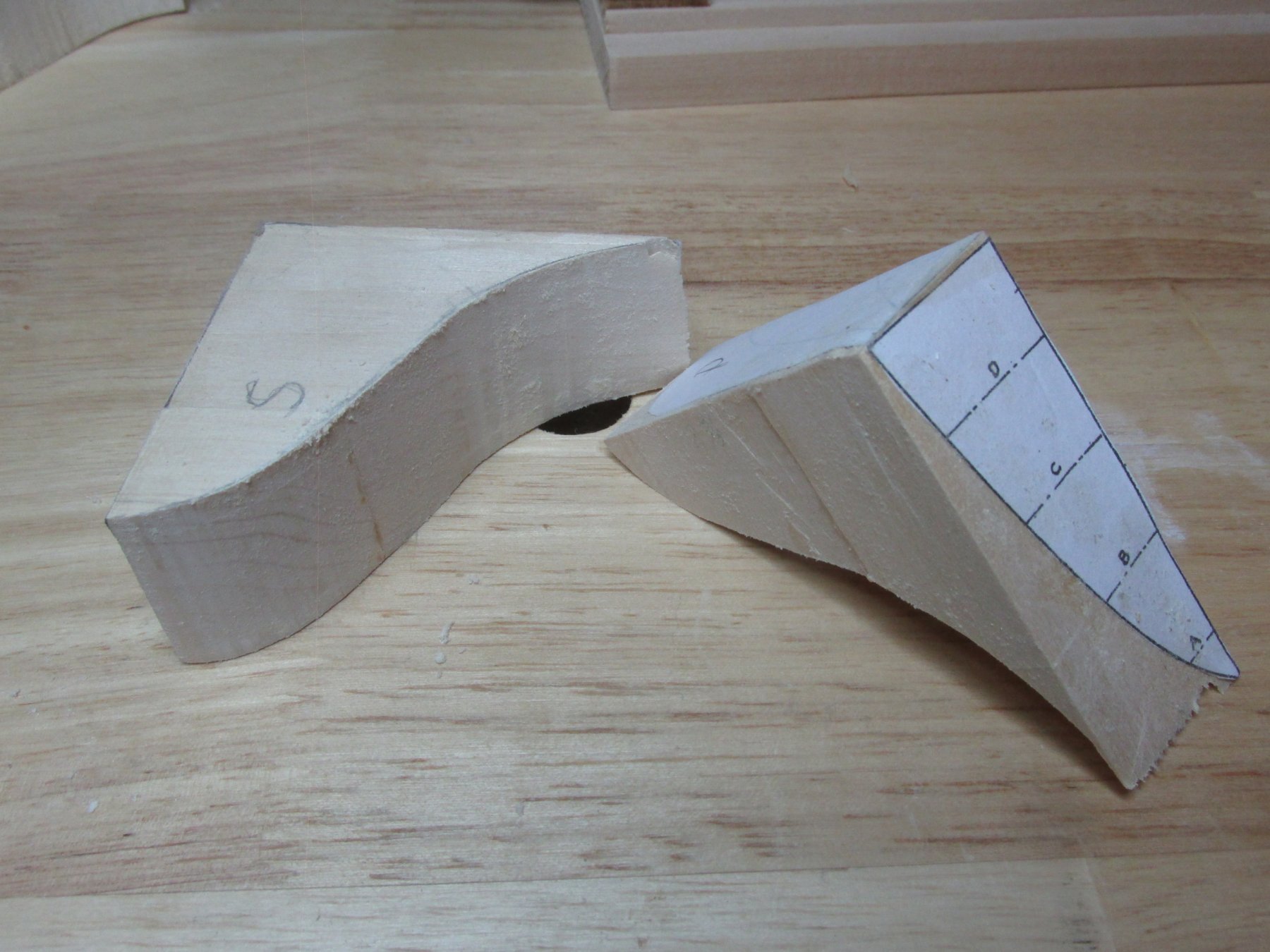
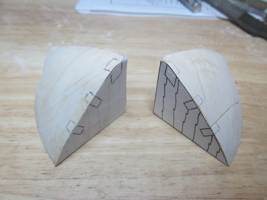
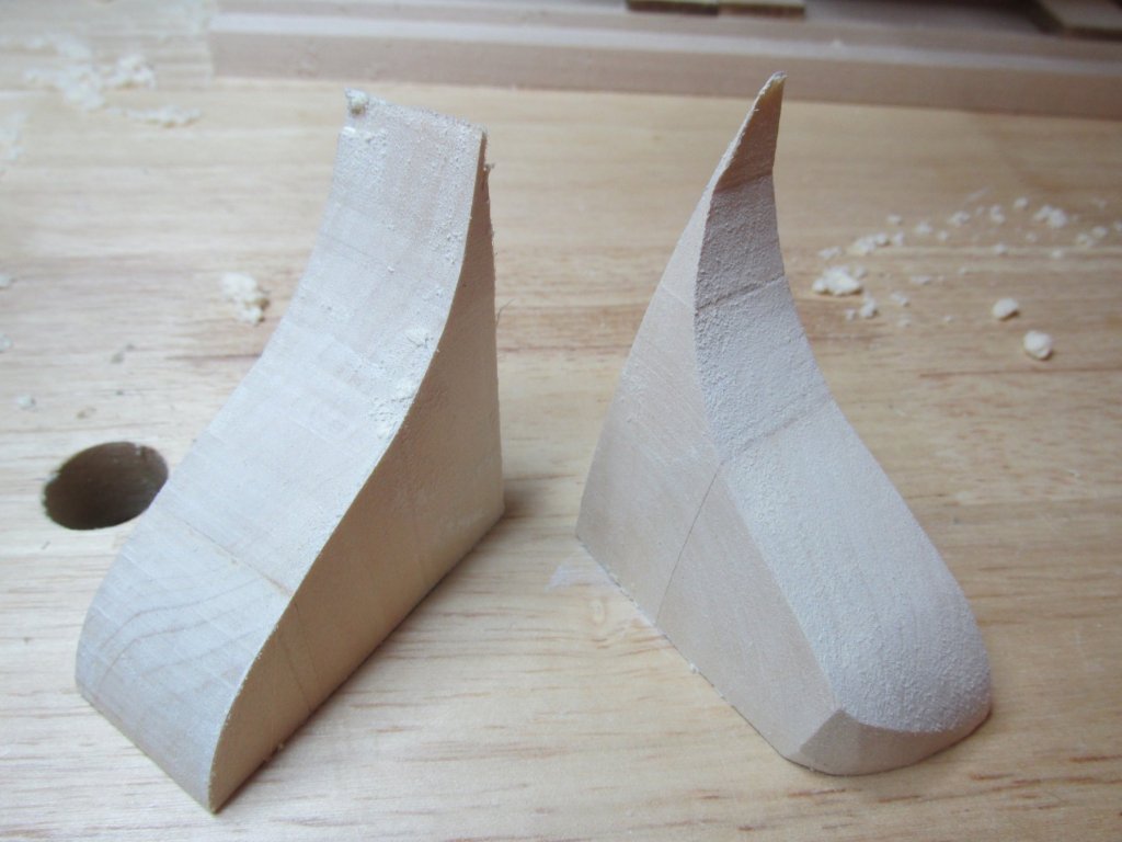
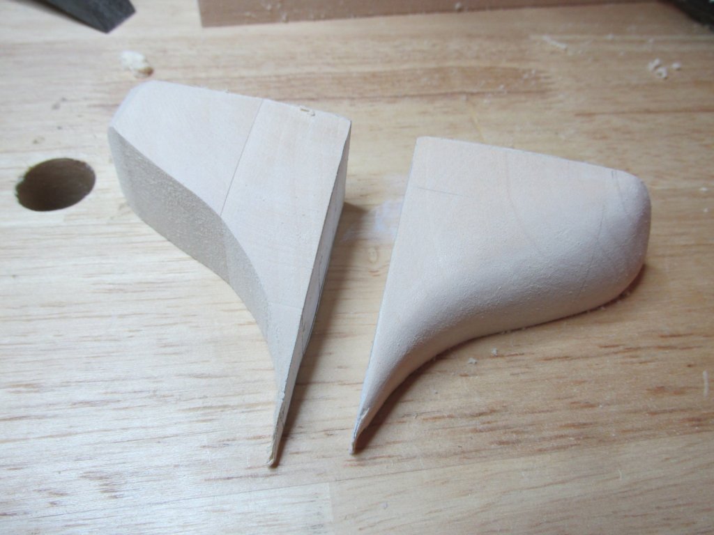
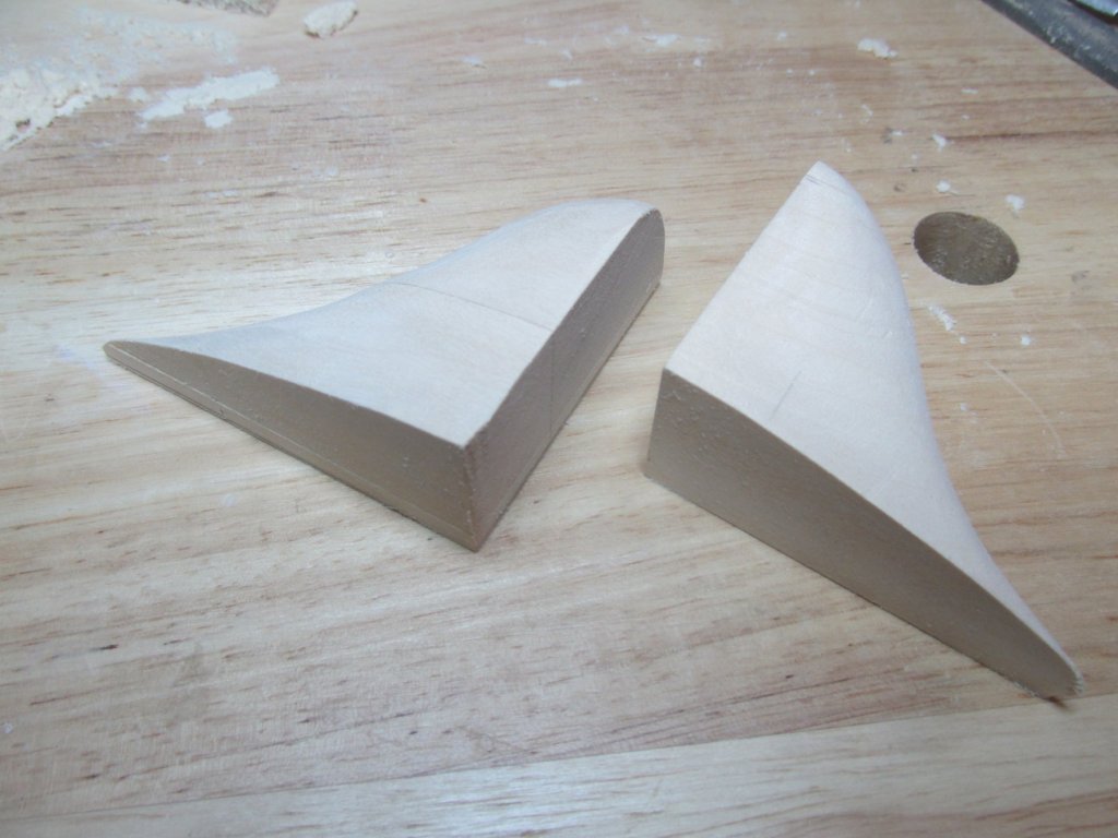
I don't know about anyone else, but I was getting an error message and could not log on for three days. Finally, somehow, everything is back. Stern Filler Blocks The stern filler blocks have a lot of curves and compound curves at that. Again, using the kit plans as templates, the appropriate template was rubber cemented to the appropriate sides of the raw basswood blocks. Using my vintage Dremel scroll saw of almost 40 yrs. old, the S-curve cuts were made. To make those cuts, my saw took about ten minutes each block. I don’t know if it was the thickness of the blocks, the fact basswood was being cut, the saw itself, or all of the above, but it got done. For those of you who are interested, the saw is a Cat. 572, Deluxe Moto-Shop 15”. The picture I got off the internet shown below, is a good representation of mine. I was just too lazy to set up a shot to get a portrait of mine.