JSGerson
-
Posts
2,614 -
Joined
-
Last visited
Content Type
Profiles
Forums
Gallery
Events
Everything posted by JSGerson
-
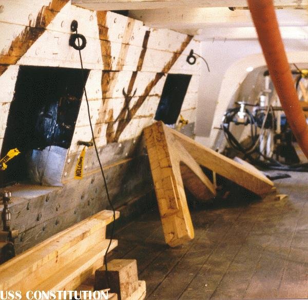
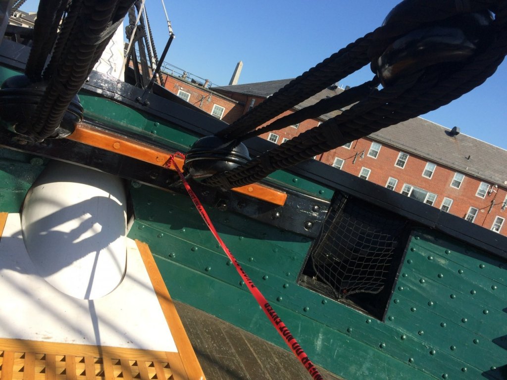
 I finally got a phone reply from the USS Constitution Public Historian to my query about the gun port netting yesterday. (he was out of town for a week). He confirmed the netting is a modern safety feature, so scratch that detail.
 -
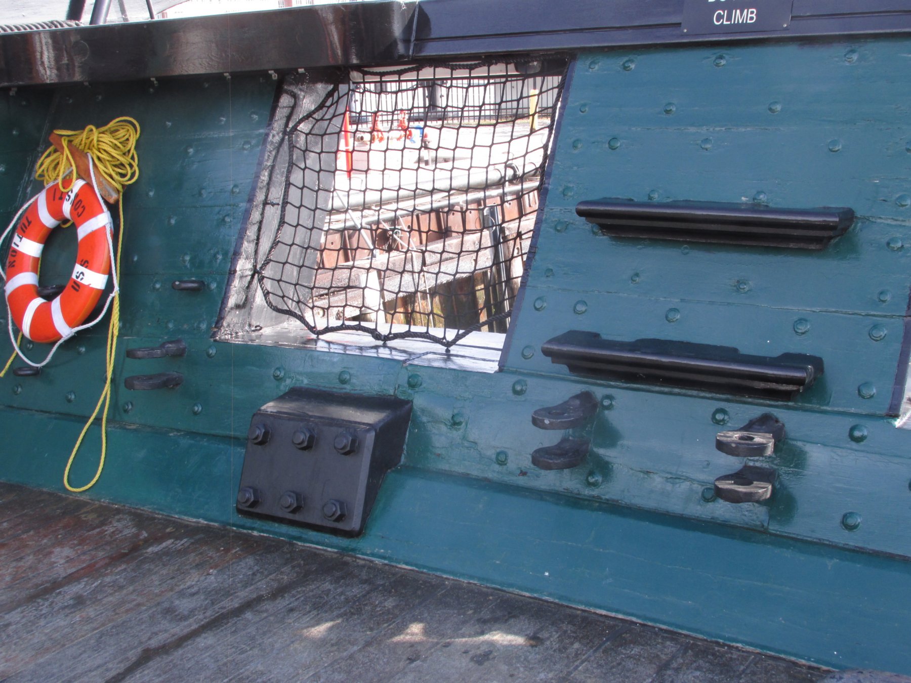
I've been trying to get a response from the USS Constitution Museum's website and Public Historian (or anyone) about the gun port netting. All I get is silence. Was it added as a modern safety devise like the sprinkler systems, lighting, etc. or is it part of the ship's fittings? In other words, do I make it part of my model or not?
Thanks
Jonathan
-
I knew that 8-)
-
Captain Steve - Who is UTS?
-
It was pointed out to me that the gun port netting may be a modern safety feature like the sprinklers or electrical lighting. If it is, then That would be the reason I've haven't seen it modeled before. Does anyone know? Thanks
-
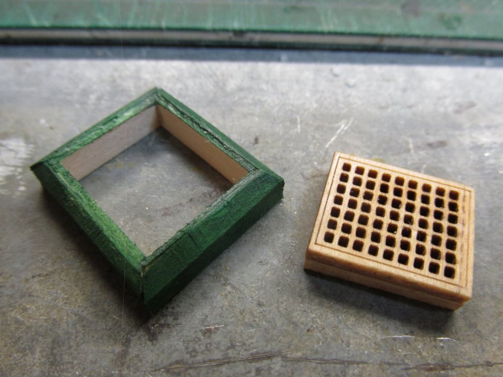
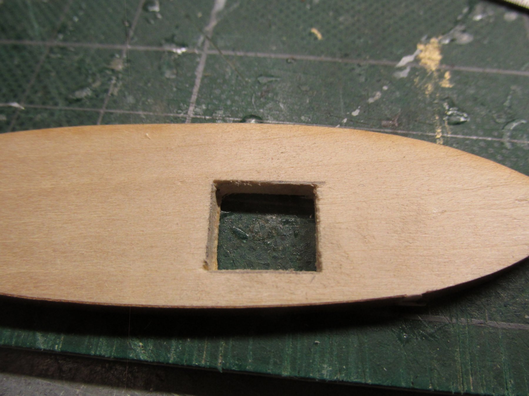
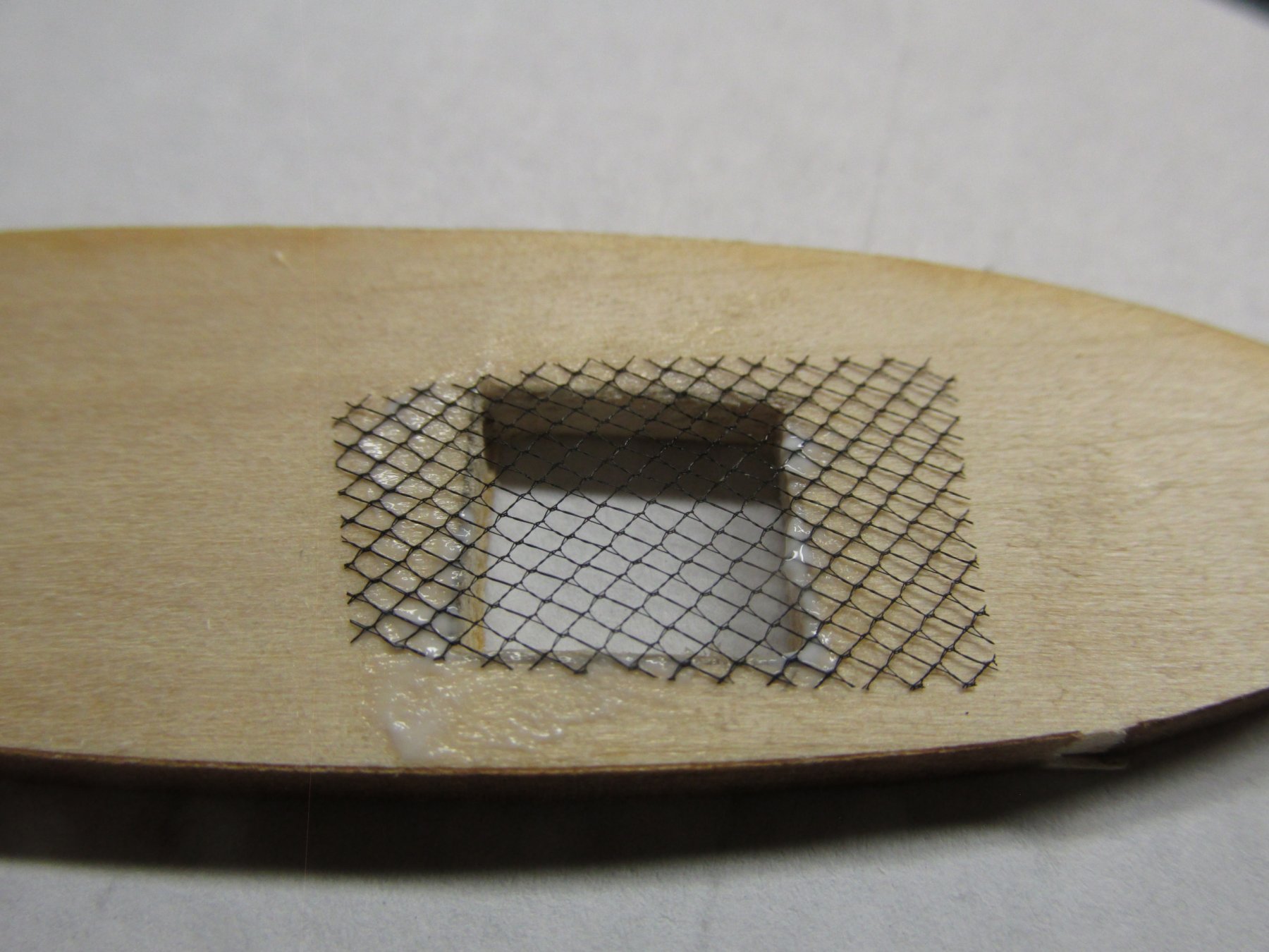
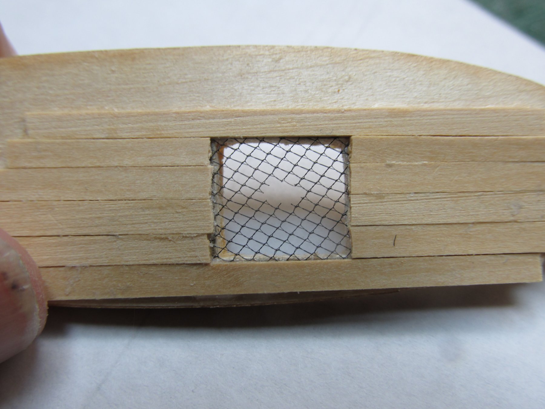
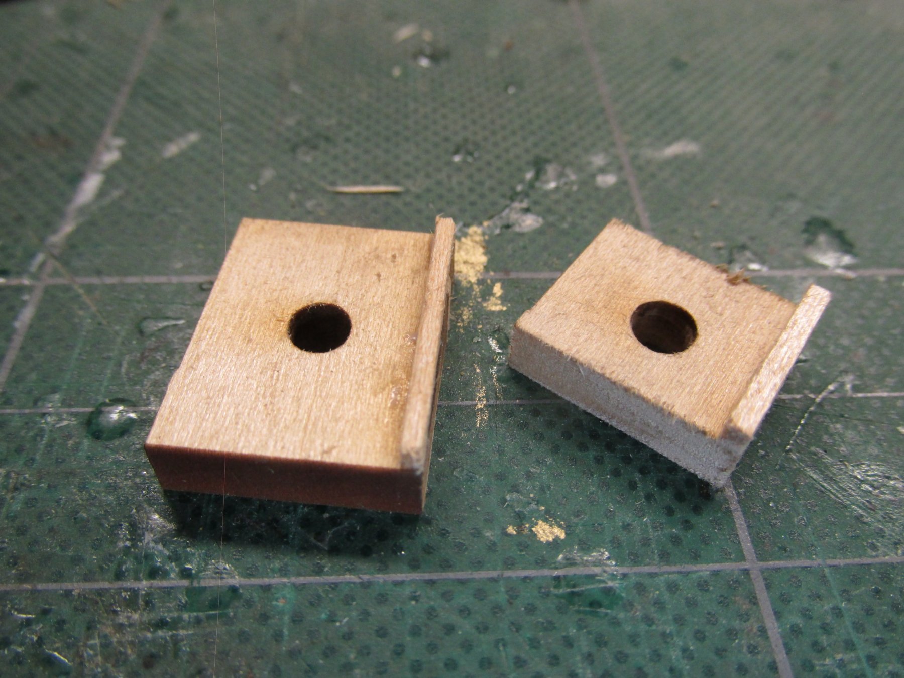
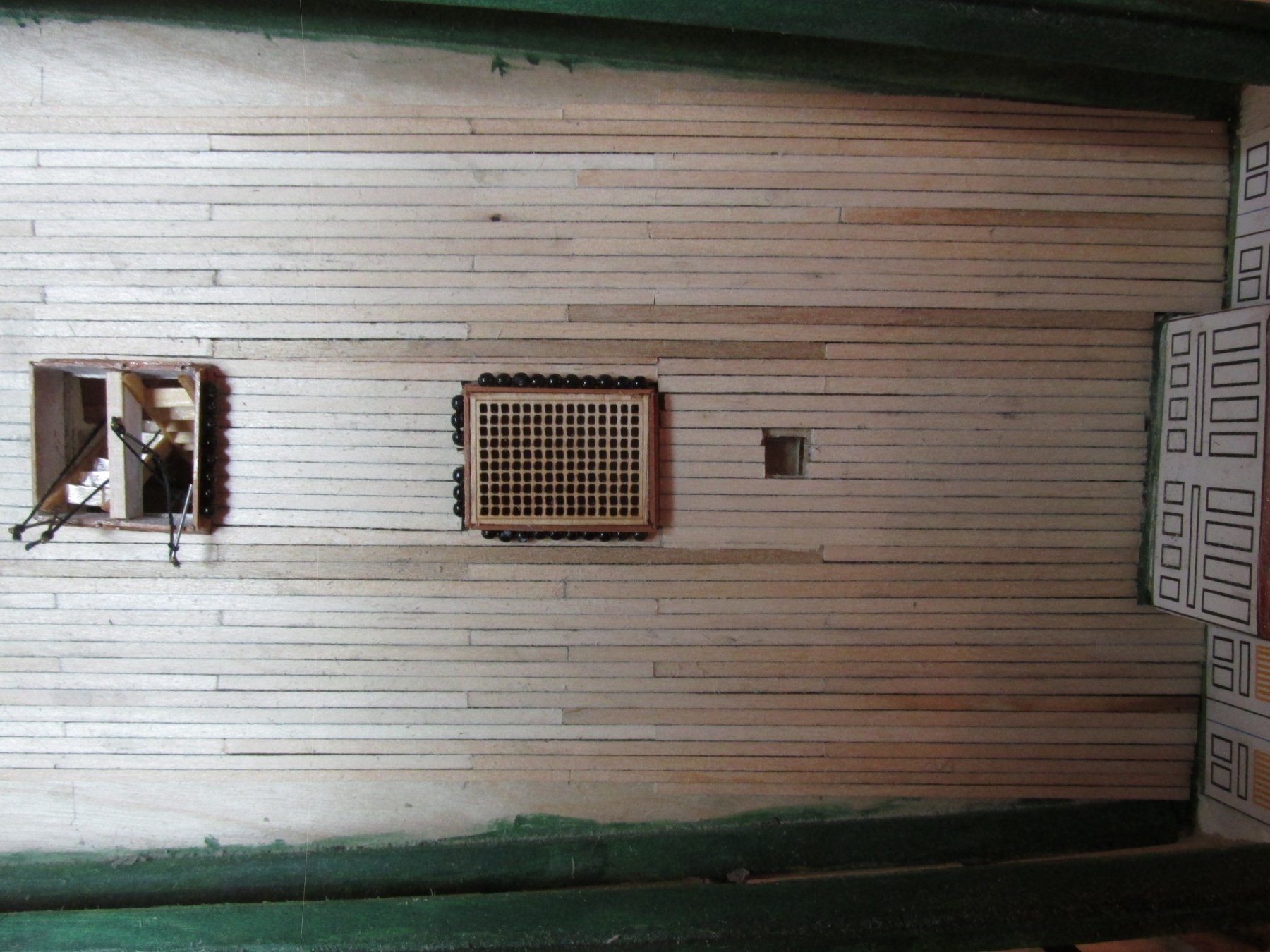
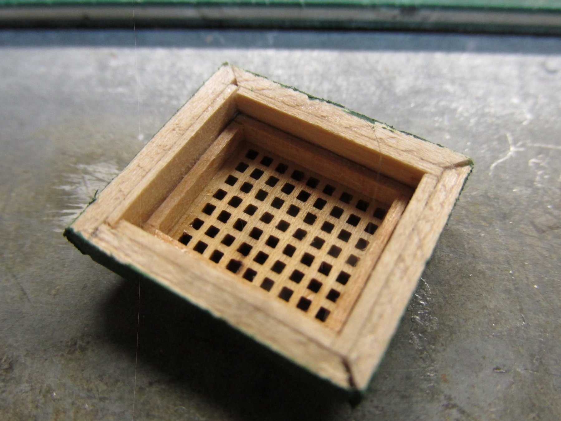
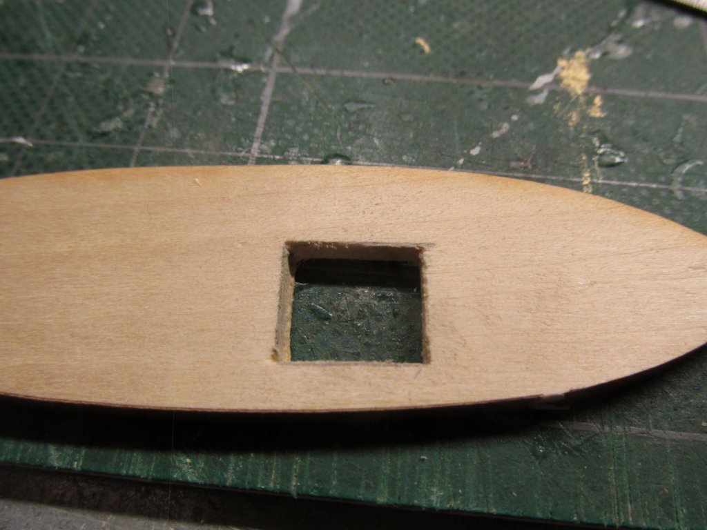
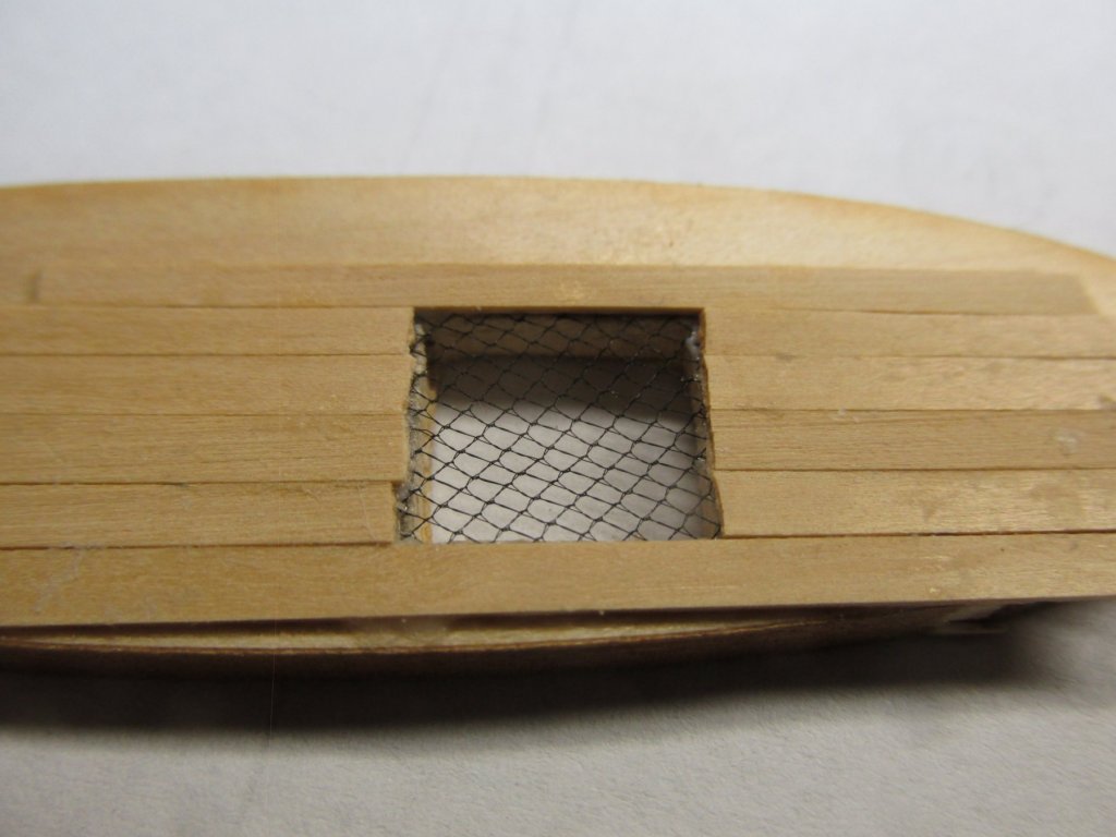
Because the kit does not supply planking for the gun deck, and I’m trying to save a few bucks, I purchased a 1/8” x 4” x 24” piece of basswood instead of buying precut strips. Using my Byrnes saw, I plan to slice the wood into 1/8” x 3/64”. Other build logs I seen have indicated 1/8” x 1/32” and 1/8” x 1/16”, so I’m in the ball park. Another thing I’ve noticed is just about nobody has incorporated the netting inside the gun port openings (both decks); I assume for its delicacy and difficulty of fabrication and installation. I may have a simple solution for that. My first try at a proof of concept seems to have worked. Using a piece of laser cut scrap wood from the ship’s boats, I cut out an opening to represent the gun port. Then with a very thin layer of PVC glue, I glued a piece of black tulle over the “gun port” opening. Tulle is a sheer (often stiffened silk, rayon, or nylon) net used chiefly for veils. I had bought some when I made my Rattlesnake. I got a lifetime supply in both black and white colors for $0.30 Then I planked it as I would the bulwarks. Because this was a proof of concept, I wasn’t too concerned with the squareness of the edges at the port opening, but this will be a precise operation when done for real because there will no opportunity to square up the edges with a file as the opening will be “closed” with the net. Finally, an opening was made in the net for the gun barrel by cutting the central portion with a fine sewing scissors. I thought about using a hot metal rod to melt a round opening but discarded that idea as too imprecise and very prone to error with one false hand tremor. The outside hull would be planked as you normally would. On the actual model, the interior of the port openings would have to be painted black prior to the net being installed. The bulwarks are to be painted white, so care must be taken not to get any white paint where its not intended to be.


-
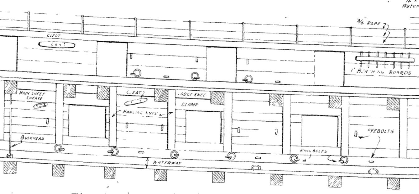
Gun Deck Bulwarks I have a US Navy plan titled Gun Deck & Inside of Bulwarks by G.F. Campbell with no identifying number or date. Based on the drawing letter style, I would guess it’s from the 1927 restoration. I believe this is when the waist was incorrectly covered over by the bulwarks. It shows it took 3 bulwark planks to extend from the spar deck gun port sill to its header. At the same time, it took four planks to do the same on the gun deck. Today, based on photographs, they are both the same at four planks which is also reflected in the kit plans. The kit calls for 3/64” thick spar deck bulwark planks. Per direct measurement from the plans (as it does not specify), the planks are 3/32” wide, thus 3/32” wide x 3/64” thick.


-
Dave, progress ye.s. Good progress?....well I don't know, I'm slow, but thanks for confidence vote. Jon
-
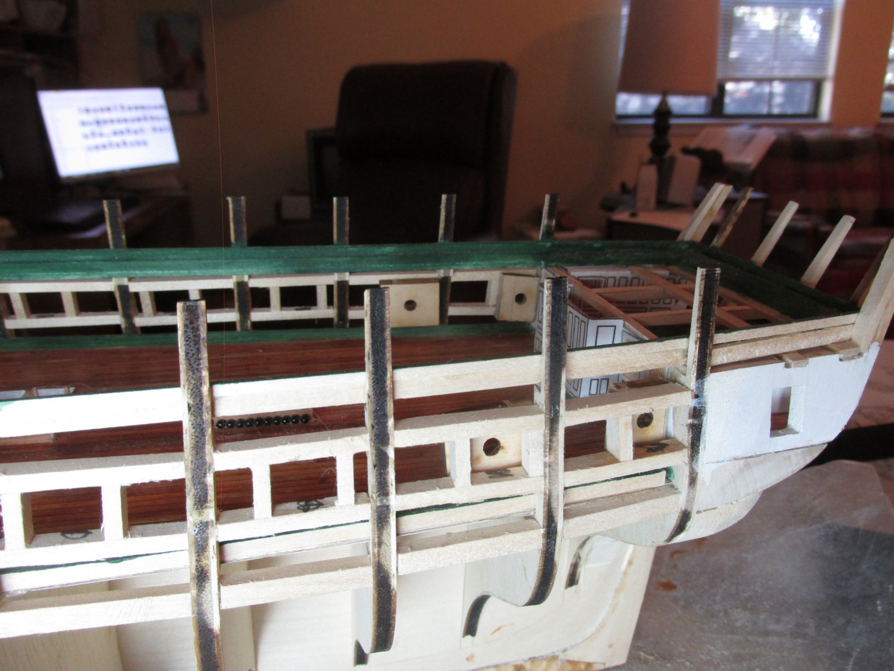
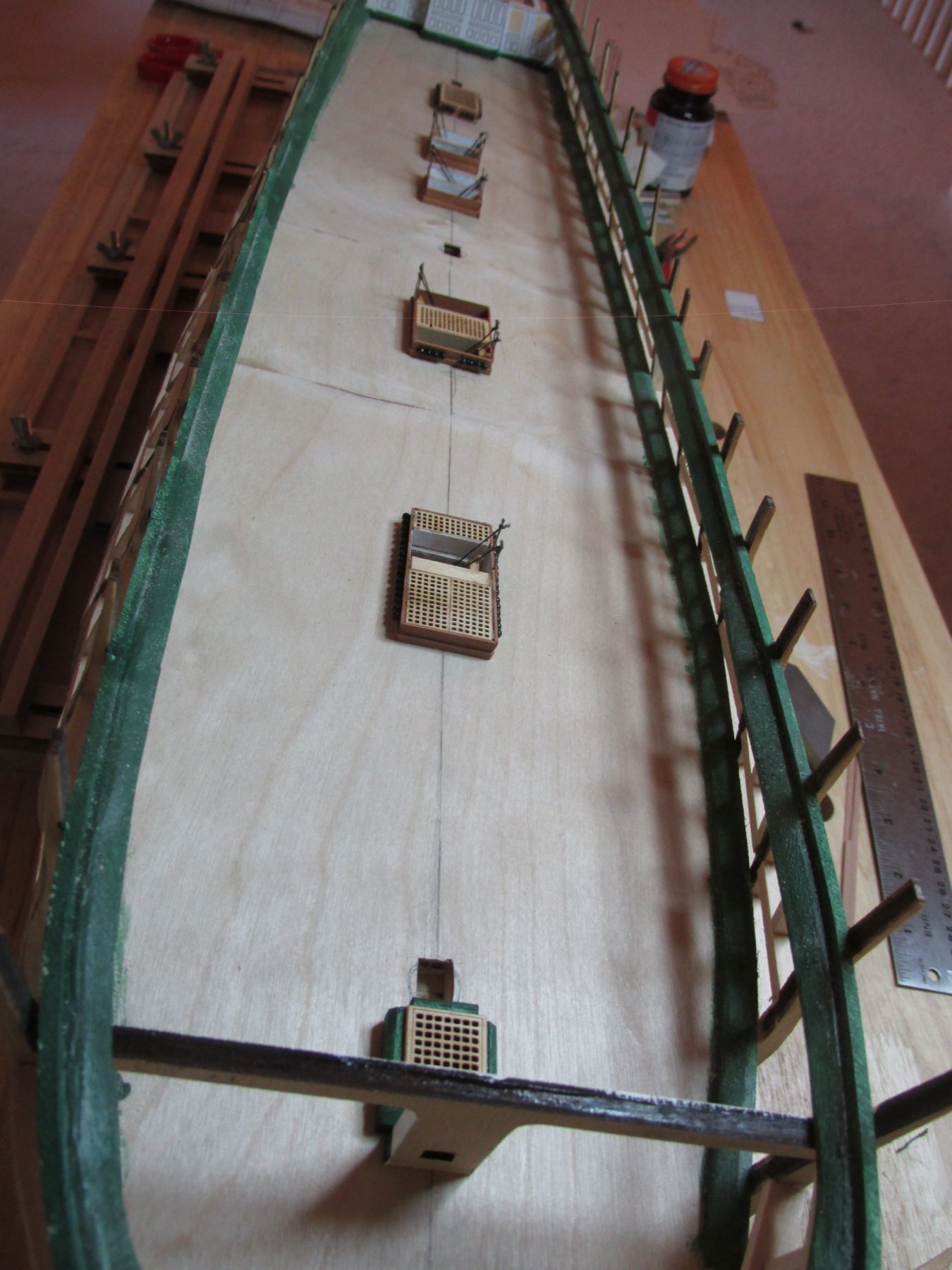
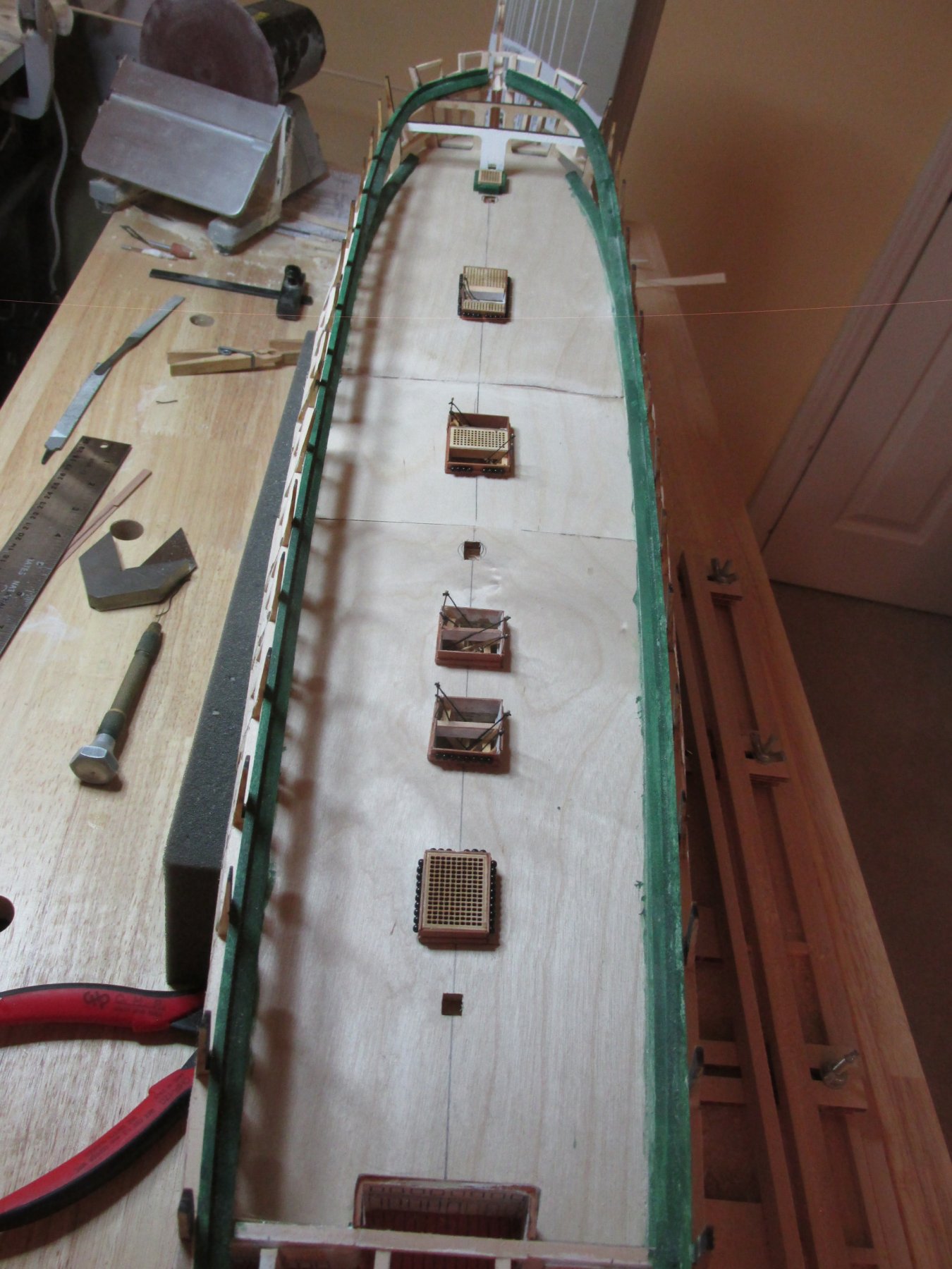
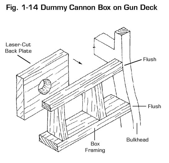
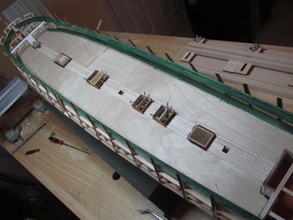
The next set of gun ports aft of the bow and the last two gun ports forward of the quarter galley will have the dummy guns because they won’t be seen (hopefully) through the opens in spar deck. All these ports will have their lids closed so that the gun boxes won’t be visible. The kit instructions show the box piece being added to the framework and states specifically that they should be mounted vertically. The diagram shows the gun port wall back edges perfectly vertical, however mine are like the spar deck diagram. In order to make them vertical, I added a small piece of wood to the base of the box. I also had to trim the far aft pair of boxes because they butted up against the captain’s cabin which wasn’t part of the kit’s plans. Those with sharp eyes will notice that I have marked the port openings with black chalk, so I don’t stick the cannons in the wrong openings or plank over them.


-
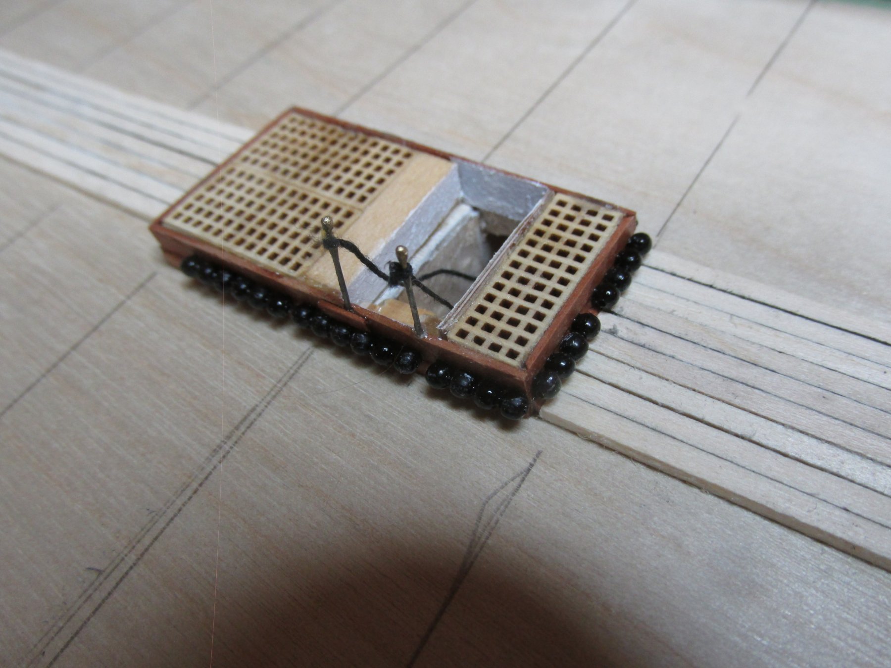
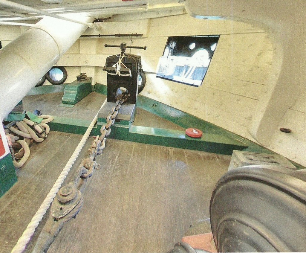
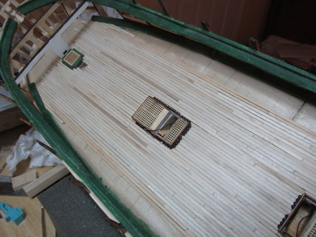
Gun Port Boxes for Dummy Cannons Another week, another hurricane, OK, tropical storm (Michael). I got wind and rain, but luckily no damage. As noted way earlier in my log, I plan to use some dummy guns on the gun deck. The first pair of gun ports in the bow won’t have any guns at all, as there is no room for them to operate. They may be some confusion when looking at the ship from the outside, because it appears there are guns with a tampion in their barrels poking out through the gun port lids. The tampions are there only to plug the muzzle openings created by the lids. You can see one lying on the green floor beam in the first image.

-
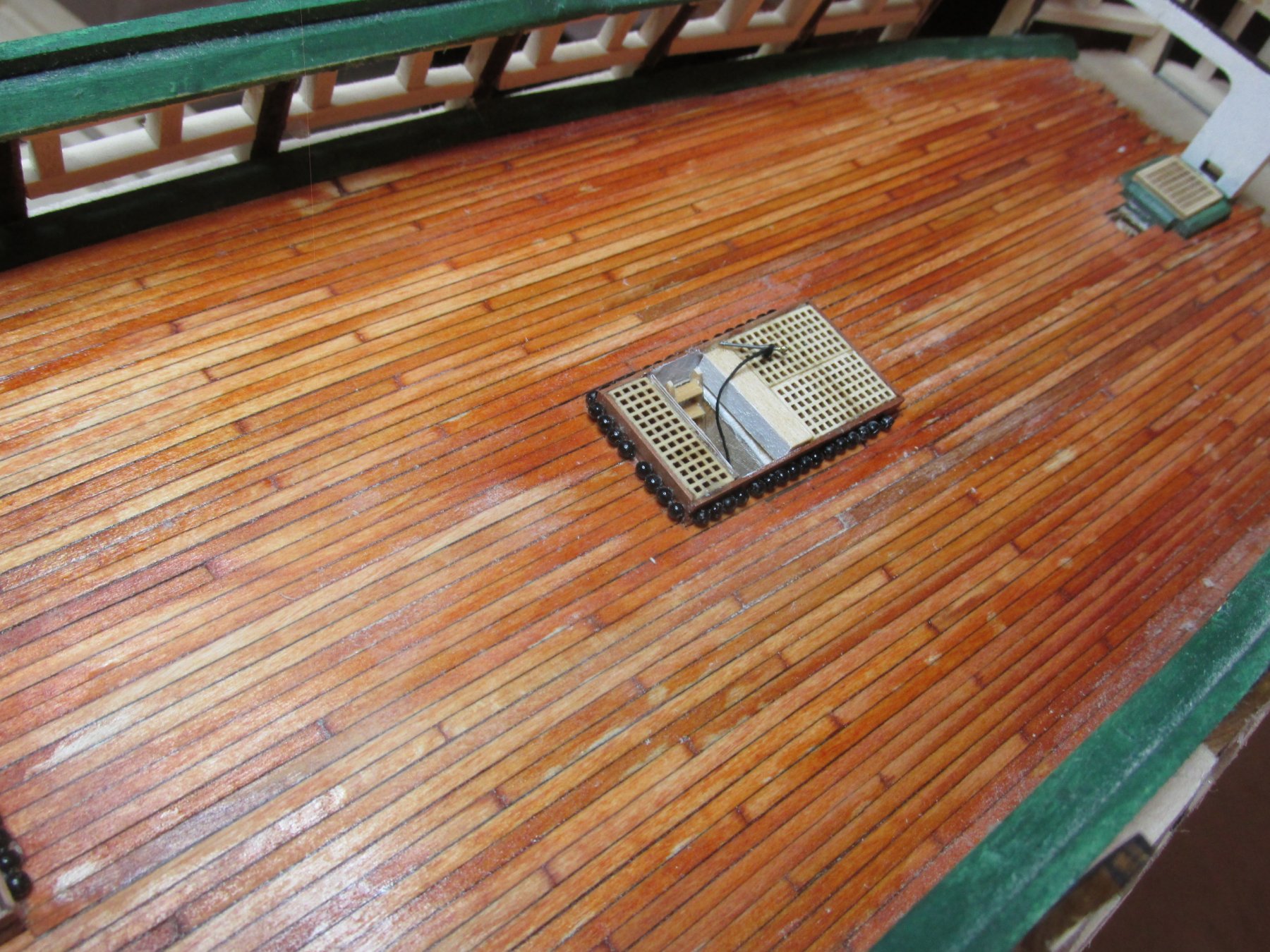
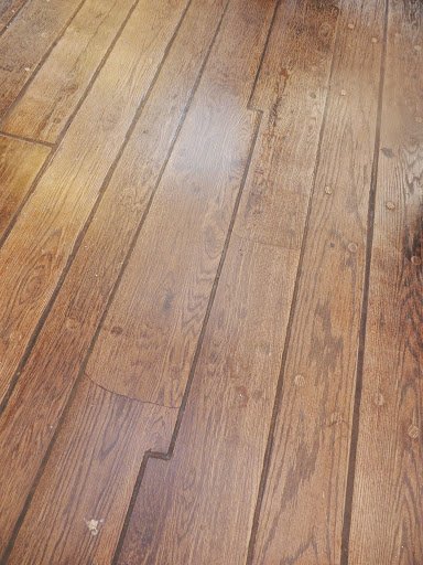
My first attempt, if you remember, was the decking in the captain cabin which I printed on paper and glued to the plywood. Not very realistic but then most viewers won’t even see the that interior. This attempt was made using Minwax Gunstock 231 as the first coat. This has a rosy hue to it. Then, I applied Minwax Golden Pecan 245 to tone down the red and add some depth to the stain. Finally, I added Minwax Polycrylic Clear Satin as the sealer. I got a good simulation of planking, but maybe just a smidge too much red. As it turned out, the color did match to captain cabin. Once more, the viewer will have limited access and dim lighting conditions as well. In any event, it is what it is. The ladder stanchions have not been repaired yet, and I might delay the repair till the last possible moment so that I won’t damage them any further.

-
Gun Deck Stained & Sealed I tried to stain the Gun Deck as close to the color of the actual ship as I could. I have a number of images and each one is slightly different than the next due to the various lighting conditions of artificial lighting and indirect daylight among other things. One of those images is shown below.
-
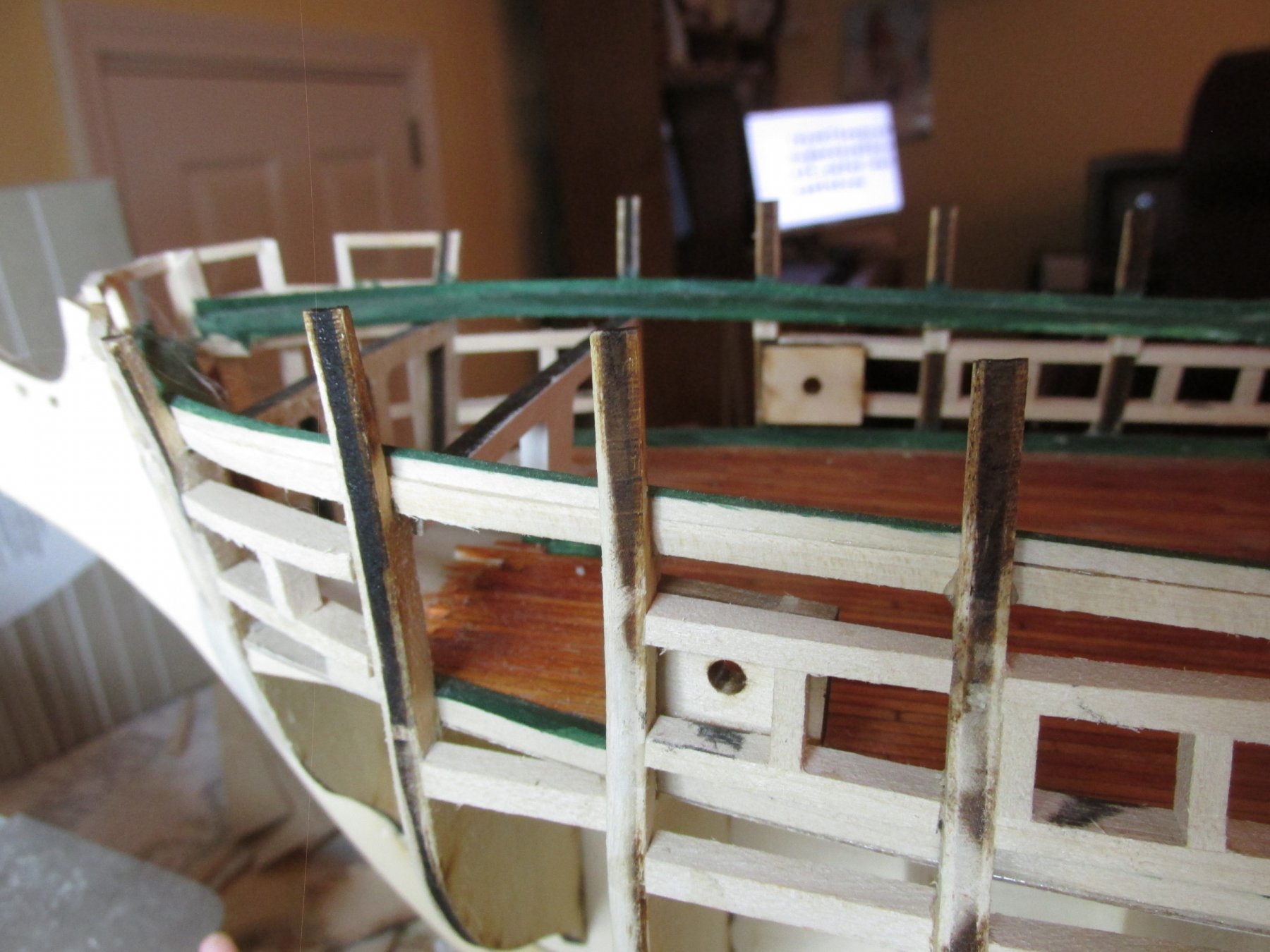
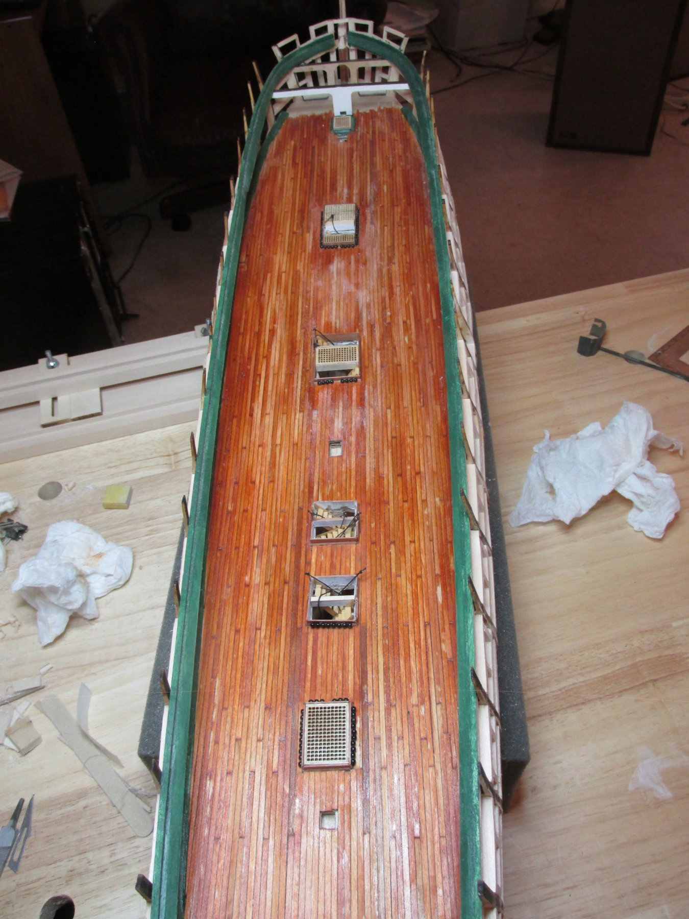
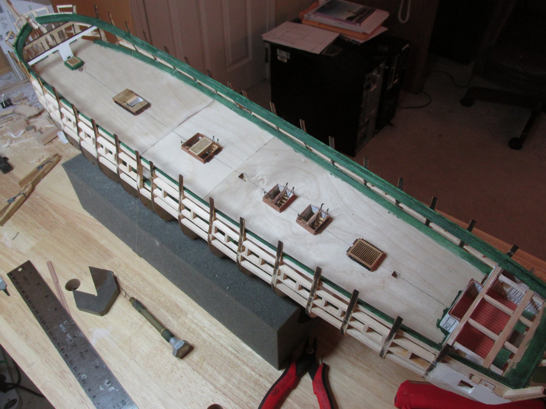
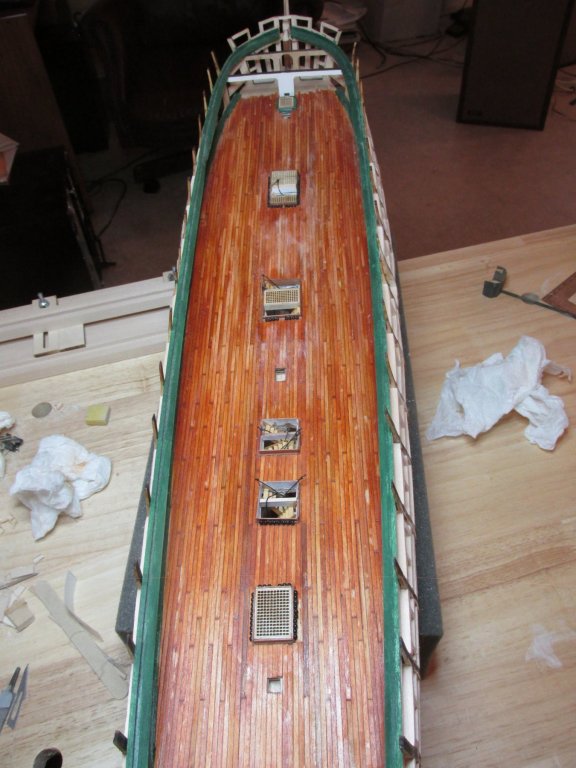
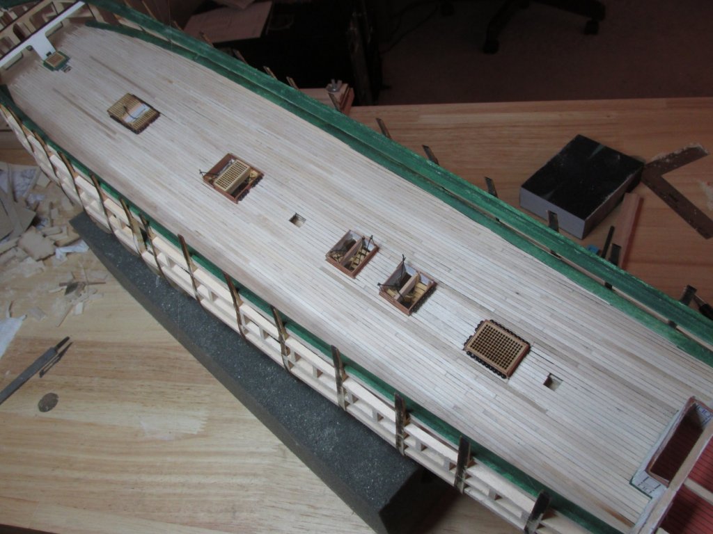
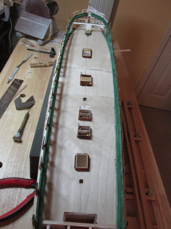
Wow, a month has past by already. In between doctor’s appointments, hurricane Florence, and the what-nots, some progress has been made. I’ve completed planking the gun deck, but there is still work to be done on it before I can move on. The deck required about 45 sticks of 3/32” x 1/16” x 24” basswood. Surprisingly, I had very little waste, about 6” combined. As you will see from the images below, I managed to knock down almost every ladder stanchion so those will have to be repaired. The planks still need more sanding and then will need to be stained and sealed.

-
I don't know much about fishing line. You wouldn't happen to know, or point me in the direction of, the diameters of those lines you use? As you know, in our world of model building, scale is everything. Fishing line is about strength and the nomenclature of the line depends on what type of fishing is involved. Somewhere, somebody must have made a conversion chart of line strength to diameter. Even sewing thread is marked differently even among themselves depending on its application It's very confusing. I just want to know what the thickness is. Jon
- 742 replies
-
- 3
-

-
- constitution
- frigate
- (and 1 more)
-
Very neat and pretty. Out of curiosity, what miniature rope are you using. Typically I use Chuck's rope from Syren Ship Model Company, the kit's rope, and sewing thread but usually have a problem with very fine line for example flag halyards or ratlines. You have an advantage with your slightly larger scale build which makes even normal sewing thread seem relatively fine. The lines shown on your bowsprit are beautifully delicate. What did you use? Jon
- 742 replies
-
- 3
-
-
- constitution
- frigate
- (and 1 more)
-
I feel very relieved you were spared. Living in the western part of South Carolina, I too was lucky; I barely even recognized that there was a storm going on to the east of me. I hope the relief effort for the rest of your community moves swiftly and all will be back to normal soon. Looking forward to your progress pictures. Jon
- 742 replies
-
- 7
-
-
- constitution
- frigate
- (and 1 more)
-
I'm just a couple a three hour hours away from you, and you would think I was on the other side of the country; blue sky, puffy white clouds, with just a few gusts of wind. I'll probably have more weather this weekend. Take care and keep safe. Jon
- 742 replies
-
- 6
-
-
- constitution
- frigate
- (and 1 more)
-
Thanks Ken for the "look in." Your build will be one of the main build logs I'll be using as a guide as my build syncs up with yours.
-
Well, that sucks. I was looking forward to more posts. I assume it was the transom that took its toll on you...plus the lights...plus the 1812 modifications...plus... plus... plus... Sorry to see it end this way. I look forward to your next endeavor. Jon
-
The way I belayed the preventer lines into deck eye bolts on my Rattlesnake was to pre-drill the eye bolt holes early on. When the time came, the eye bolts were then rigged to the preventer lines. The whole rigged eye bolt was then inserted into the pre-drilled deck hole. This eliminated trying to thread through the eye bolt and seizing the lines while the eye bolt was attached to the deck. I know it's too late now, but maybe this tip will help someone else or you on a later build. Nice work on the ratlines by the way. Jon
- 742 replies
-
- 4
-
-
- constitution
- frigate
- (and 1 more)
-
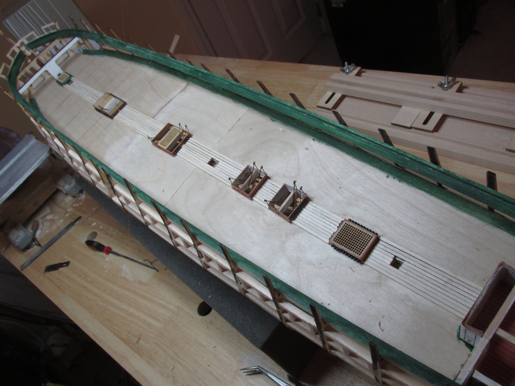
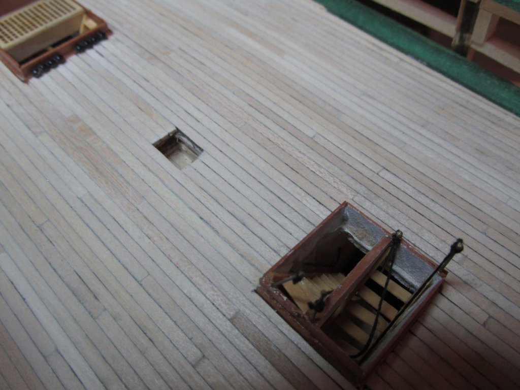
Gun Deck Planking Now that the gun deck hatches and ladders have been installed, it was time to install the gun deck planking. After a little research, I’ve determined that the deck plank length vary from about 16’ – 30’. The distance between the various hatchways and scuttles is well within those limits. Therefore, there would be no planking joints when planking in those areas. Robert Hunt’s practicum also reached that conclusion although he was only dealing with the spar deck. Using artist’s charcoal, I colored just one side of each plank which worked well. I had originally thought to use CA glue to fasten down the planks, but I found the CA glue soak too quickly into the plywood subdeck. Making the glue bead thicker just made it messier with no time to adjust plank positions. I resorted to wood glue (Wellbond) and had no problems. I added lines perpendicular to the beam on the subdeck to represent the underlying gun deck support beams. This is where plank joints will appear and line up as necessary.

-
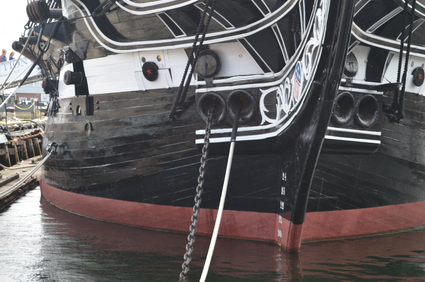
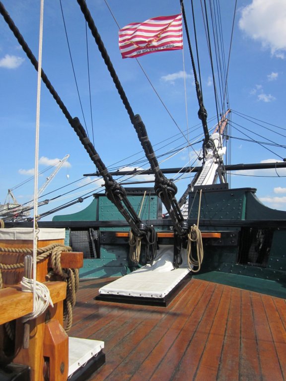
I have a question about the recent overhaul the USS Constitution just completed. I was poking around various build logs and sites looking for detail images that I could use in constructing my model of the Conny. On JerseyCity Frankie's log U.S.S. Constitution Turn Around Cruise 6/8/18, he had an image of the bow looking forward where the bowsprit starts. The structure atop of the railing which looks like a wave breaker (my term) has been removed. JerseyCity Franklie only provided the one image which leaves a lot detail to be desired.
I've included a before image and JerseyCity Franklie's "after" image.
I am curious as to why the change was made and if you could provide any more images. I would like to incorporate this latest modification into my model.
-

The origins of the topgallant rail and bulwarks on the Constituion are some time around the 1927 refit, I believe. At that time the Navy decided that the bulwarks all around the ship should be raised and to have bulwarks at the waist installed to the same height. You do not see them, obviously, in this photo but they were done completely around the ship.
I forget which year it was, but during the refit before this last one the decision was made to bring the ship more in line with her 1812 configuration. To that end, the bulwarks in the waist and the topgallant rails were again removed, as you see in your second photo. Also at this time the proper camber was built into the deck, the thick planks (or king planks) were put into the deck, and the diagonal riders were installed in the orlop.
Regards,
Henry
-
I knew the bulwarks at the waist were removed to conform more like 1812 but did not know about the top gallant rail. All the images I've seen except the second one, show the rail. Any chance getting more images without the rail?
I assume that the lines that use to go through the holes at the top of the rail terminated at the belay pins below it; so that now they go directly to the belay pins. Is that correct?
Thanks for your help.
Jon
-
-
So, as it stands, this is what 8 months of work on the hull has accomplished so far. Just cruising along 8-)


-
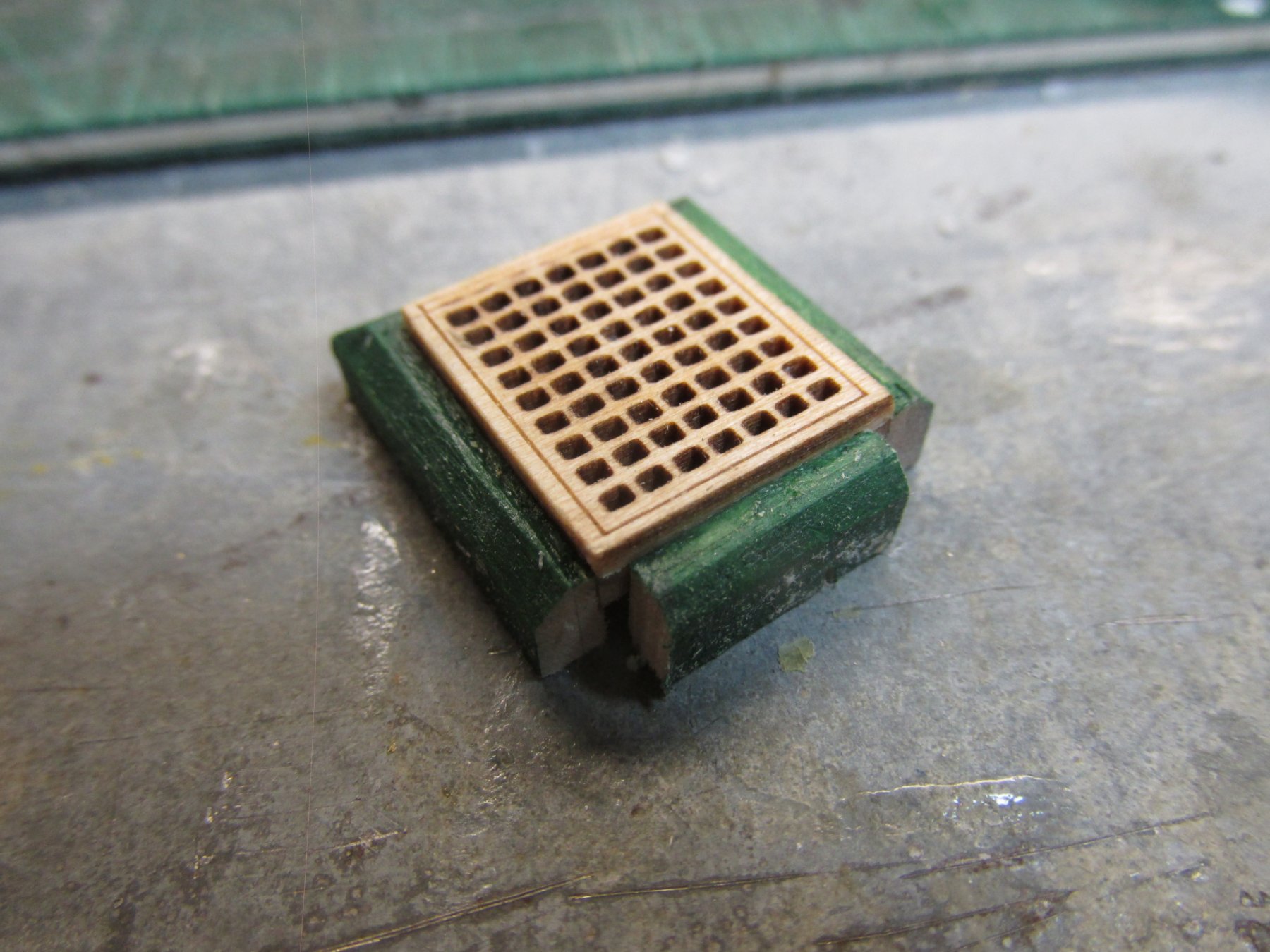
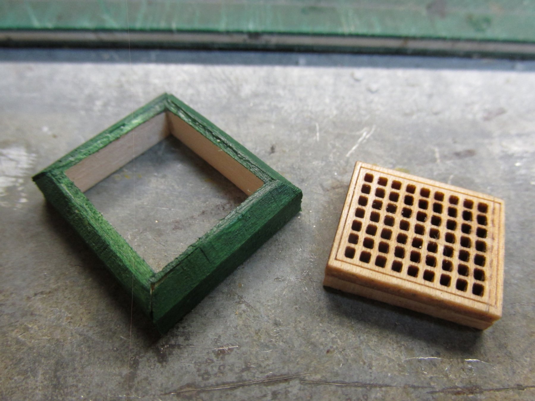
At this point I thought I was done, but then realized I needed to do one more thing. If you look at the picture of the actual scuttle (above), you will notice there is a post on either side of the scuttle where vertical posts are. They notched into the scuttle frame Using my Byrne’s saw, I very delicately cut out the notches and painted them. The bow sprint support was painted, and the scuttle was set into place. The kit’s bow sprit support brace is the furthest forward I plan to add details on the gun deck.

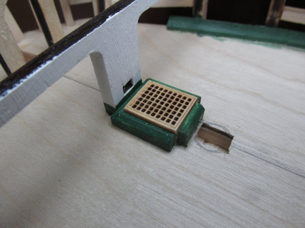
-
The frame was then painted green. I’ve flipped the structure over so that you can see the underside construction.