HOLIDAY DONATION DRIVE - SUPPORT MSW - DO YOUR PART TO KEEP THIS GREAT FORUM GOING! (Only 13 donations so far - C'mon guys!)
×


JSGerson
-
Posts
2,611 -
Joined
-
Last visited
Content Type
Profiles
Forums
Gallery
Events
Everything posted by JSGerson
-
 I like the look of the exposed gun deck. It's something like I did on my Rattlesnake. I'll be following your lead for this part on my Conny build, but at 76.8 scale. That should be interesting.
- 742 replies
-
- 7
-

-
- constitution
- frigate
- (and 1 more)
-
zappto - thanks for joining the group
-
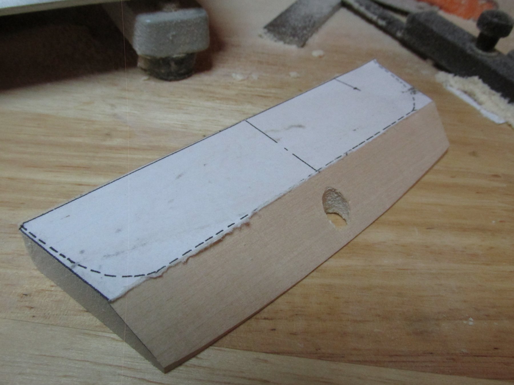
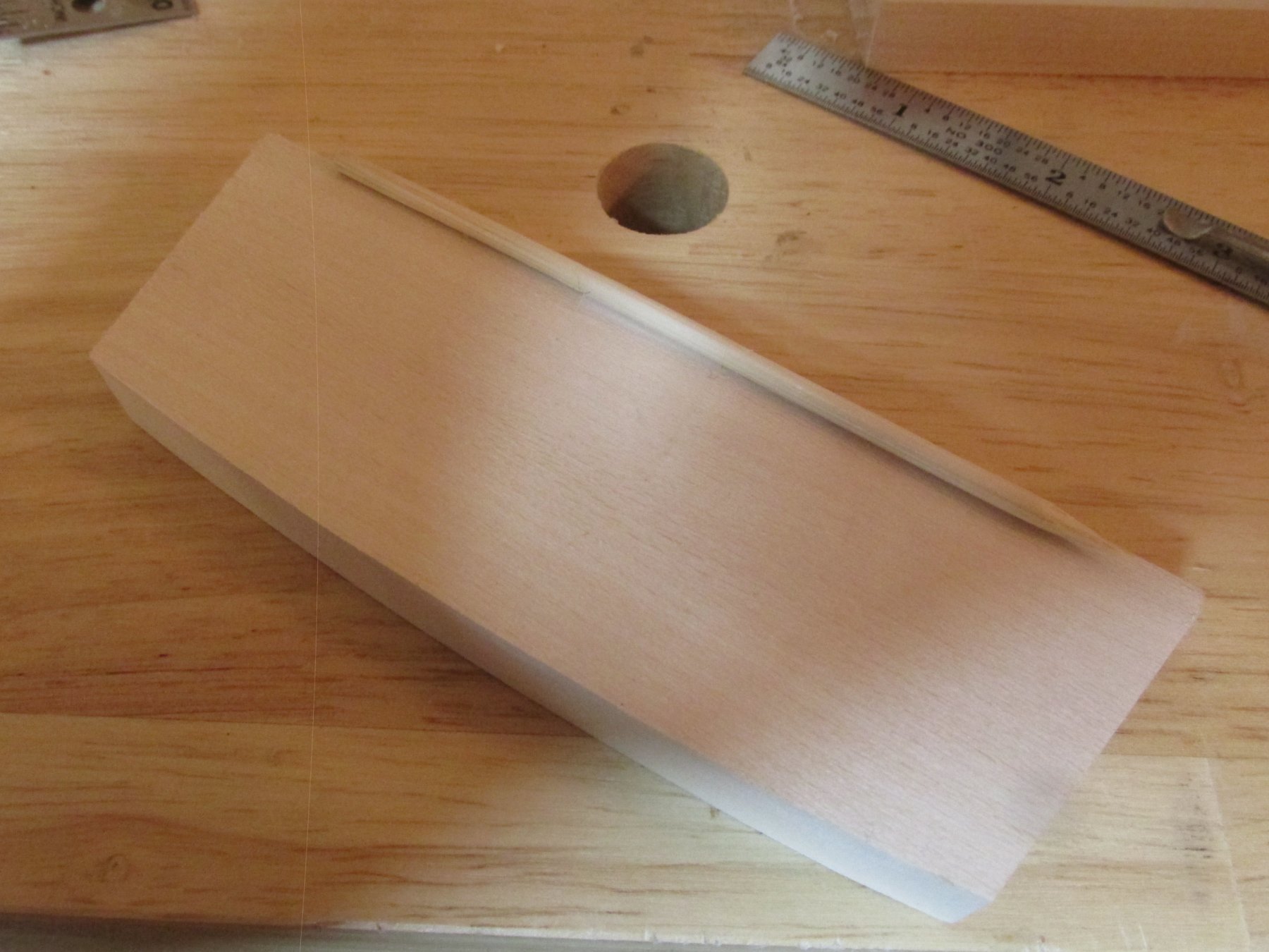
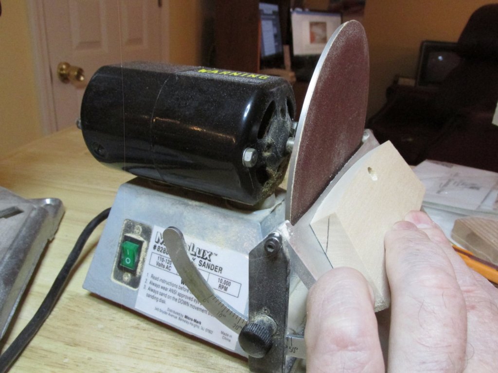
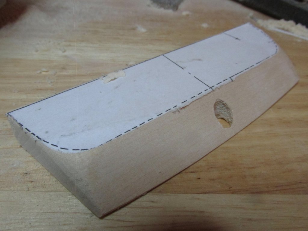
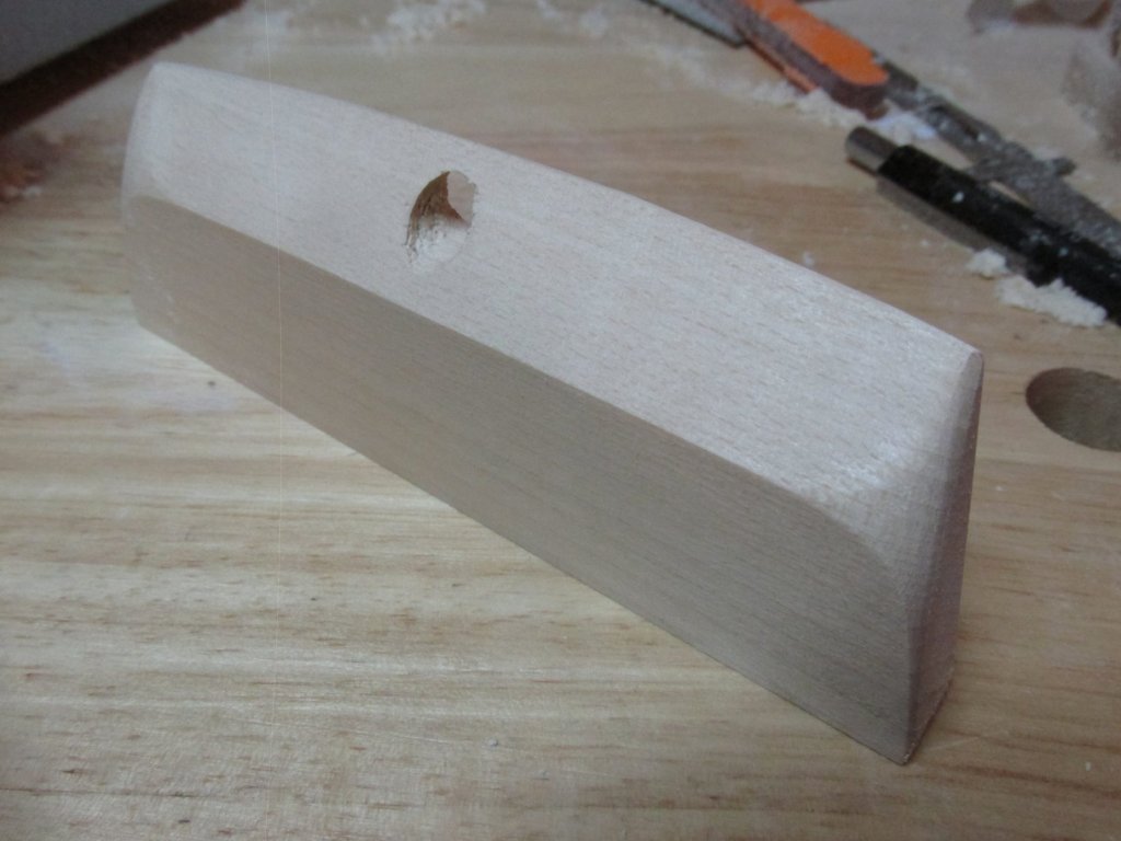
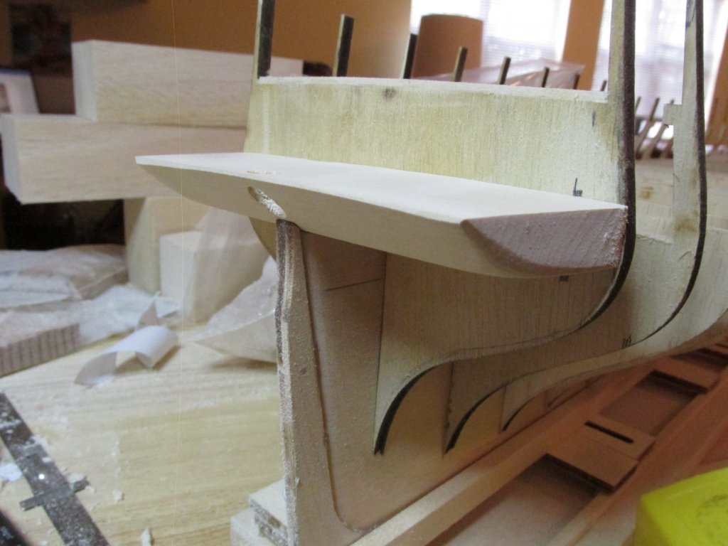
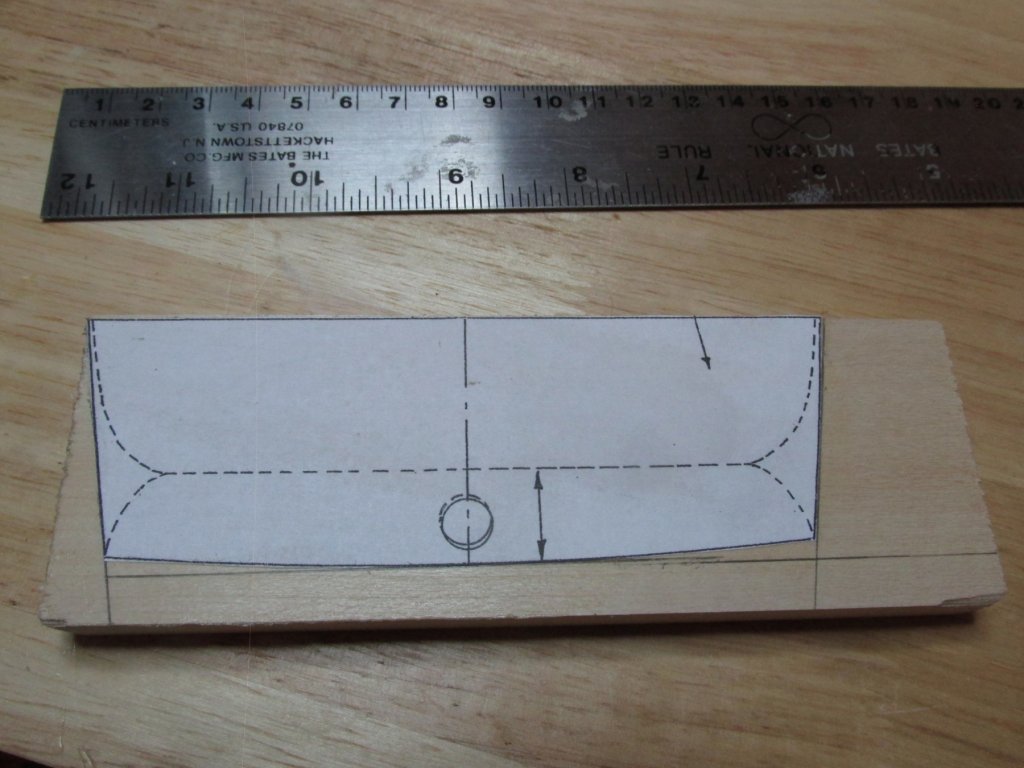
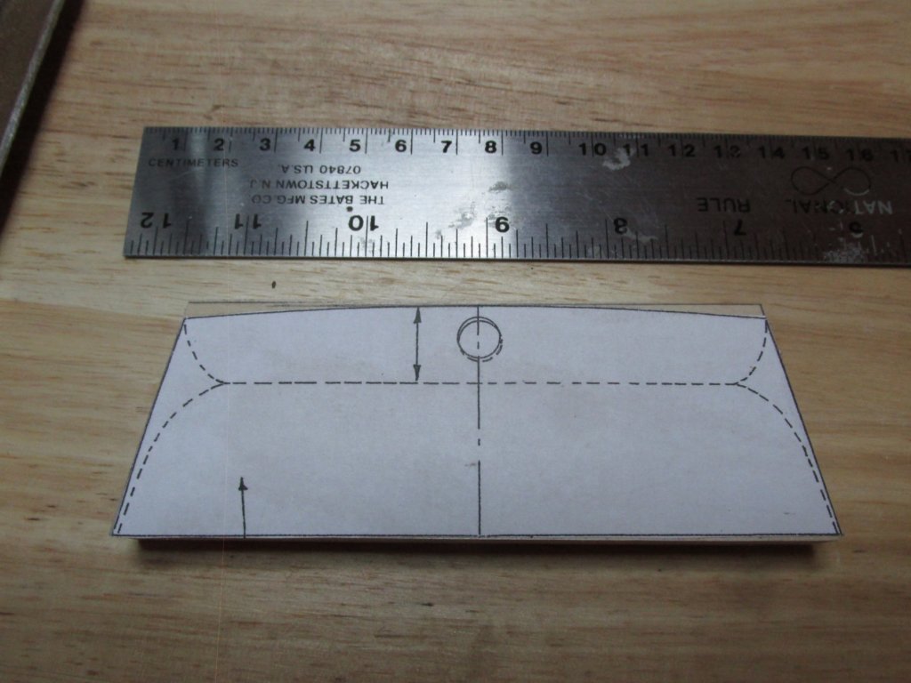
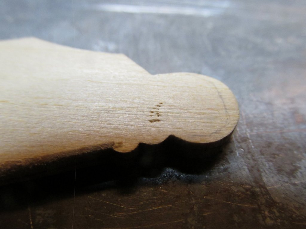
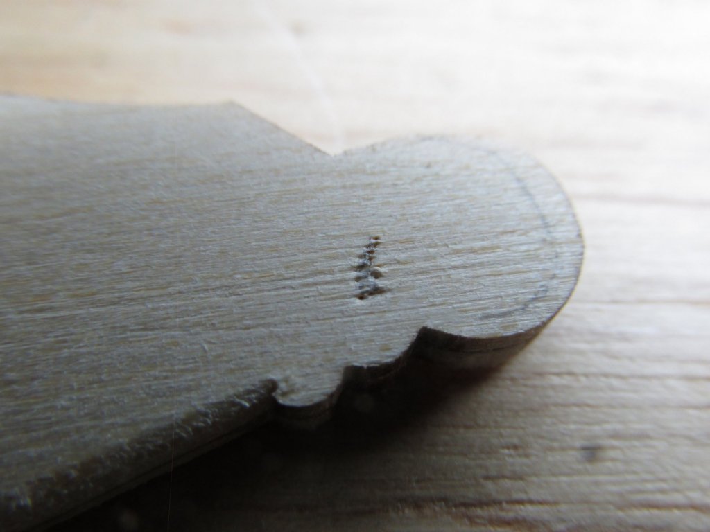
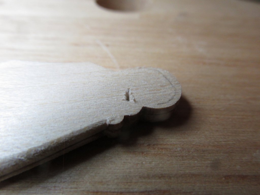
The top surface is slightly rounded, dropping down at the sides. I used a sandpaper block to create the curve. The aft edge has a slight rounded profile in the plan view which was create by carefully following the lines on the template. The aft edge is also angled in at about 50 degrees which as it turns out is the maximum my disk sander will handle. By keeping the wood flush to the plate and slowly feeding it into the spinning sanding disk using lines I drew on the sides as guides, a nice edge was obtained. Finally, the aft edge has a rounded bottom corner but an angled top corner. This was created with the sandpaper block. At this point, I got a very pleasant surprise, when I placed the completed transom filler block and dry fitted it on the stern post, it fit like a glove on the very first try. That doesn’t happen very often.

-
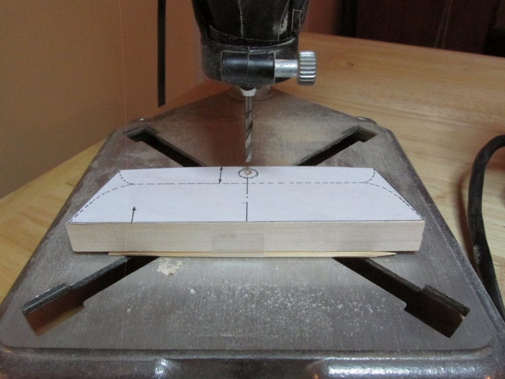
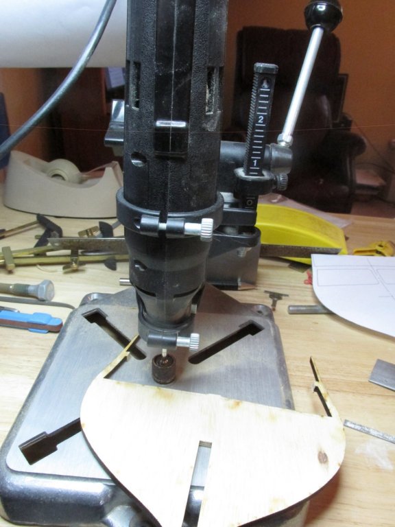
There is a rudder post hole which must be drilled at a slight angle parallel to the stern post. This is easier done now, before the aft edge is created. I found that if I taped a bamboo skewer to the forward edge I got the right pitch for the hole. Using my Dremel drill stand, I drilled a pilot hole with consecutively larger drill bits until I used the largest bit that would fit in the rotary tool. The resulting hole was still smaller than the required 5/16” diameter I needed. This was done using a full-size hand held electric drill with the 5/16” bit. I would have used a drill stand if I had one of the proper size, but the pilot hole did its job.

-
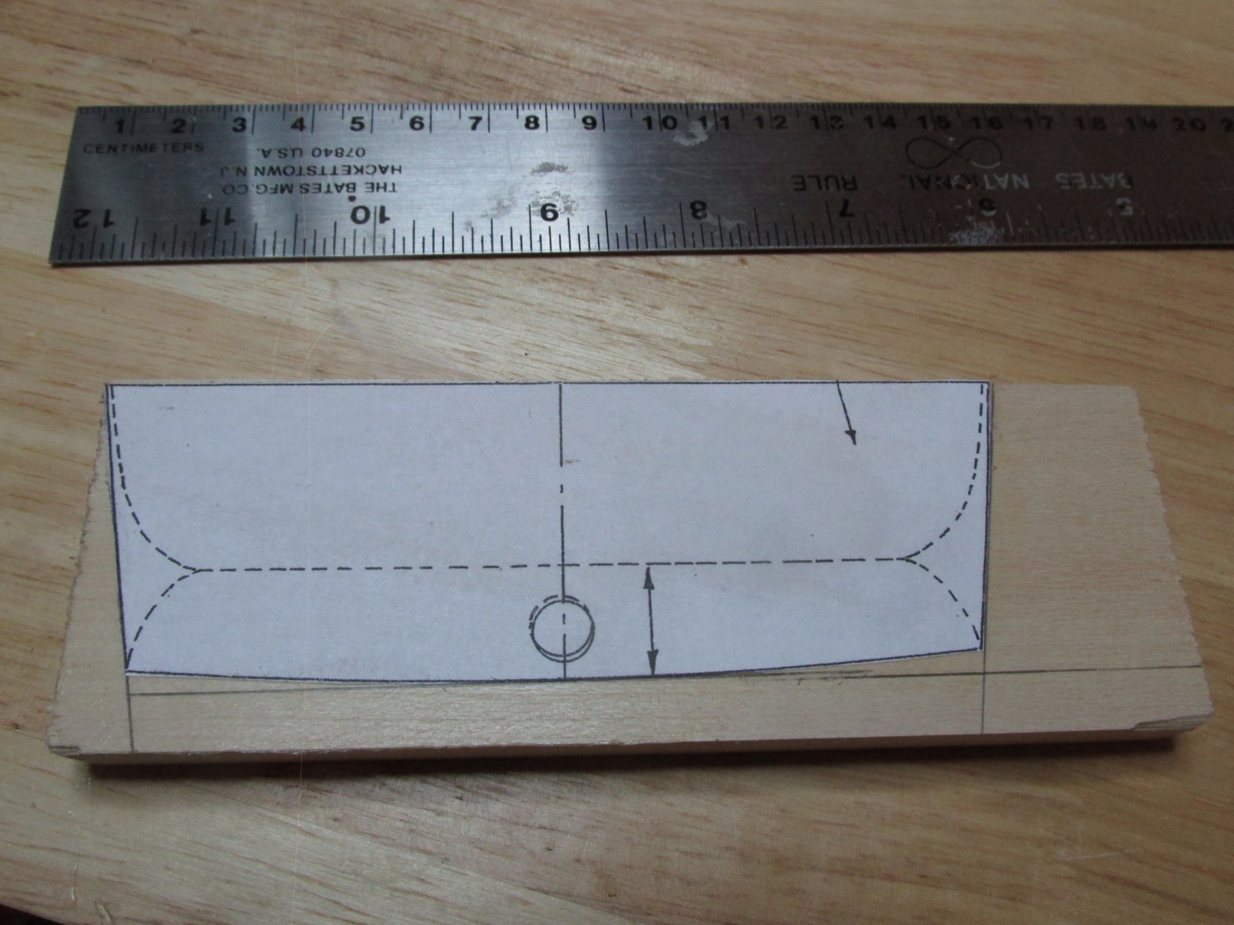
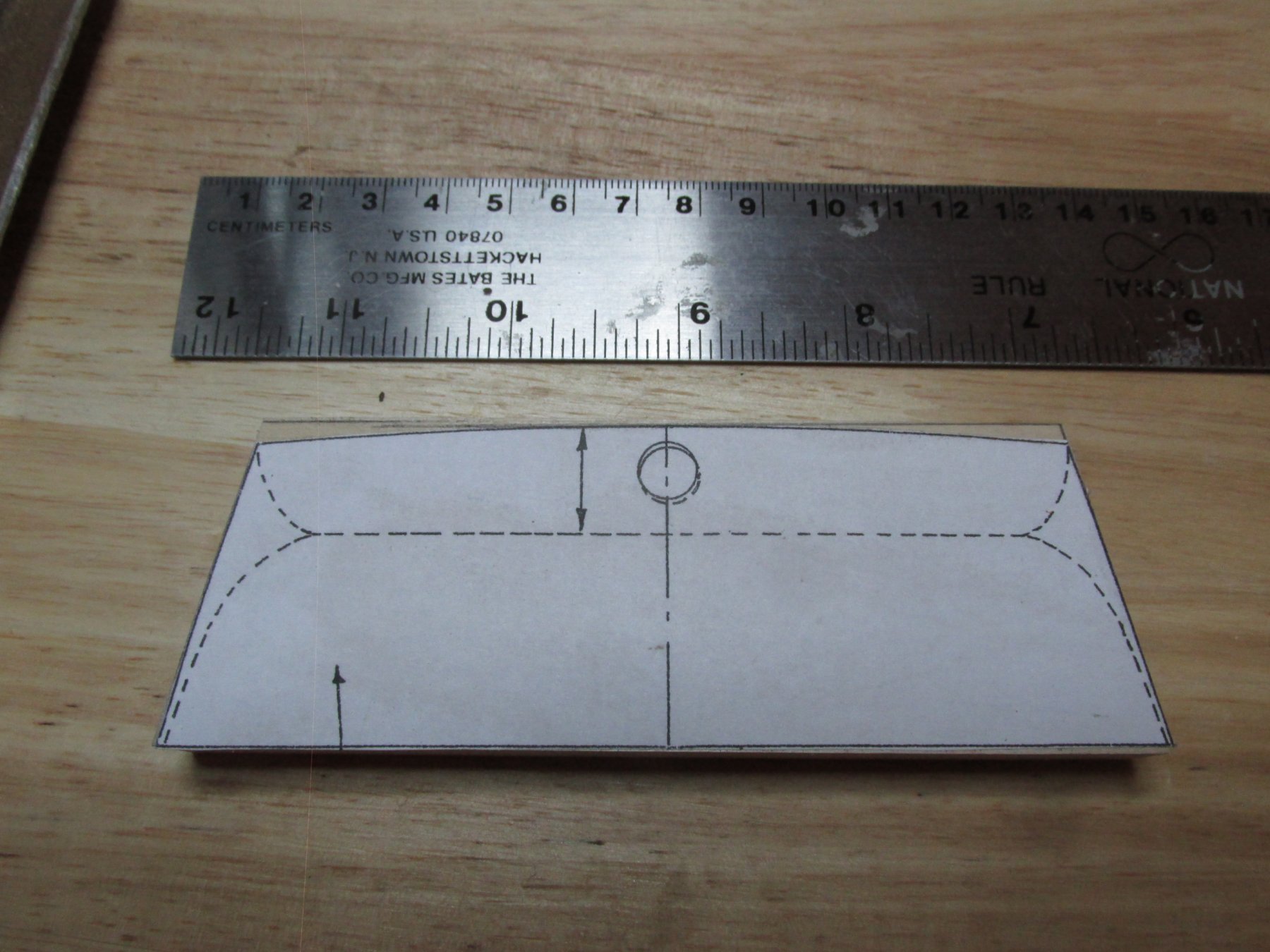
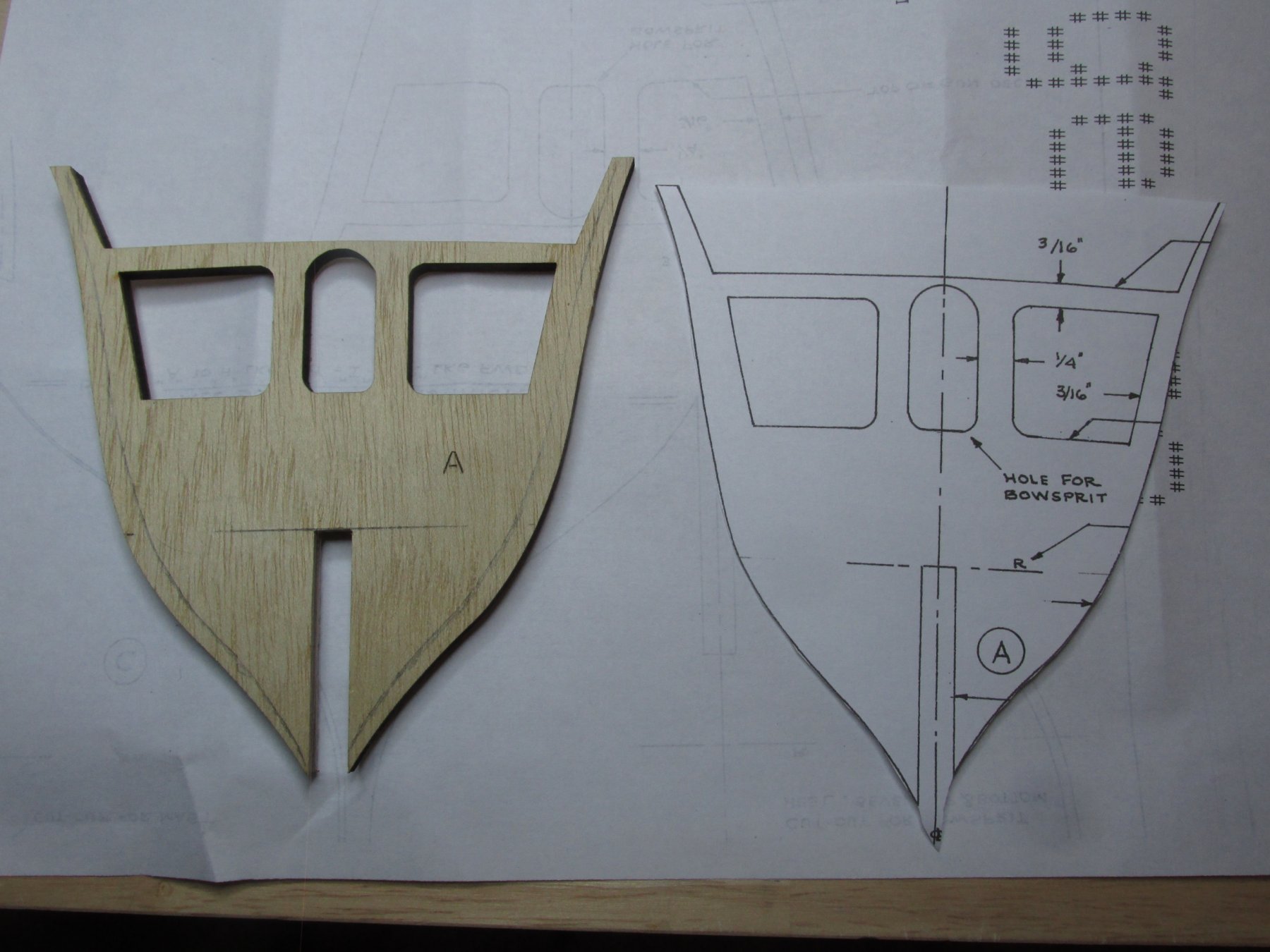
Transom Filler Block Using the kit plans as a template, the plan view was pasted with rubber cement onto a piece of basswood supplied by the kit for this piece. The transom filler block was cut out using the Byrnes saw.
-
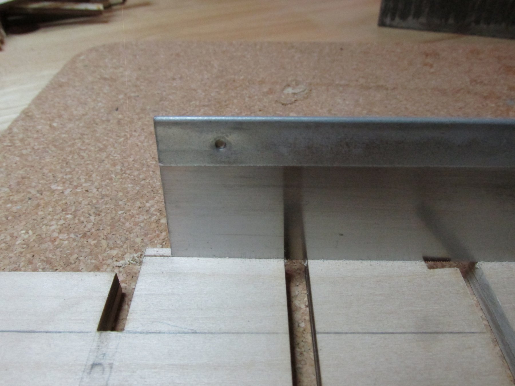
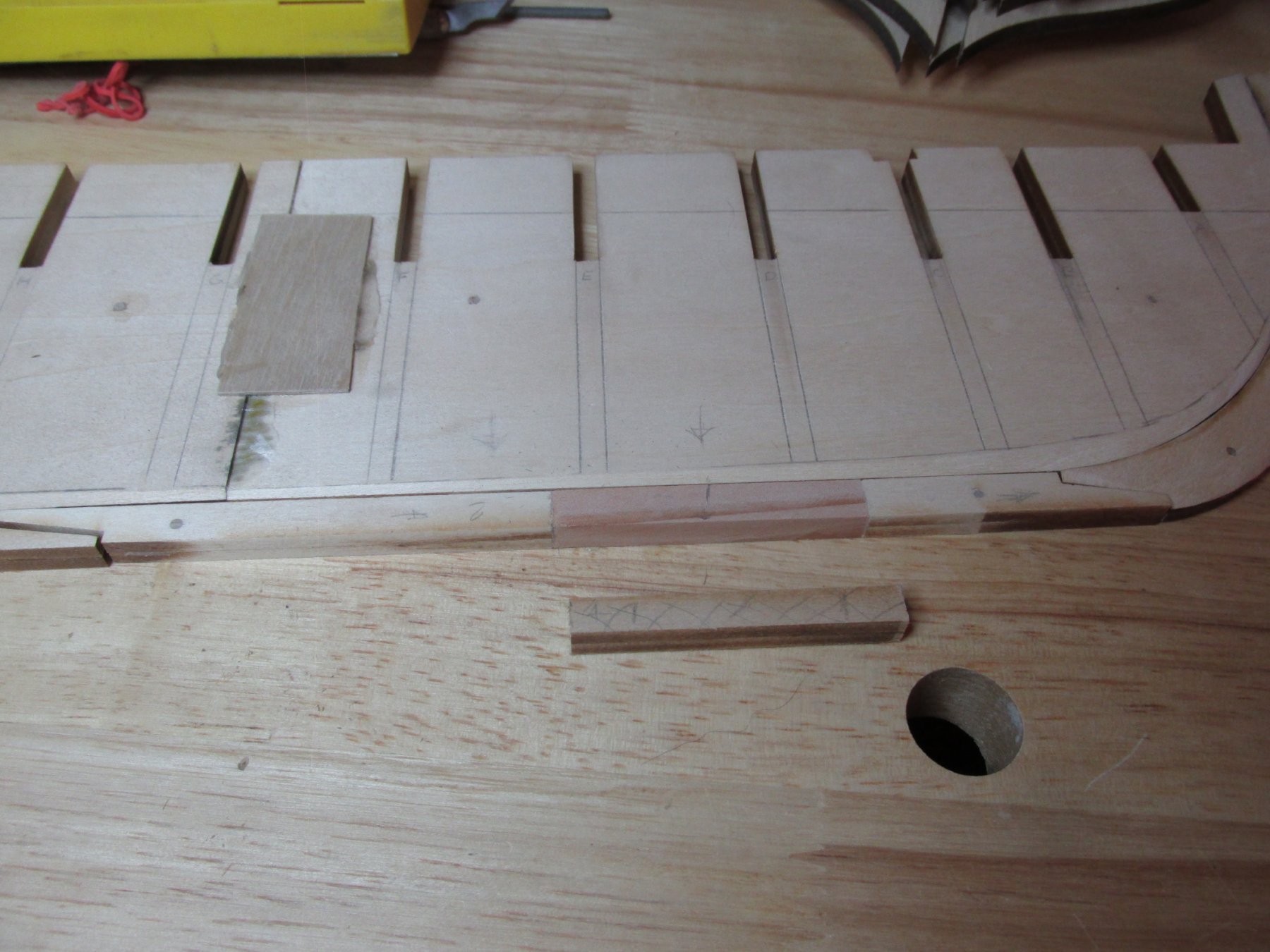
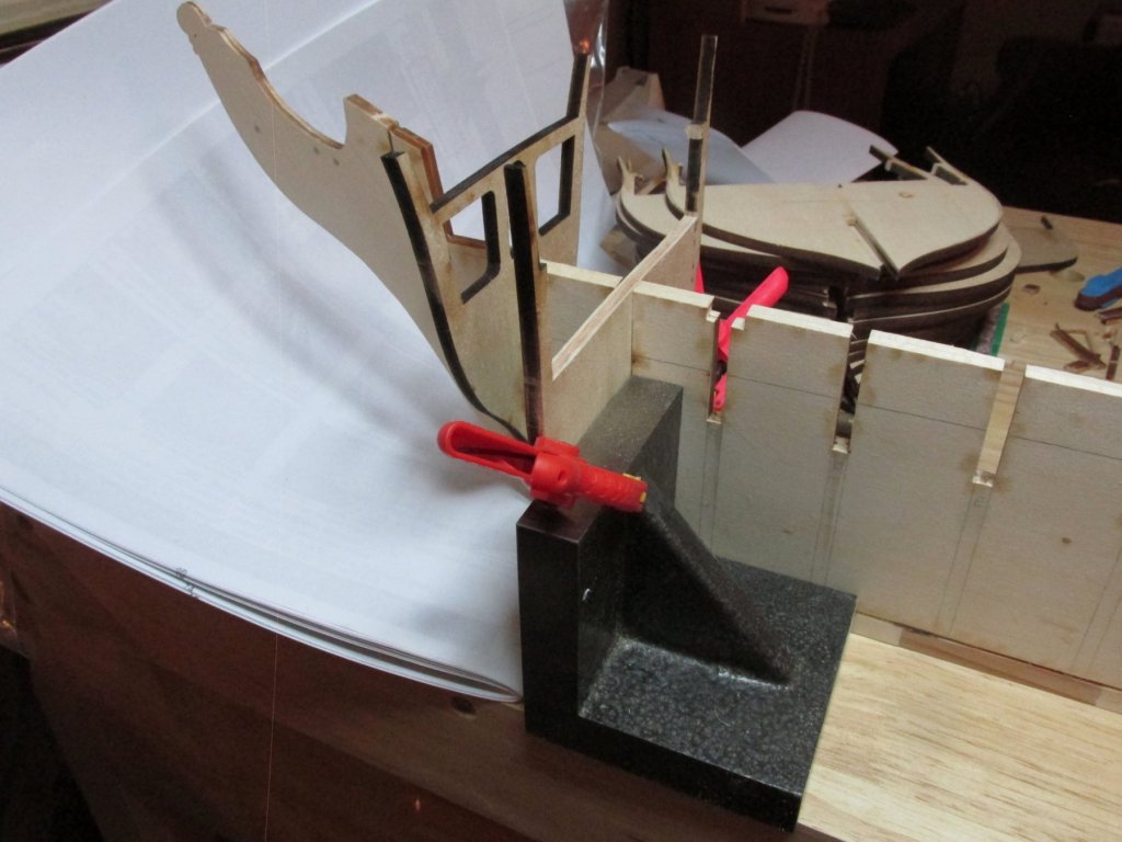
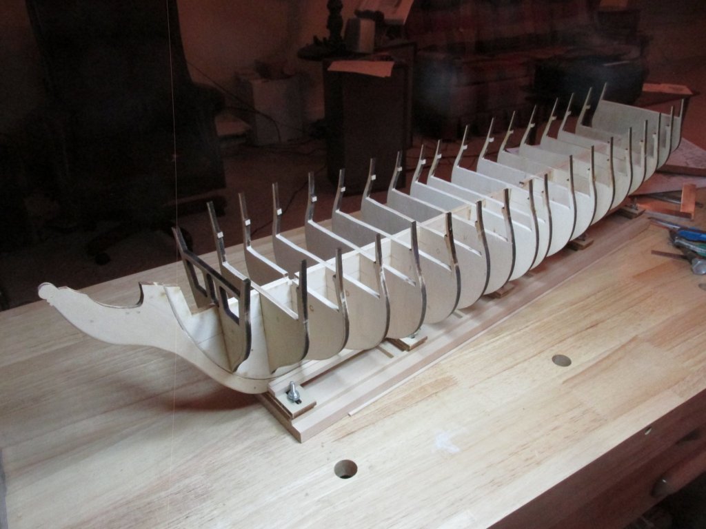
The bulkheads were installed one by one using a set of heavy angle irons I got from Micro-Mark when I started my Rattlesnake. After I took this picture, I rotated the angle iron onto its side, so I could clamp to both the bulkhead and the keel. I just forgot to take another photo.
-
Continuing with the keel modification, the three masthead notches were extended 3/32” to compensate for the gun deck modification. Technically this did not have to be done because once the plywood and decking are installed and mast hole are drilled, the length of mast notches should match the original length of the notch cavity. I just wanted additional strength. I just have to remember to extend the base mast lengths by 3/32”.

-
You have no idea how big the Screw-Up Club is!! I'm a lifetime member too.
- 742 replies
-
- 7
-
-
- constitution
- frigate
- (and 1 more)
-
Oh, I'm really sorry. The good news is that 99.999% of the people who will see your model won't even take notice and won't know what a quoin is let alone whether it is correctly depicted. Ours is a lonely art, only you and God know what is right or wrong in our models. Jon
- 742 replies
-
- 5
-
-
- constitution
- frigate
- (and 1 more)
-
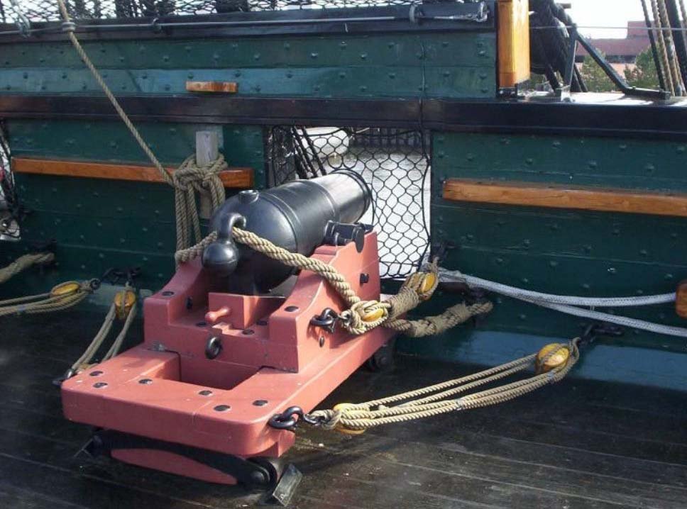
Dave, what you say about that cannon pictured is true...except the cannonades (which are not accurate to the style of 1812) are a bit different. They have the groove in the quoin. Just to make things a bit more confusing Jon
- 742 replies
-
- 3
-
-
- constitution
- frigate
- (and 1 more)
-
Tom, talk about flying blind, when I started my Rattlesnake, I didn't even know online build logs existed. I stumbled upon the the Hunt practicums, and without that, I would never have even contemplated building a square rigged ship model. Now I have a wealth of info for the Constitution. The fact that I can see what others have done right and especially what they did wrong and the resulting consequences, really teaches you. So OK, you were flying blind, but as you learned, so did the rest of us who followed your work. Thank you for documenting it. Thanks also for the Lego offer, but as I said, my nephews and their kids have more Legos then they know what to do with. If I need any, that's where I'll have them sent from.
-
Meddo, you're probable right, but I was a deprived child, I never had any. All I had was the Gilbert Erector set. My three nephews had generous parents (my sister and husband) and they built not just buildings, but complete cities with all the required (and unrequired) roads, vehicles, figures, and other accessories and still had buckets (literally) full leftover unused. They gave them to their kids who are now enjoying them, supplemented with the latest stuff of course. Unfortunately they live in Seattle and Connecticut; I live in South Carolina. Sigh.
-
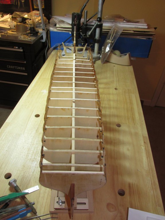
Tom - I used your build log to guide me through this stage of the kit bash process. If I had paid more attention, I would have cut the spar deck supports off after I removed the excess wood from the gun deck support like you did. You were able to use the spar deck supports to align the bulkheads when stacked together to smooth them all out. I had to use the spar deck support stubs; a bit more difficult. I still have to deepen the mast notches. I won't be able to use Lego blocks like you did to align the bulkheads on the keel since I don't have any. I'm a life long bachelor, so no kids, but I have other tools. Between you and xKen and a number of other builders, I should have a nice guided tour of how to supplement Robert Hunt's practicum.
-
Job well done!
-
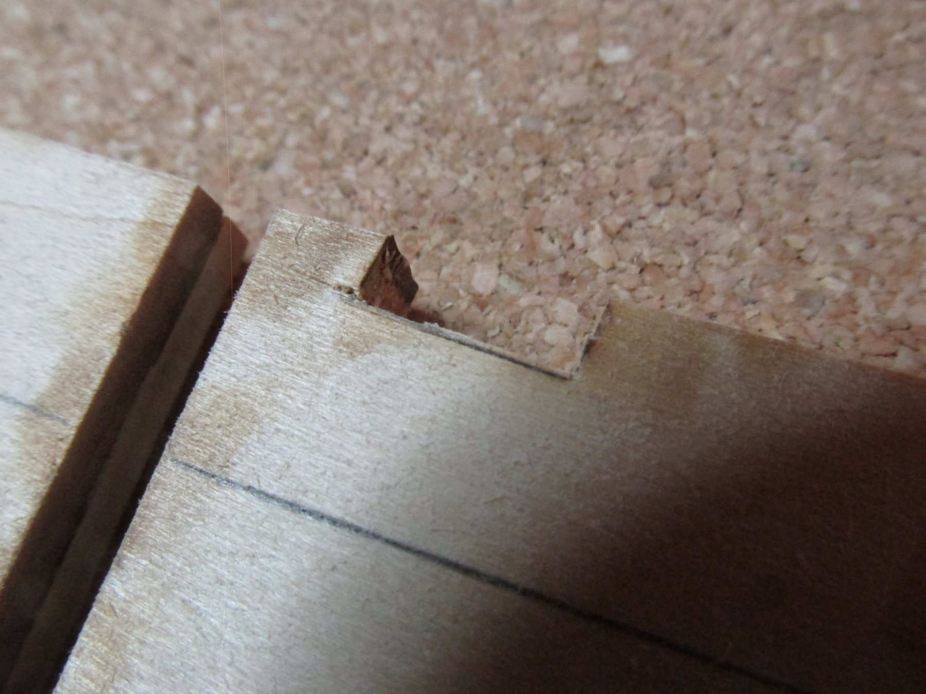
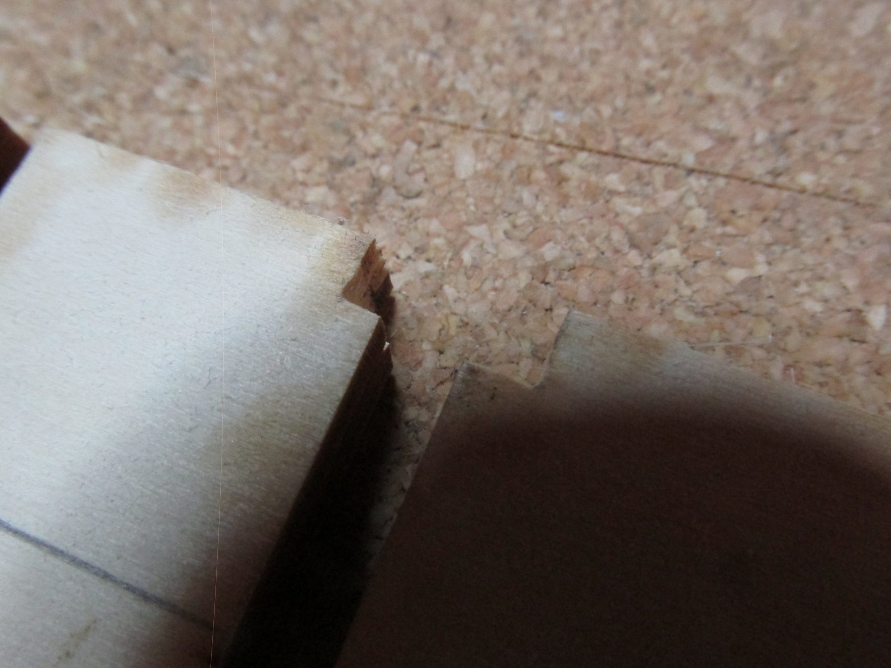
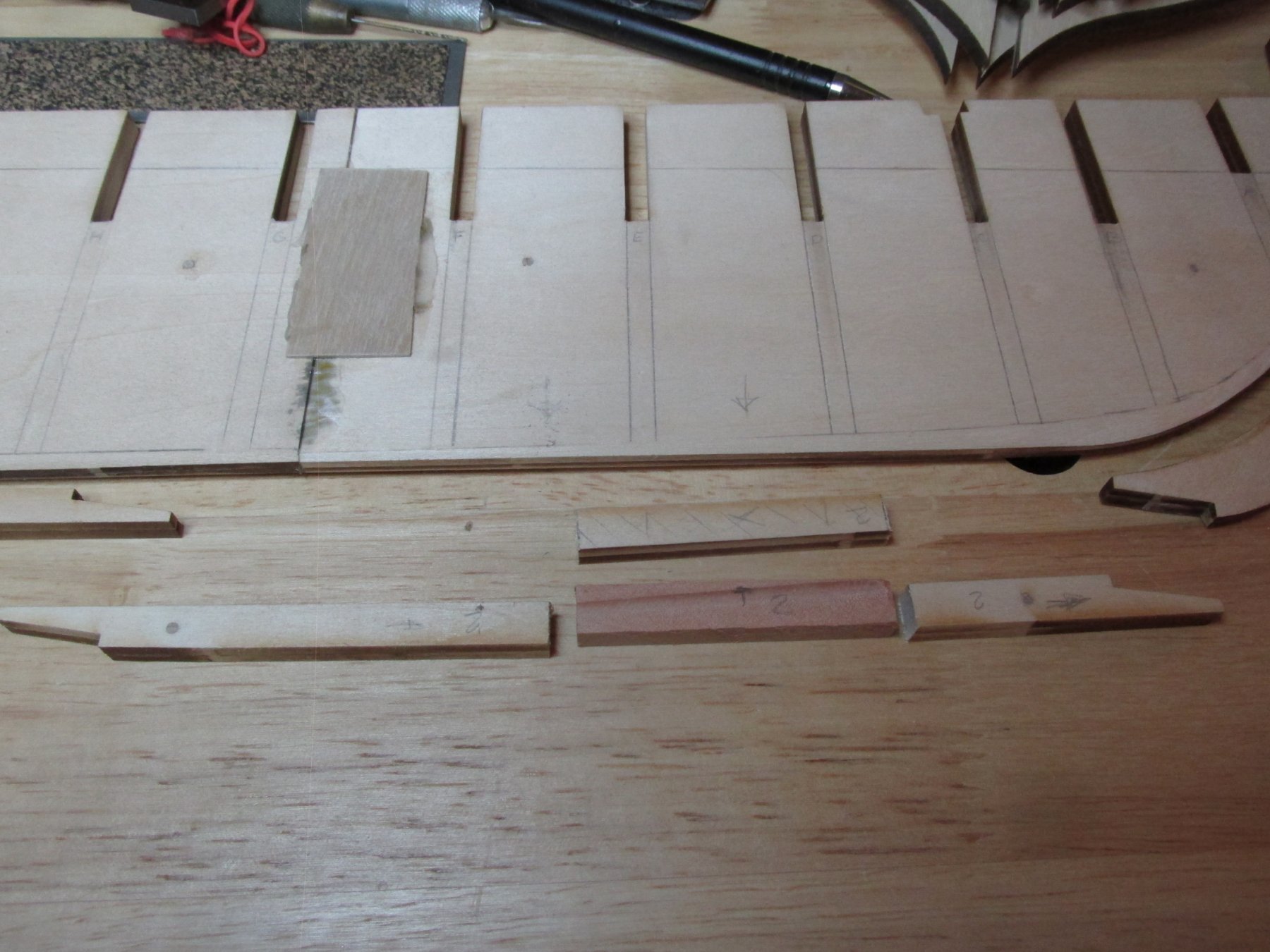
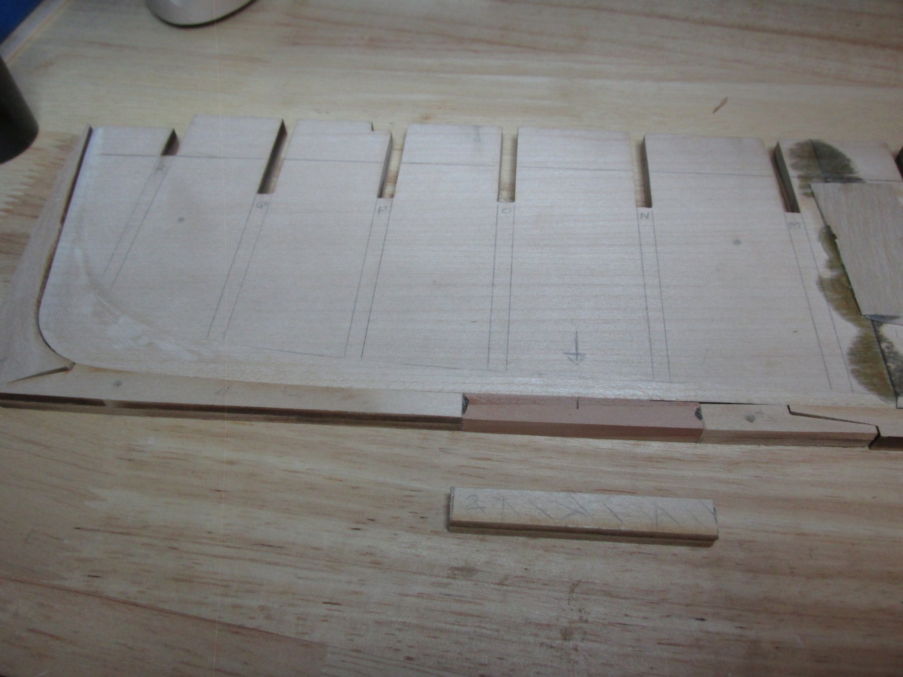
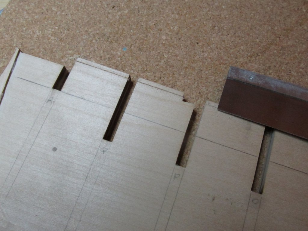
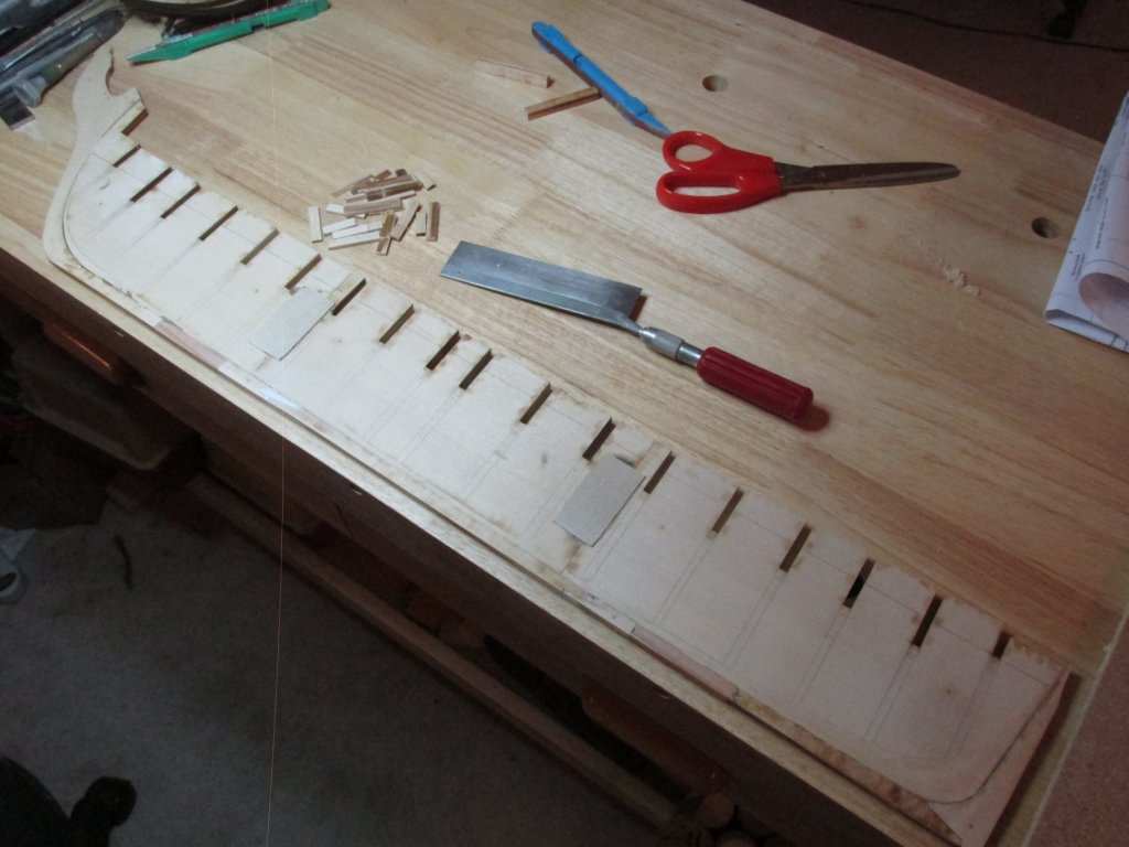
The Plunge Being the “I think I can do anything provided I have something to follow” guy, and since there are a lot of great build logs out there, I took the deep plunge into the unknown (for me at least) and decided I did not like the concept of dummy cannons. I wanted a full set of “real guns” on my model. That meant to accommodate a layer of 1/32” plywood base and 1/16” decking planks, I had to remove from the bullheads as well as the keel 3/32” of material. Making a mistake here affects just about the whole build. Now what is the point of adding a full set of cannons to the gun deck if you cannot see them? That means I will have to provide some mechanism so that one can see, at least in part, the gun deck and that also means I will have to populate that deck with all the details one would expect to see. I just made this project juuuuust a wee bit more challenging. The spar deck cross beam supports of the bulkheads had to be removed. First because the bulkheads are made of plywood and was charred in the initial laser cutting process. Second, access will be needed to the gun deck for the installation of all decking, guns, and details. Third, because I assume that some of the replacement cross beams will be exposed and will need to be more realistic. The 3/32” lines were drawn along the top of the gun deck cross beam support of the bulkheads as well as the top of the keel bulkhead with a compass set to 3/32”. This was done because both the beams and the longitudinal length of the deck are curved. Using a ruler would have messed up the sweeping curves. The cross and vertical supports were cut off first using a fine tooth saw. The stubs of the cross support were left in place so that the replacement cross beams could easily be re- attached. Using my rotary tool as a drum sander, most of the now excess wood above the 3/32” line was removed from the bulkheads. The areas in the corners where the drum could not reach were removed using the fine tooth saw and files. The wood on the keel was removed using just the hand saw.


-
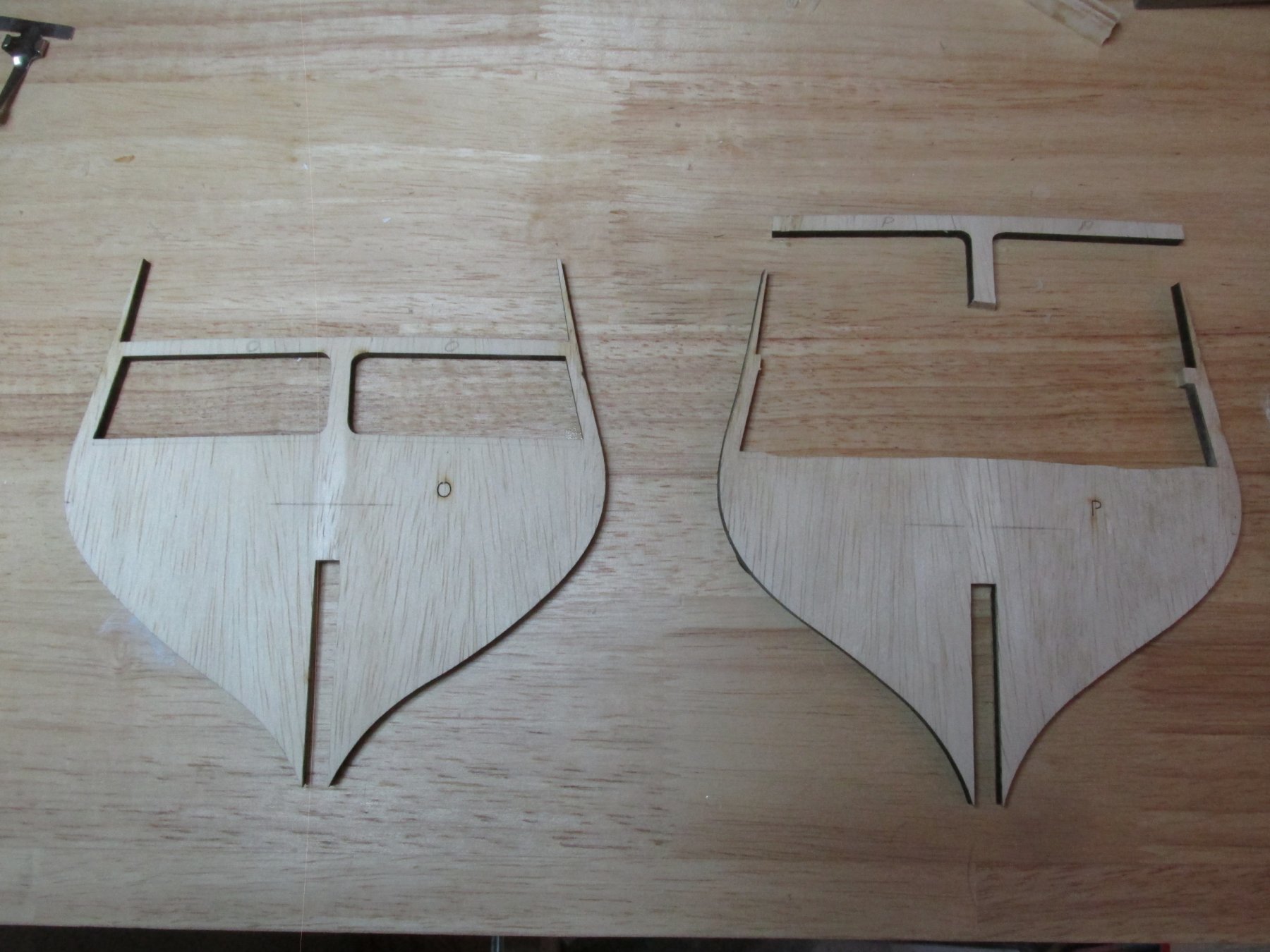
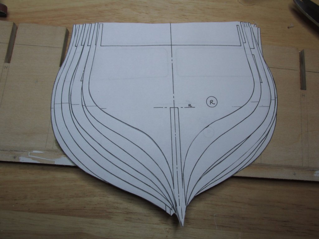
Bulkhead Preparation The first thing I thought I should do was add the bevels to the edges of the bulkheads as shown in the Hunt practicum. I cut out the patterns of each bulkhead from copies I made of the plans. For those bullheads that had a bevel, the pattern showed the bevel on the right side only. By flipping the pattern over, I was able to trace the bevel lines onto both sides of the bulkhead. Now as many of us Conny builders have discovered, neither the laser cut bullheads, nor the drawings are exactly symmetrically cut or drawn, and nor do they necessarily exactly match each other. For this reason, I chose not to add the bevels before they are fastened to the keel. The bevel lines I drew will only be used as a guide and the bevels themselves will created once the bulkheads are in their final position and glued into place.
-
Cpt Jack Sparrow - I look forward to watching you build your Connie. Dave (DocBlake) - Good to hear from you again. It was nice to finally meet you at the St. Petersburg NRG convention; just sorry we didn't really get a chance to chat very much. I've learned my lesson with Mr. Hunt's practicums: they are a great guide, as I could not have done my Rattlesnake without it, but don't follow them word for word. The choices he makes may not be the ones you would make. I have some wonderful build logs to follow now and I hope to glean the best from all of them, including Mr. Hunt's. Jon
-
I've never heard of the nautical term coxcomb (alternate spelling - cockscomb) before. I did a search for the term and the only nautical definition I found was: A serrated cleat once fitted to the yards of a square-rigged ship and used when the sail was being reefed I could not find any other details or images. Jon
- 1,348 replies
-
- 2
-
-
- constitution
- model shipways
- (and 1 more)
-
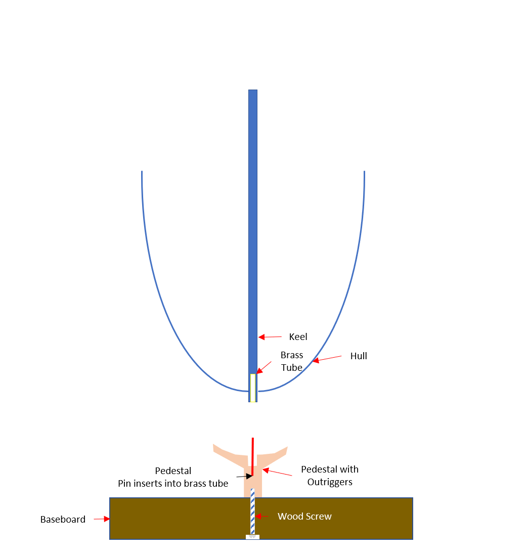
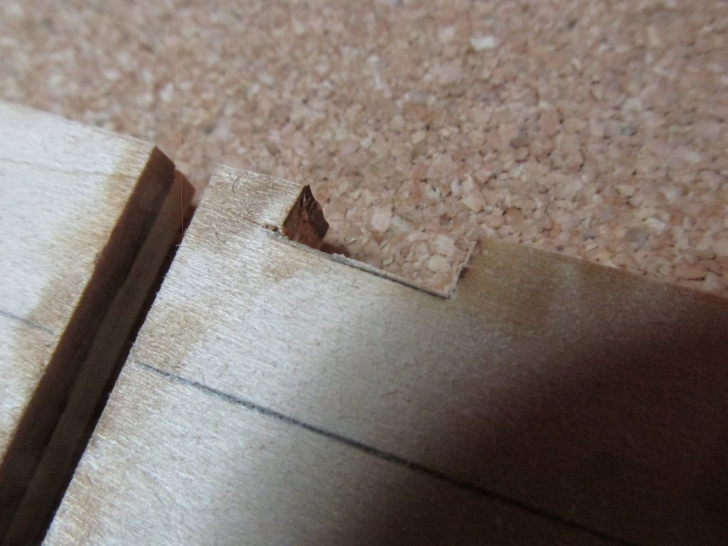
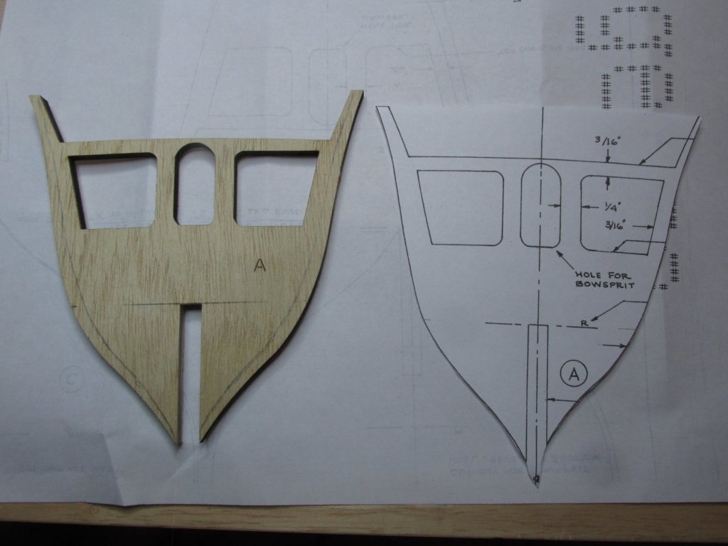
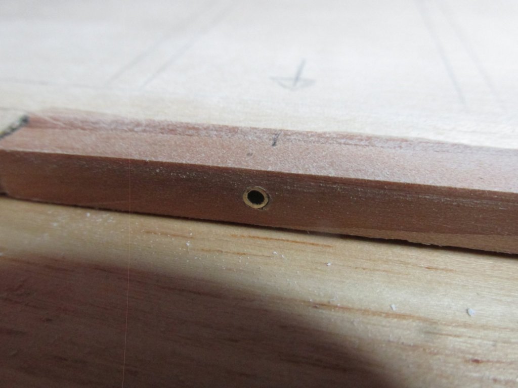
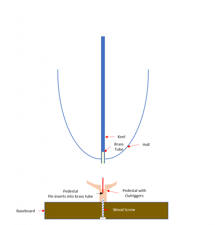
Once the oak was glued into the keel pieces, a 3/32” hole was drilled through. The keel pieces were ready to be glued to the keel bulkhead. First, I glued together the stern post to the aft keel section and the stem to the forward keel section. Then these two sections were glued to the keel bulkhead. This left a gap in the center for the last keel section. This was done this way to ensure that any errors in my cutting of the keel pieces and replacing them with the oak pieces would appear in the center of the model. Then the last piece, the center section keel was glued into place. And, as it turned out, my cutting precision left a little bit to be desired. There were gaps on either side of the center keel section which had to be filled in and sanded. I went back to the pedestal holes and drilled the holes, so they continued into the keel bulkhead. Now they were ready to have the brass 3/32” tubes inserted. I see a lot of model displays with the ship model supported by keel pedestals. I just don’t trust that the screw/bolt going up the thin keel is strong enough to support a heavy model if there are any lateral loads (bumped table, transporting, etc.). I also didn’t want a cradle support (like my Rattlesnake) because the model would be loose. I plan on using a pedestal with outriggers (like a mini cradle) so that any lateral load will be supported by the model’s hull. Bob Hunt’s practicum shows his model supported with pins protruding from the model’s keel into the pedestals. He wanted to be able to remove the model from the stand as he worked on it. I liked that idea, but reversed the pins. I can still remove the model to work on it without having to protect the pins sticking out of the model since they will be embedded in the pedestals. At the completion of the build I will have the option of gluing the model to the pins for a permanent display.
-
Note: This text is for the images in the last post. I was getting an error message when the text was pasted in. Installation of the Keel The keel was glued on in sections. First the oak wood from the actual ship was inserted into the forward and aft keel pieces. The position was dictated by where I planned to use pedestals to display the model. You can see where I marked the keel bulkhead with arrows. The length of the oak was limited to the approximate 3" square pieces of oak I had.
-
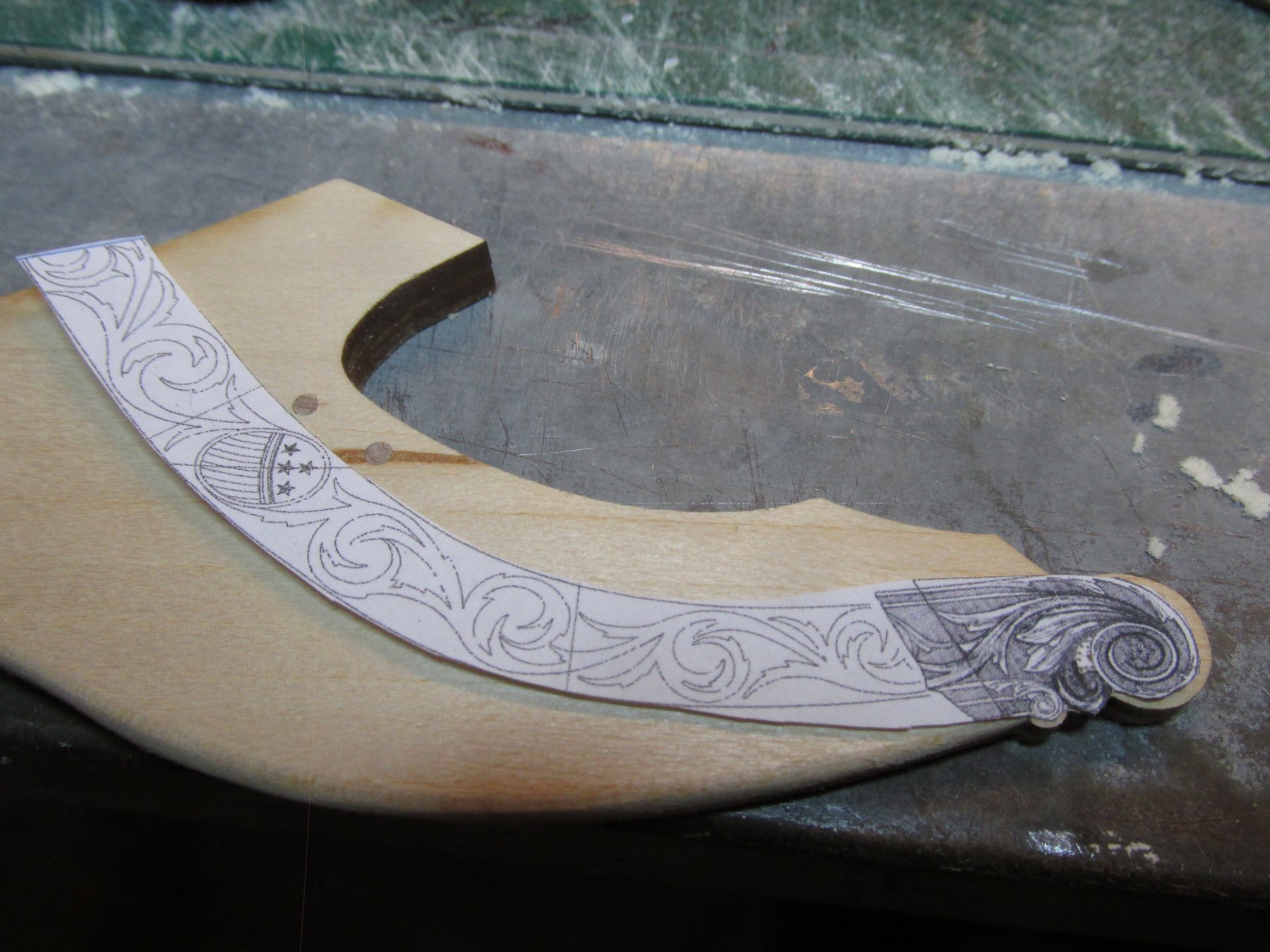
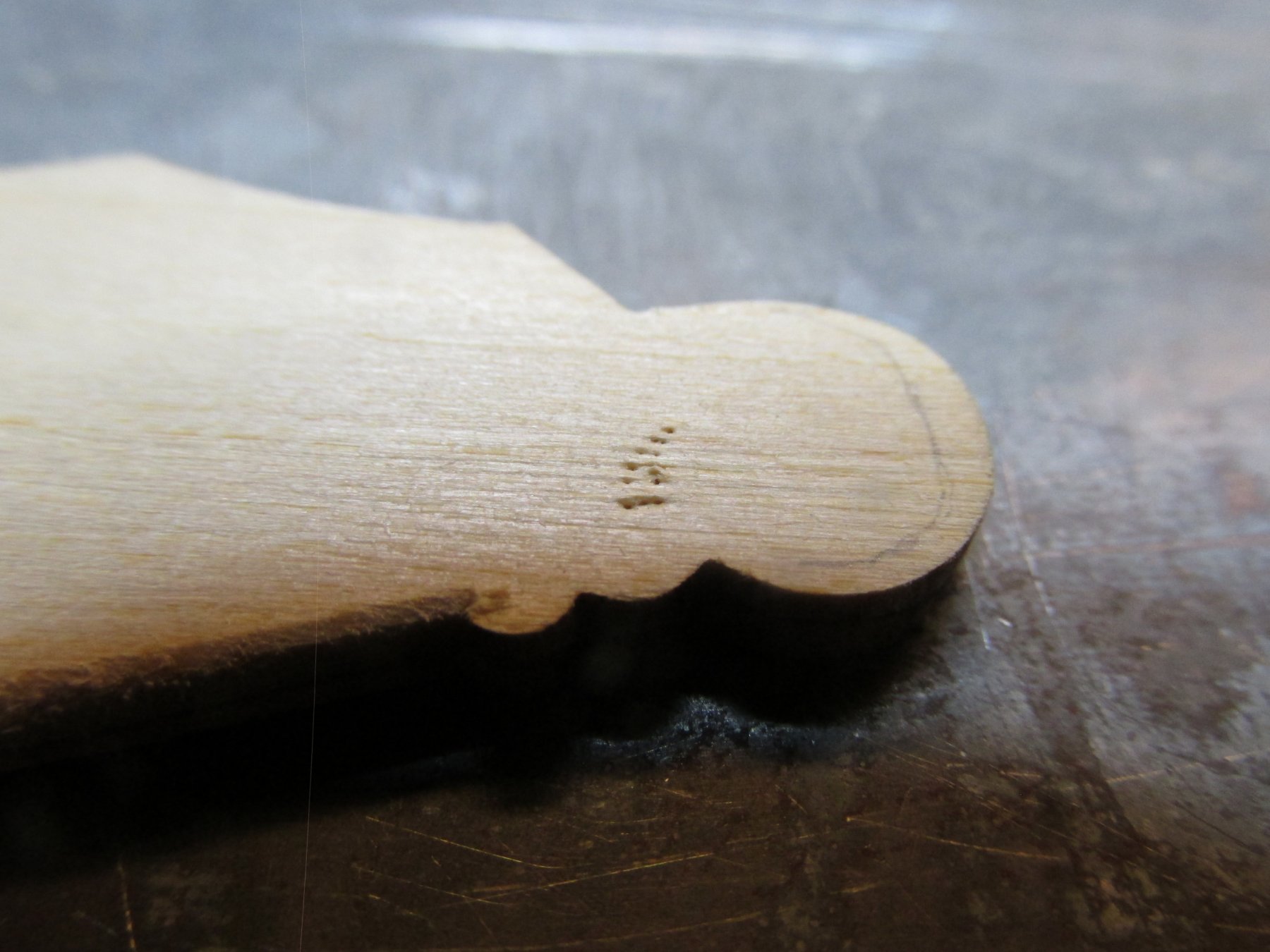
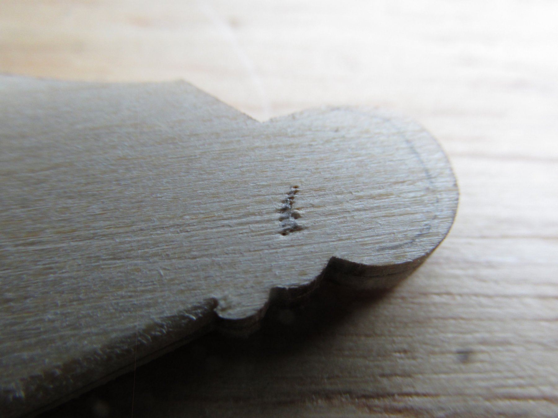
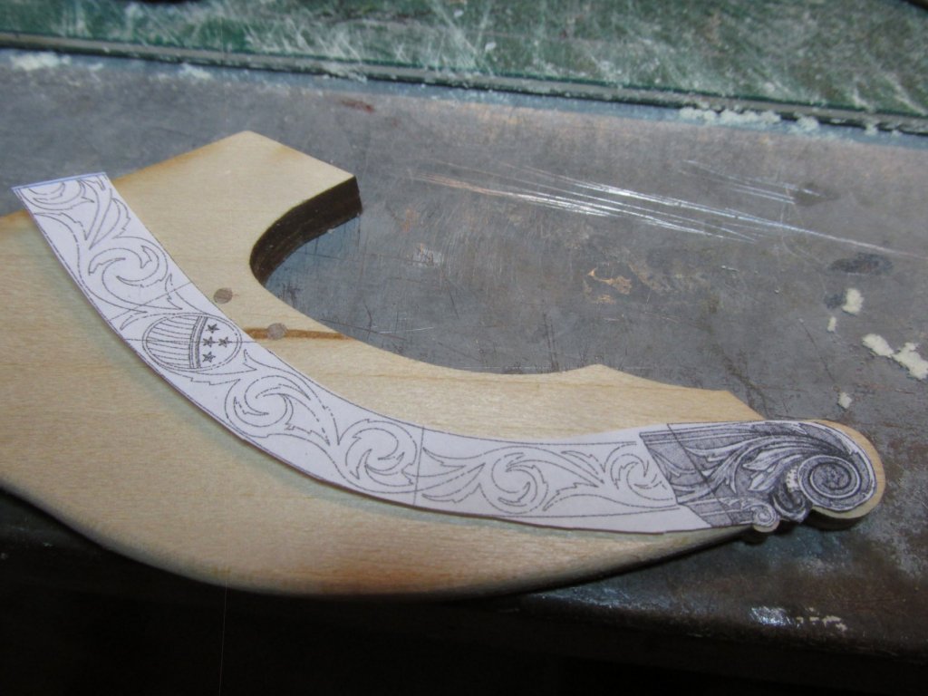
Well, the Thanksgiving bash was all it was hyped up to be. By herself, my Sister had 18 people around her table, not once for the Thanksgiving meal, but three times over the course of two days, a total 31 people coming in and out through the course of the week. How she did it, with appearing to show little effort, I’ll never know. Trailboard Preliminaries Continued OK, not enough praise for my Sister, but it’s back to business. Using the pin marks I made on the stem, I drilled out the opening and fine tuned it with an X-acto knife. I’m going to assume the opening might be a bit bigger than I made it, but I’ll address that when the trailboard carvings are made and attached.
-
Per the USS Constitution Museum’s Restoration Log, “Constitution’s Modern Armament,”: Her first 20th century restoration in 1906-1907 saw fifty-five replica guns made for the ship. All of the present guns were cast for the 1927-1931 restoration with the exception of two 1812-era replica carronades on the after quarter deck. Cast in 1981, these carronades are closer to Constitution‘s 1812 spar deck armament. The gun deck guns were cast in the Charlestown Navy Yard in 1929. The pattern of these guns was based on a British siege gun that was abandoned in Boston during the American Revolution and is currently displayed near Harvard University. The decision to cast “British” guns was made by Lieutenant John A. Lord, Supervisor of the 1927-1931 restoration. He based his decision upon inaccurate research that led the Navy to mistakenly believe that Constitution was outfitted with British guns in 1812. So, the odd ball cannonade with the elevation screw is the more accurate version. The choice is yours as the model maker…and mine too when the time comes for me to make the choice.
- 742 replies
-
- 5
-
-
- constitution
- frigate
- (and 1 more)
-
Any details as to how you made the binnacles? They look really good. In the photo, they look silver as opposed to brass but that could be just the lighting. Did you use foil or metal plate? How did you construct the ball on top of the housing? I'm trying to glean all the info I can so I know what to do when it's my turn. Thanks, Jon
- 742 replies
-
- 6
-
-
- constitution
- frigate
- (and 1 more)
-
From the pictures, it appears that the square stock passes through the chuck and through the rotary motor so you could work the wood at the end. Is that correct? I know that Ken would sometimes drill a center hole for a pin to attach two pieces. Since you didn't mentioned that, I assumed you didn't attach the tapered ends to the yard ends. I don't have a Sherline lathe, but want one. I have no real experience with a lathe/mill. Did you get a package deal on the lathe and mill combo? Was there any additional accessories that you bought that I should also consider and is there any accessory you did buy (or came with the lathe/mill) but have not found a need for? Ken told me not to buy a toll until you need it. I have learned that to be very true. I've purchased many a tool/gadget for this hobby only to find I've had to use it. On the other hand, I don't want to start something only to find I'm missing an important accessory to do the job right. If you feel these questions are off course for this log, could you PM me? Thanks Jon
- 1,348 replies
-
- 1
-
-
- constitution
- model shipways
- (and 1 more)