JSGerson
-
Posts
2,650 -
Joined
-
Last visited
Content Type
Profiles
Forums
Gallery
Events
Everything posted by JSGerson
-
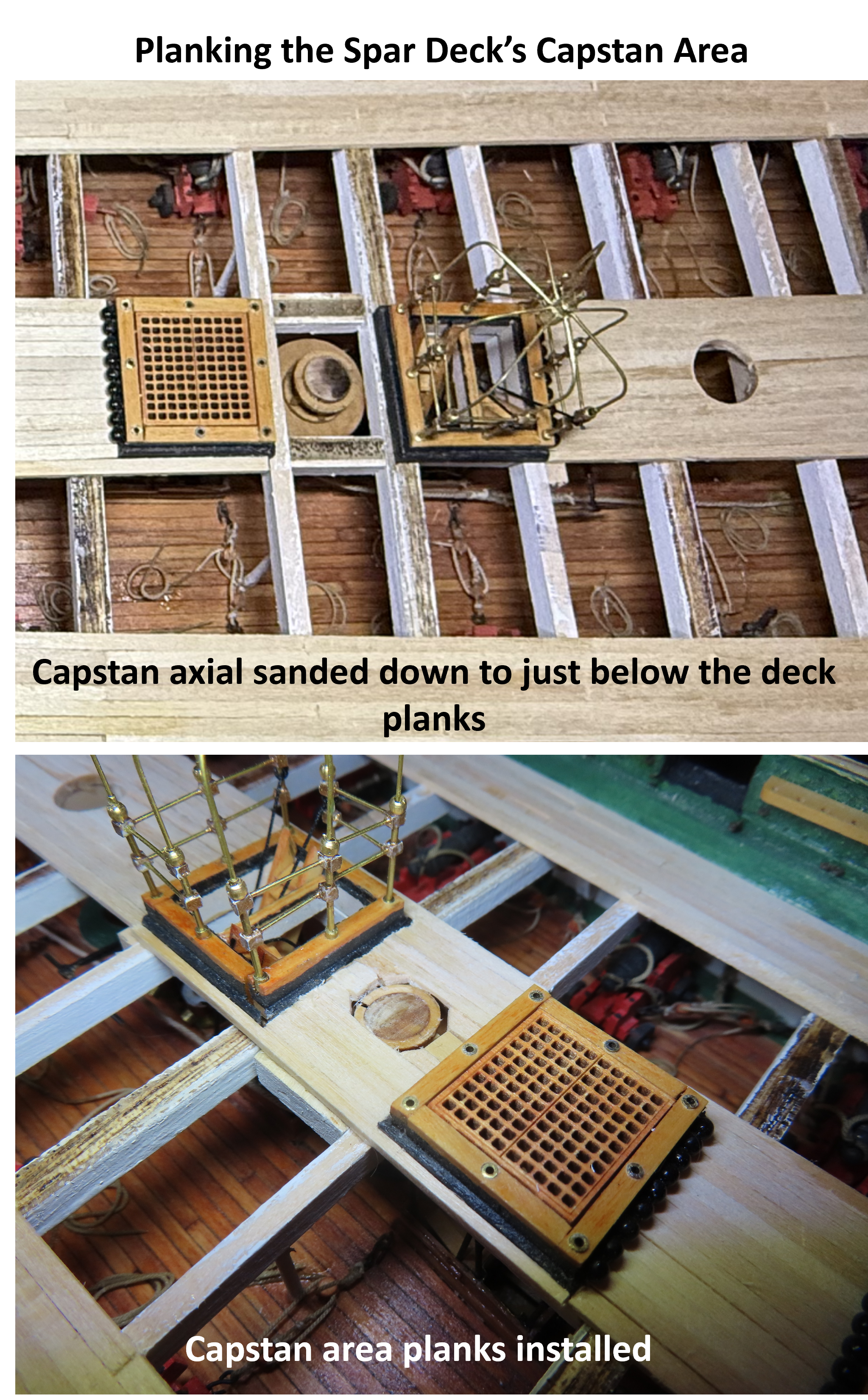
 As I examine the capstan location, I realize that I made the gun deck capstan protrude about a 1/16” above the spar deck. At the time, I was thinking that I would extend the axial of the capstan into the spar deck capstan. As it turned out, there was no reason to extend the axial. First, attempting to get a perfect alignment would be tedious and second, it wouldn’t be seen. I sanded the protruding axial so that its top was just below the surface of the planking. Now I simply planked around the spindle. The area left open will be covered by the spar deck capstan. In the end, it won’t be obvious what method was used to install the spar deck capstan as it will all be hidden.
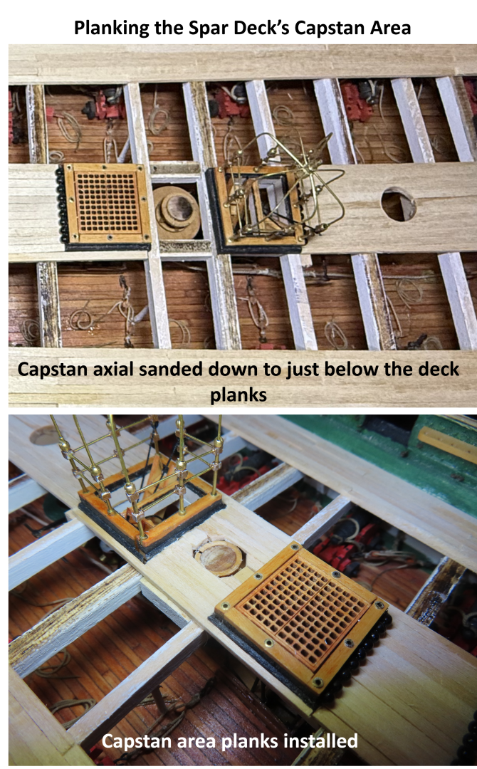
-
I've made a note! 👍 Jon
-
I know exactly how you feel. I've fabricated a large amount of stuff for my gun deck only to obscure most of it with a partial planked spar deck. We know the stuff is there, and that's what counts. If observers are truly interested in the model, they will look more closely and longer to be rewarded with more detail. The more they look, the more they will see. It engages them with the model and the builder. You've done beautiful work. Jon
-
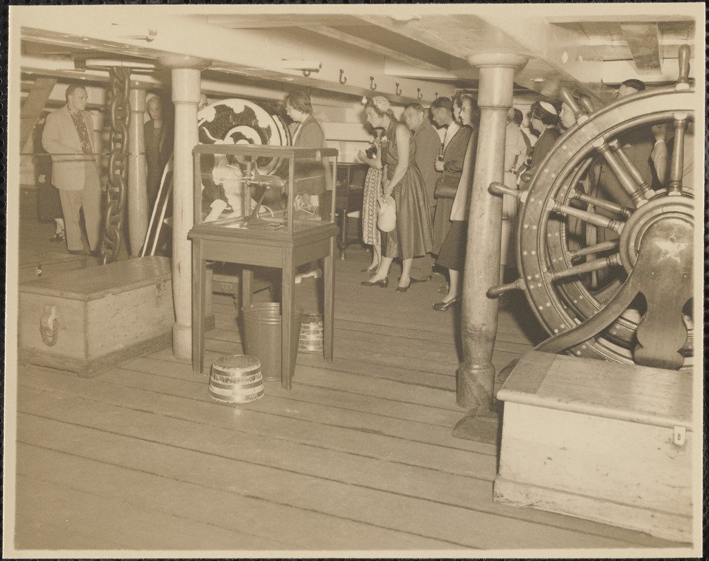
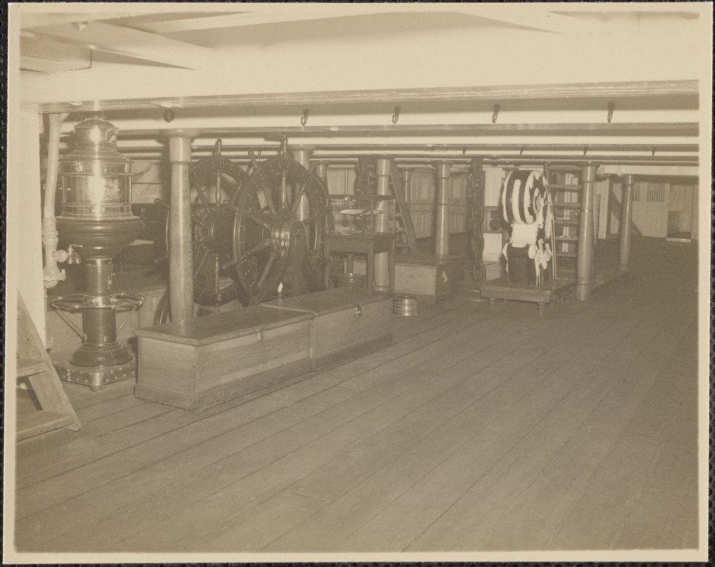
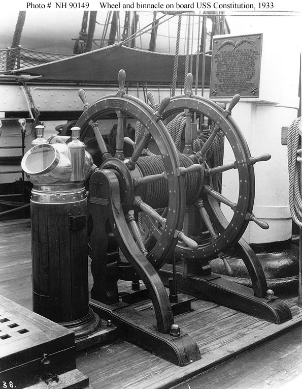
Here are a couple of more photos of the ship's wheel taken between 1940 - 1950. It looks like the wheel in the 1933 picture was removed and shown as a museum piece on the gun deck, Sorry, these images are not the greatest. Jon
-
I believe the modern binnacle was there for the practical reason the ship was on the ocean on tour under full sail part of the time and others being towed. She went through the Panama Canal all the way up the coast to San Francisco and back to Boston . Jon
-
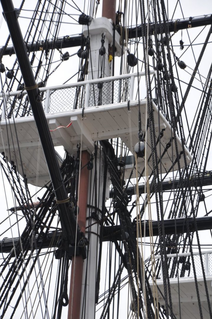
Thanks for the clarification. I went through my collection of images and found one, just one photo of the platform. It was taken during the 1931-34 National Cruise in 1933. Since the MS kit is largely based on the 1927 restoration, I'm not surprised it's part of the kit's plans. Therefore, I won't be adding it to my model either. Jon
-
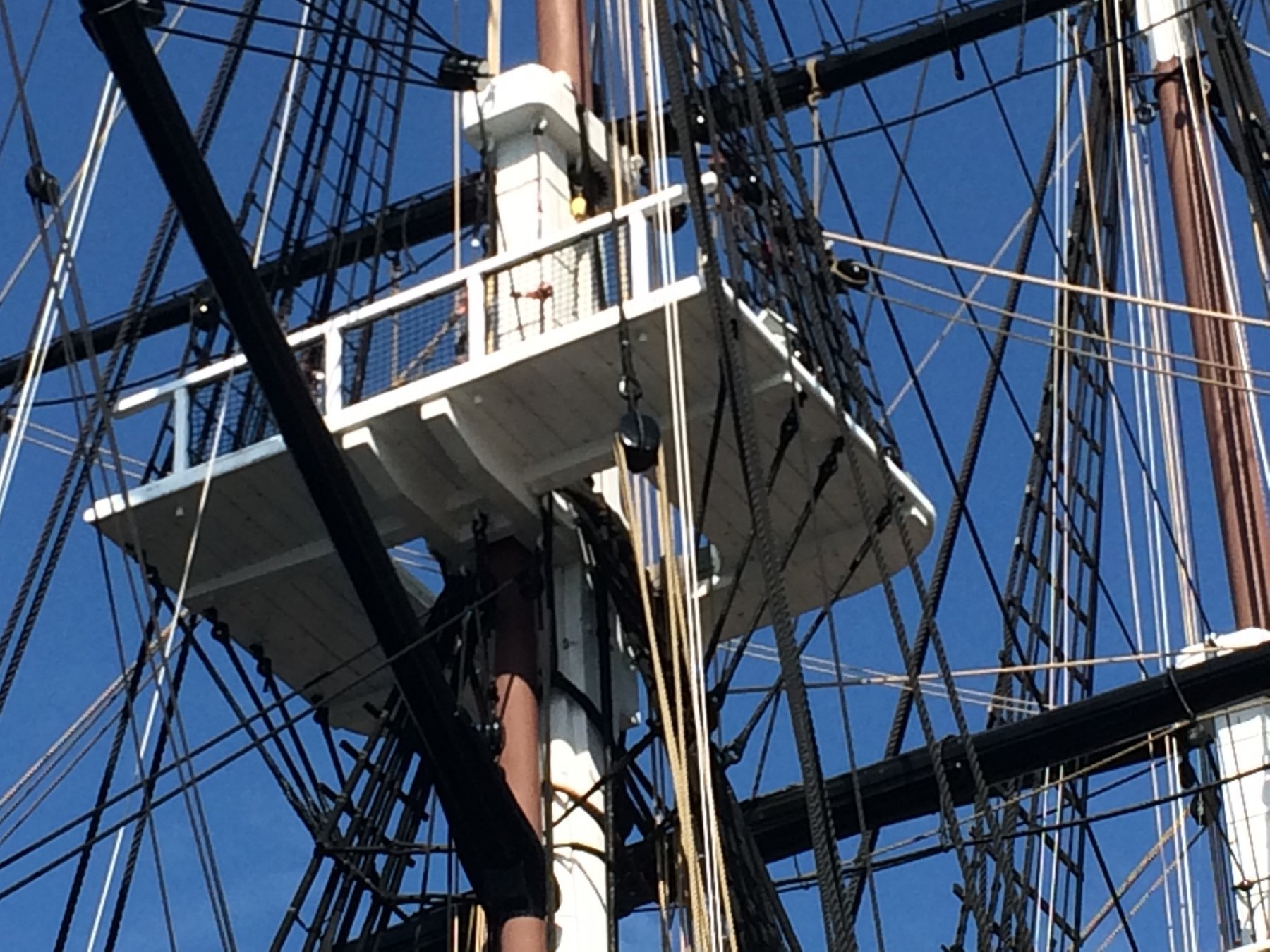
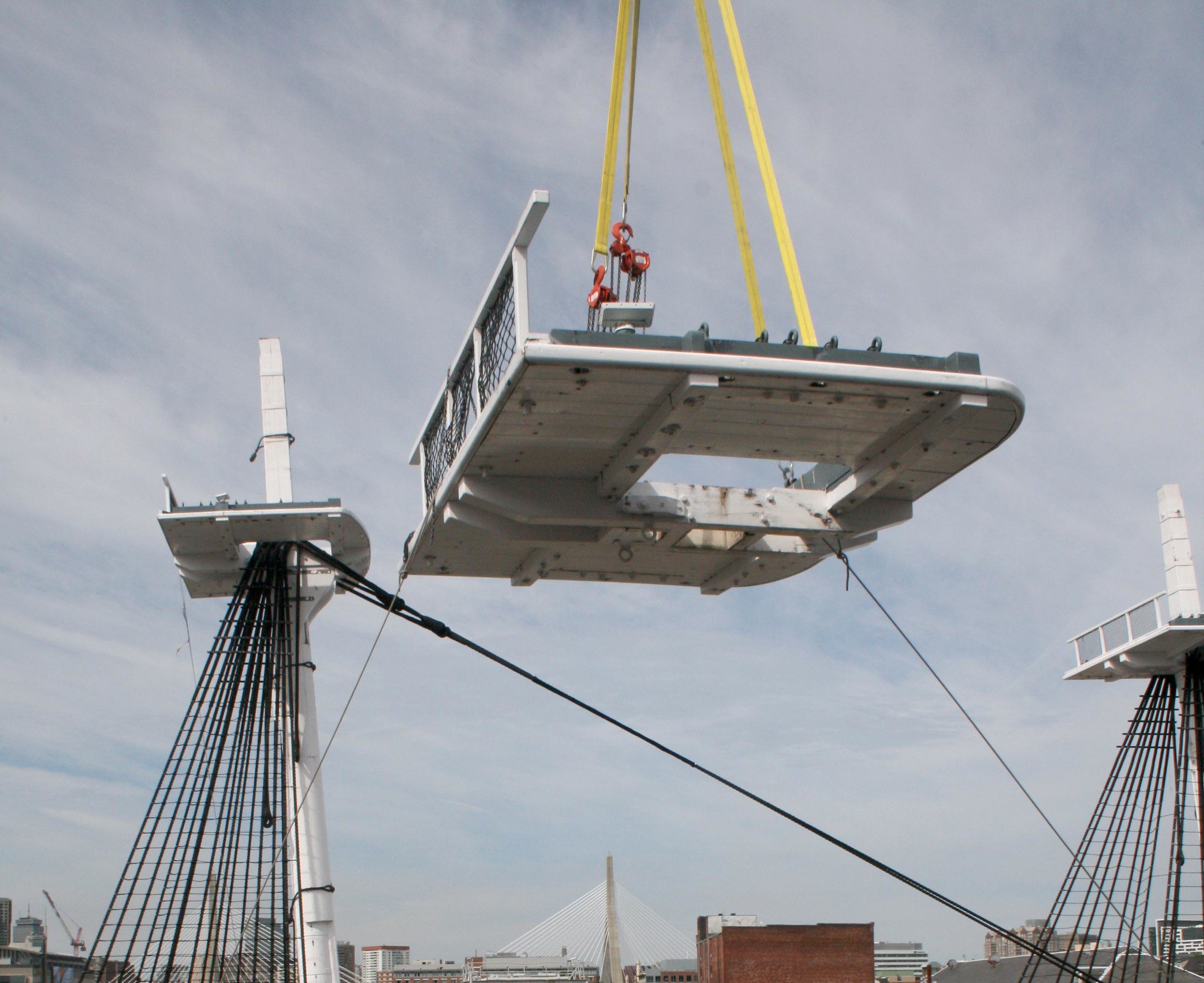
About the mizzen platform, I assume you mean the fighting top on the mizzen mast. If so, here are a few images of the platform where you can count the number of planks. I hope this helps. Jon


-
I hope mine look as good when I make the capstan. Based on yours and the the photo of the actual capstan, I might make the whelps a bit narrower with a lighter stain. However, I don't know if I can come close to your beautiful brass work with the tools I have. Nice work! Jon
-
USS Constitution by mtbediz - 1:76
JSGerson replied to mtbediz's topic in - Build logs for subjects built 1751 - 1800
Peter, didn't your MS kit come supplied with the grommets? Mine did. If yours didn't, you should be able to get a free replacement from Model Expo. Jon -
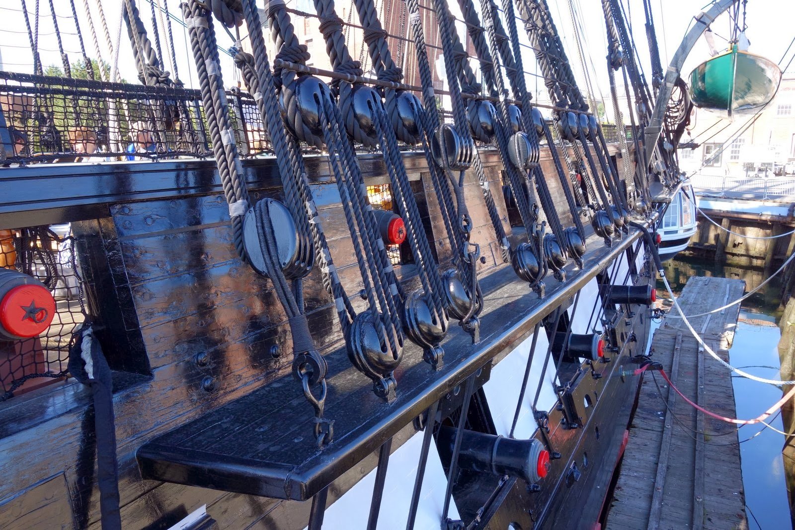
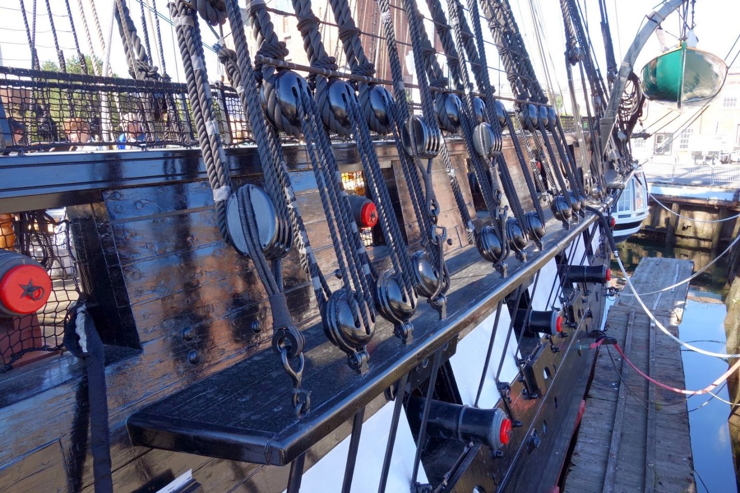
Yes, a very impressive service record. I never got any further than 3rd year Army ROTC while in college, when I was released from the program for medical reasons in 1969. But that's another story. Up to now, I have not looked too deeply into the deadeyes yet as I have not gotten that far in my build. (In case you haven't noticed, I'm very slow). So, I took a look at the real ship's hardware and discovered that for the lower deadeyes, the wire is not twisted, but doubled. It's a loop that goes around the deadeye and is bolted to the chainplate from both sides of the loop. At your 1:96 scale, a single larger gauge wire, twisted just at the meeting point at the bottom of the deadeye might be easier to do and would look more real than the twisted wire going around the deadeye. Jon
-
Bob's practicum is a wonderful guide and I wouldn't have started the Constitution without it, but it does leaves something to be desired. If you check, he did not even come close to finishing his model. He only did enough to show you how he did certain things. I am using Mr. Hunt's practicum, but only as a guide. I learned to do that after I followed his practicum for the Rattlesnake. At first, I followed it verbatim, slowly I noticed some minor omissions and errors. I learned to follow other builders' logs and compare what they did versus what Bob did in his practicum and then chose the most appropriate path for my skills and goals. As for the soldering, what method are you using? When I solder brass or copper, I use silver solder (both paste & "wire") and a torch as oppose to electrical solder and soldering iron/gun. I haven't had too many problems provided I made a proper jig to hold the pieces to be soldered in place. Pictures would help to illustrate the problems you are having. Jon
-
That will work. Jon
-
I'll keep that in mind, thanks Jon
-
The wheels turned out great! I hope I can do the same when I get to them. Jon
-
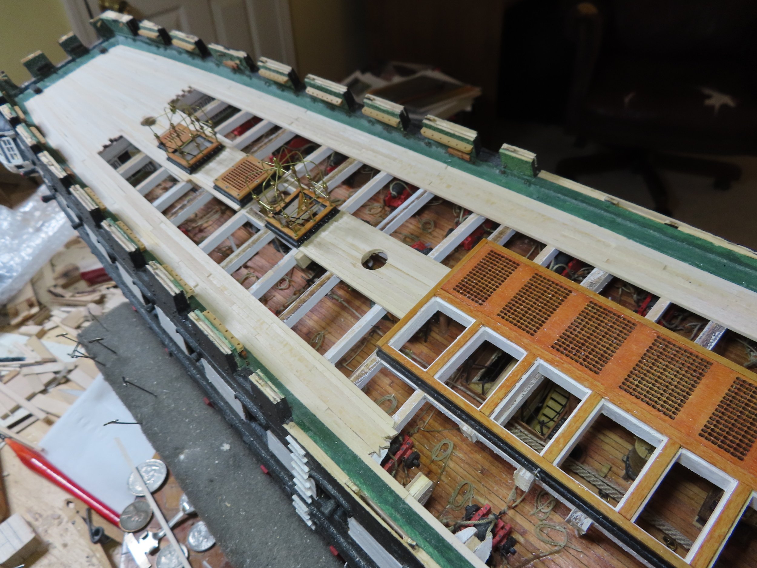
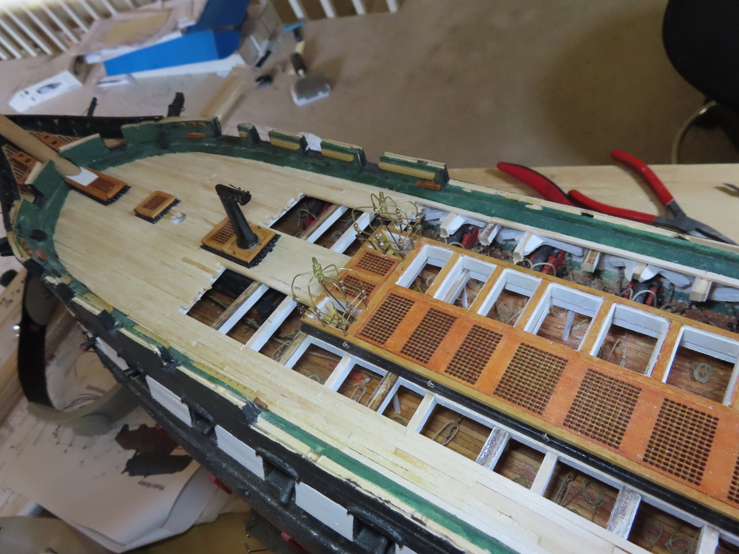
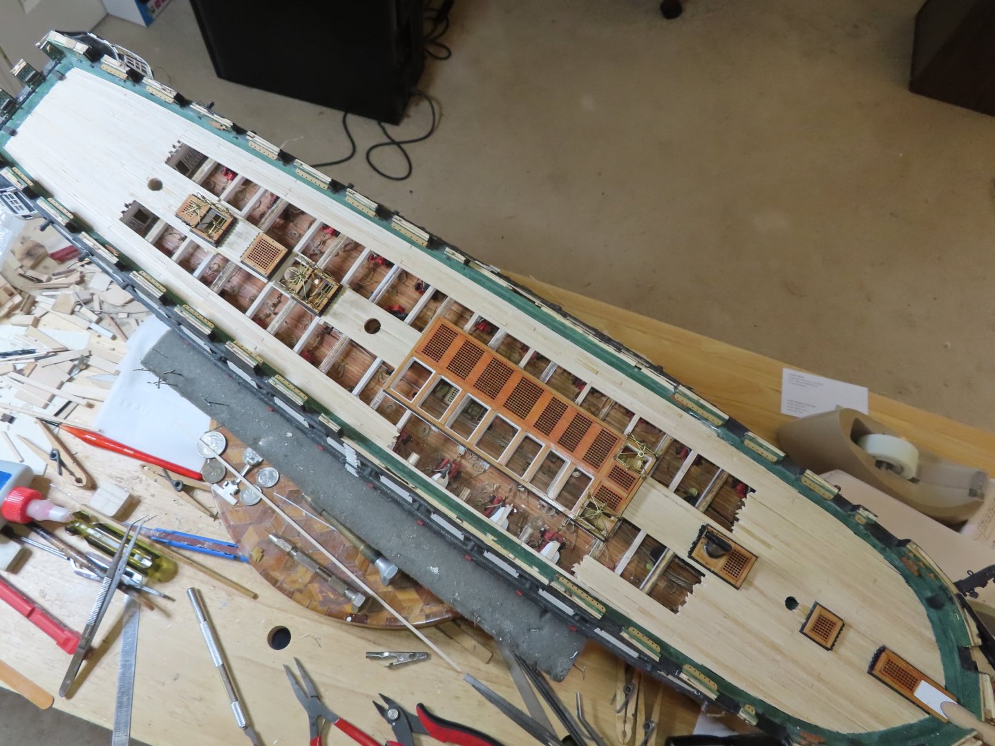
Peter: When I planked the gun deck, I started from the center and worked to the edges because I wanted to ensure the planking to look symmetrical. Any inconsistences would be at the waterways and would not be visible due the guns and visual access. On the spar deck, I also started from the center for the same reasons. However, at the stern, the planks taper to match the narrowing at the transom and curve following the shape of the bulwarks. I wanted clean looking planks especially at the waterways due to their high visibility, so I also planked from the water waters inward. Following the method from the practicum, the planks were tapered from full width from the last hatchway to half their width at the transom. That worked pretty well. As the two planked areas approached each other, I had to make some minor adjustments due to my workmanship and subtle differences in the supplied plank widths. For the bow, once more, I started from the center to ensure symmetry. This time the planks did not taper, but the planks bordering on the waterway had to be custom fitted as they intersected the bow curve. Once more for their visibility, I started the planking from the waterways inward to ensure proper fit. As the two planking areas approached each other, I could see that some planks had to be narrowed a bit to ensure the last plank to fill the gap between the two areas was the proper width. Gregg: The bowsprit dowel has not been shaped other than the base to fit into the square hole in the bulkhead. It is not glued into place. It does however slide into its seat easier enough when I move it in and out of the model. All the mast holes have been tested to accept their respective dowel pieces at their proper rake angles. The mast seating and rake angles were set when I was adding the structure elements to support the spar deck. As for staining the deck, I’ve made some initial tests of different stains and combinations but have not yet taken the plunge and committed myself yet. Jon
-
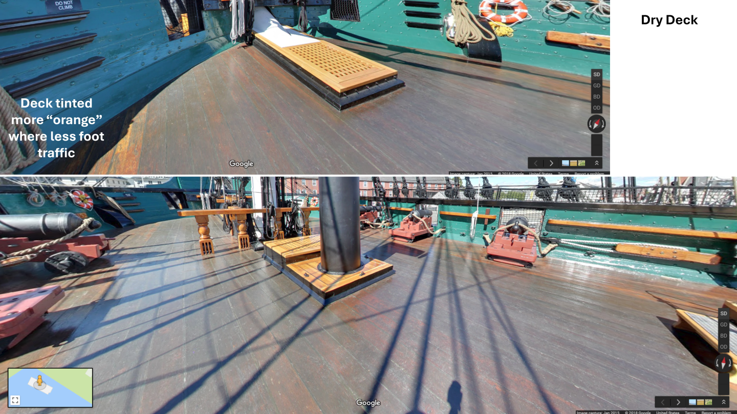
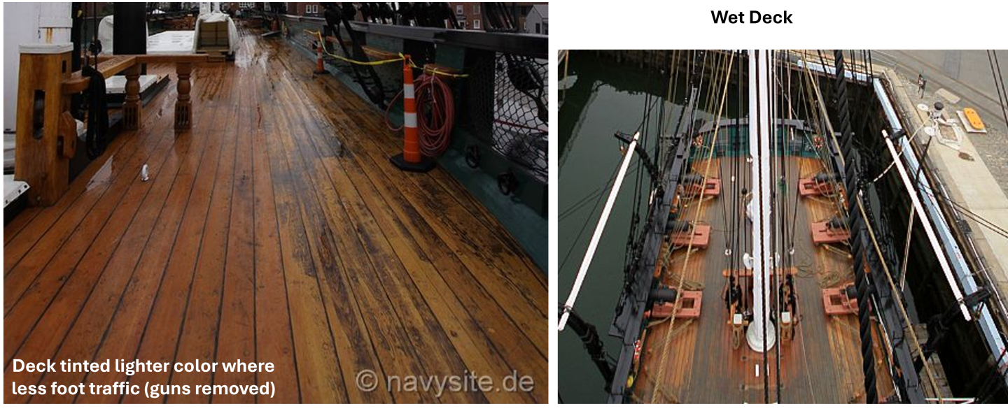
Obviously, my color scheme will be based on a dry deck. On a working ship, however, I would assume the deck would look different because the sailors would periodically swab the deck and scrub with holystones, saltwater and sand. Also, because of the cut away areas coincides within the high traffic areas, a lot of the brownish gray areas won’t be shown on the model. There is one last area that still needs to be planked, the small area around the spar deck capstan. I left that open till I at least fabricate the capstan base. I don’t know yet if I need to plank around the base or if I can plank under it. So, in keeping true with one of Murphy’s Laws, “No matter what you have to do, you must do something else first,” before I can install the captain’s skylight, I must at least sand the planks, prepare for the capstan, and stain the deck.
-
As I mentioned in an earlier post, the reason I had to plank the spar deck at this point was so I could install the captain’s skylight. Well, that will have to wait a bit more as I must sand and stain the spar deck first. And this brings up the question: What color is the spar deck? Well, it depends on several factors like whether the deck is dry or wet, was it sunny or cloudy when the photo was taken, is it a high foot traffic area (think tourists) or not. The main thing I noticed is there are two distinct color zones Low traffic orange tint - The area of the guns from the waterway to the end of the gun carriage and some spots along the centerline of the deck High traffic brown/gray - The public area for tourists. They tend to deposit dirt from their footwear, soiling up the walked area of the deck.
-
Unlike the stern, the 3/32” x 1/32” planks are not tapered as they approach the bow. The planks remain straight and those bordering the waterways were customed fitted into the curving bow. I planked the bow in the same manner as I did the stern, from the waterways inward and from the center outward. It did not surprise me, as the planking approached each other and as open space narrowed, I had to taper the widths a bit of some of the planks to ensure a proper fit when they merged.


-
That was beautifully done! Jon
-
The wheels look like a fun little project, so I'm saving them as my incentive and "reward" to complete the spar decking and the carronades first. I've also got to fabricate the spar capstan too. Jon
-
As you may know from reading my blog, I purchased two Syren ship's wheels a number of years ago in anticipation to replacing the kit's. Those kit metal wheels you painted look really good. What technique and color did you use? It's nice to know that if I screw up, I have a fall back option. I still have a ways to go before I can start assembling them, so it looks like I'll be following your lead. Jon
-
Out of curiosity, why did you cut the filler block such you had to mill out the notches in the top half blocks? If you had made the top half blocks thinner and the bottom half blocks thicker, you could have used your scroll saw to cut out the notches. The end product would have been identical, just simpler. In any case, you did a nice job. Jon
-
Beautiful!! Jon
-
Looking good. Gregg Jon
-
That's one handsome looking hull Jon