

michael101
-
Posts
441 -
Joined
-
Last visited
Content Type
Profiles
Forums
Gallery
Events
Posts posted by michael101
-
-
9 hours ago, mtaylor said:
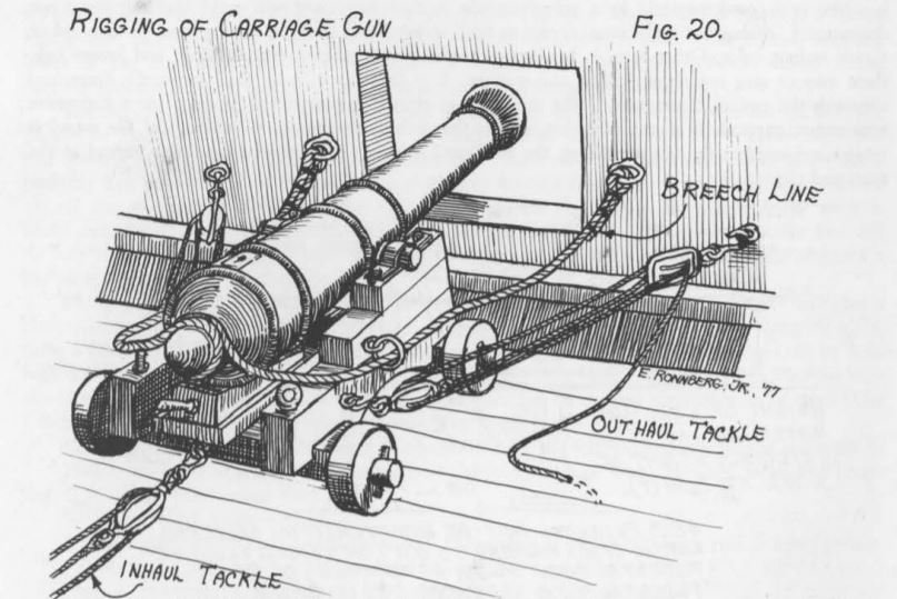
To "rotate" the cannons there was a set of "training/outhaul tackle" on each gun. Most models only show the basic one for recoil. The training tackle had pulleys and they also used a handspike to move the rear of the gun for training. The outhaul could be used for training. On some ships, there was an extra eyebolt on each side further from cannon to make training easier.
Thank you !
its very interesting !!
-
25 minutes ago, Morgan said:
Michael,
In practice the cannons could be moved several degrees from centre so they could in theory, and subject to the curvature of the hull / width of the gunport, all fire at 90 degrees to the ship, but I think this would look wrong on the model and you should, in my opinion, go with 90 degrees to the hull at each gunport location, as per the real ship has them displayed.
Gary
Thank you Gary I have think about that but I wasn’t sure if the cannons can be moved to the sides because the Wheels are directed forward so how did they change the degrees ?
-
-Hello there ,
I am bout to drill the gun ports holes on my HMS Victory but I’m not sure about the position of the cannons
in the bow the gun ports getting the same curve of the ship so the big question is if to drill the hole for the dummy barrel parallel to the cannons of the middle or maybe I need to drill it 90 degrees from the gun port it means that the cannon in the bow will not be parallel to the same line of the cannons in the middle
in the sheets of the caldercraft the cannons looks all parallel the cannon in the bow and the cannon in the middle they are the same
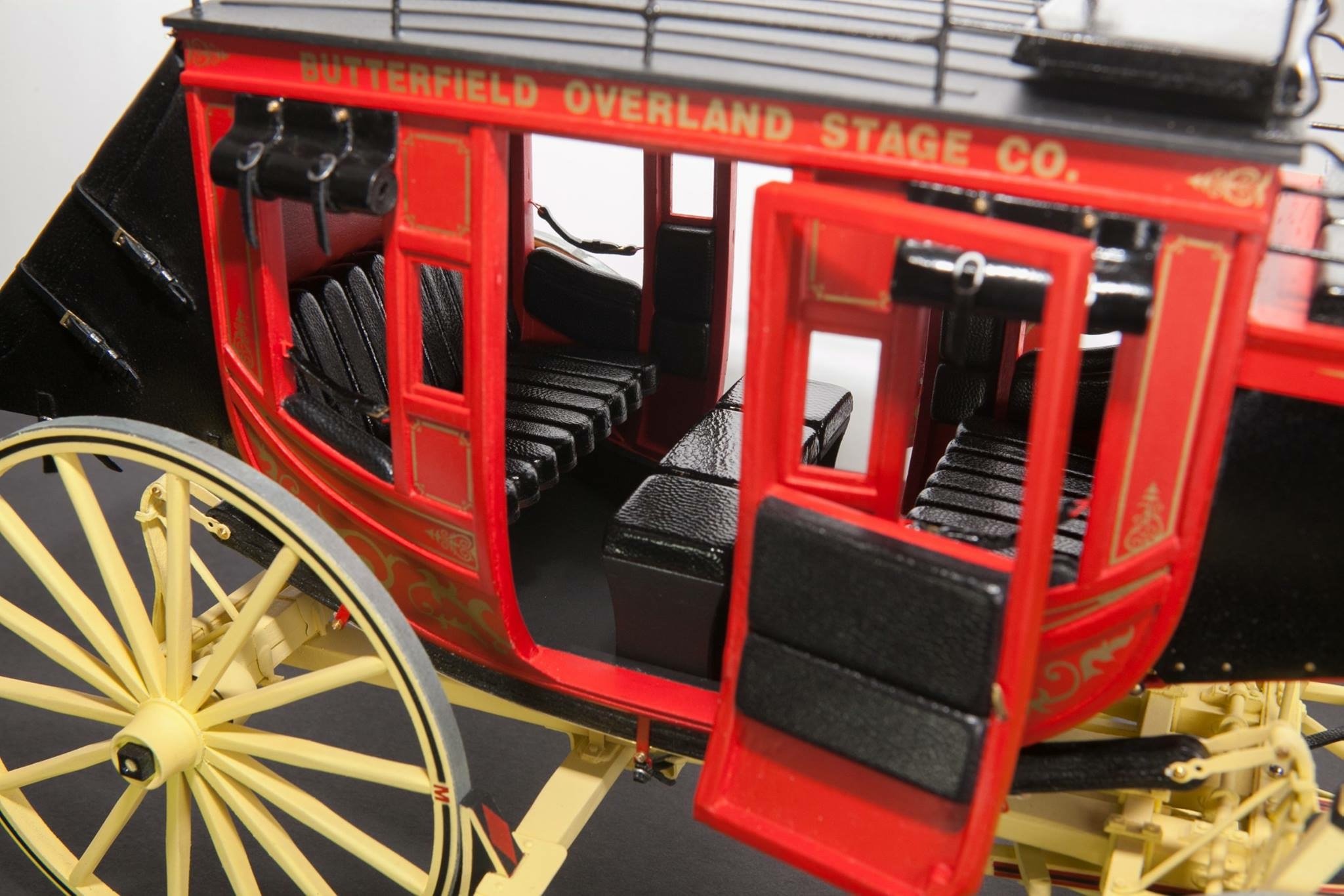
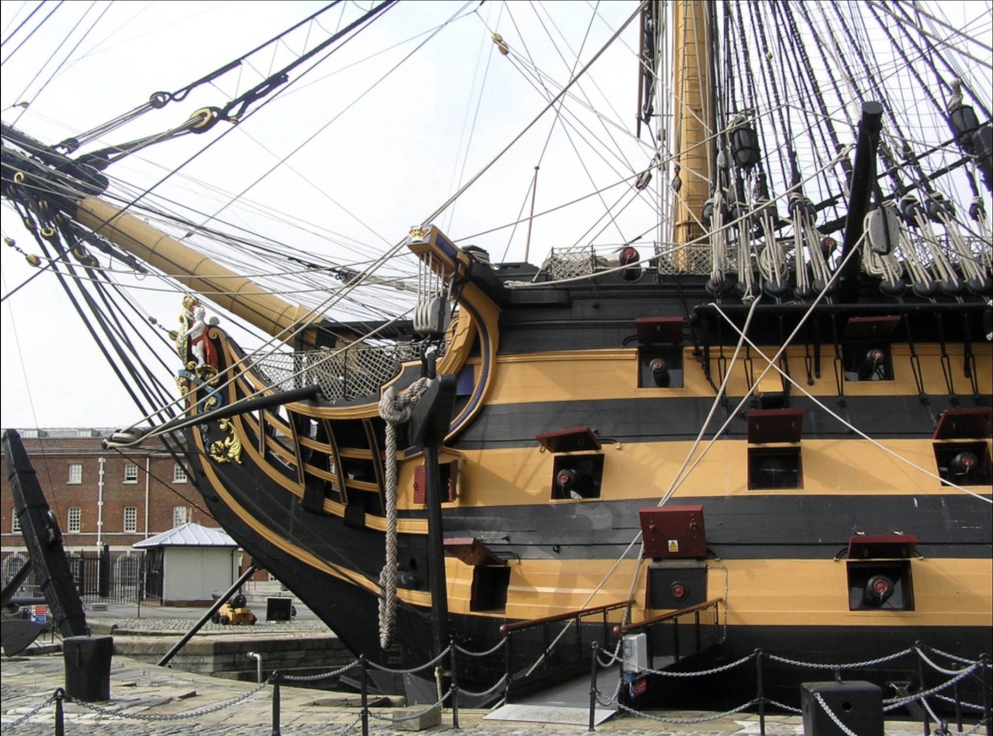
also you can see here a picture from the book anatomy of the ship that all the cannons they are in the same angle
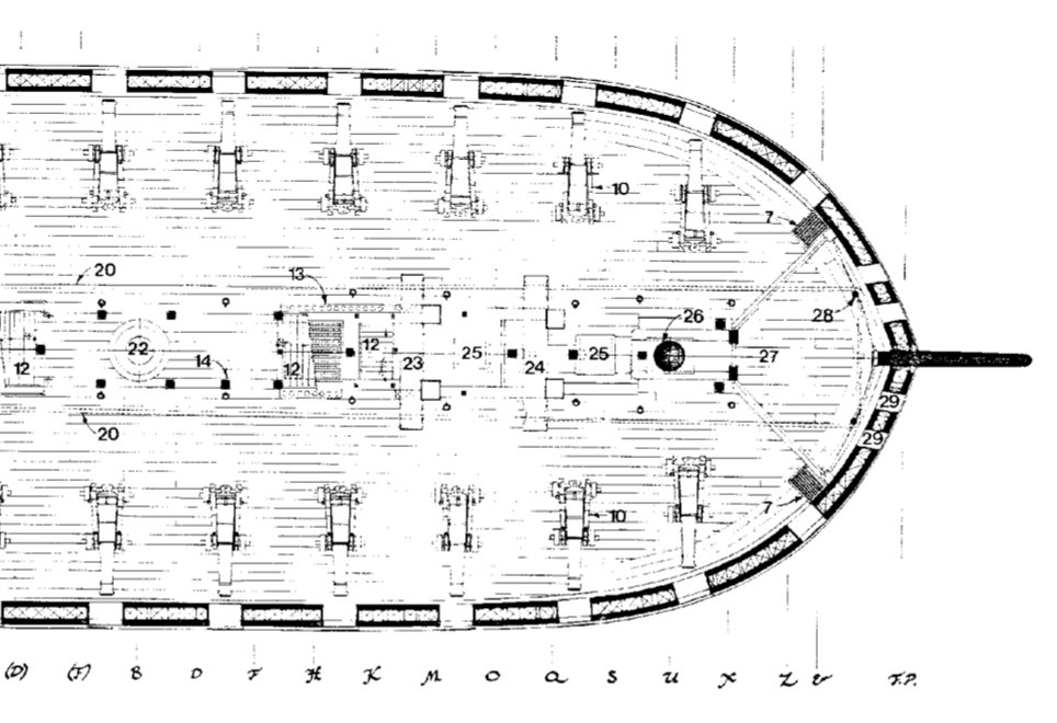
but in the real ship it looks like the angle is changing in the bow and the cannon gettin 90 degrees from the curve gun port !

So about the bow I think we have the answerbut I have the same question about the stern there is also a curve in the ship and I’m not sure about the cannons , in the sheets of caldercraft and also in the book of anatomy of the ship ,they looks parallel to the cannons in the middle
but I can’t take reference from the real ship because they removed the cannons from the gun ports in this section of the ship
so I’m not sure what to do,
if you have any proof about the position of this cannon in the stern I will be more than happy to hear that
Best regards
Michael.
-
Its always a pleasure to watch your work !
Just beautiful !!!!
-
-
Thank you Very much !! Im glad you like my work ,
to be honest it took me long time to do it i took each plank as a project
i think the secret for getting proud of your work its to do part by part plank by plank as a project by itself without to think when im going to move to the next plank ...
just to do your work without rushing at all , its an hobby not a business , just relax and put all your mind on the little thing that you doing and think about that as a project by itself
BTW i saw your Vasa and it looks amazing ! So im sure your second plank on your current model will be perfect !
Best regards ,Michael.
- Landlubber Mike, Helli, EJ_L and 1 other
-
 4
4
-
4 minutes ago, md1400cs said:
Michael,
BTW you hull planking work is also so perfect. I also like your method for fitting in the keel - Super nice work.
Are you going to hide everything with copper?
Thank you for your kind words
")
about the copper , I do not going to use copper plates at all ,
BTW on top of this planks going to be second plank (walnut)Michael.
-
-
-
-
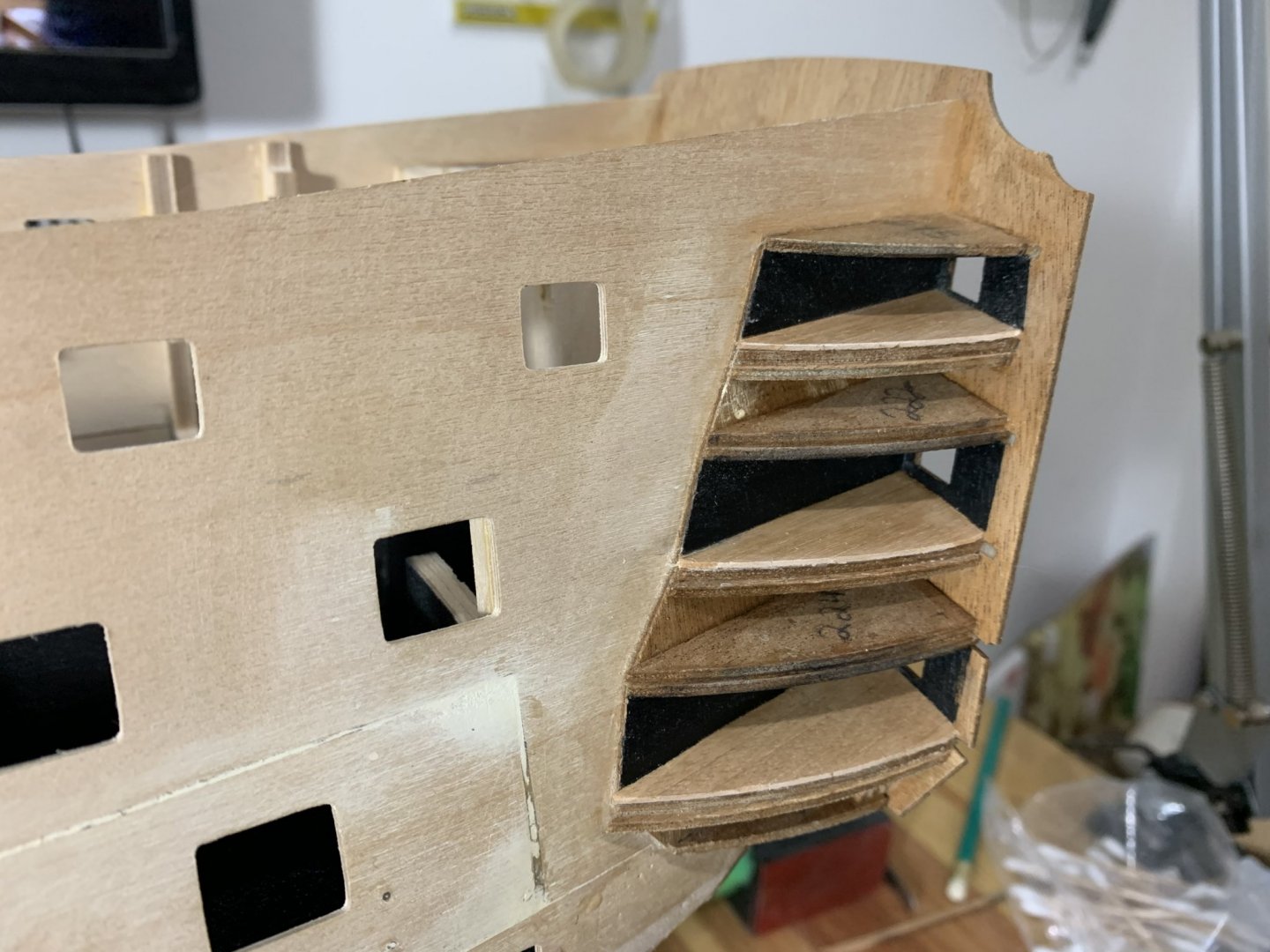
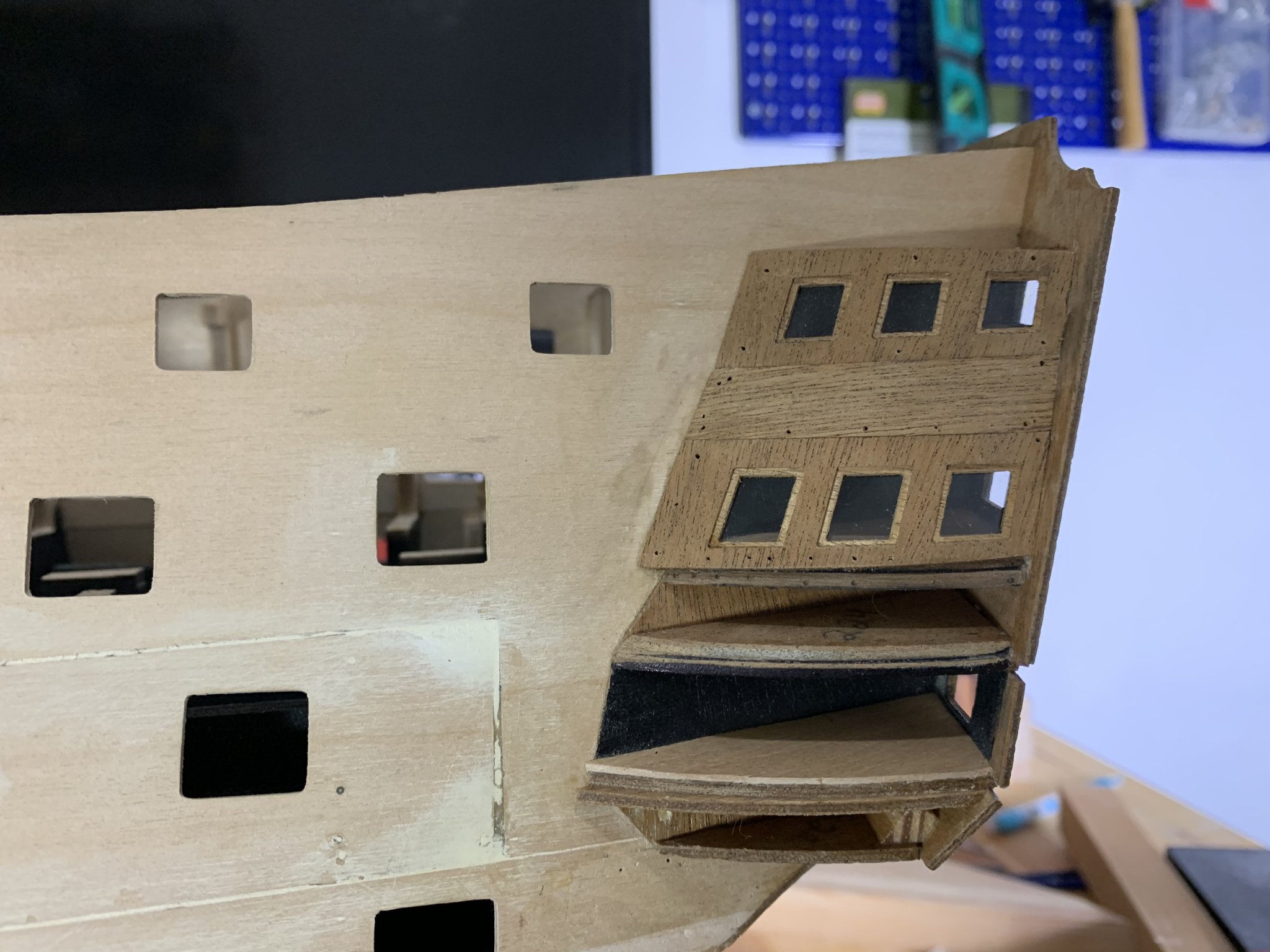
Hello friends
on the last few months I was working on the gallery so here is an update
maybe it will look a small thing but it took me a lot (more than a lot 😀) to finish this aria
I will show step by step to help other builders who going to reach this step....
but first of all I have to say a big thanks to Robert (has the nickname Berto in this forum)
Who helped me understand all the future issues that could be with the gallery if I followed the instructions I will talk about them later ...
but after understand the problems I had to think a lot to solve problem by problem...
So lets get started
first of all I had to make the deck before putting the windows and painting black the background (in the instructions it not tell you nothing about to install any deck behind the windows and bento told me that must make this deck and do it before installing the windows ...)
About the glazing
There is a real problem to glue the plastic film on the wood for a several reasons
Any kind of glue in the future will get off because of the nature of the wood due to the temperature of the season...
The only good glue for this method will be epoxy but its not ideal .. you can dirt the film easily...
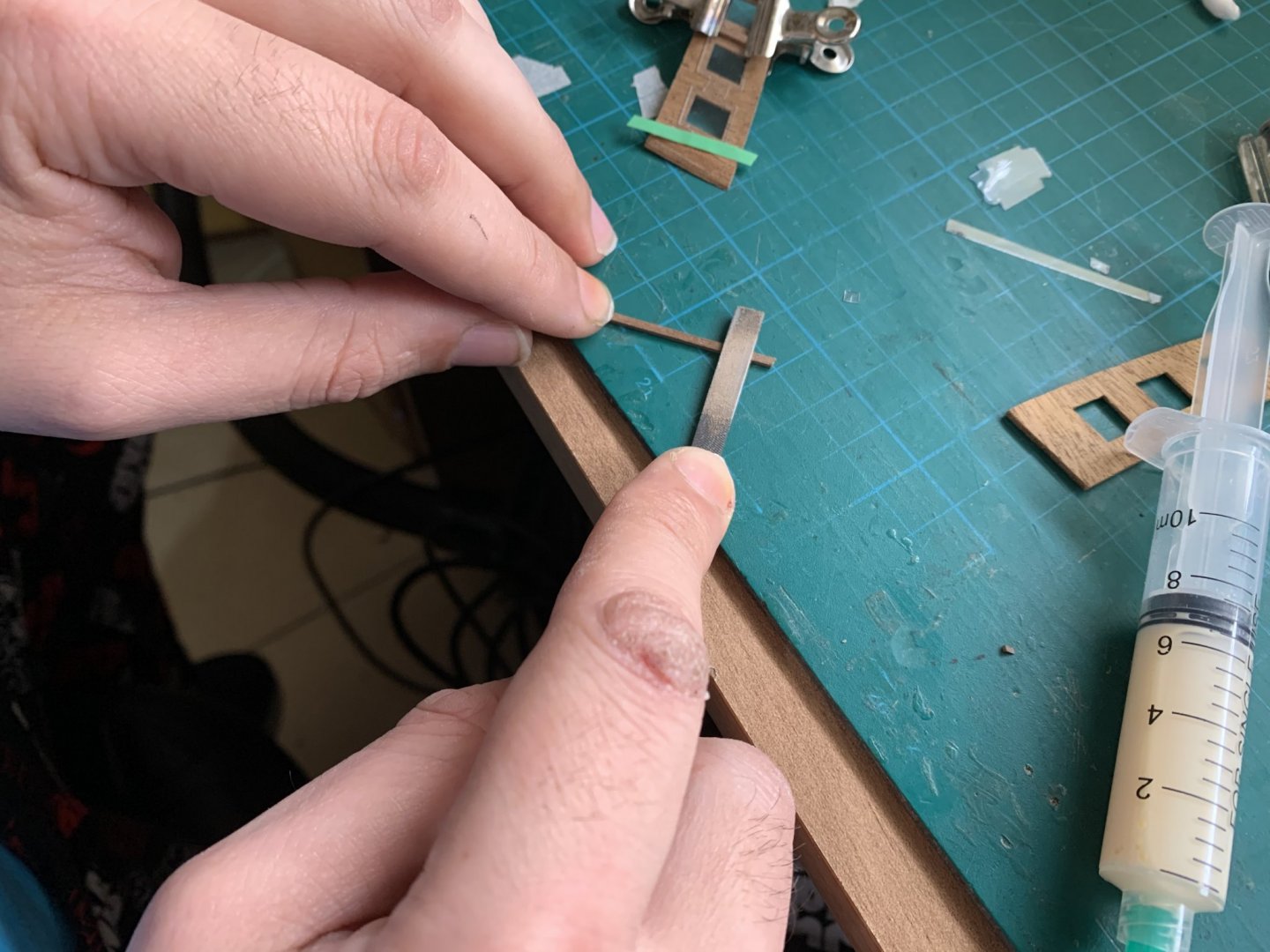
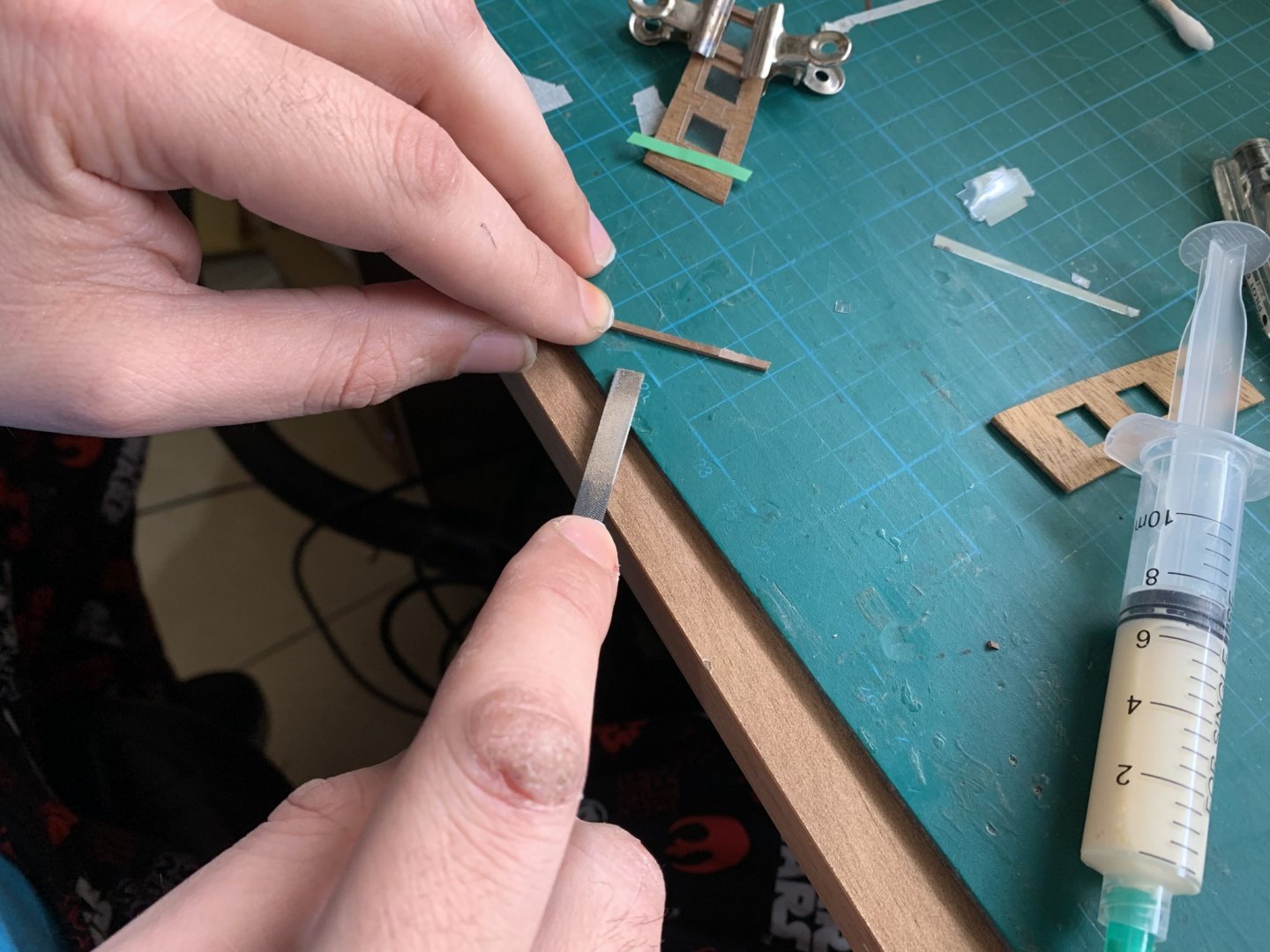
So after a lot of thinking i decide to use this method :
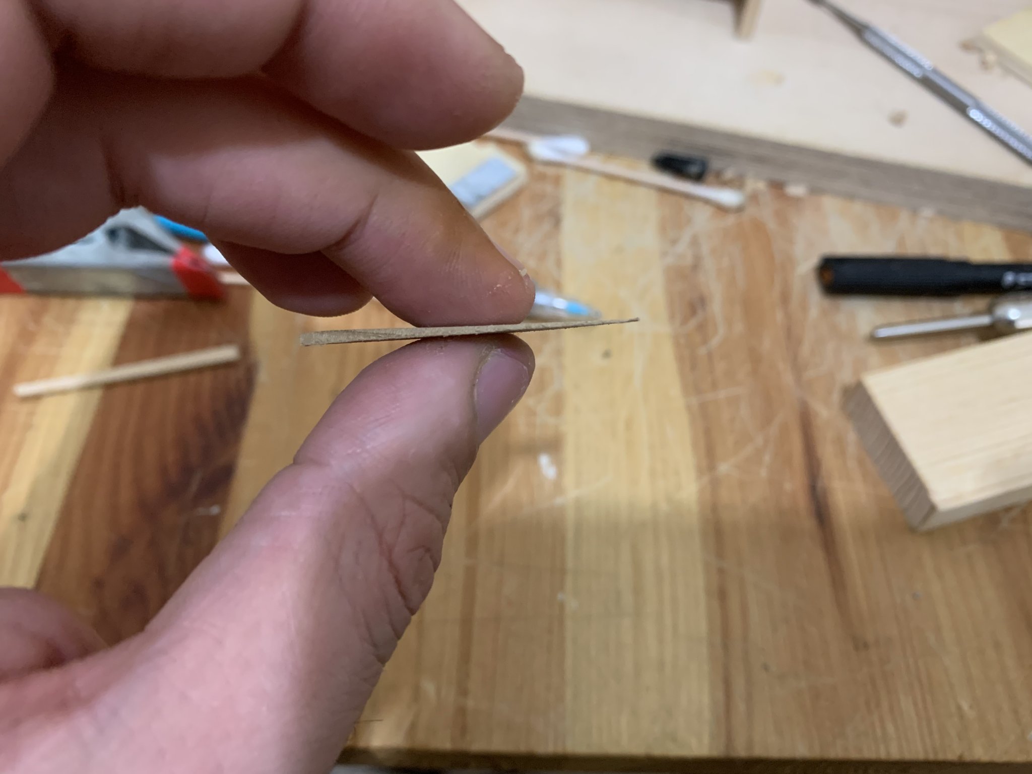
First i made the templet of the film with a slots up and down between the windows
And then i have used a timber of 1.5 mm by making a slot in the middle that will fit the exact thickens of the film
Then i glue it in place in the back of the windows templet
here is the steps and the result :
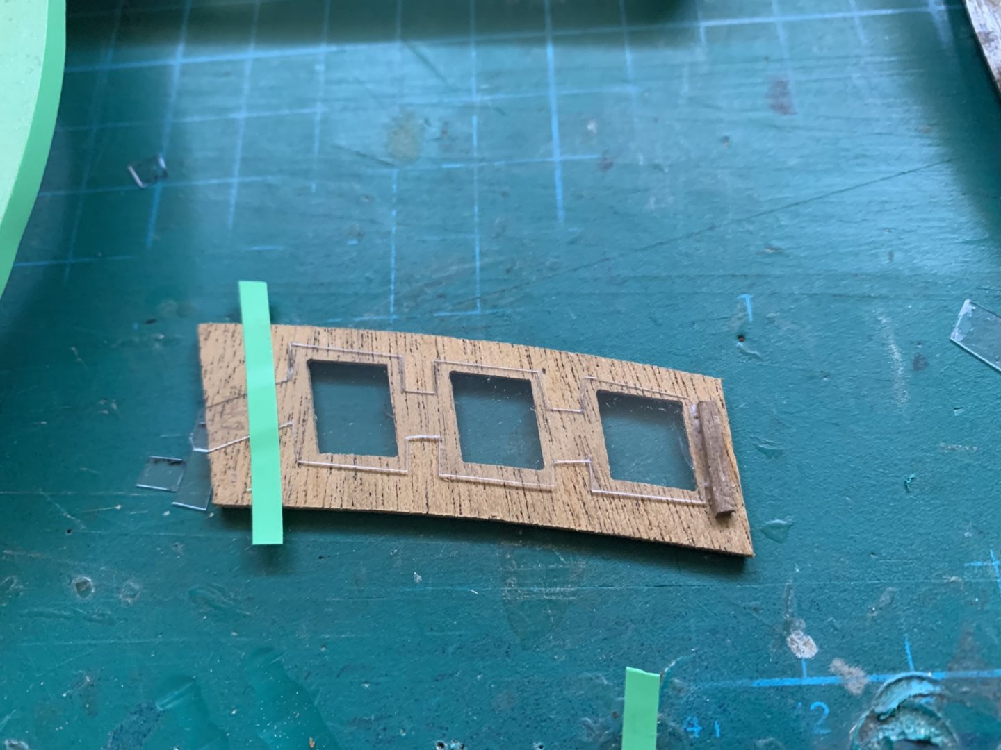
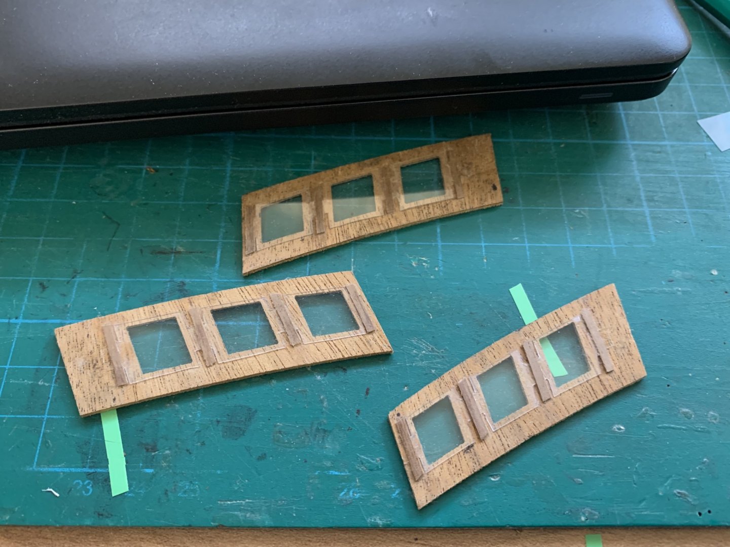
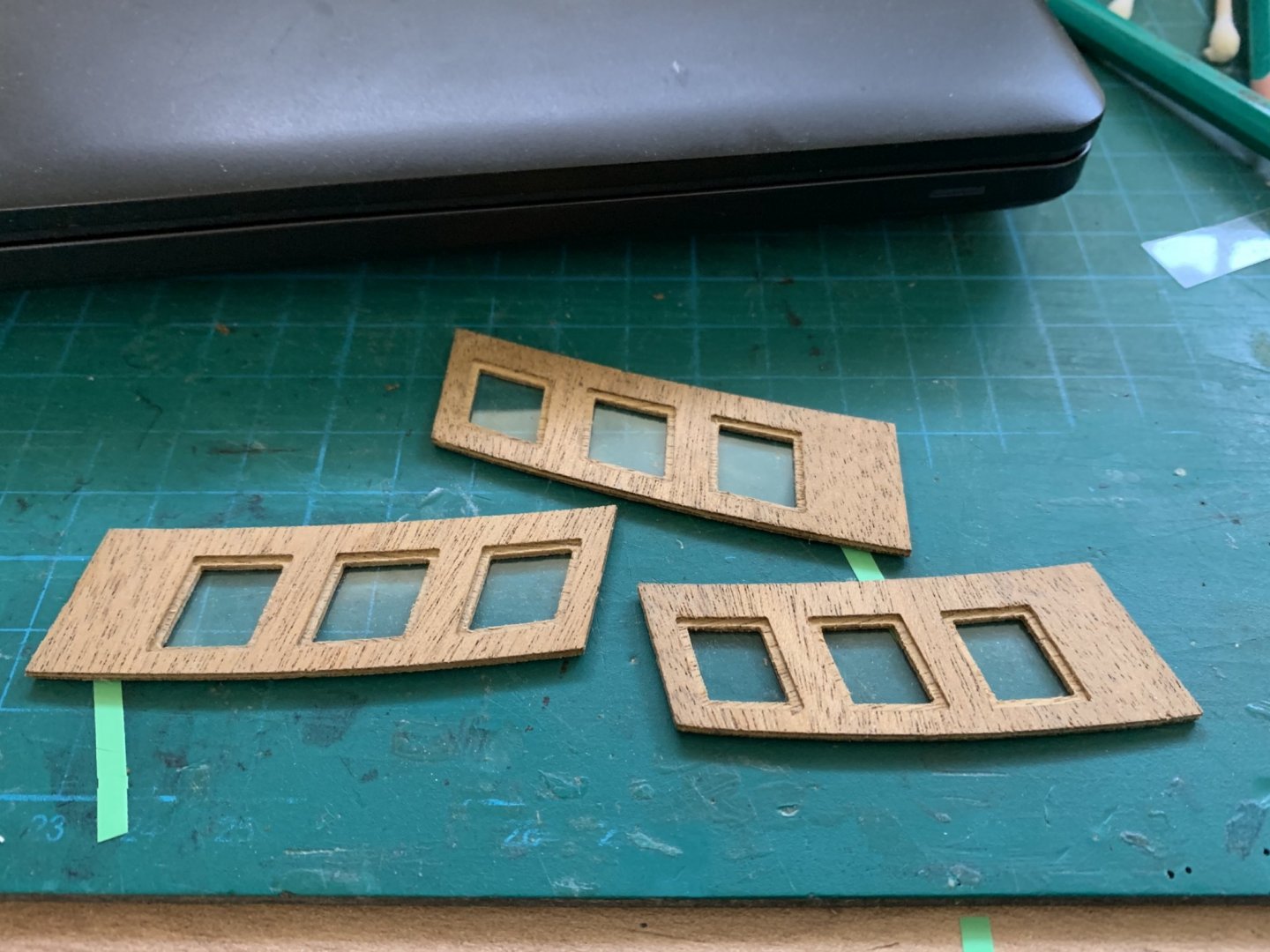
I have to say that the skins (patterns ) are not matching each other at all !!!! you have to be careful to make the exact shape for making smooth match !!!!
here is a picture of the process (don't worry about the hols I will cover them at the end
") )
)

now the big or maybe the huge problem!!! that I had to -

and have to say again thanks to Robert for warned me about this issue !
there is a 2 patterns of the back gallery the one that already installed no. 374
and the back pattern (no. 375 )who will install on the pattern no.374
so the problem is that the second pattern not seat exact on the first one. you can see it clearly in this picture: (I merged both patterns in photoshop , the hard lines are the first pattern no.374 and the light lines are the second pattern no.375)
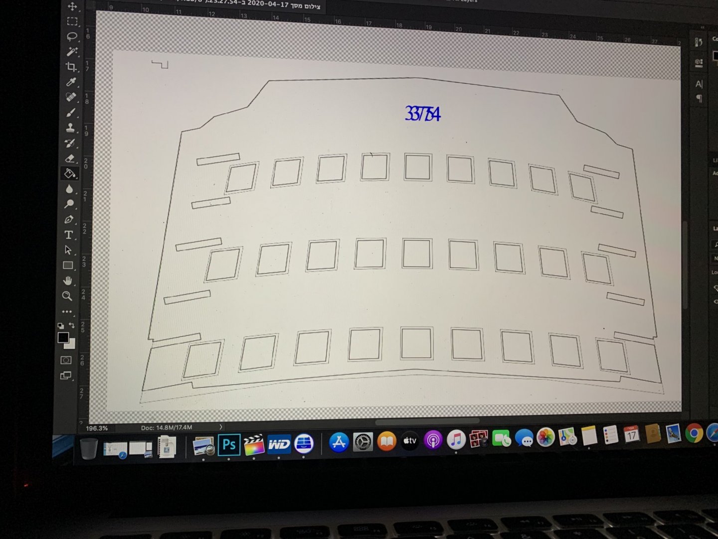
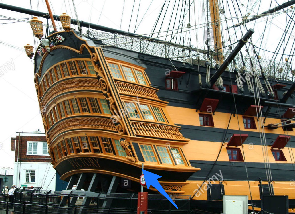
The big problem is that in the low line of the second pattern you will have to install a profile for all over the line and at the sides you have to install a profile how need to mach the corners of the back profile !
so if you will leave the last skin as is it will mach the corners of the first pattern and they are over (above) the corners of the second pattern!!!!
then the side profiles will never get mach with the back profile because they are above the back !
here is a picture of the profile (look at the blue arrow )
so After a long time of thoughts I got a solution ...
by the way I saw that problem in the others build logs but the builders came to the problem after they try to install the second pattern ...
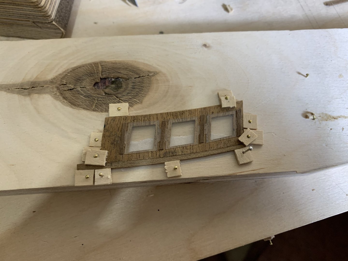
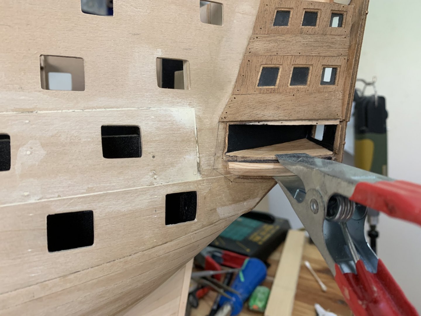
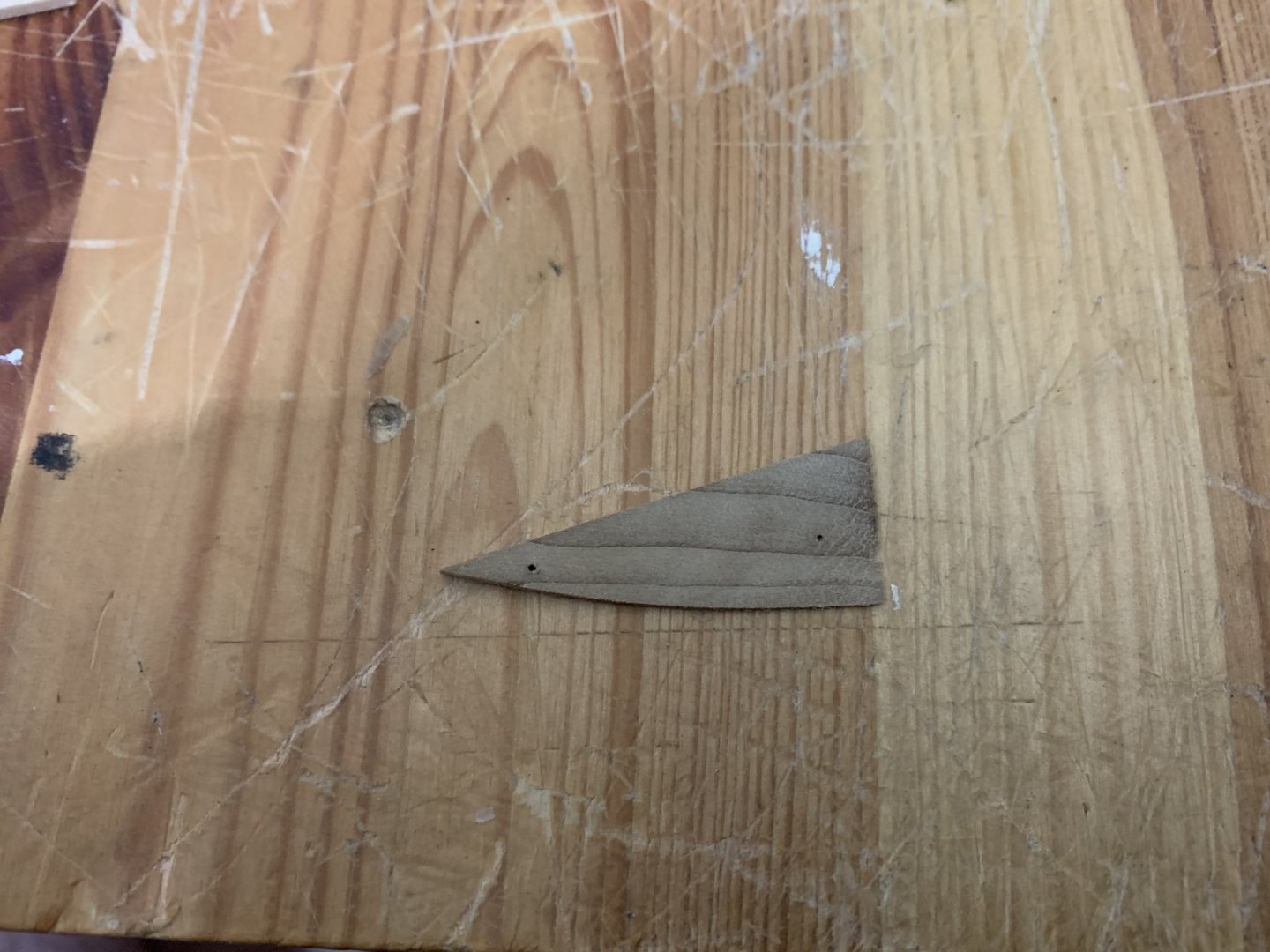
my solution was to add a wood to the last skin to get the exact cornet of the second back pattern no. 375
so I have install the second pattern temporary for taking the Lins of the corners .. then I made the extension of the last side windows pattern
BTH the space in one side of the skin its bigger than the other side so I had to cut the wood in angel ..
here is a picture in the middle of the process:
for the builders who going to work on this stage it recommended to make a block filler under the last skin because after you making the extension for the last side windows pattern you will lose the "bulkhead " the one before the last one !!
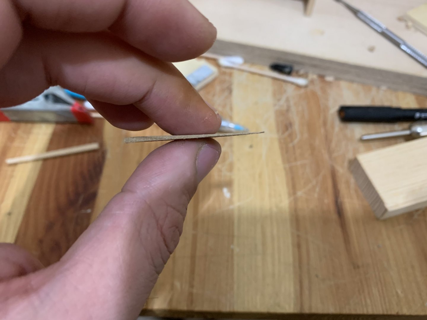
also I had to make one side of the last bulked thick than the other side in 1.5 mm for giving more Uniform space along the last skin so I made this wood extension:
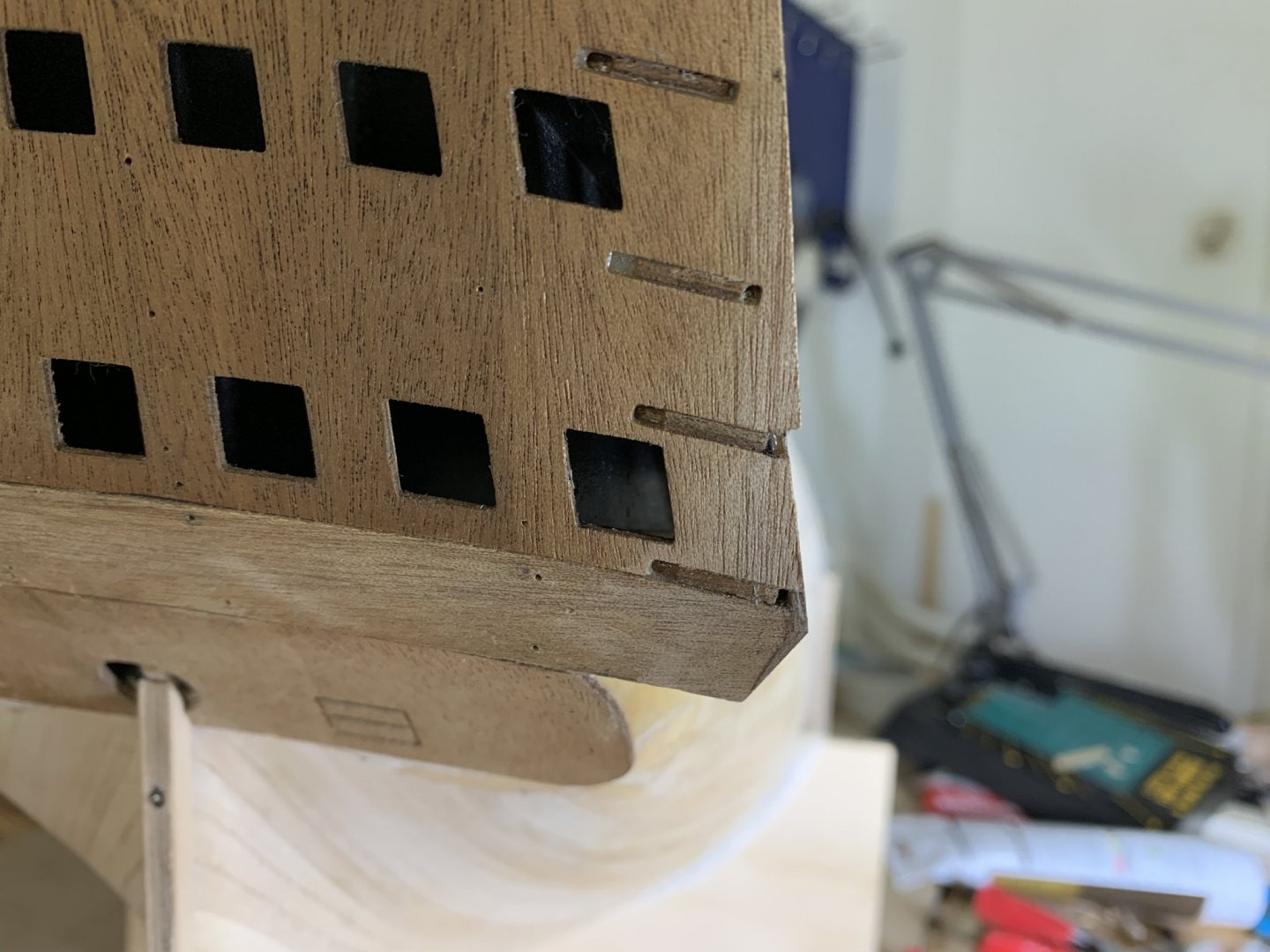
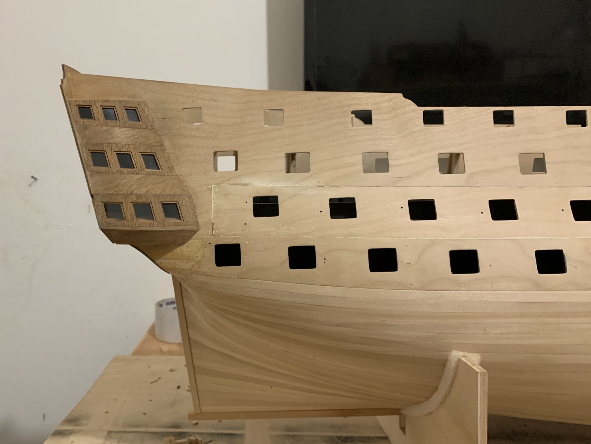
and here is the pictures of the final galley project (still need to term a bit the rest of wood of the last skin who going a bit down the line of the last bulkhead but I will do it when I will put the ship upside down on the stand ...)

and in the back :
hop this post will help other builders who came across this stage
Best regards
Michael.
-
You must make a clamps up and down for all over the keel , glue the bulkheads then put the clamps on make it straight ..
then use the method of mtaylor !
dont push any bulkhead just make the supports to be exact size between the bulkheads then glue the supports from out side ...
make sure not to press the bulkheads with the supports !
-
Hi
where exactly you have the warped ?
there is a solution for everything ! but need to know before is it in the middle ? bow ? stern?
take a picture ..
-
-
-
I think you not need any bulkheads or fillers ...
if the ship its a big scale just add supports from one bulkhead to the next ,
you can see what i have done in my Hms Victory
but when you putting the wood supports you must be sure that the keel its straight and the supports are exact without pressing the bulkheads ...
Best regards
Michael.
-
Hello there ,
im almost there.... almost going to work on the second planks of the Hms Victory..
i saw a lot of beautiful and symmetrical caulking for the hull planks in google for model ships ..
but i didnt found the methods for them ..
i will be more than happy if you will share with me your experience about how to caulk the planks (without The paper methods ..)
Best regards ,
Michael.
-
-
Hello there,
A few yers ago i bought some blades of 0.5 mm to my Proxxon table saw for germany they are the best blades i ever see ...
the point is, the hole of this blades its 10mm
and i cant use them for my byrnes tables saw...
but i saw that this site selling also blades of 13mm Hole
my question is if i can buy them for my byrnes t.s,
the byrnes t.s use blades with 1/2 in (12.7mm)
so the big question is if 0.3mm will make a problem..:
Best regards,
Michael.
btw here is the link for the german site:
https://knupfer.info/shop/index.php/deutsch/catalogsearch/result/?q=Sägen
-
Thank you all !
i have change the blade and everything working amazing !!!!!!!!!
now i can say its the best tool i have in my workshop !!!
- Canute, Ryland Craze, mtaylor and 2 others
-
5
-
-
Hello Thisthe
I dine talk about the blade slot , I took a reference from the channels of the sides I mean there is a channel on the aluminum board and I put the fence exactly flush with the slot of this channel I locked down the front lock then the back but still you can see in the back that the fence is not a straight line withe the back channel …
And about the miter of the 90 degrees I’m talking about the slots of the 90 it’s not exact 90 degrees you must do it by the manual screw and can’t trust the pin …
i have check the piece that with angle miter it says 91 degrees …
————-
Thank you Y.T I saw this video fue days ago
-
Hello there
i bought this saw last year and not had the chance to use the saw until now,
now after using the machine I notice that the fence it’s not a straight locking (if you putting the fence against the Channel in one side the. Fence will be flush with the Channel and in the other side it’s a bit out of the line )and also when cutting 90 degrees its not accurate to cut it exact 90 degrees ,it’s about 1degree out of the line (I have check it with caliber )have you had the same problem?
i hope I’m doing something wrong , if not I’m really Disappoint

—————————
im editing now my post and after changing the blade all works perfect !!!!!
its the best tool in my workshop!!!
i dont want to delete the post because maybe all the info below it can help other people🙂
-


Accurate Triangle metal square
in Modeling tools and Workshop Equipment
Posted
Hello friends
im looking for an accurate drafting triangle square in size of 12’’ [30cm] 90 degrees made of metal
but in each one when I’m looking at the reviews over the internet the said it’s not accurate …
can someone recommend about a very accurate one?
best regards,
Michael.