Louie da fly
-
Posts
7,993 -
Joined
-
Last visited
Content Type
Profiles
Forums
Gallery
Events
Everything posted by Louie da fly
-
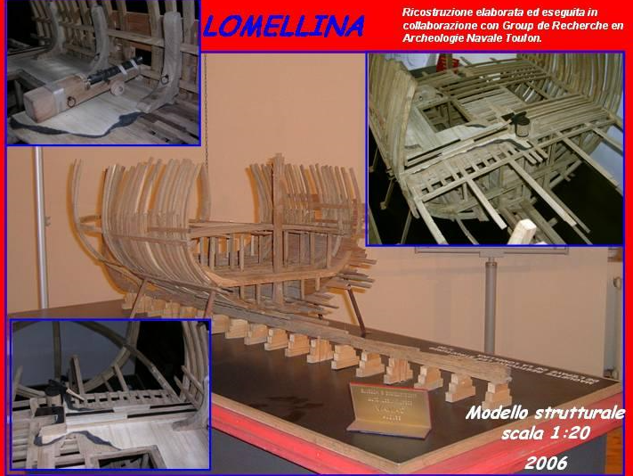
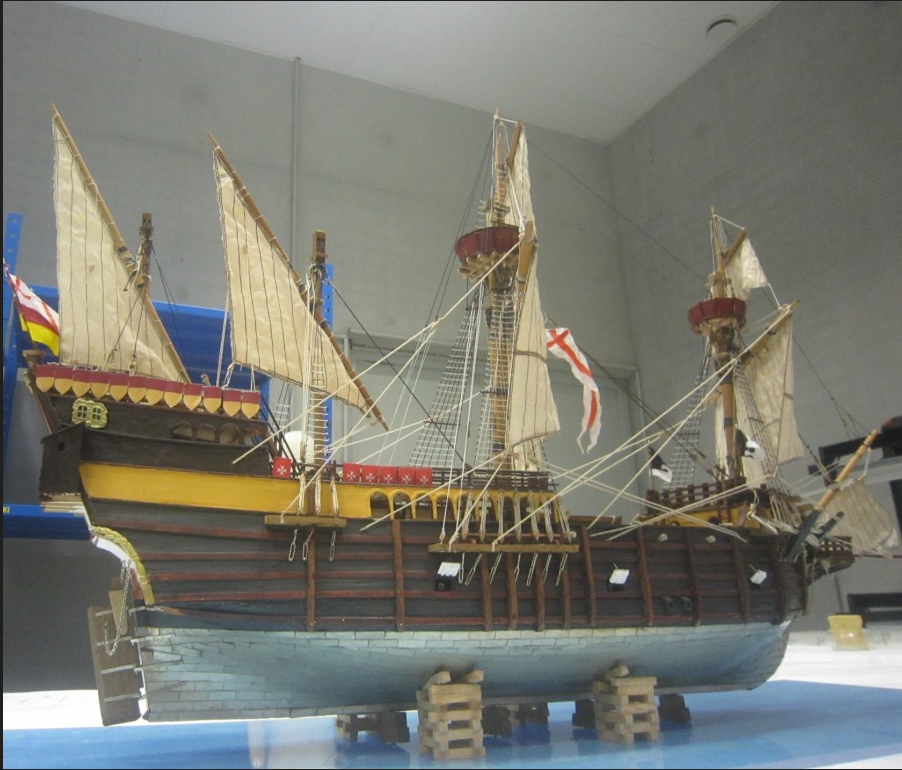
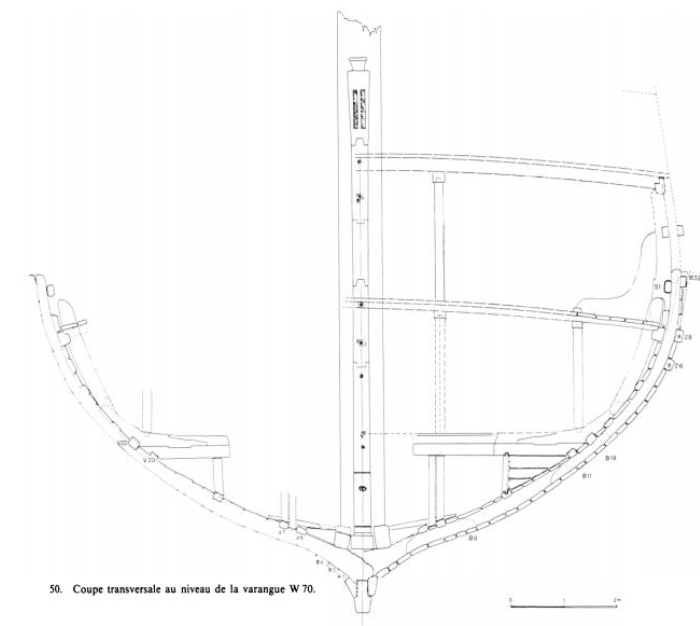
 Thanks everybody for the likes and comments. Just a quick point to start with. That diagram of the keel assembly wasn't done by me - it was from the published archaeological report, kindly sent to me by Dr Max Guérot, the leader of the archaeological expedition that uncovered the Lomellina, along with many many other reports and references to other wrecks that he sent me. He has been very generous and I'm very grateful indeed for all his selfless help. I've just emailed him to let him know I've finally started - it's a little embarrassing - it's been more than four years since we've been in contact and he'd probably given up on me. Anyhow, things are finally starting to move, albeit slowly. One thing I'm beginning to realise is that I'd been a little over-confident about how much of the ship survived to act as a reference for my reconstruction. There's certainly a lot less than, for example, the Mary Rose. Here's a model that was made of what does survive. But on the other hand, there's quite a bit to work with - we have a fair bit of the keel, quite a bit of framing and planking, part of the rudder, guns (with carriages!) and even a gunport lid, for heaven's sake! And lead sheathing on the underwater hull! No forecastle, unfortunately (dammit!) But I'm pretty confident I can get something worthwhile out of what's available and fill the gaps from contemporary images, particularly the superb Ursula Legend paintings by Carpaccio, dating to maybe a decade before the Lomellina was built. Venetian rather than Genoese, and I'm aware there were differences in construction between the ships of the two city-states, but in general, a good guide. Woodrat, I'll probably be availing myself of your generous offer of help with traduire, and yes, I'm planning on a round tuck - all carracks of this period seem to have them, and the theoretical reconstruction drawings from the dig show one - - and anyway, the earliest evidence for a flat stern on a carrack that I'm aware of is 1511. By the way, looking back at the manuscript illustration of the first Lomellina, above - I will only be taking from that what I believe to be relevant - it's of an earlier ship and the artist doesn't seem to have understood ships very well. I've been drawing the keel assembly based on the archaeological report, and to be honest I may have trouble duplicating the carpentry of the scarph joints at 1:100 - I'm just not that precise at woodwork. I expect I'll have to rationalise and simplify somewhat. And I'm not planning on duplicating every aspect of the vessel, particularly not the more complex inner construction details. That way lies madness. But it will certainly be more historically accurate for the period than the one that was made by a model-maker in the early 1990's supposedly showing how she was - maybe half a century too late, and wrong in so many ways. Steven
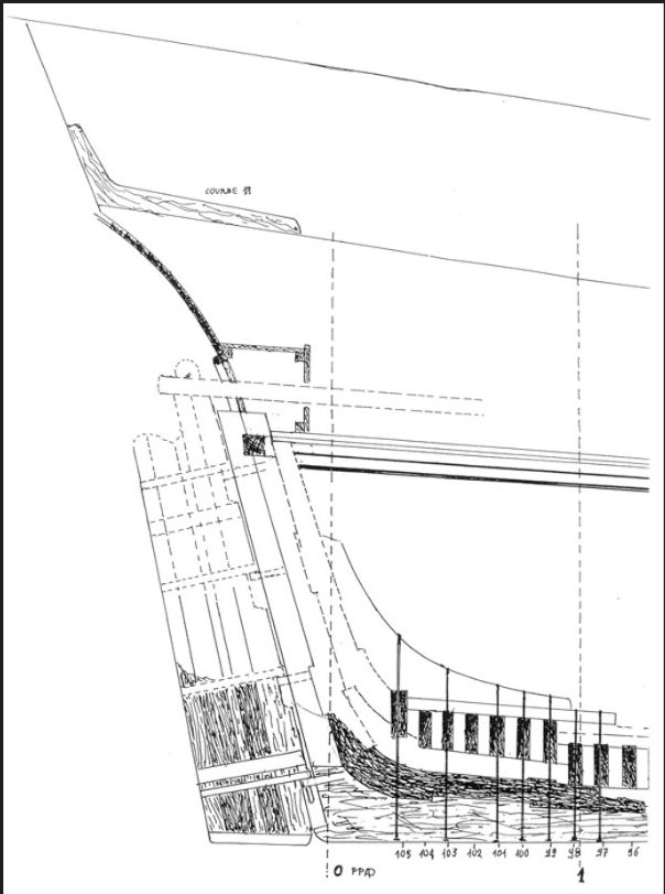

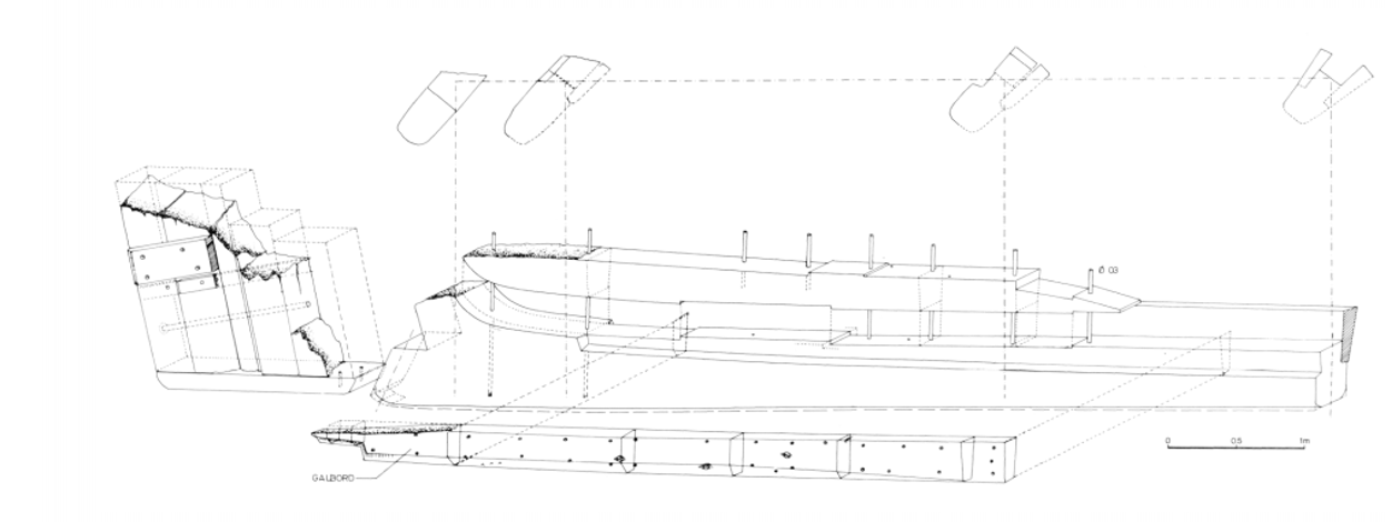
-
Well, I've made a beginning on drawing the hull, using the dimensions and diagrams in the original archaeological reports. Unfortunately for me, these are in French, and technical French at that. The main report, not including the Annex, is 162 pages long, though that does include things like the coins and pottery found on board, which doesn't concern me (except that these things helped the archaeologists to date the find). I used Google Translate to help, as my French is not up to the whole job, as well as an on-line French-English maritime dictionary that seems to be from the 19th century. But when you have words with several meanings - à means both 'at' and 'to', bâtiment means both 'building' and 'ship', pont means both 'bridge' and 'deck' . . . you see the problem. I'm struggling through it, and I've started drawing the surviving pieces of the keel, rudder, rising wood and garboard . . . It's going to take awhile, and as you can see by the picture of the surviving hull in the first post there'll have to be a fair bit of educated guesswork in supplying the (many) missing bits. Fortunately a fair bit of the theoretical work has already been carried out, so it's not as bad as it first appears. I have obtained the length of keel, overall length, width at the master frame and a few other worthwhile dimensions, which should help a lot. Steven
-
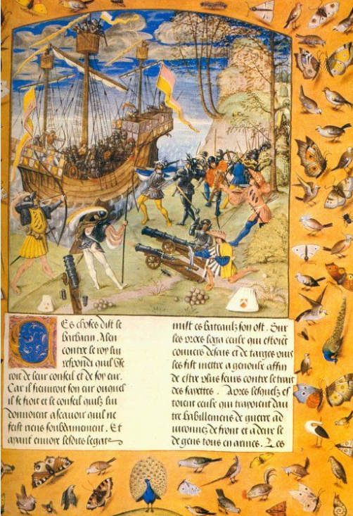
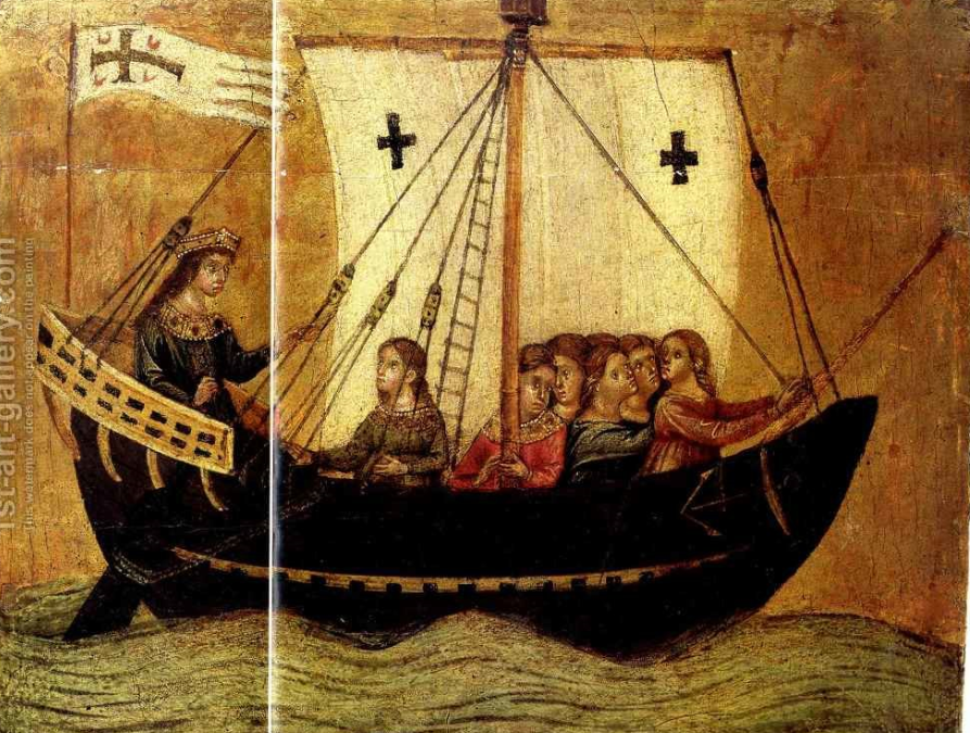
Interesting - Elisabetta is flying the banner of the Lomellini family, plus the red cross on white of Genoa. And if she was built in 1490, she would be 13 years or so old when the Lomellina was built. Steven
-
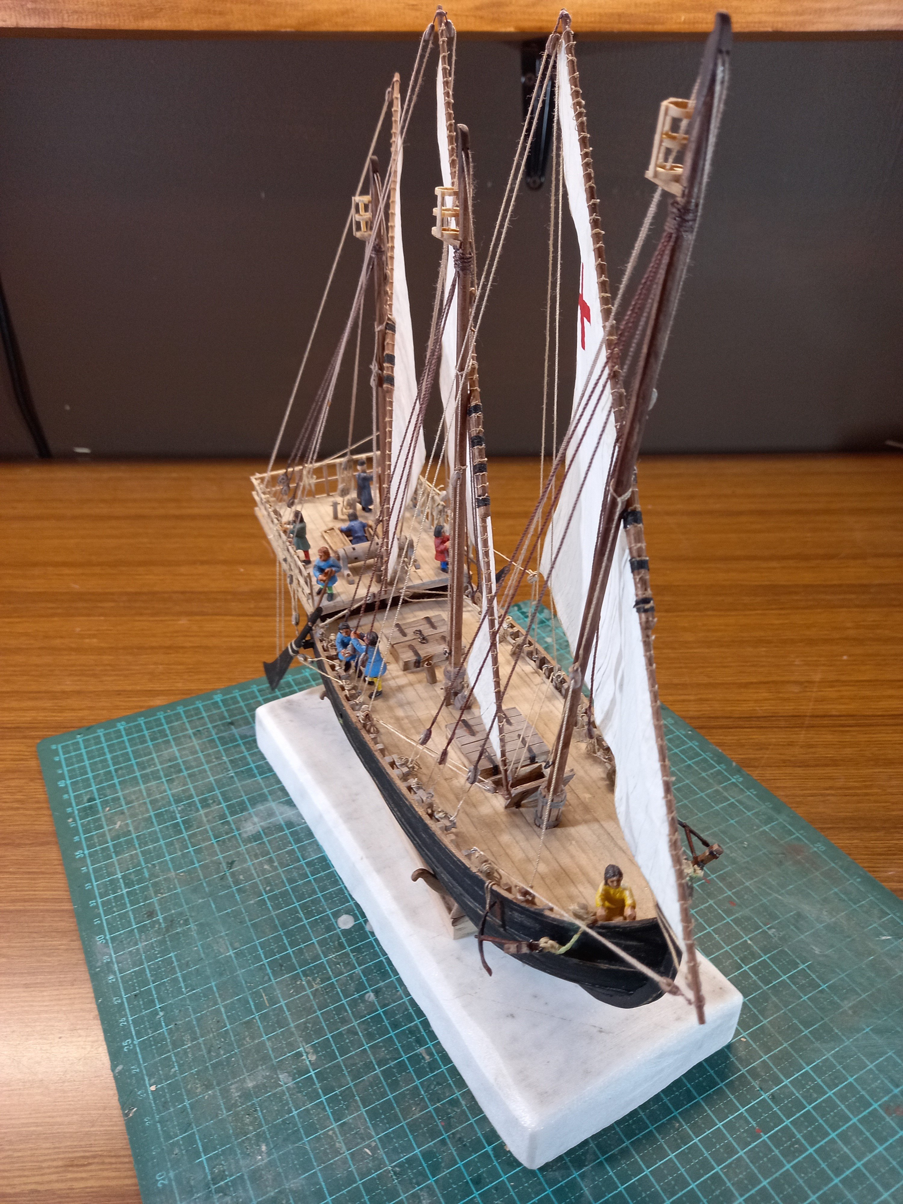
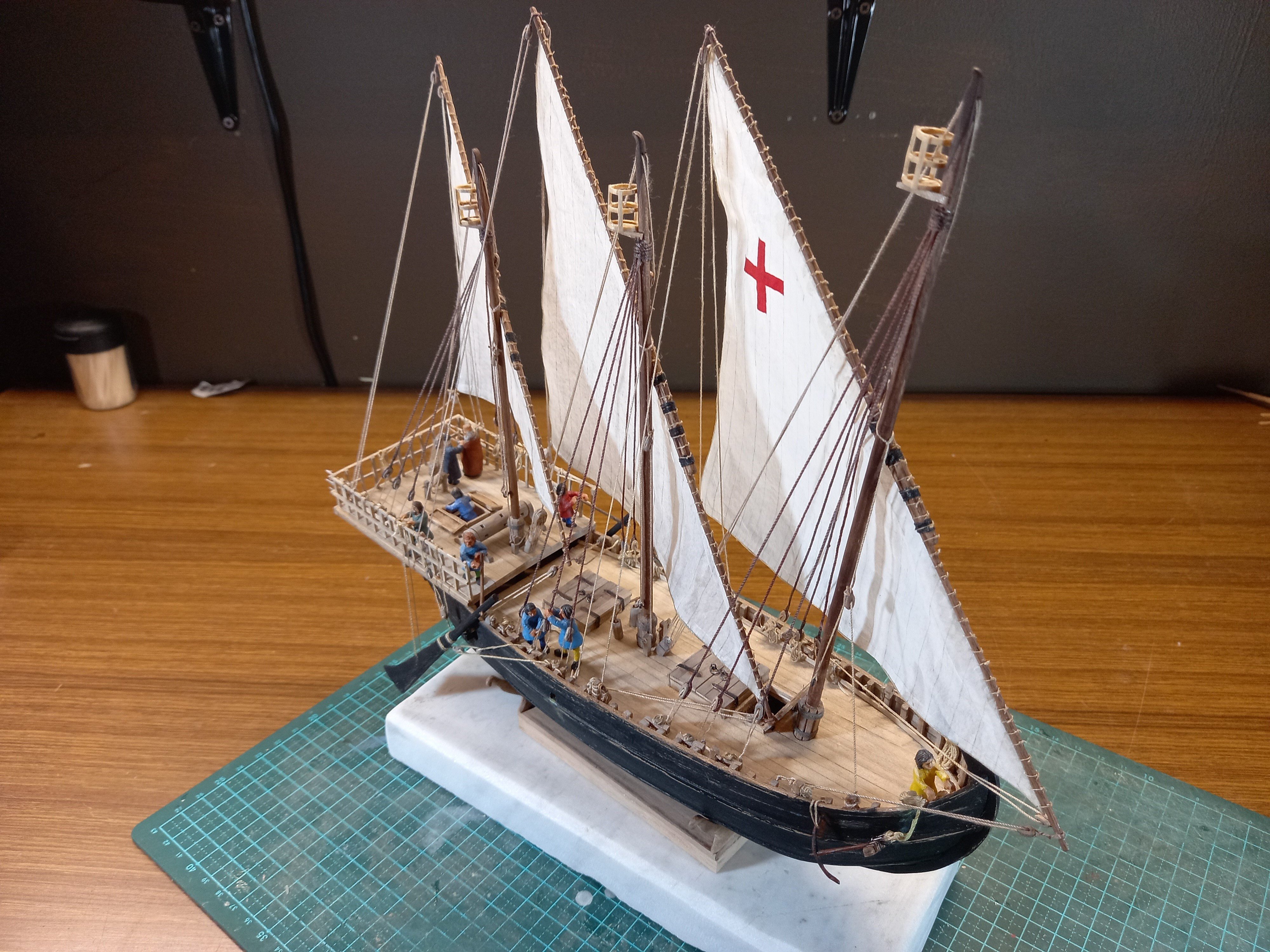
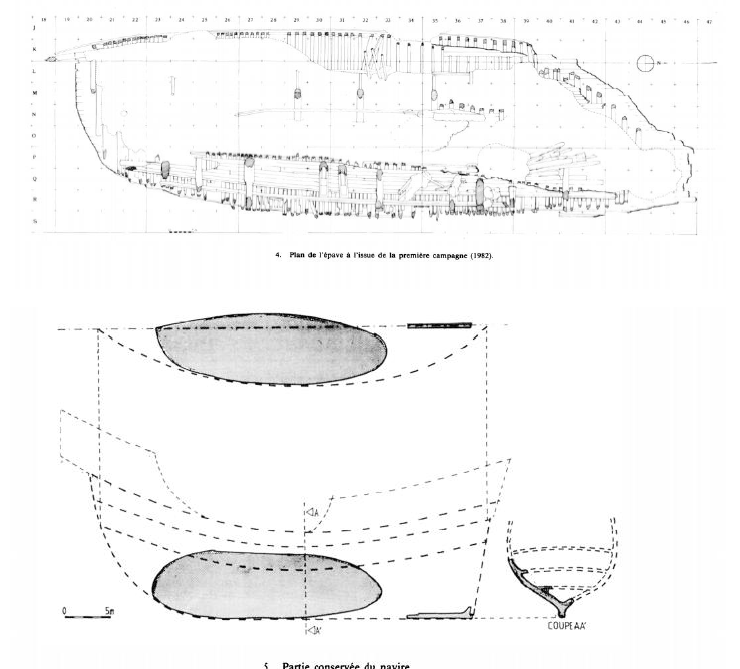
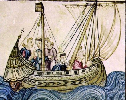
This is the barest beginning of this build log. Very much in the preliminary stage. The Lomellina was a carrack belonging to the Genoese Lomellini family. In 1516, she was hired to the French king who was carrying out a war in Italy. While in the harbour of Villefranche sur Mer on the French southern coast, she was hit by a tempest, capsized and sank. She may have been relatively empty of cargo, which could have contributed to the capsize. Though attempts were made to salvage her, they did not succeed beyond retrieving some of her cargo and armament. She was at least the second vessel of this name - the first was lost in the Greek islands in 1503. I'm assuming that a replacement was undertaken shortly after, so the current vessel was probably built in 1503-1504. Here is a picture (date unknown) of what I believe to be the first Lomellina, judging by the flags she flies (those of the Lomellini family) various details of the ship and the costume and armament shown in the picture. In the 1980s the wreck was investigated over a number of years, and very comprehensive archaeological reports produced. I am basing my reproduction on these reports and contemporary pictures of similar vessels. This is a diagram of the remains - like the Mary Rose, she ended up on her side, so much of her superstructure was preserved. Unfortunately, the forward part did not survive - such things as anchors etc in a working harbour over several centuries destroyed that part of the ship. My first job is to prepare drawings, which will take a while. Though they have a good idea of her overall length and breadth, and several cross-sections, there is still a lot to be worked out. Steven
-
Thanks everybody. I'm still working on the Ballarat paddlesteamer Golden City, but my next project will be a Genoese carrack, based on archaeological reports of a vessel named the Lomellina which sank in the southern French harbour of Villefranche-sur-Mer in 1516 and was investigated in the 1980's. It will be at a scale of 1:100. Steven
- 508 replies
-
- 10
-

-
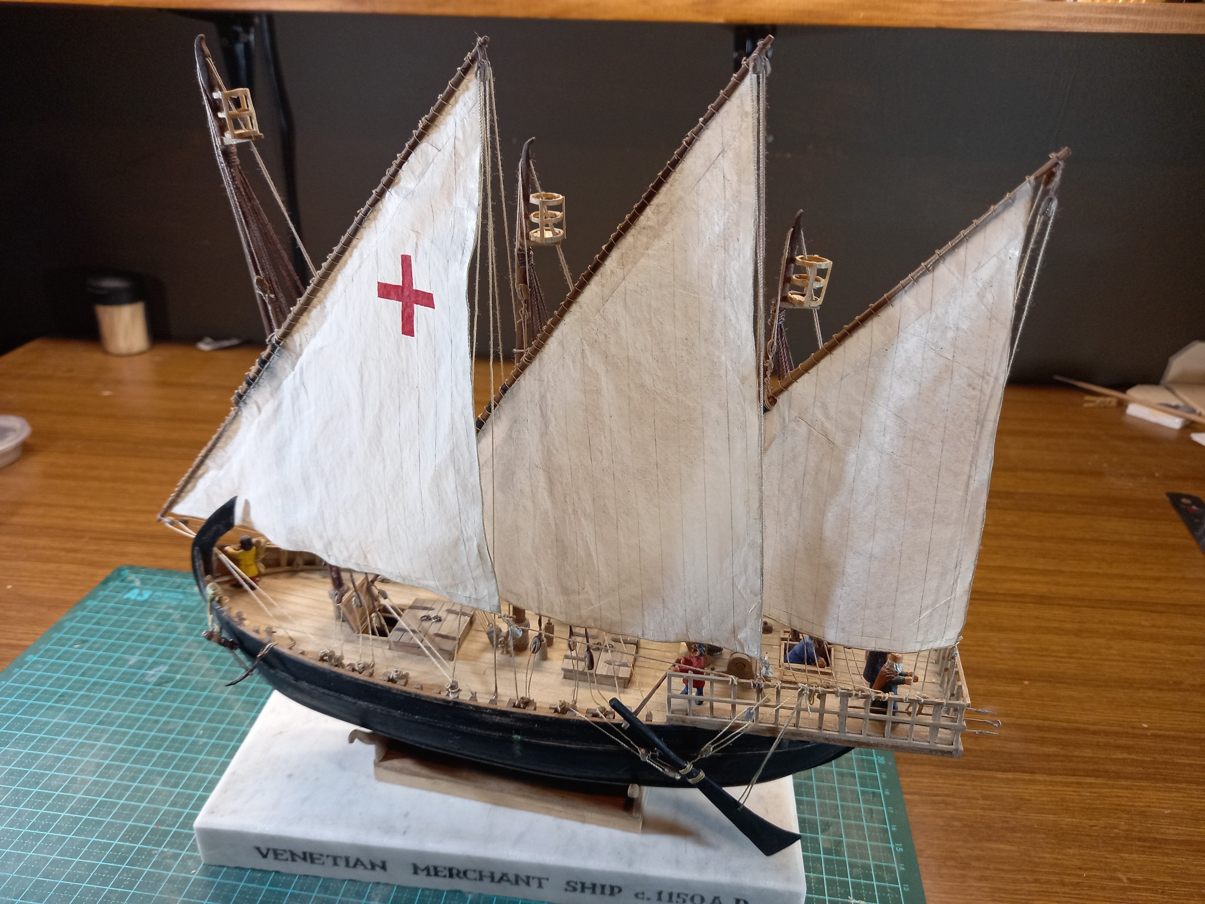
Such a beautiful shape. Progressing well. Steven
-
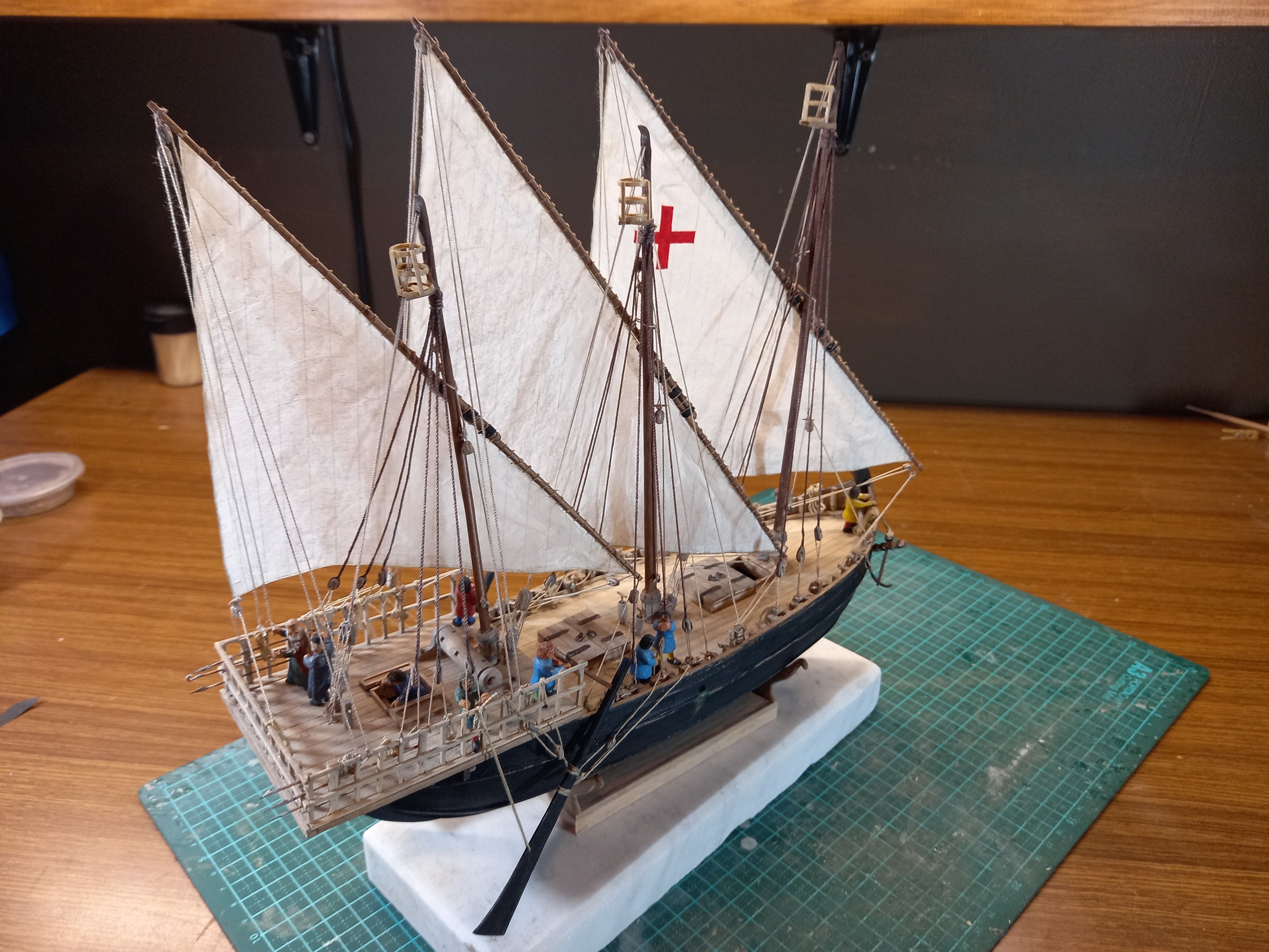
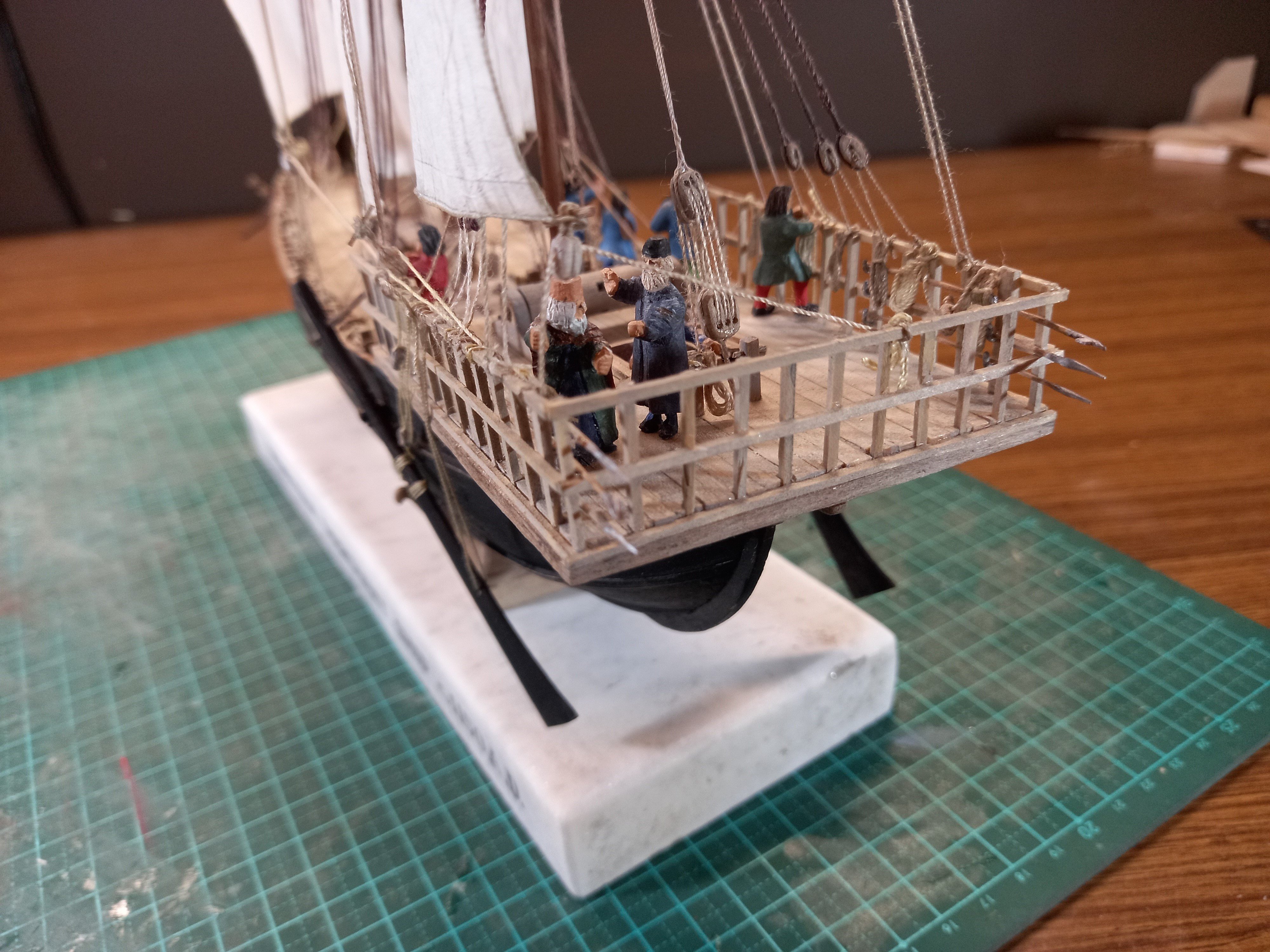
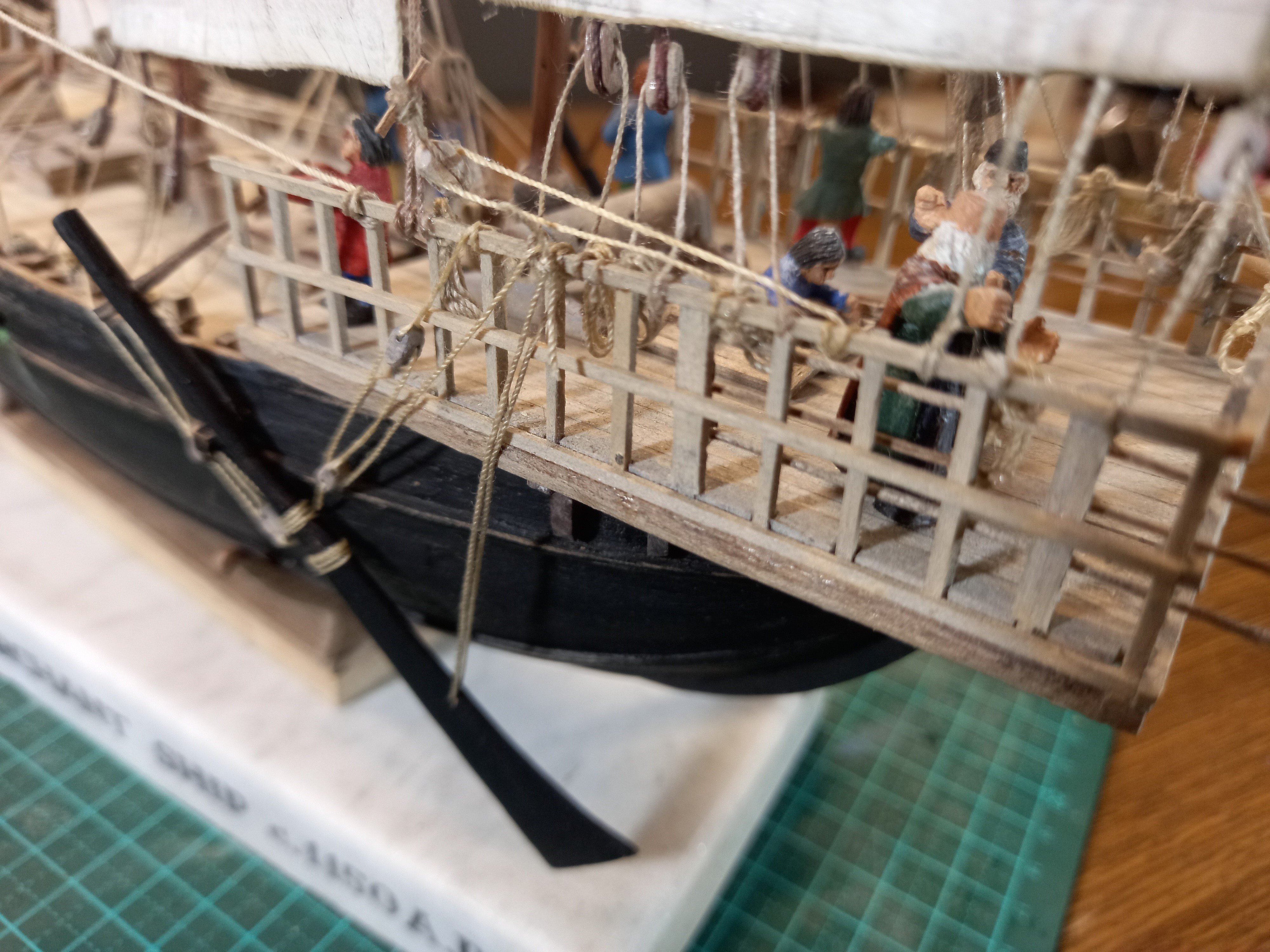
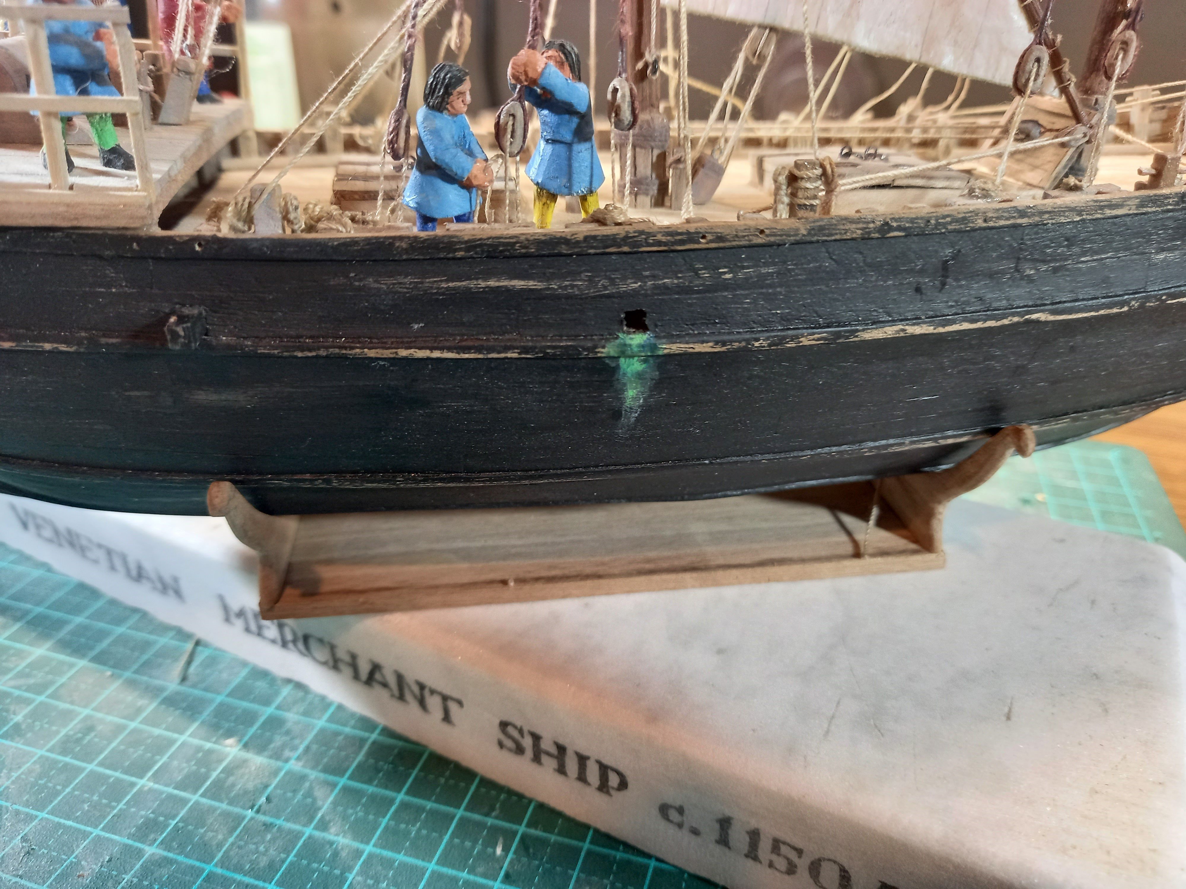
Starboard rudder tackle in progress . . . I made a peg out of bamboo to fix the rudder to its pivot (bamboo's a lot stronger than most woods). And glued the rudder in place with its tackle attached And complete (whew!) But before I add the larboard rudder I need to sort out the loosened-off lee shrouds and work on the 'belly' of the sails. Watch this space. BTW, notice the marine growth at the pump outlet is less 'neon'. I followed Druxey's advice - sort of - by giving the stain a light wash of reddish-brown (close enough to the complementary colour to bilious green). Steven


- 508 replies
-
- 12
-
-

-
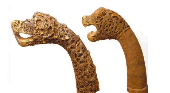
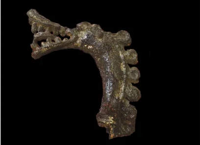
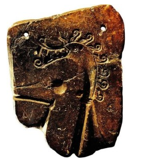
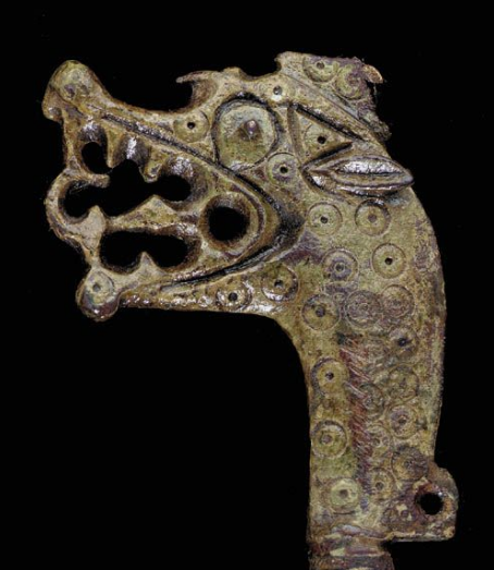
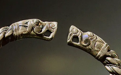
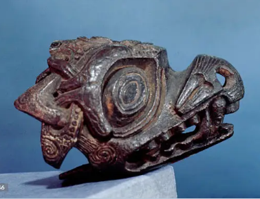
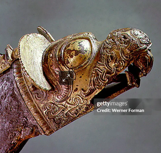
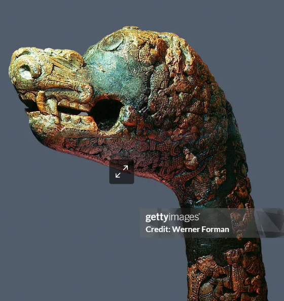
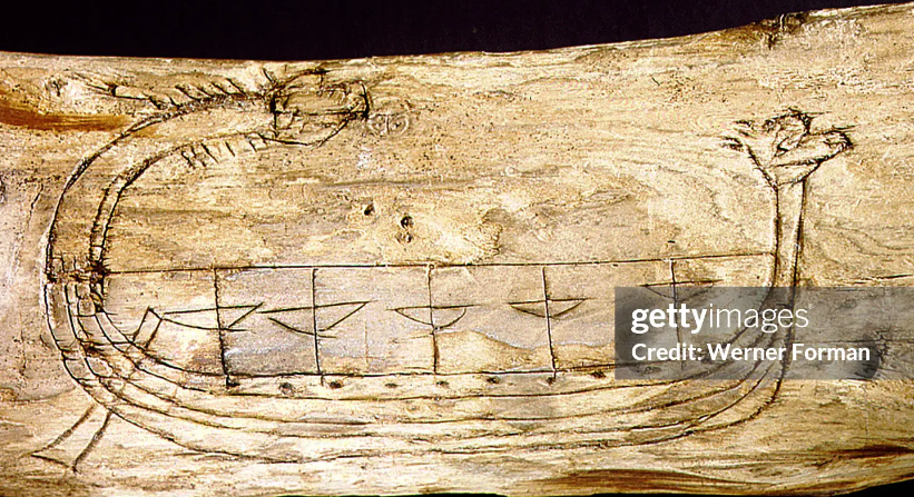
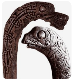
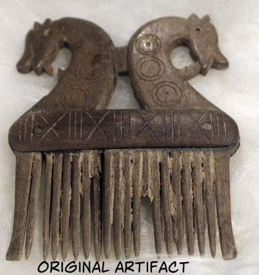
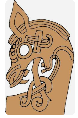
I'd recommend you keep it simple. No need to try to emulate the top two - the unknown Viking who carved the one on the left is known to academics as the Academician because he was so expert. I must say I like the middle one in the second row (I've only just discovered him - he was on a Sotheby's auction site). Relatively simple carving job, and the decoration is all just what they call ring and dot (you can see why). I think that'd look pretty cool. I think the escutcheon pins should be fine for the bosses, and many of the shield decorative patterns are very similar to those shown in contemporary images. Looking good.
-
Nice work, mate. Those oars look good, and so do the benches for the oarsmen. From my reading, the most commonly held opinion is that the oarsmen sat on their chests of possessions, but I stress that's opinion - to this day nobody knows for sure - nothing's been found either way. usually known as a boss. Those shields look very good - that was a lot of work building them from planks. I'm not sure if you're familiar with this, but it's the most comprehensive article I know regarding the decorative designs on Viking shields (and other things about them as well, including how the handle worked). https://www.scribd.com/document/497550805/Viking-Shields - sorry about all the ads and stuff. Regarding dragon heads, there are quite a few images online but just check whether they're the real thing or modern 'interpretations'. Here's some of the genuine ones: That should give you plenty of choice Steven
- 48 replies
-
- 10
-
-

-
Well, what info I have I got from Woodrat's 14th century Round Ship build, that rudders could be rotated up out of the way when not in use, (e.g. when only one was being used) and also were to be removed and held by the harbour authorities while in port (so they didn't do a moonlight flit without paying their harbour dues). Steven
-
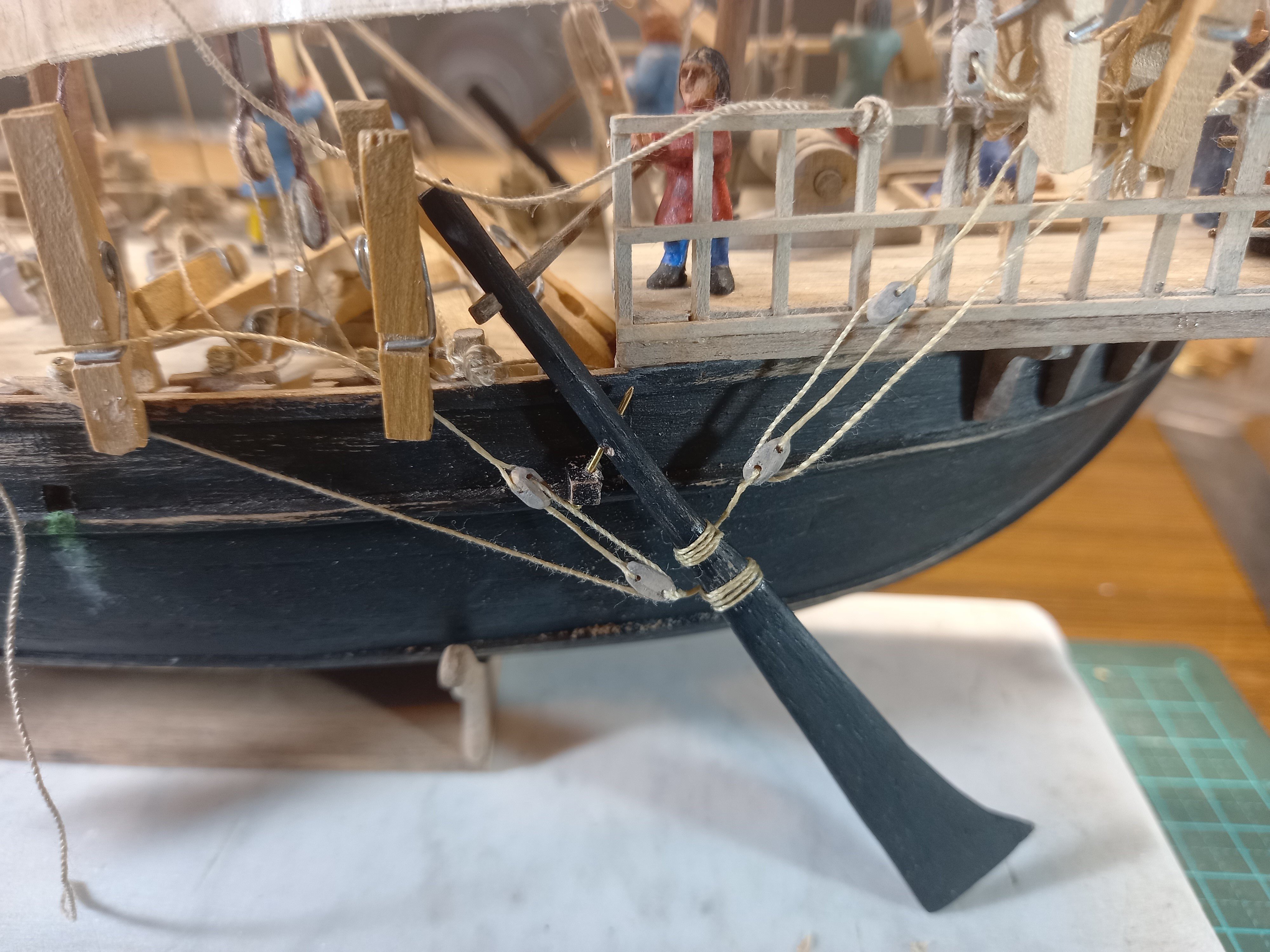
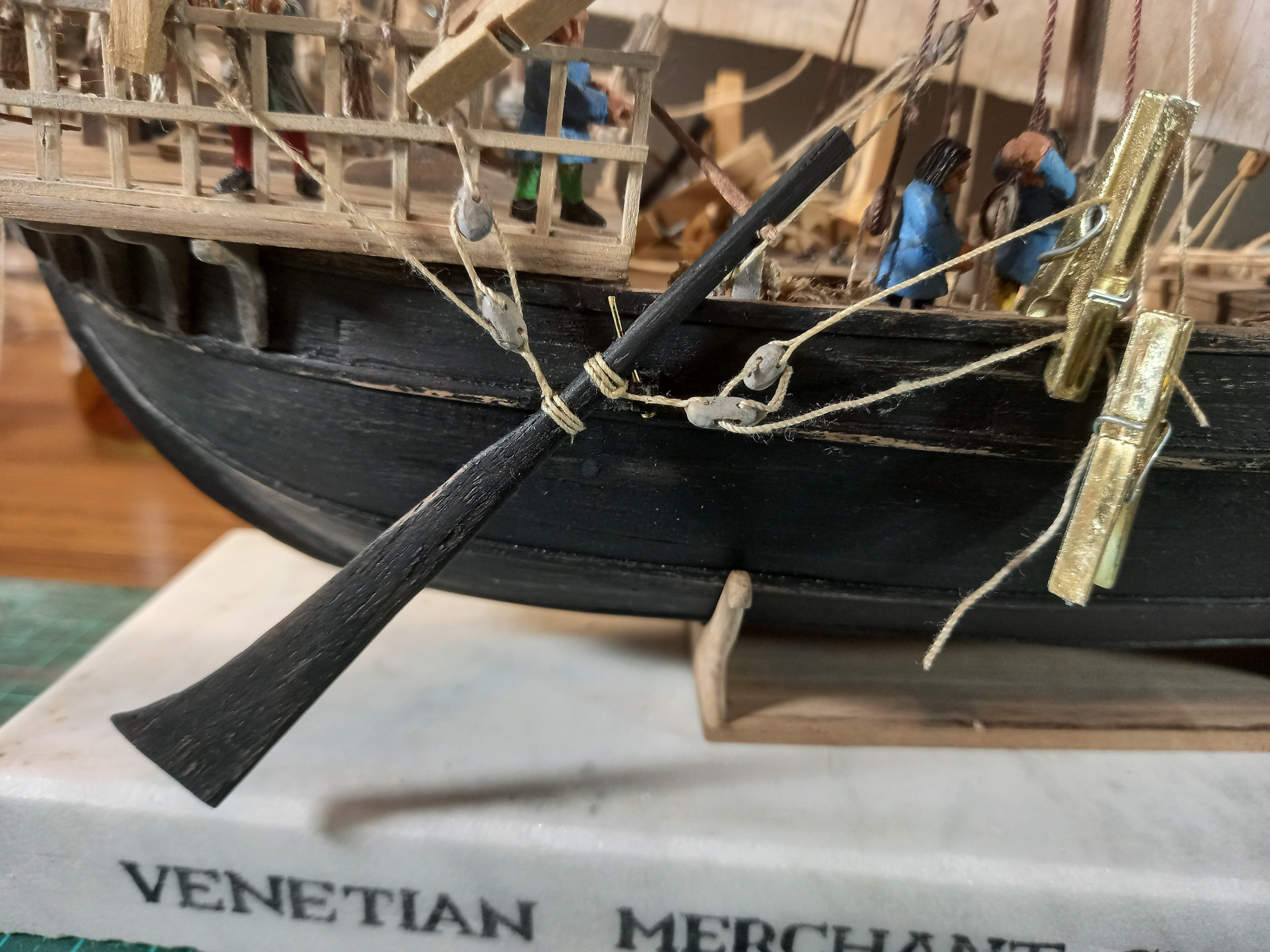
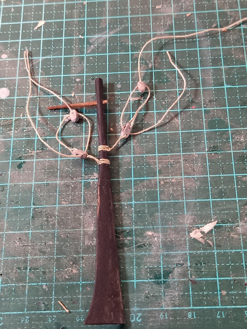
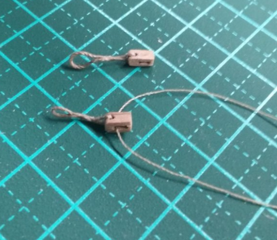
Here is the comparison between the rudder tackle in its first iteration and how it is now. The first (starboard) rudder still has its old (too massive) blocks and ropes, and the tackle is attached too close to the pivot. And here is the larboard rudder with its new, lighter blocks and ropes, and location further from the pivot. Still dry fitted, and I have to work out exactly where everything gets belayed, but I'm a lot happier with this. Now to fix the other one. Steven


- 508 replies
-
- 13
-
-
-
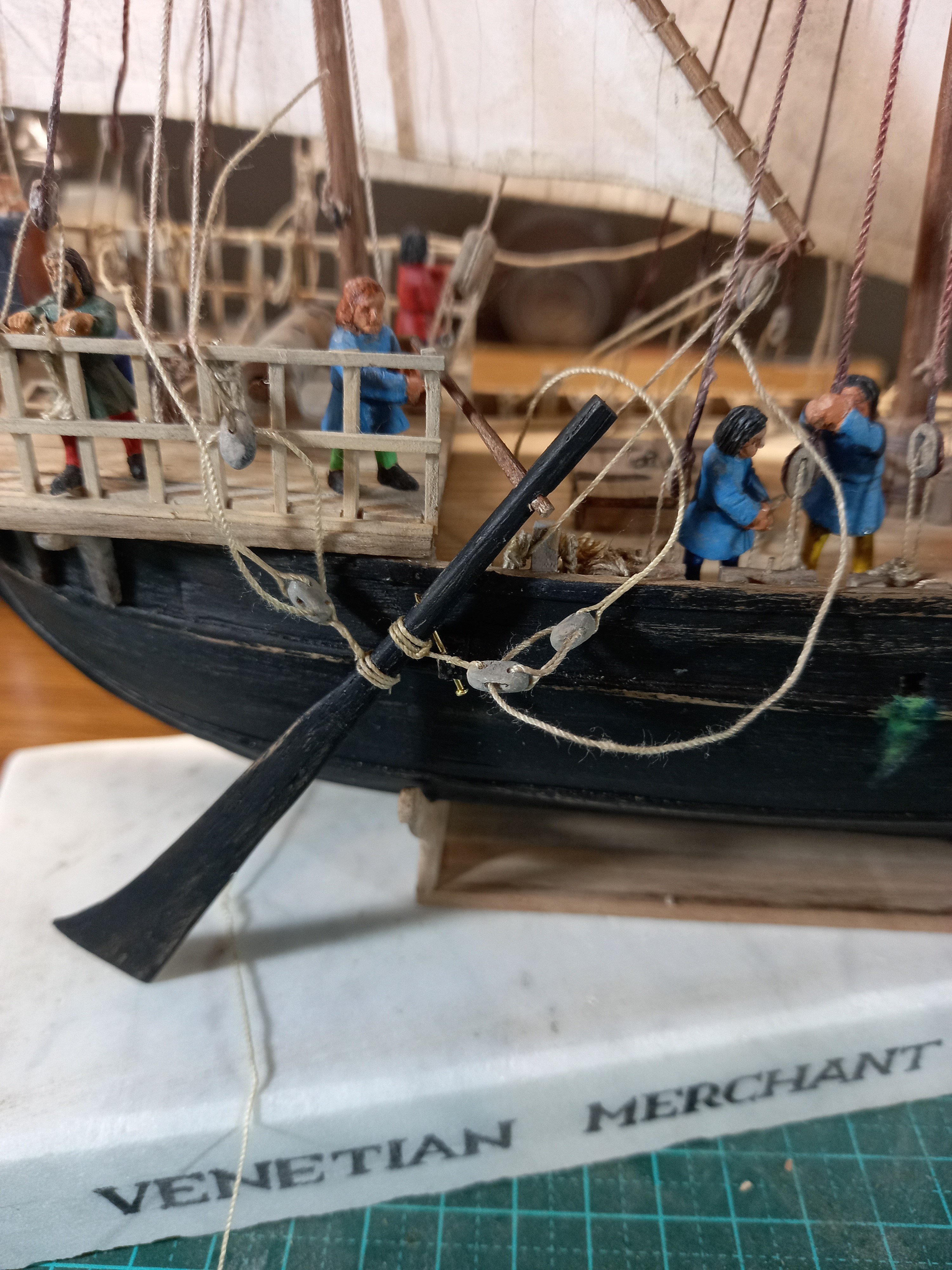
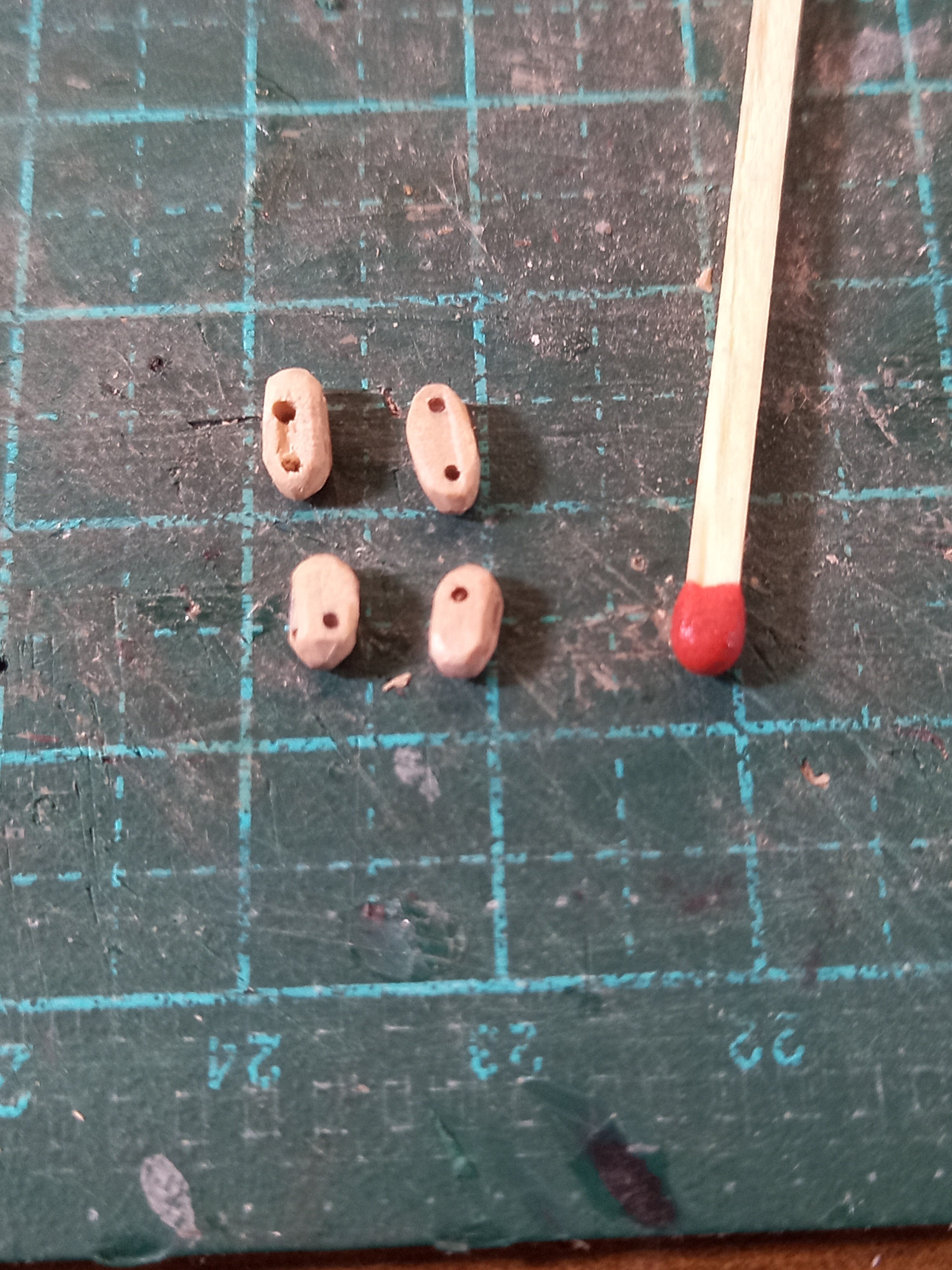
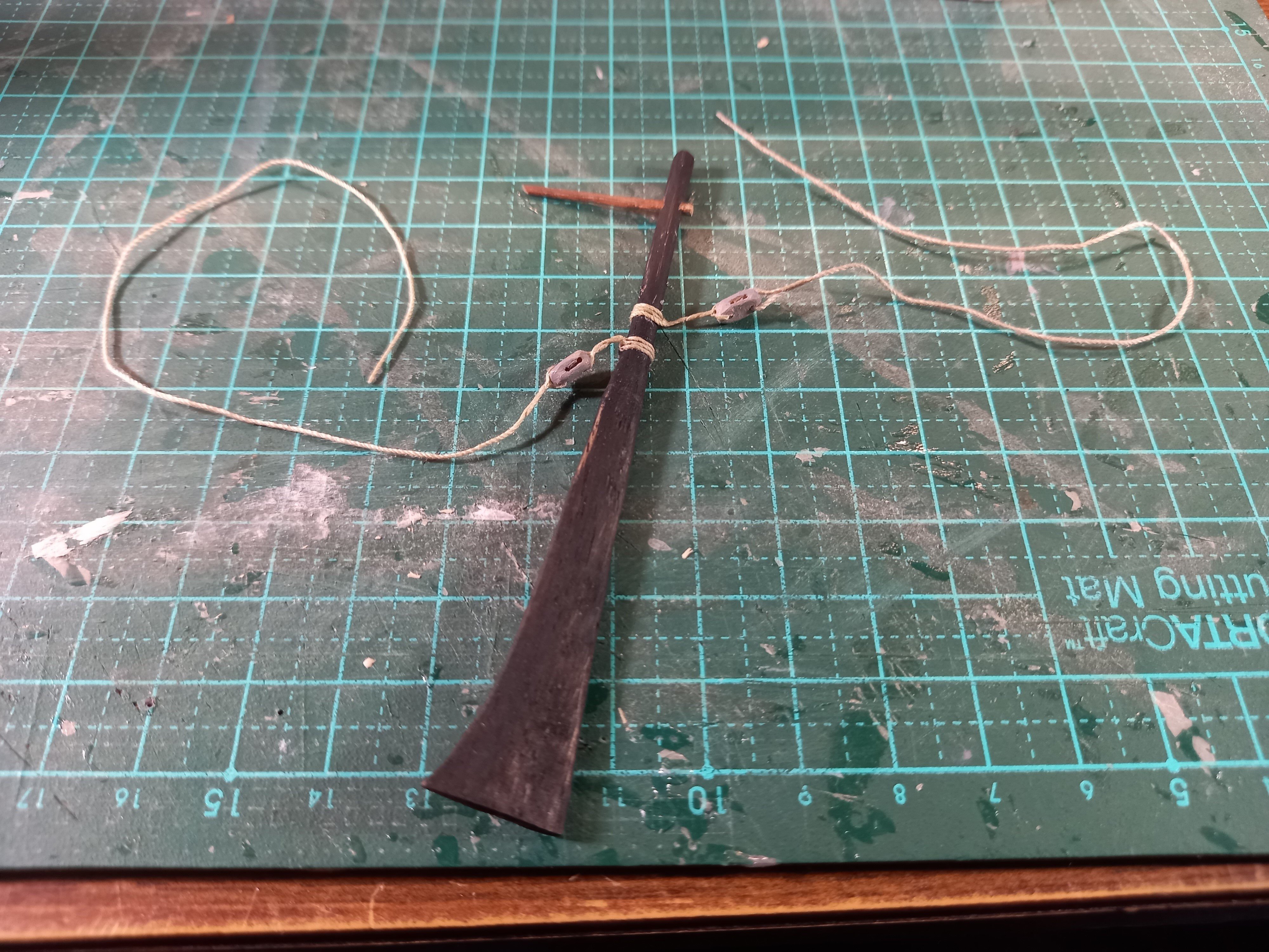
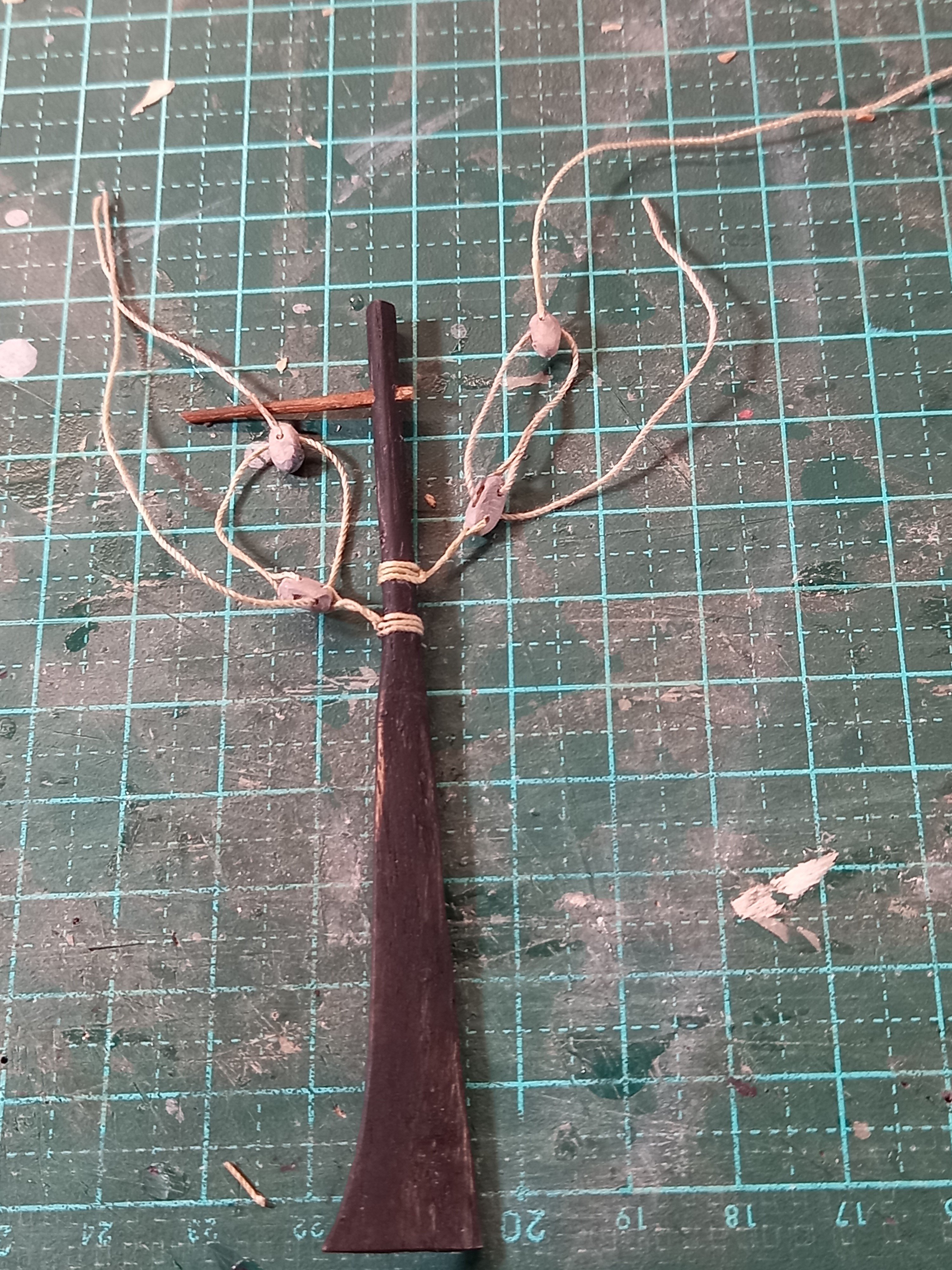
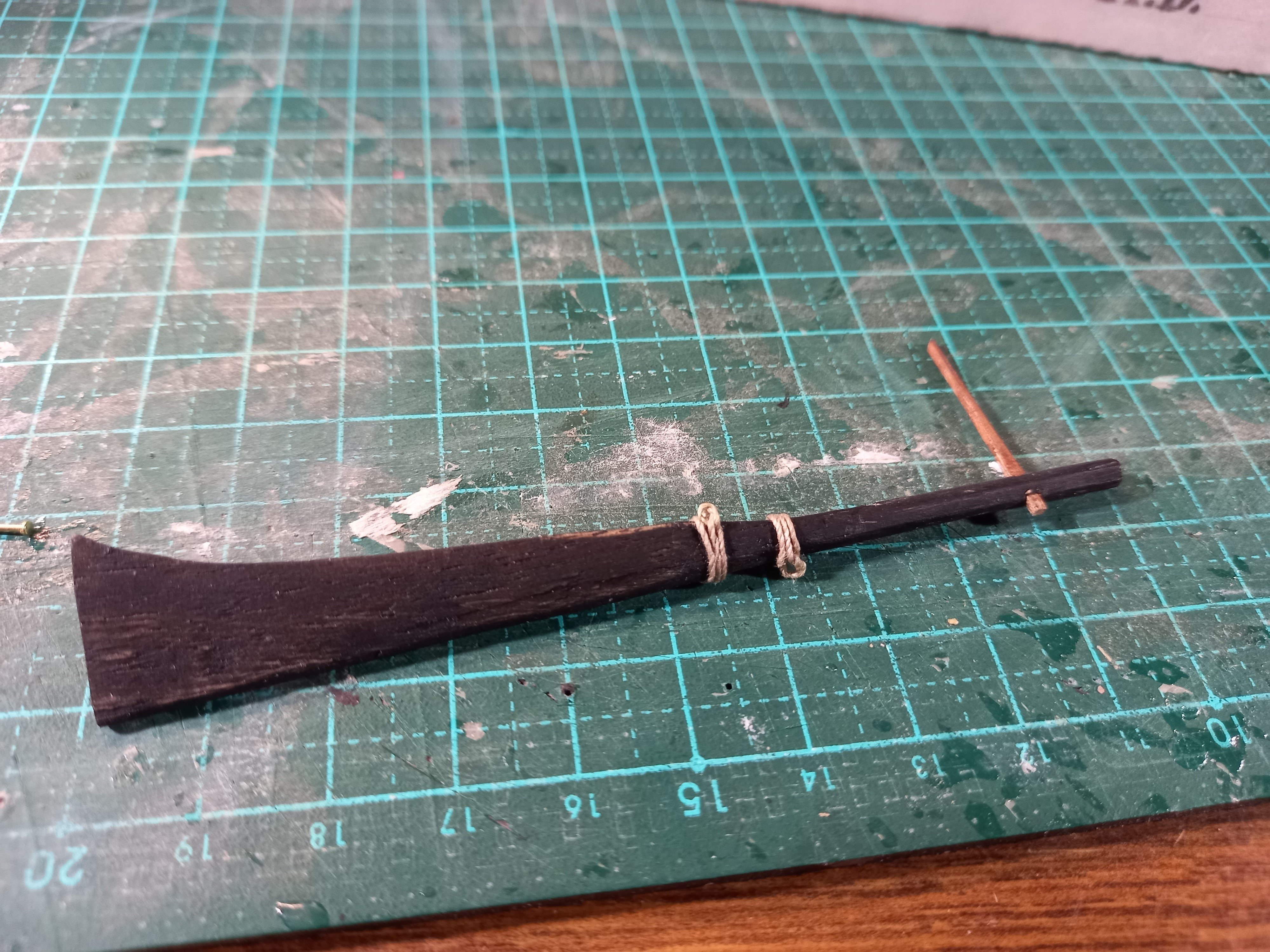
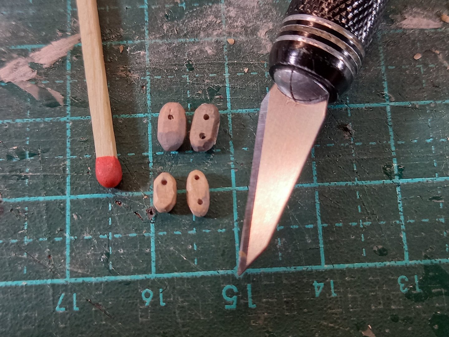
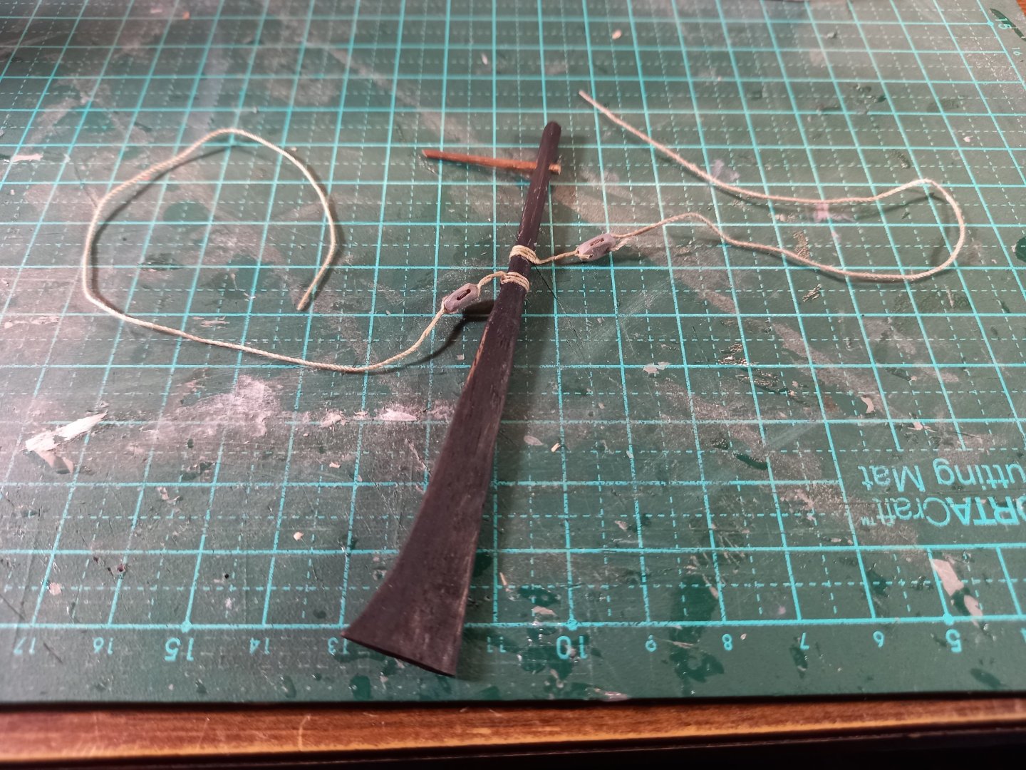
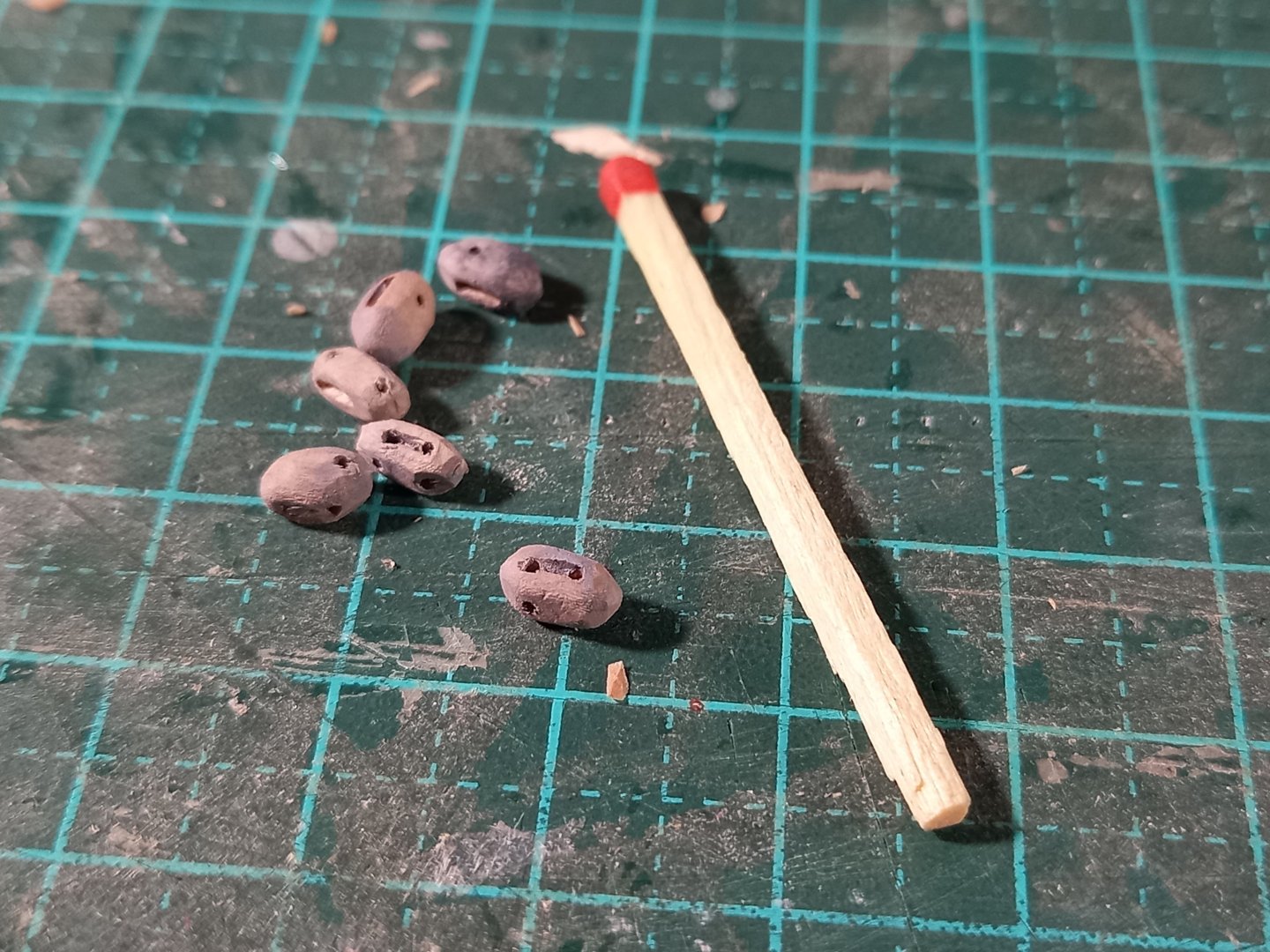
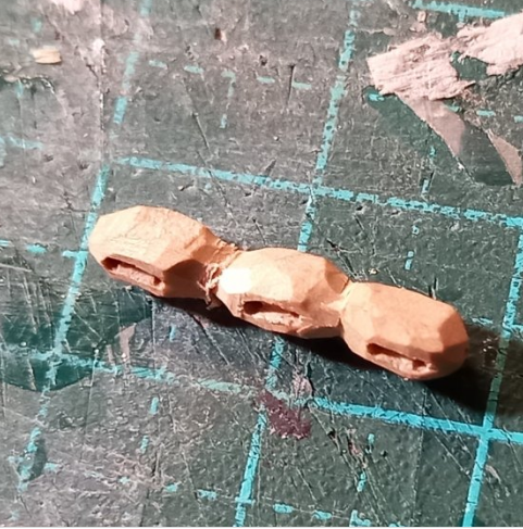
Thanks for the likes, everyone. Cathead, those colours aren't quite so 'neon' in real life - it's partly the camera's fault. But I do still want to tone them down a bit. My little collection of tubes of acrylic don't seem to have the range, so I'll try mixing blue and yellow enamel and see what that produces. Now, as to the rudder tackles. Here's a photo of one rudder dry fitted with the tackles in place. The concept is good, but the execution is sadly lacking. First, the tackles are mounted too high on the rudder, particularly the forward one - not enough room for the tackle to fit between the mounting and the proposed belaying point at the gunwale. And not enough leverage to swing the rudder one way or another - the fixing points need to be further away from the pivot point. Secondly, the whole thing is too massive - blocks, ropes, everything. So I've started shaving the blocks down, and will be using a thinner thread for the tackle. Unfortunately this means pulling apart and changing everything I've done over the past week or two, but it's worth it to fix this problem. Here are two of the blocks unchanged (top) and another two I've shaved down (bottom). Plus the craft knife (No. 11 blade) used for the job, and the enormous matchstick I use for size comparison. After shaving them down with the craft knife I used a fine file to smooth them off. And here are the four blocks for the larboard side shaved down to size. I'll mount these again (with fine thread) and see how they turn out. Then I'll do the same for the starboard rudder. Steven


- 508 replies
-
- 12
-
-
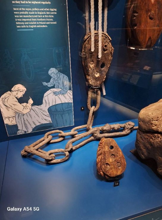
Just a quick question - when you get to the rigging, are you planning to duplicate those amazing multiple-hole deadeyes? Steven
-
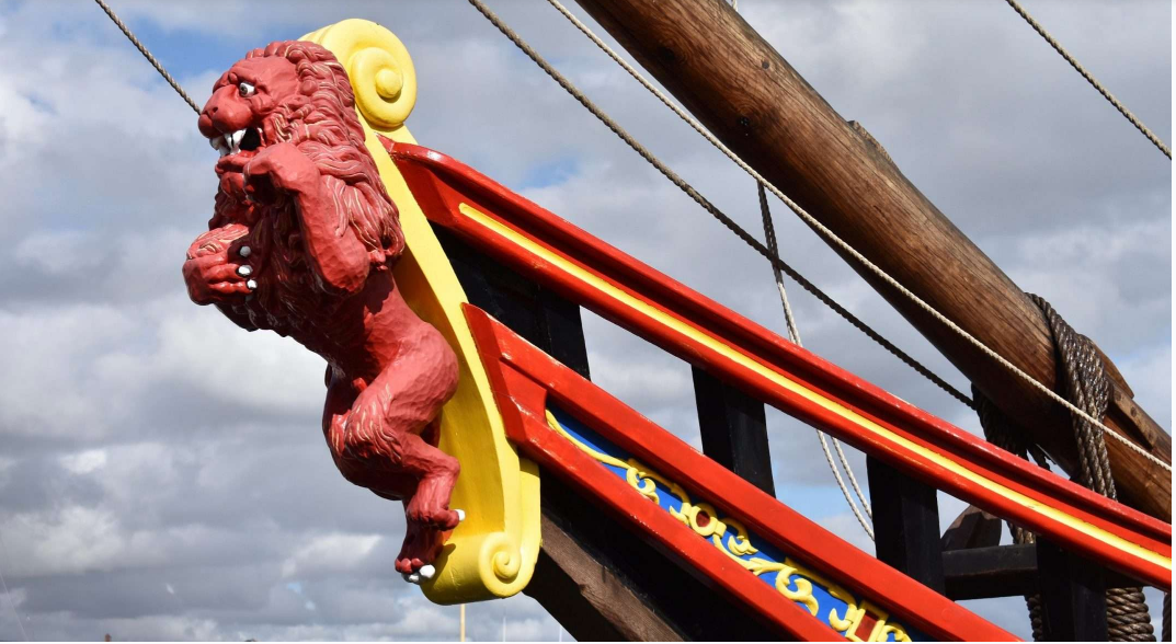
I see what you mean about the lion. It's plastic, is it? I'd say with a bit of work with a scalpel with a Number 11 blade, you might be able to improve the detailing and turn it into something worthwhile. Maybe a bit difficult to get it as good as the one on the full-sized ship (below), which is, frankly, superb - but certainly better than what they supplied you with. I've done a lot of woodcarving, but I wouldn't be able to get a result that good. Steven
-
The model may be big, but the full-sized replica/reconstruction is tiny! I went aboard her when she was being built, and they were giving away small off-cuts of oak from building her. I still have it. She's a beautiful vessel, but it's hard to believe something that small actually sailed to the other side of the world. Your model is going very well. I look forward to seeing more progress. Any chance of a photo of the 'lion' figurehead? Steven
-
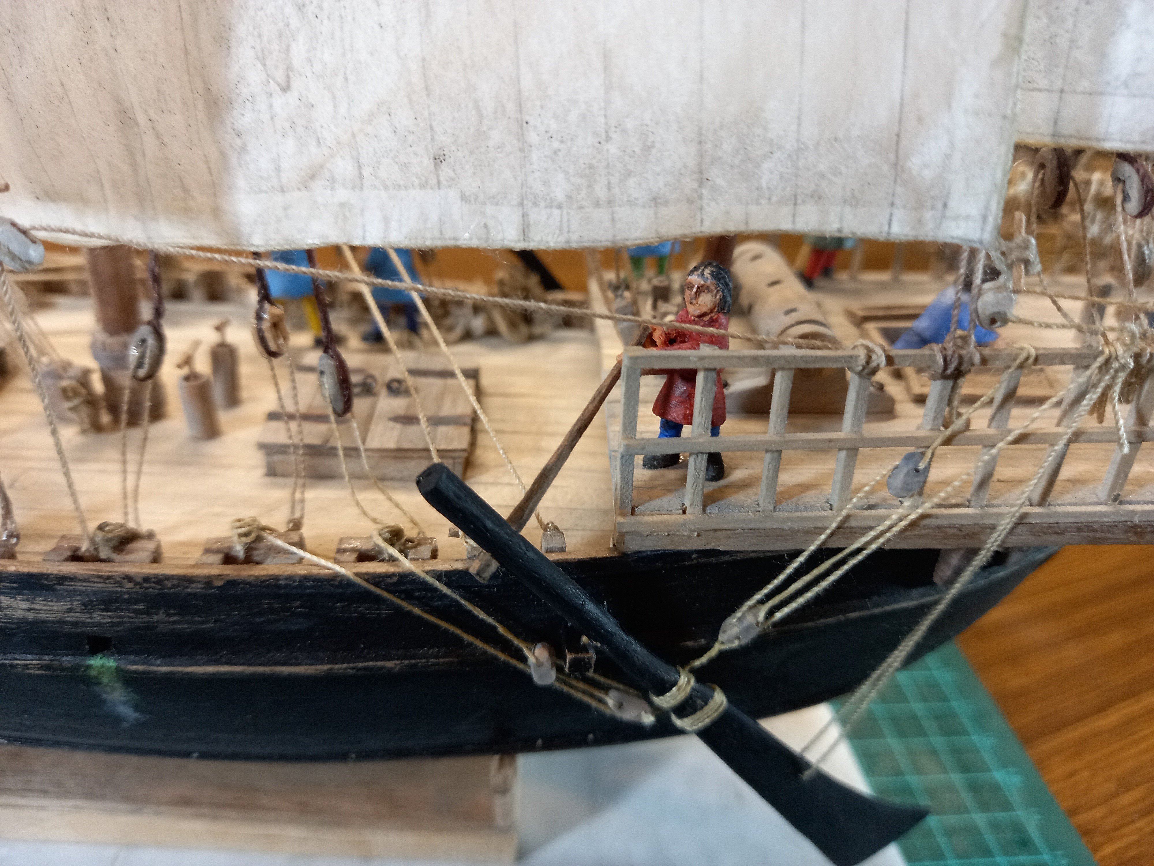
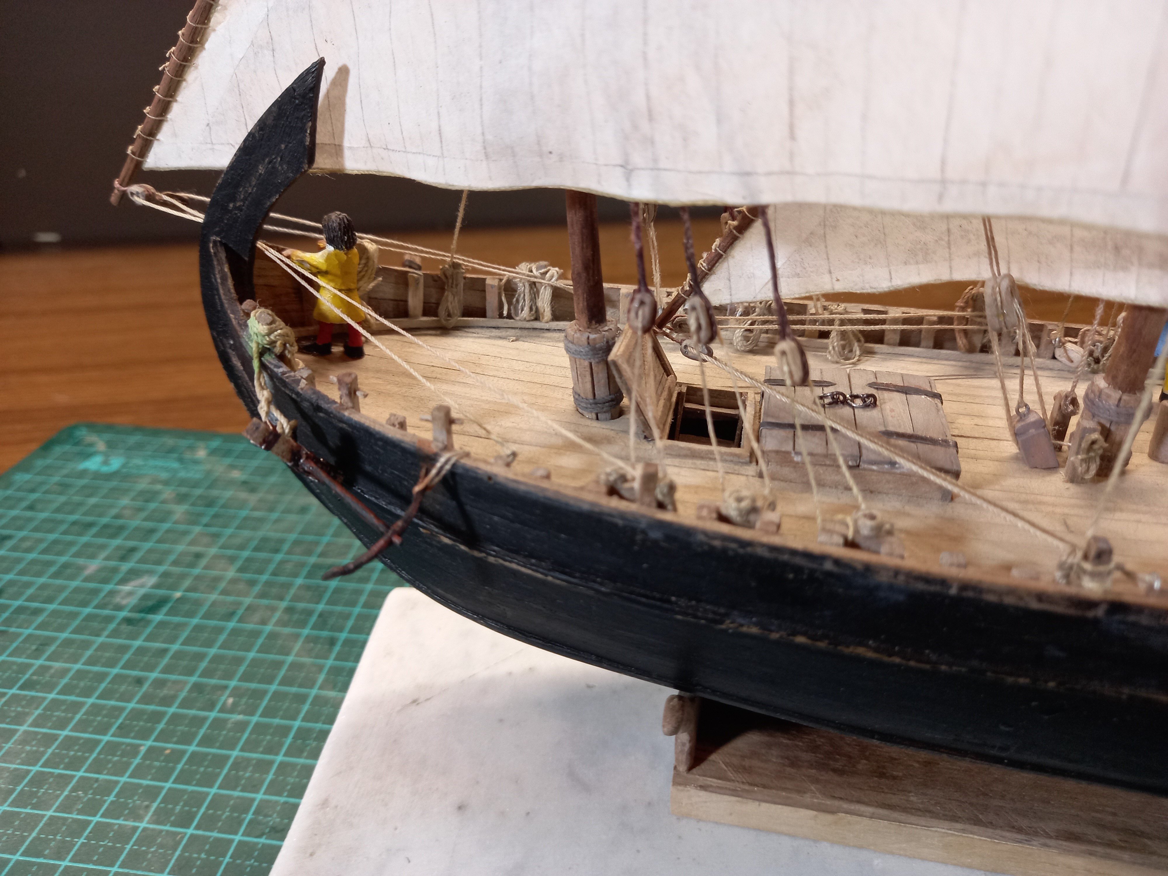
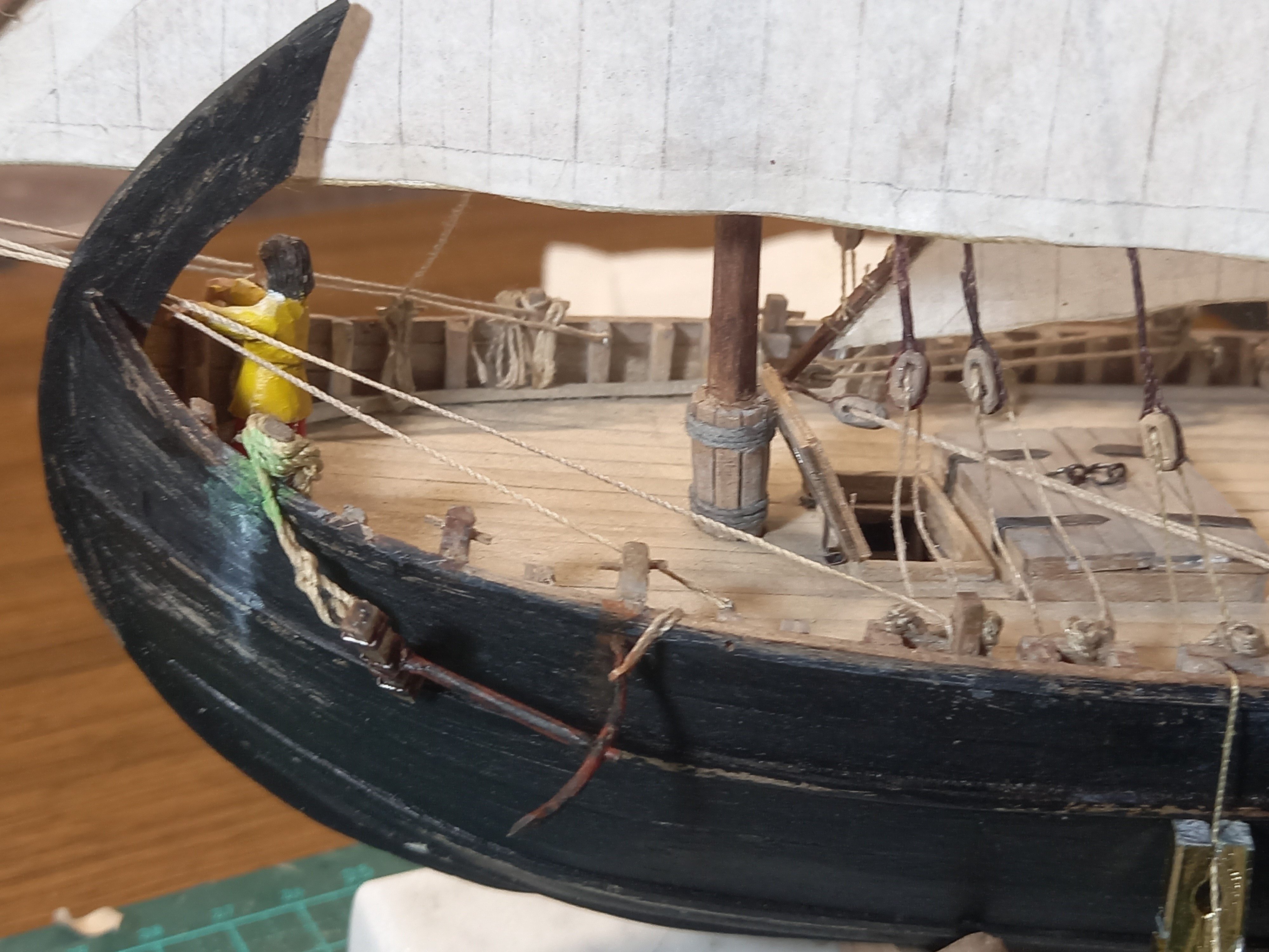
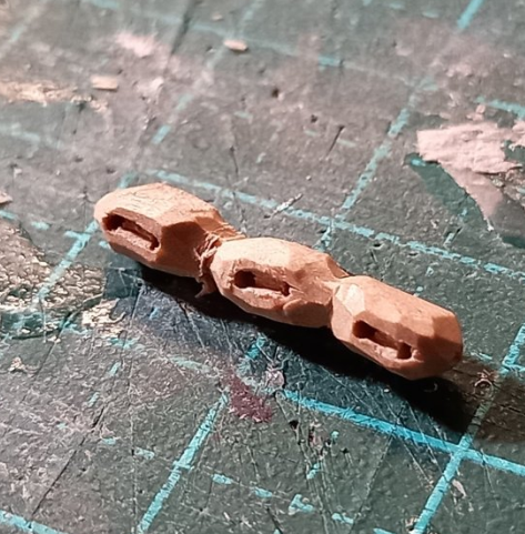
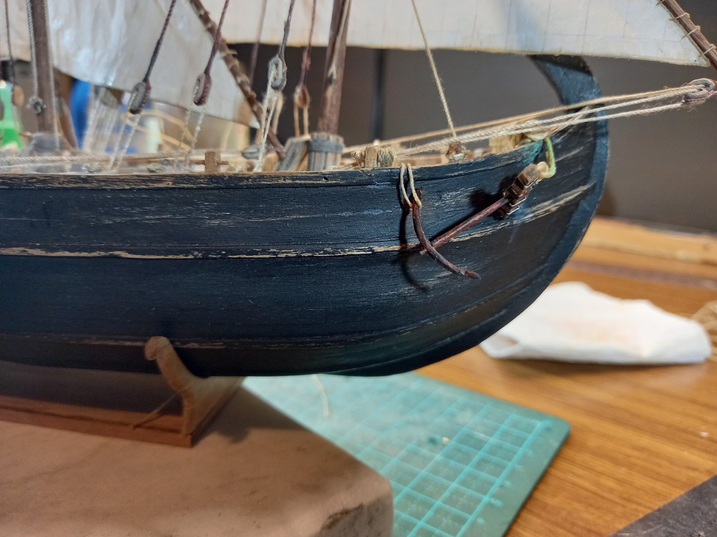
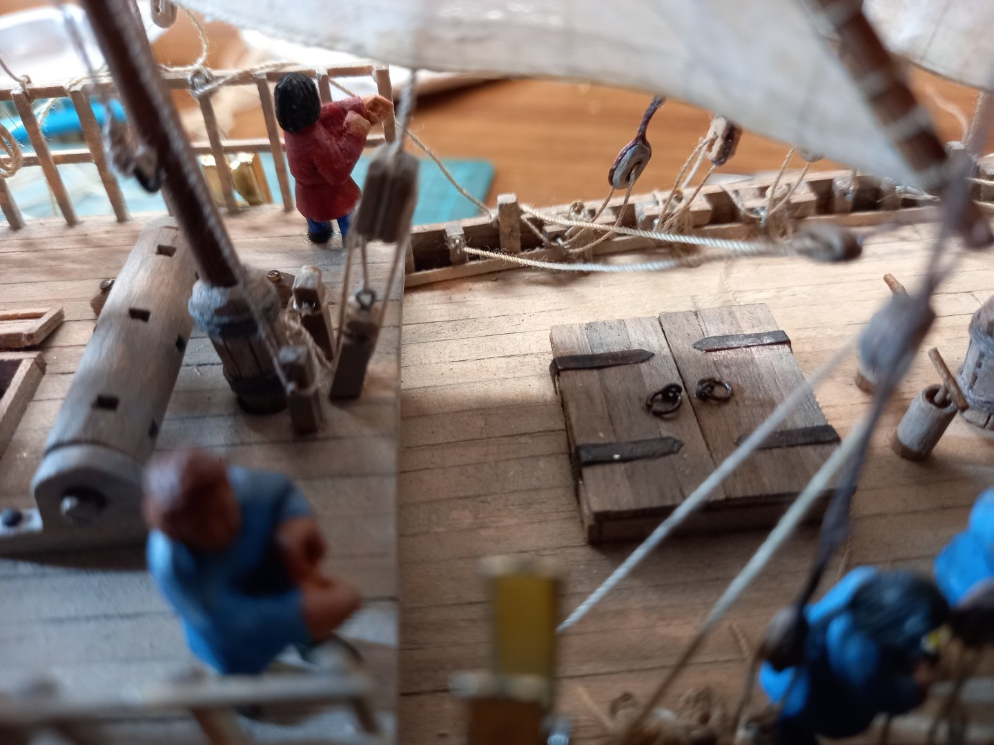
The larboard anchor fixed in place and the weathering done. I'd also had to remove the guy in yellow while I worked on the anchor cable coils and the tacks for the foresail. Now he's back, staring off forrard - no idea what he's looking at. And more work on the rudder tackle: Making the new-style Stropless blocks (carved from fruit-wood - pear or perhaps apricot) Installing the lower blocks: And adding the upper blocks and the rest of the tackle for the starboard rudder - see close-up photo of original carving in post #469 above. The larboard rudder is under way. Steven

- 508 replies
-
- 12
-
-
Yes indeed. Many vessels have come to grief in those waters. Steven
-
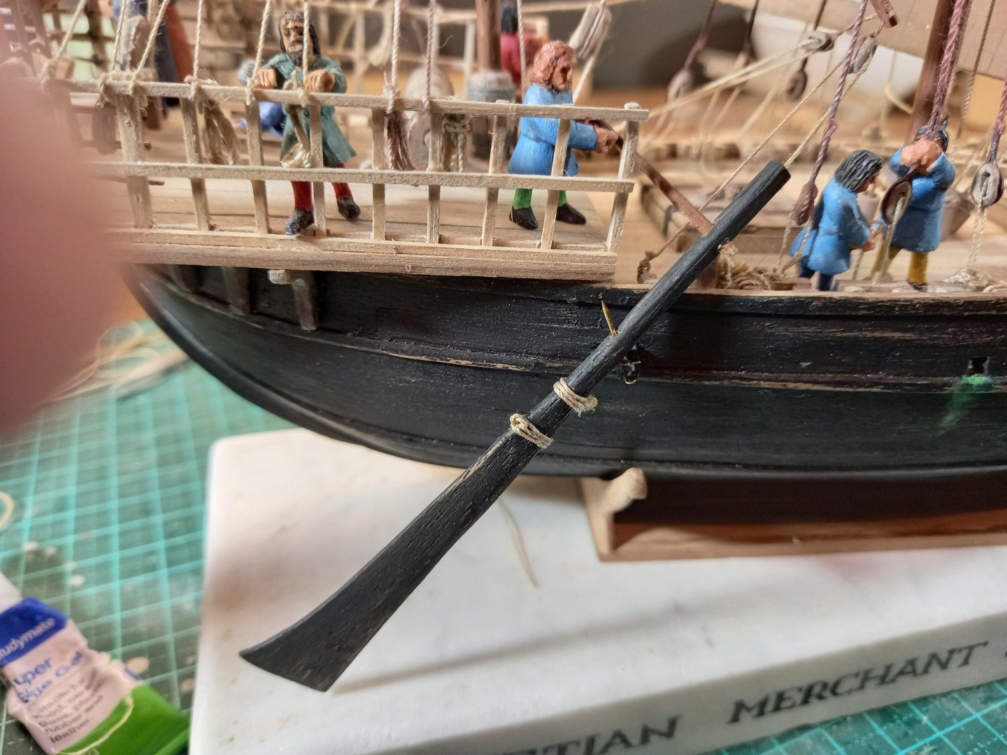
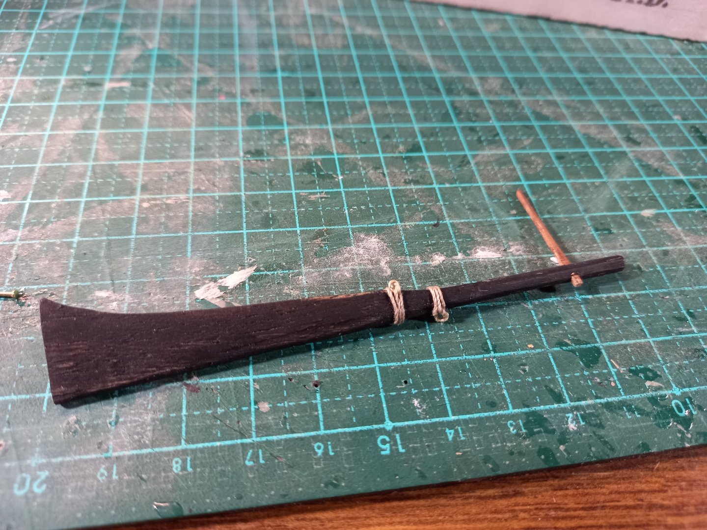
By the way, as far as most Aussies of my generation are concerned, this is a Strop. Steven

-
First, thanks everybody for the likes. JacquesCousteau I'll have a look at that idea. So far my colour-mixing hasn't come up with the colour I need. I still need to do some more experimenting. Thukidides, I agree totally. I find half the fun is in the research. Steven
-
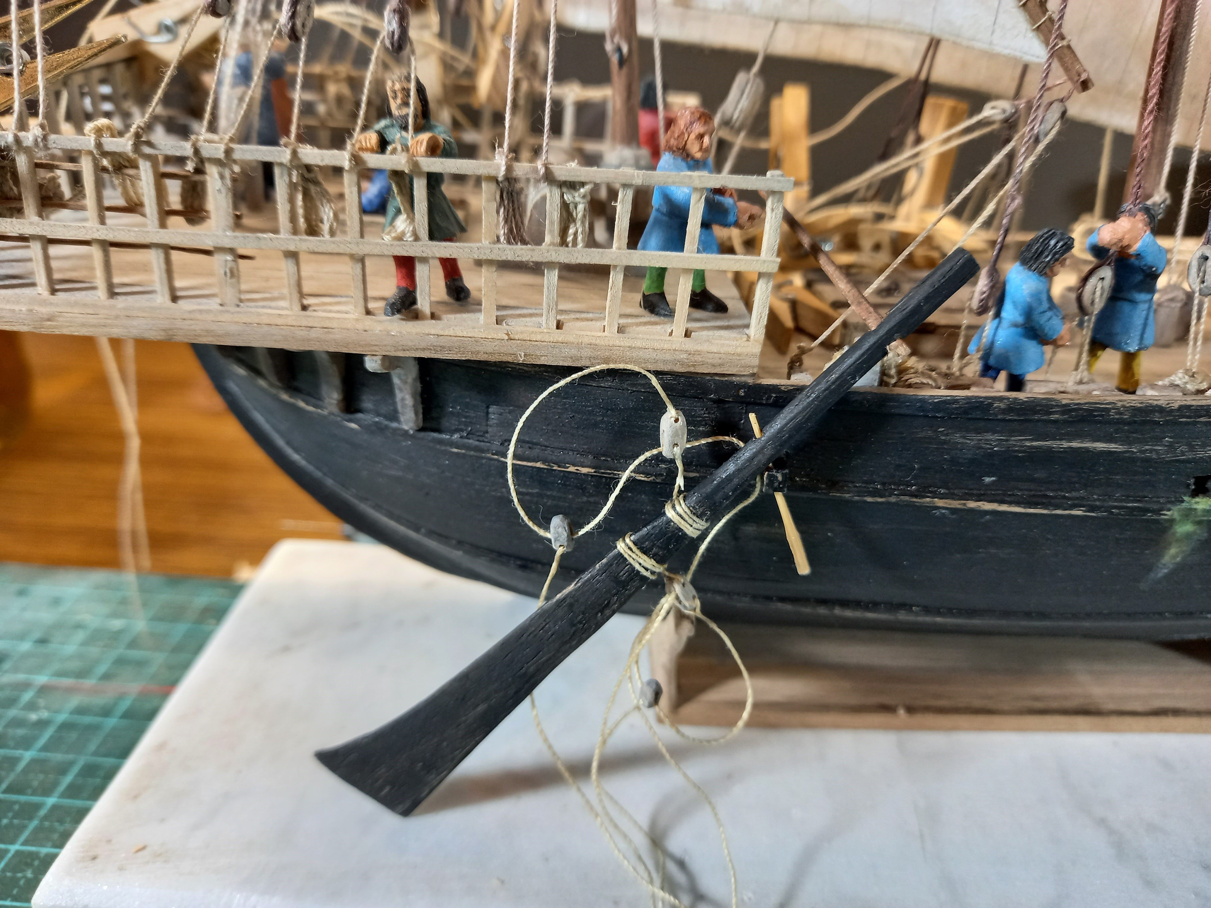
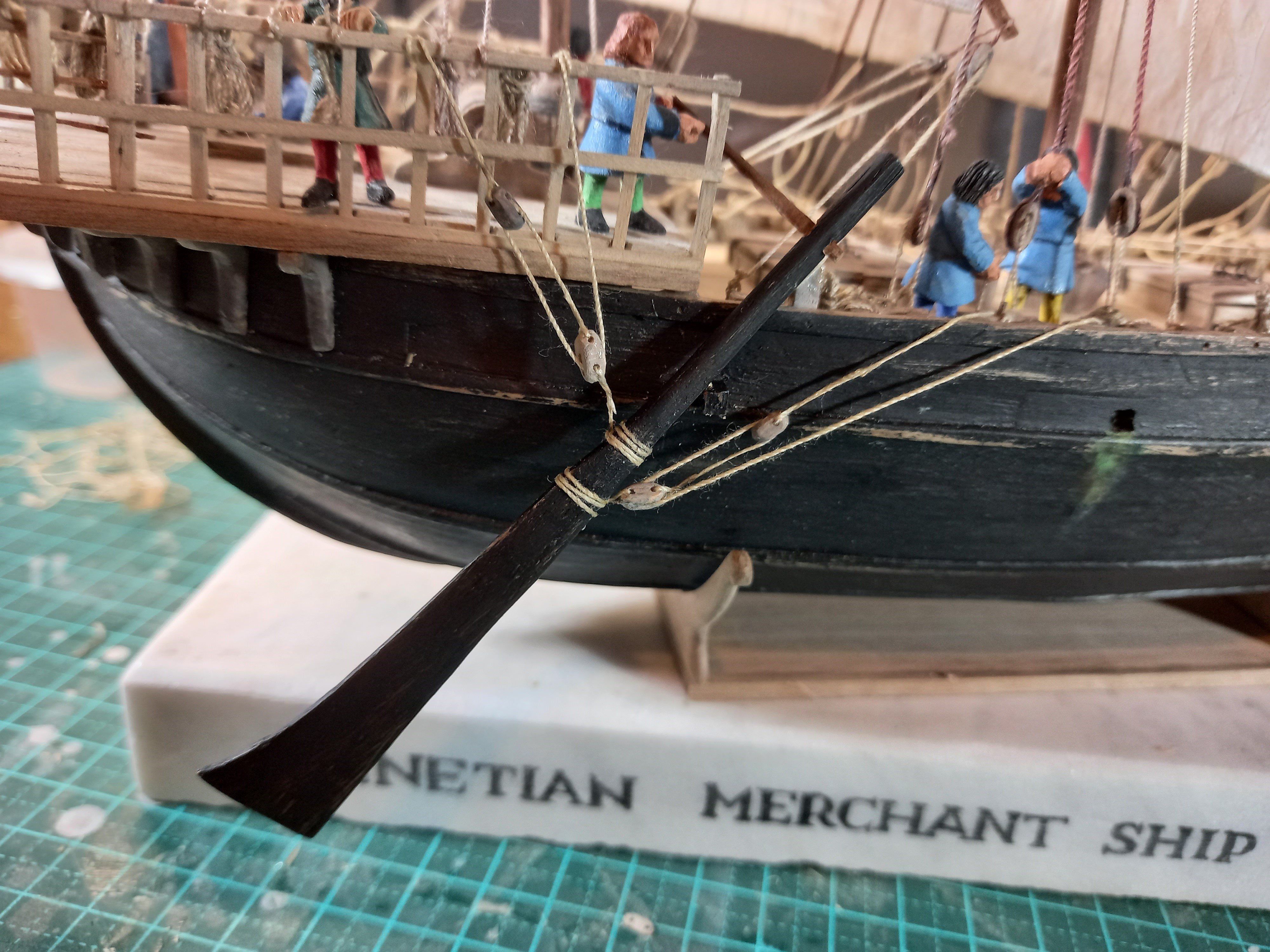
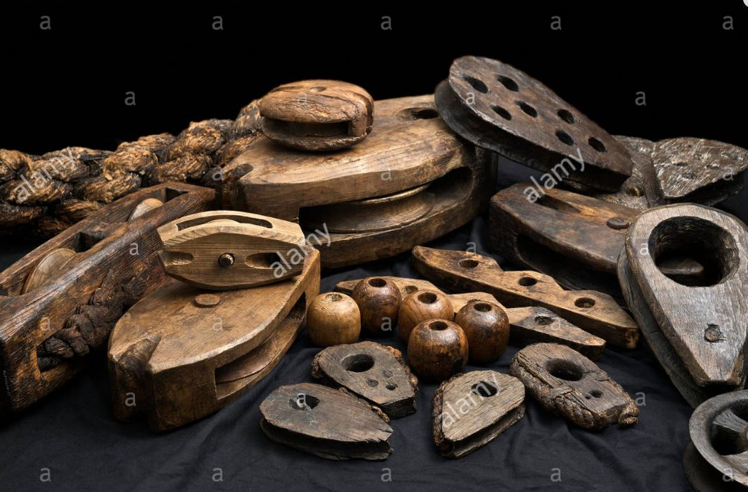
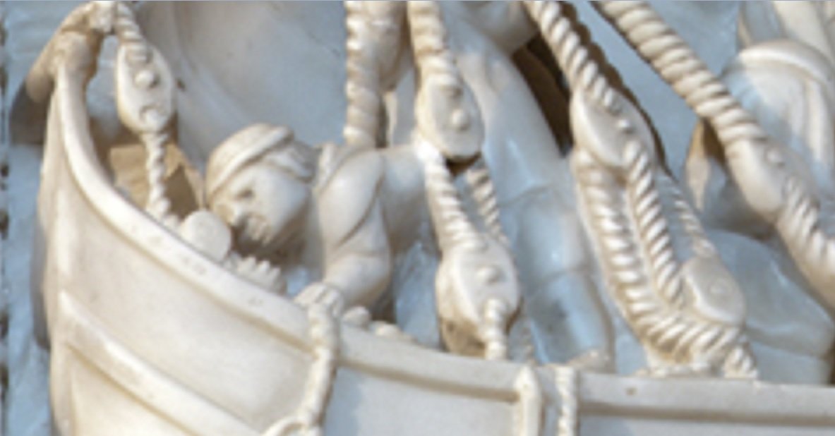
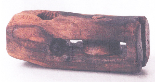
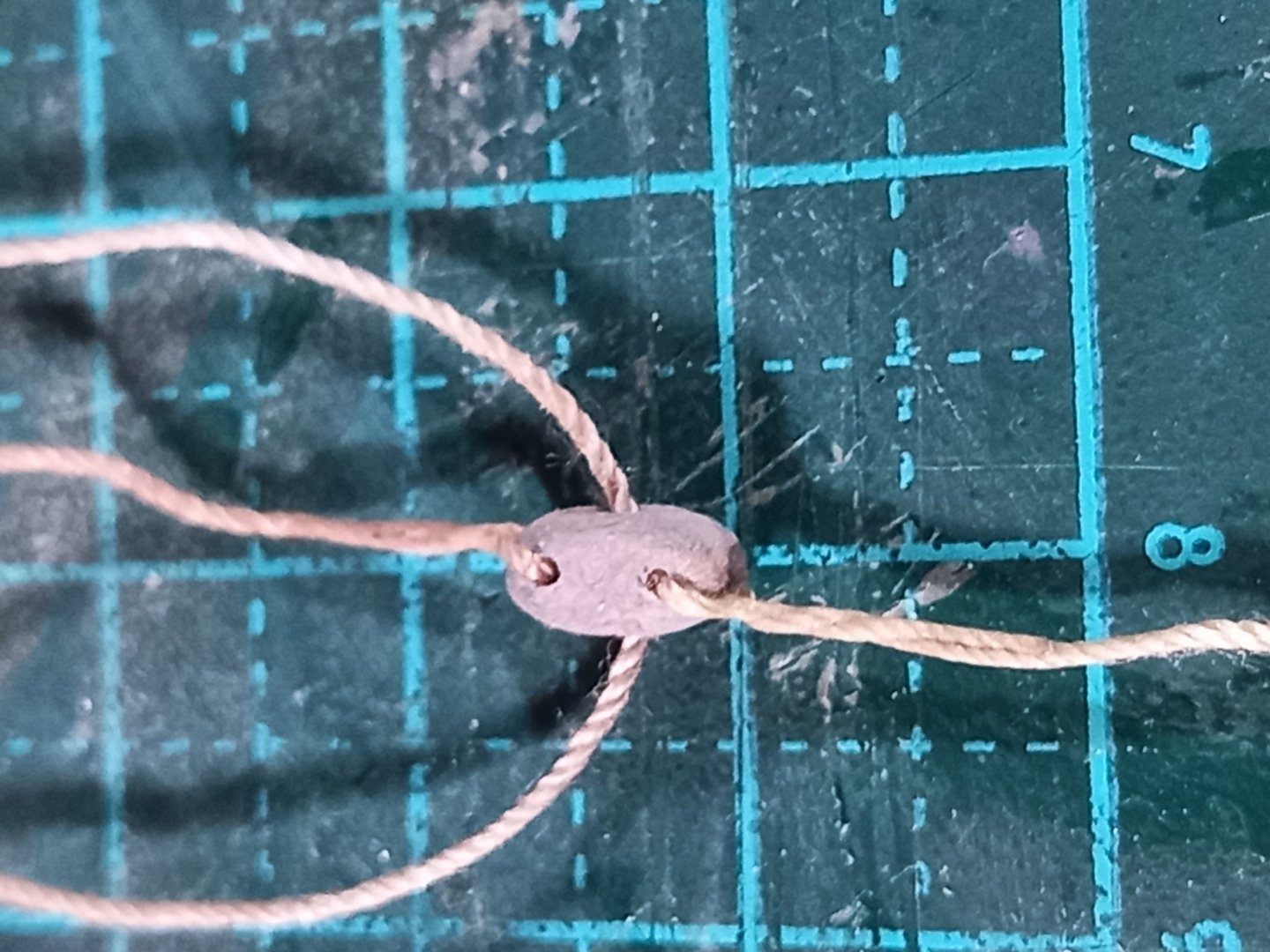
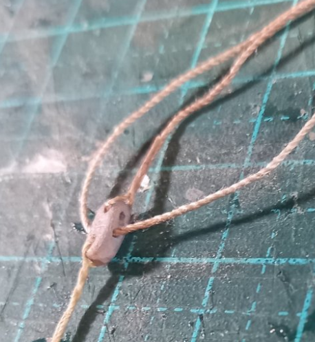
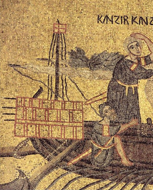
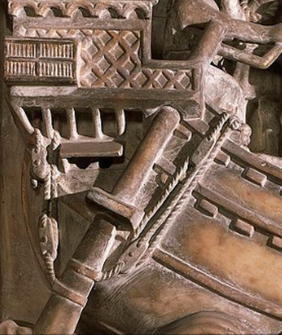
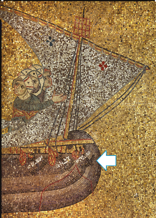
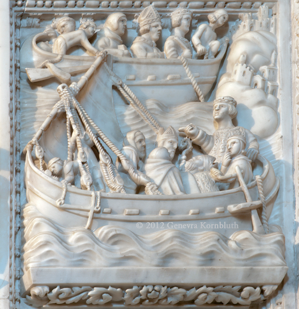
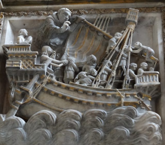
Well, you learn something new every day (if you're not careful!). Today, whilst working on the blocks to control the side rudders I discovered something I'd missed. The best depictions of mediaeval Mediterranean blocks I know of are in the carvings from from the church of San Pietro in Ciel d'Oro, Pavia of 1362 and the Arch of St Peter the Martyr, Church of Sant'Eustorgio, Milan of 1336-38 as shown in post #463 above. Only 200 years or so wrong for my model, but in this business you take what you can get. But look at the way the blocks are connected to the tackles they relate to. No strops! Instead, the ropes go through holes in the blocks themselves. Just like the blocks on my earlier dromon build, which I based upon actual archaeological finds from even earlier (5th and 11th century AD) Byzantine ships, except that the earlier ones were simple rectangular prisms ("blocks" if you will - so that's where the name came from!) From a 5th century AD wreck found in the silted-up Harbour of Theodosius of Constantinople (modern Istanbul) during the Yenikapi archaeological dig. The Spanish Cantigas de Santa Maria of 1252-80 appears to show blocks of the same type: Unfortunately the level of detail shown in the above two carvings is extremely rare in contemporary representations. I can see the reason this kind of block went out of use - that hole could just 'pull out' under the forces the block was subjected to. Better to use a strop. But when did the changeover occur? Fascinating. Looks like I'm going to have to scroll through my picture collection and see if I can gather more evidence on all this. In any event, I've realised all the blocks I've so far put on this model are probably incorrect. Not that I'm prepared to change them now - it'll just have to be another learning experience. But I've made a start on new ones for the rudders, in line with what I've discovered. Before I did all this I was all set to add the blocks to the rudders. I'd looked at the fixings for them shown on the Arch of St Peter the Martyr (above) and they made sense. I was going to make metal straps around the rudders - one for the forward-pulling tackle (which lowers the rudder) and one below it for the aft-pulling tackle which raises it. Then I had another look at the mosaics I've been working from, and which I think should be my first port of call for such things. In the rare depictions of the tackles in the mosaics they seem to be tied to the rudders. You can see one just below the aftercastle (the rudder is raised and is horizontal). The other one I'm ignoring, as it seems to be connected to the bow of a small boat, not to the rudder, in what I hope is simply an artist error. This is backed up by another near-contemporary illustration, of St Ursula by Paolo Veneziano (active by 1333, died after 1358) showing the tackle fixed to the rudder with rope lashings. I began by temporarily gluing one of the rudders resting on its supporting through-beam so that the tiller was in the helmsman's hands (well, as well as I could manage it). I drilled a small hole through both through-beam and rudder shaft and put a brass pin through the two of them so they'd stay aligned together. Once I had the alignment worked out I took the rudder off again and put the two lashings on it, with a little loop at the business end of each one for the rope connecting it to the block. Note the first photo below shows it at that stage - I'm not very chronologically consistent with my photo-taking. The pin would be replaced in due course with a wooden peg that would be trimmed off and painted to be invisible when it was all finished. Then I bethought myself and came to the conclusion that a single rope should be lashed around the rudder and connect the block to it. So I removed it, preparatory to doing it that way instead (no photo I'm afraid). And I've fully attached the starboard anchor and added weathering - rust where the flukes of the anchor rest against the ship and some salt residue and green marine growth where the cable is held. The rust didn't show up enough on the first try, so since I took these photos I've added to it. And some more marine growth along with the salt residue where the water is pumped out amidships. I think I need to revisit the green - it's not very convincing yet. Steven

- 508 replies
-
- 19
-
-
-
Thanks everybody for the likes. Thanks particularly to Thukydides (and yes,I know who the original Thukydides was -a very appropriate name!) and to Glen. By the way, once I have those anchors properly located and catted, I intend to put rust streaks down the hull as well. Banyan, I must have been in the middle of my post when you sent yours, so I didn't see it. I'd agree abut 'common' belaying points, and in fact I've been forced to do this on the model whether I wanted to or not. But I wasn't thinking about the idea of having more than one rope that work together to be grabbed at the same time. Maybe for next time. Steven
-
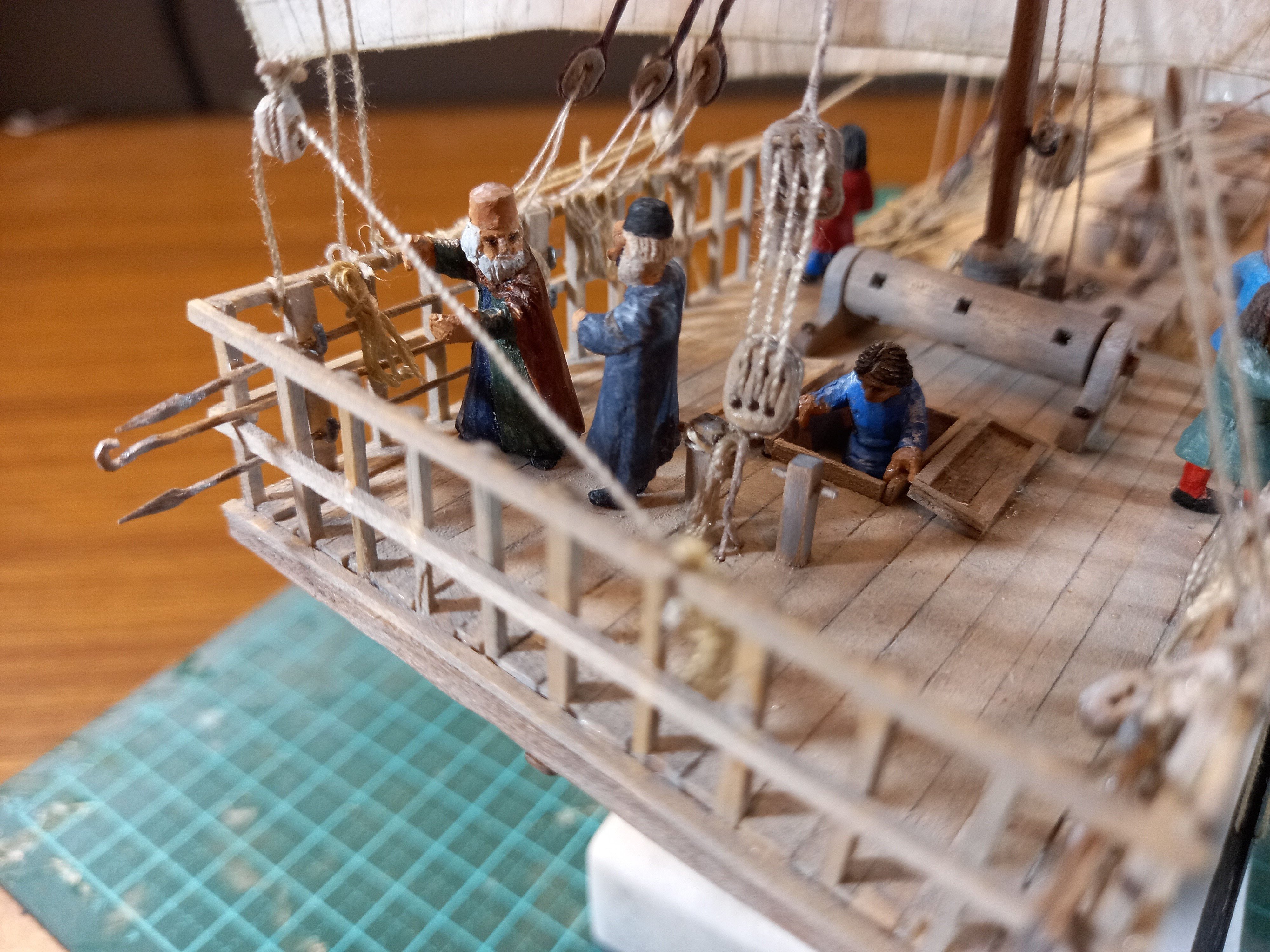
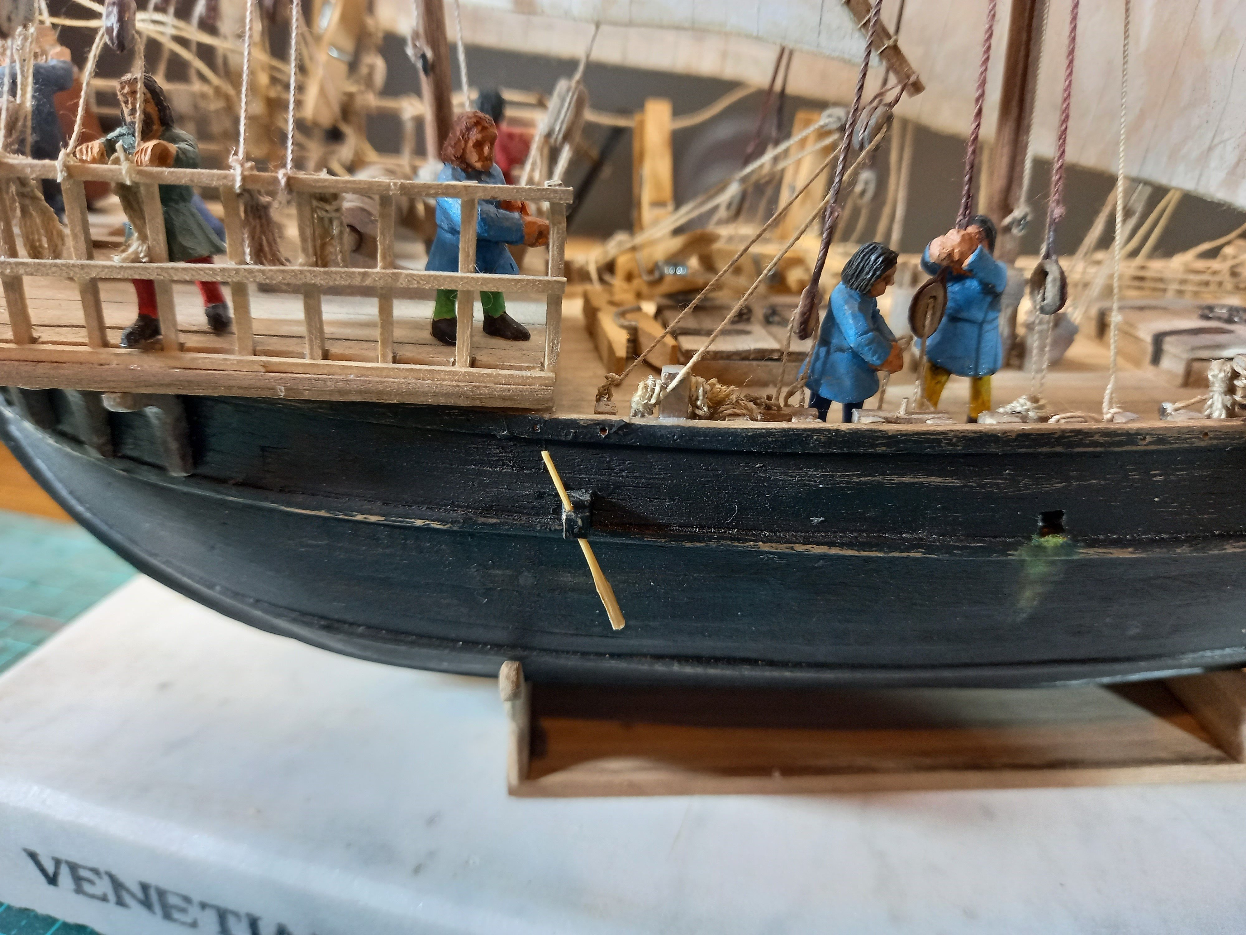
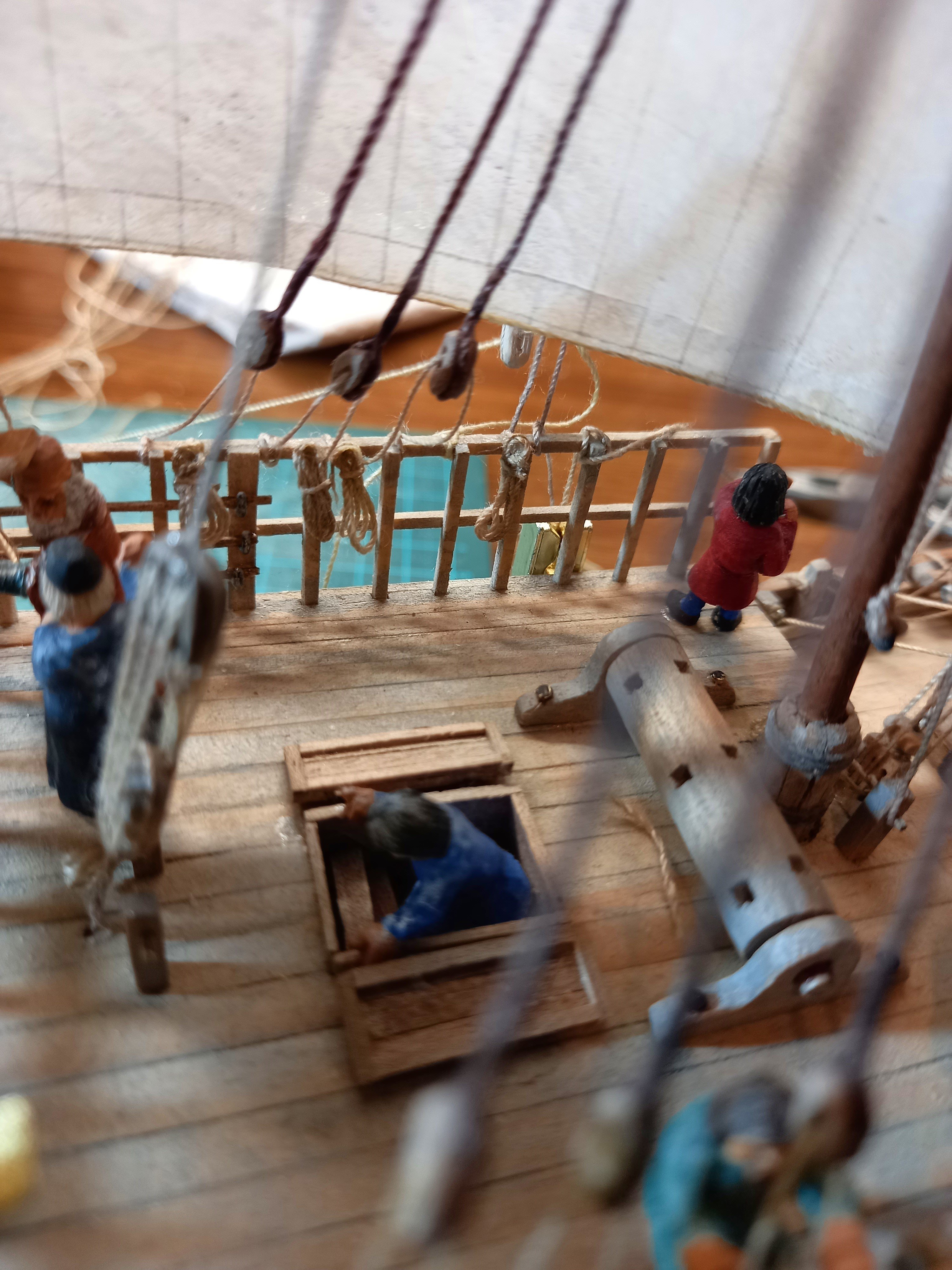
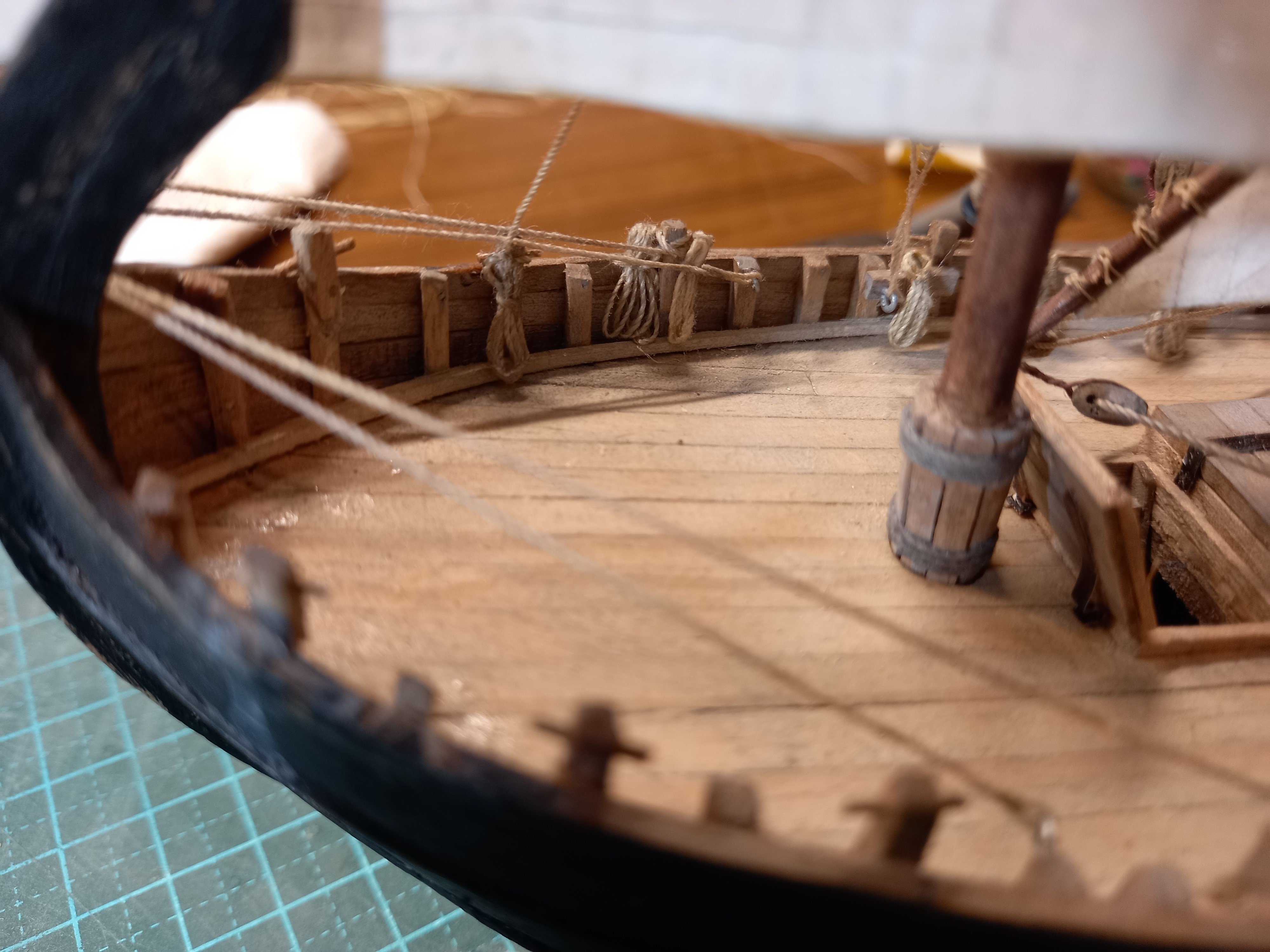
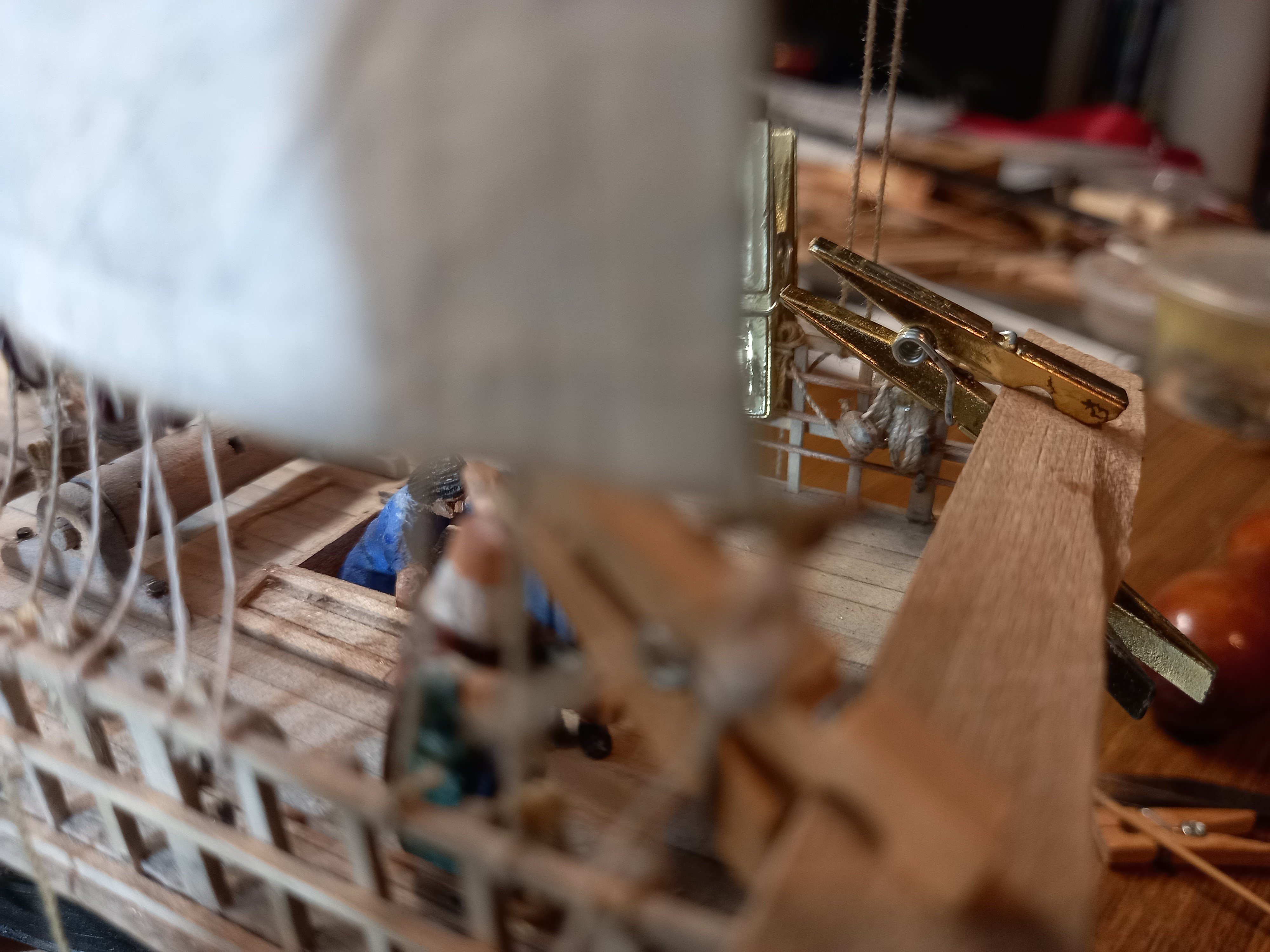
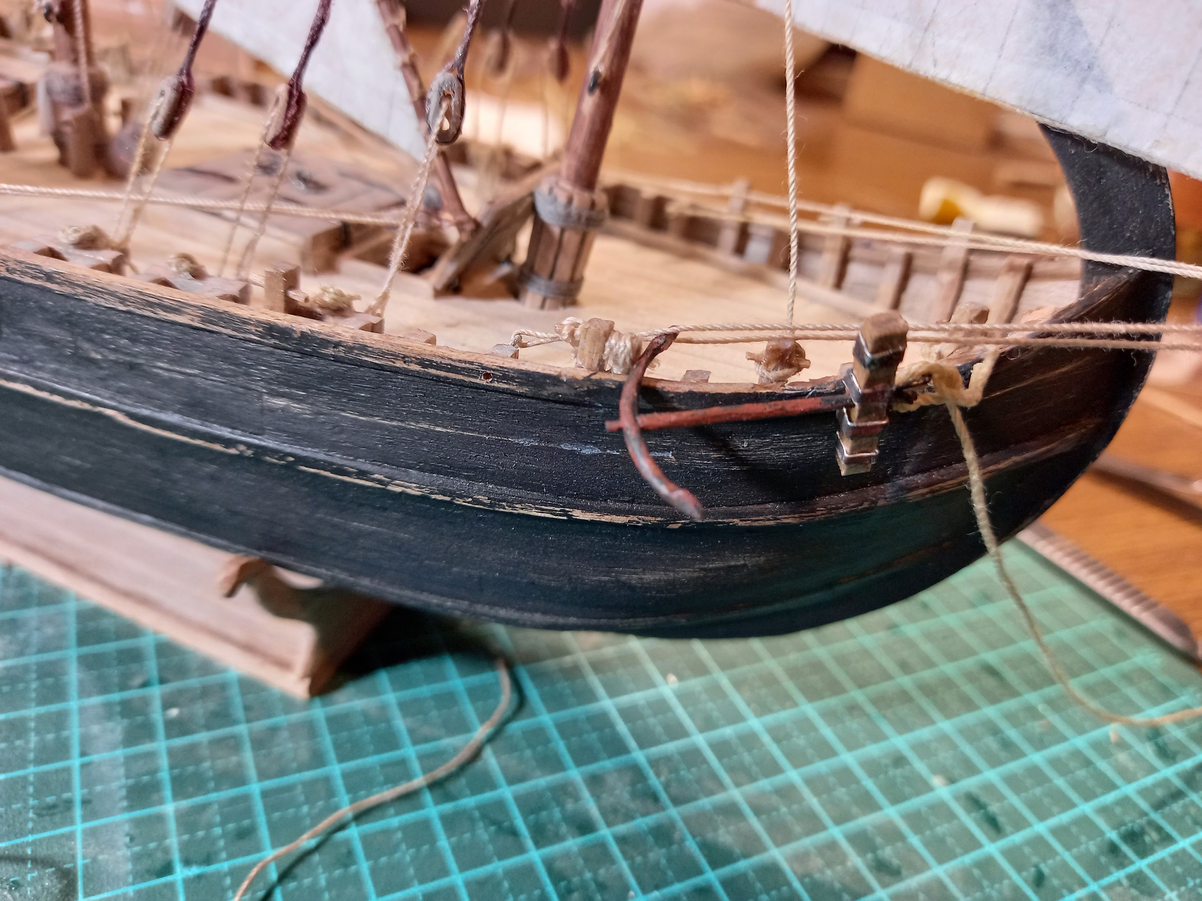
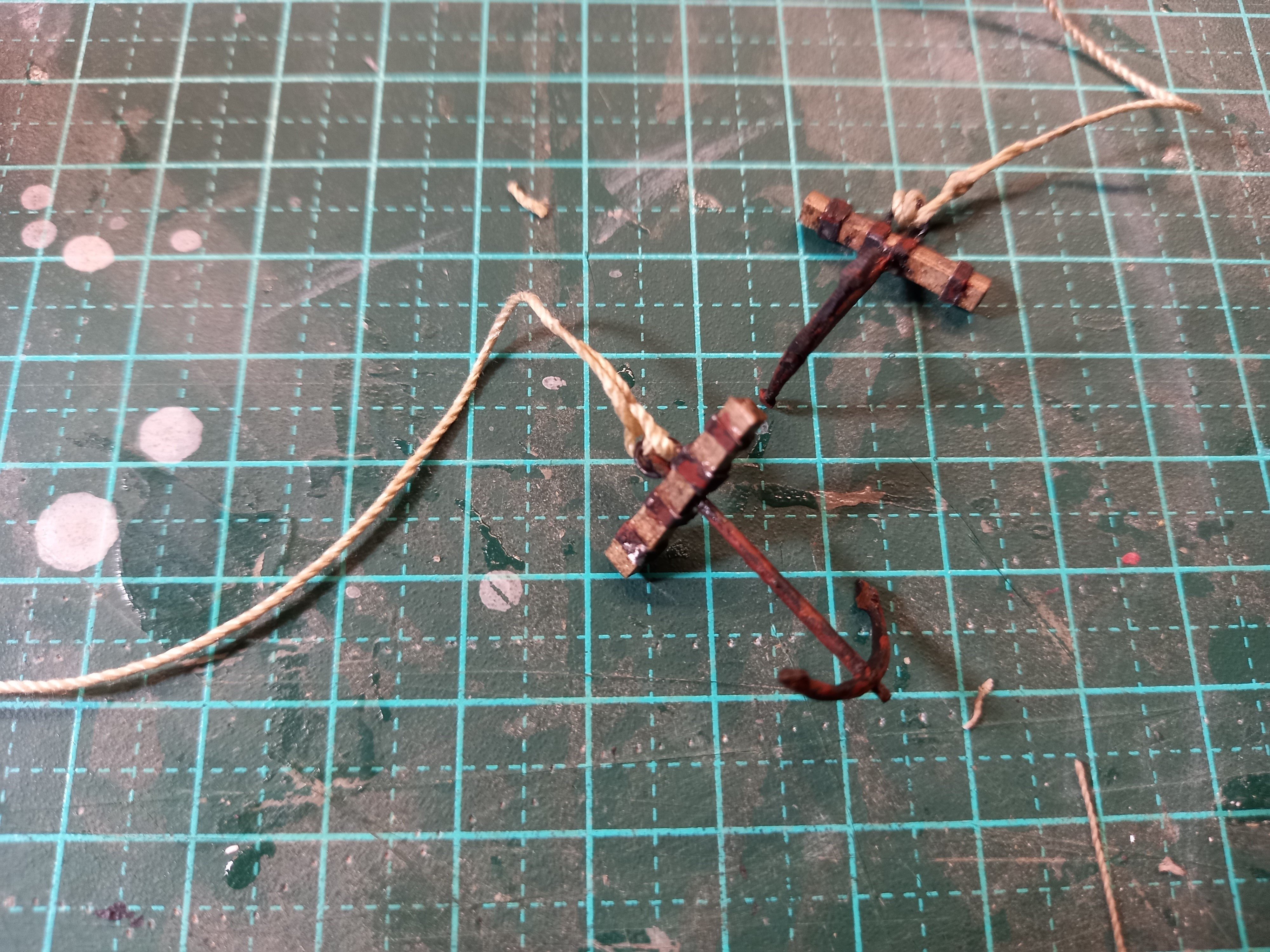
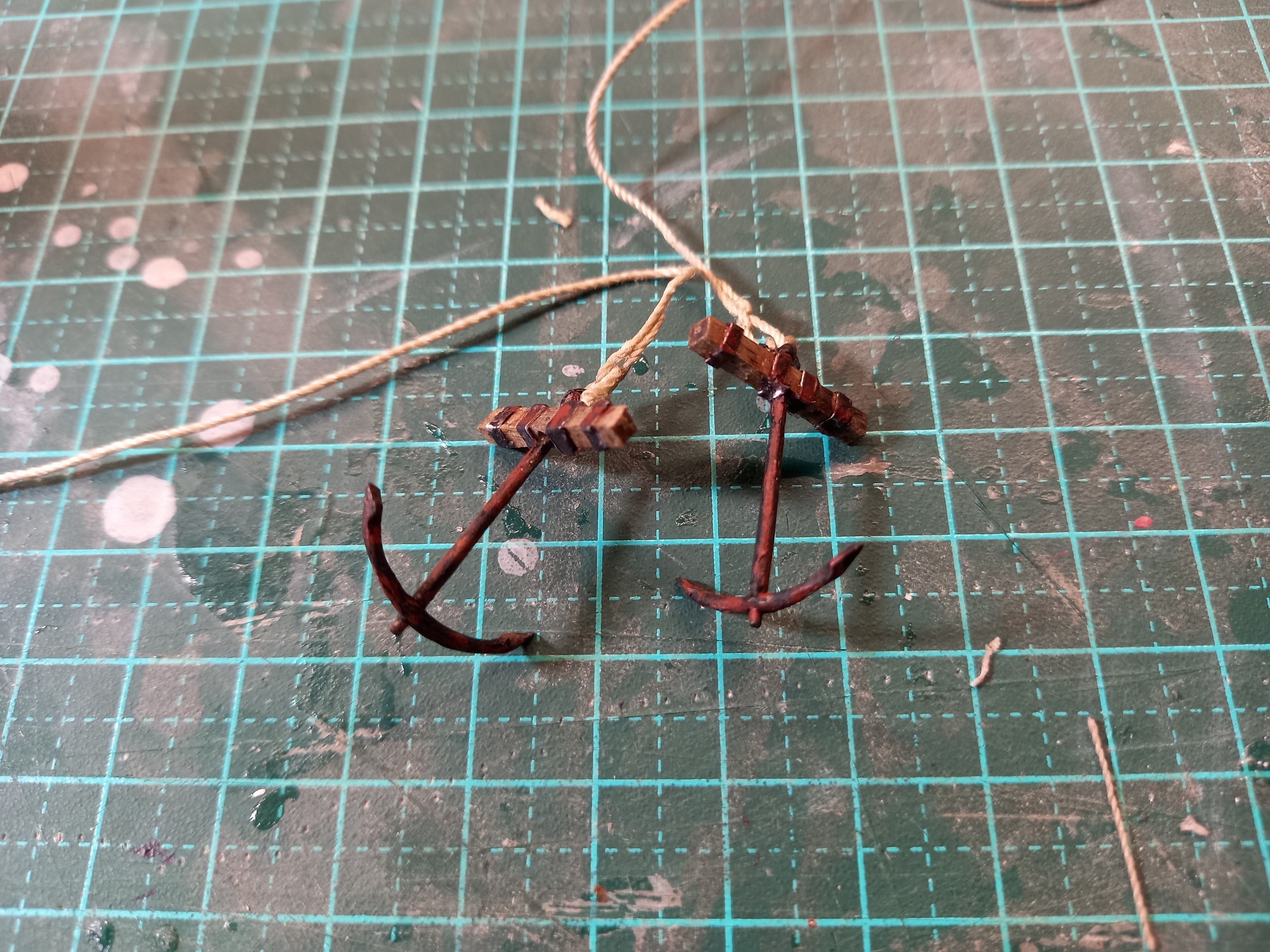
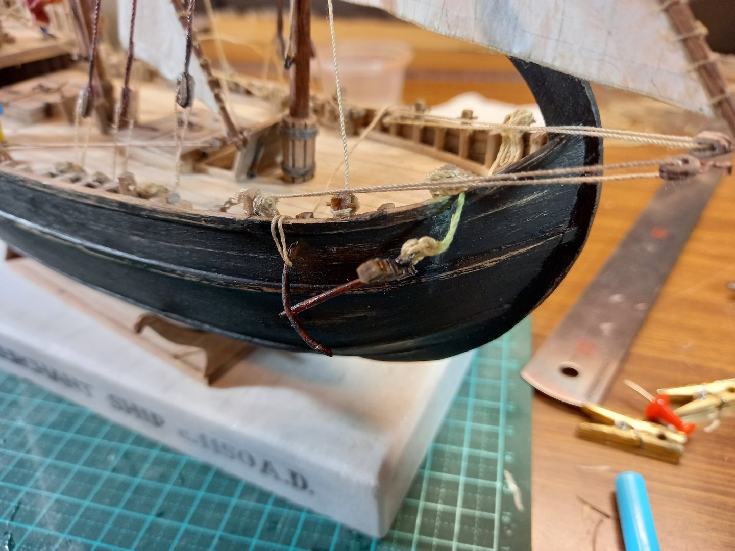
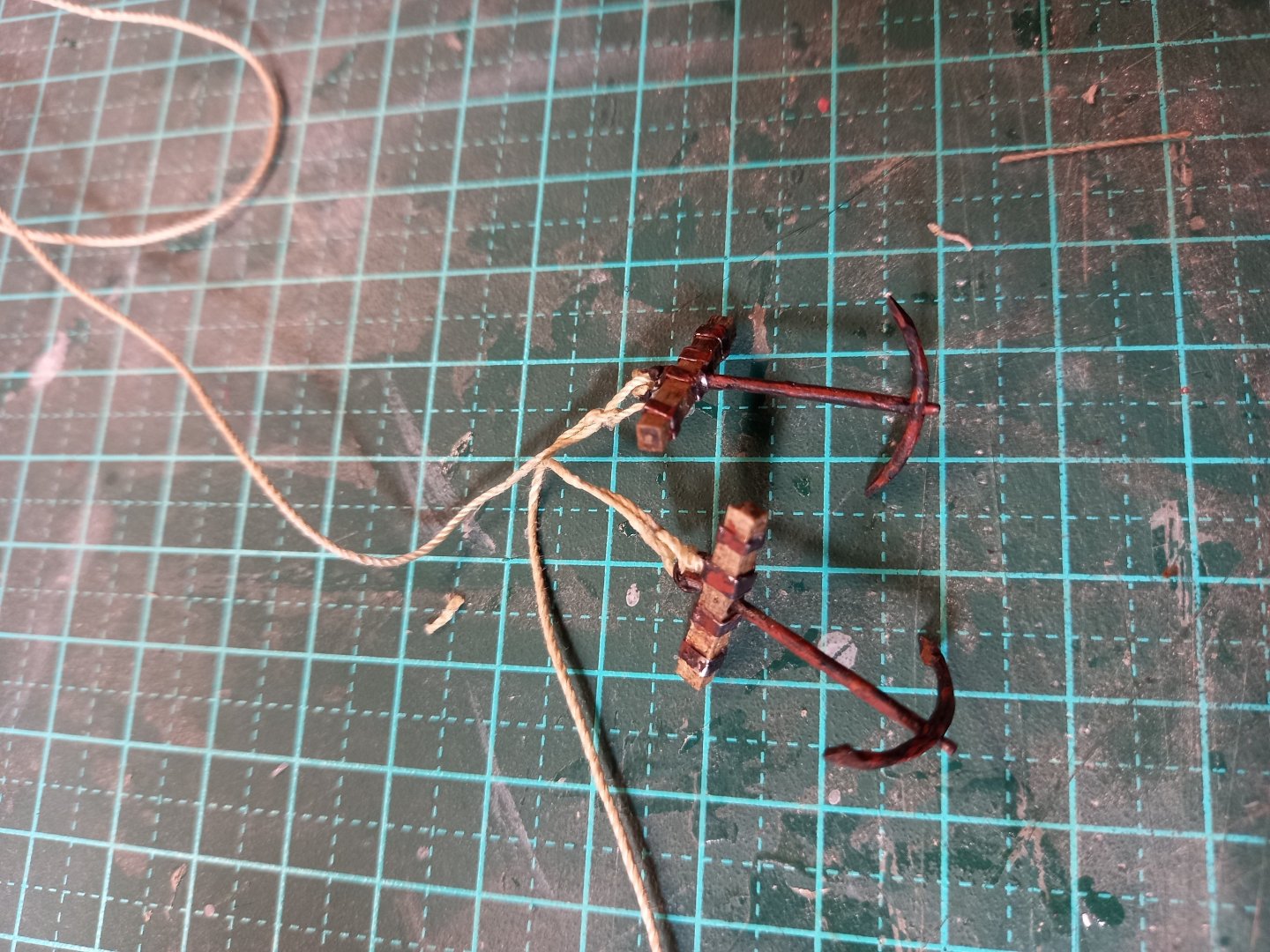
I've been working on rope coils. Until a moment ago I thought I'd made and put in place all I needed, but I've just become aware there are still a few more to do. So many coils, and I realise (again) that I didn't provide enough belaying points. But I've got so far now that I can't go back and fix that. It just has to be a learning experience for next time. By the way, note the nice catenary curves on the tackle for the slackened-off leeward shrouds. My coil-making has improved as I've gone along. The first ones were okay, but not brilliant. The latest ones are pretty good, if I do say so myself. Problem is, unless you're looking for them, they're not terribly obvious. I could have saved myself all that hassle and the model would have hardly looked different. But I would have known . . . And I solved (sort of) the issue of the sheet blocks on the weather side. I've tied one end of each sheet to a belaying point (I said there weren't enough!) with a coil on the free end, and the block (with a loop at the top to take a toggle) between the two. (You can see one of these blocks just below the gold clothespeg.) And I've completed and weathered the anchors: neglected and rusty, as befits a not terribly-well maintained merchant vessel. I had a bit of a research problem with these anchors - the only contemporary picture showing anchors at all is also from Saint Mark's, and shows three anchors at the bow - which could be quite believable - the technology for big heavy anchors hadn't yet been developed, so I can believe they made do with several smaller ones. BUT they're shown hanging off the gunwales by the cables, not catted. I find this difficult to accept. Interestingly, the cables appear to be looped around something at the gunwale and hanging outside the hull. Hmmm . . . The nearest other representations of anchors in time are about 200 years later, and who knows what developments in maritime technology took place in the interim. However, I find the suspension method much more believable, and that's the configuration I'll be following (though I have based the anchors on the ones in the mosaic). 1362 from the church of San Pietro in Ciel d'Oro, Pavia, Italy. 1336-38 Arch of St Peter the Martyr, Church of Sant'Eustorgio, Milan, Italy. And here is one of the anchors temporarily in place. Steven


- 508 replies
-
- 17
-
-
Hi and welcome to MSW. First, don't worry about mistakes. We all make them - the experienced builders just make more interesting ones! And wood is a very forgiving medium. Second, if you haven't already started one, begin a build log. First we get to see your model under way, second you can get help and advice and ask questions about any problems you might encounter. Best wishes, Steven [Edit] I just noticed your original post was almost a year ago - I must have missed it. But on searching MSW I don't see a build log, so I think my advice above still applies. Start one - it's a good group we have here, and very helpful. Steven