Louie da fly
-
Posts
7,993 -
Joined
-
Last visited
Content Type
Profiles
Forums
Gallery
Events
Everything posted by Louie da fly
-
 Beautiful work, and a beautiful vessel, Patrick. As usual your handiwork is superb. She's taking shape beautifully, and looks just like I'd imagined she would have in real life. Steven
 -
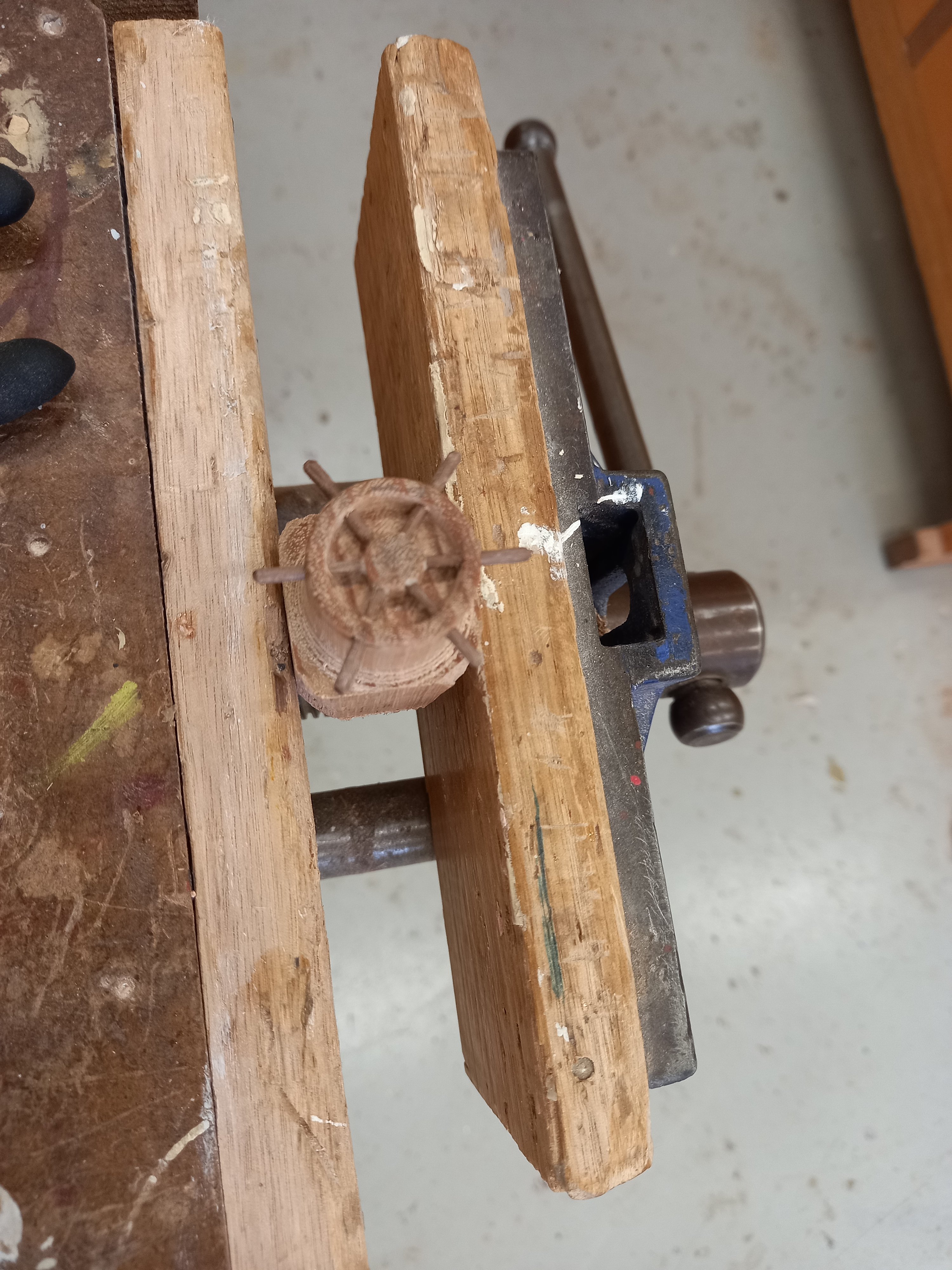
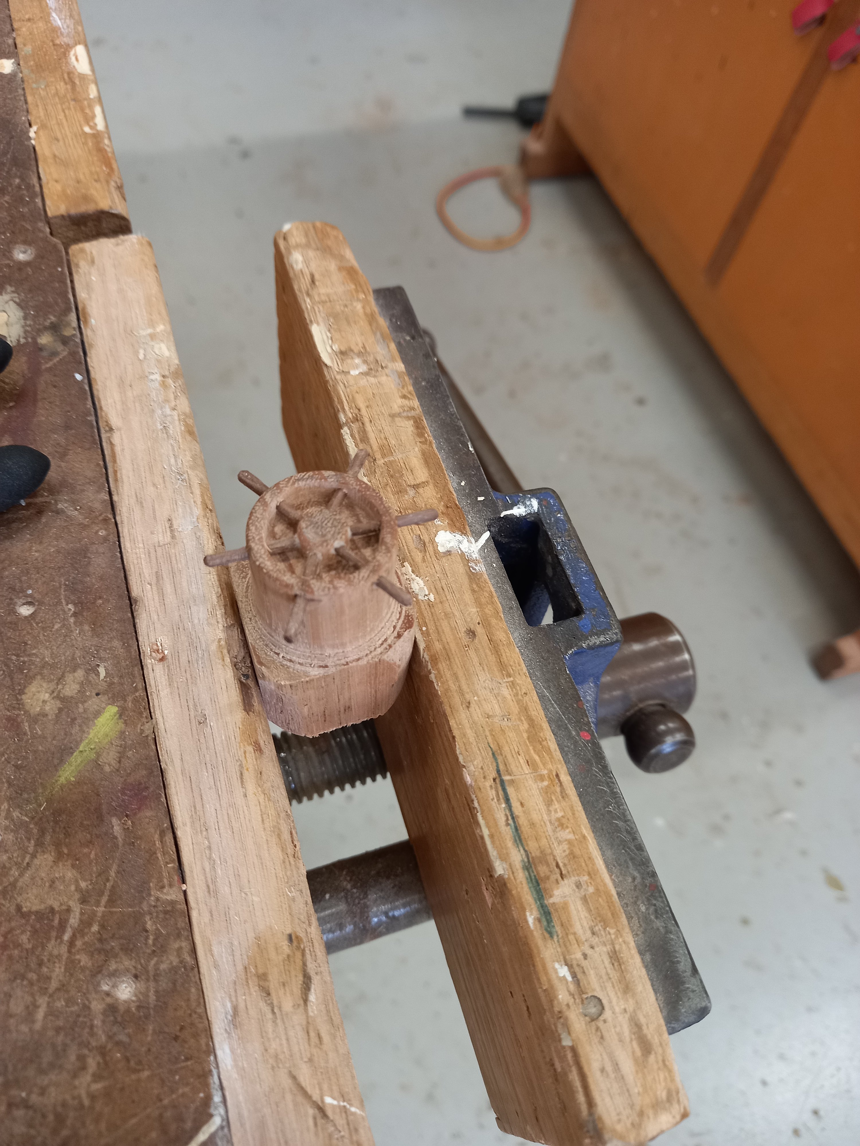
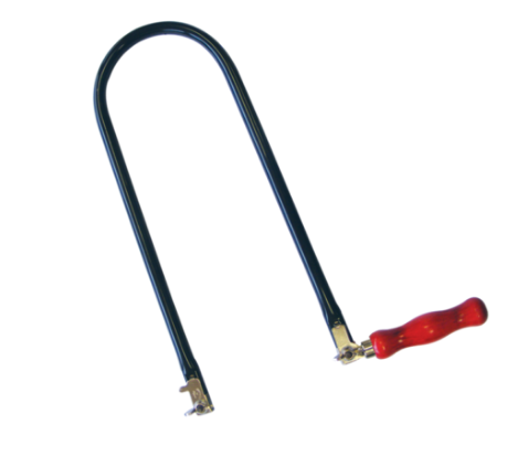
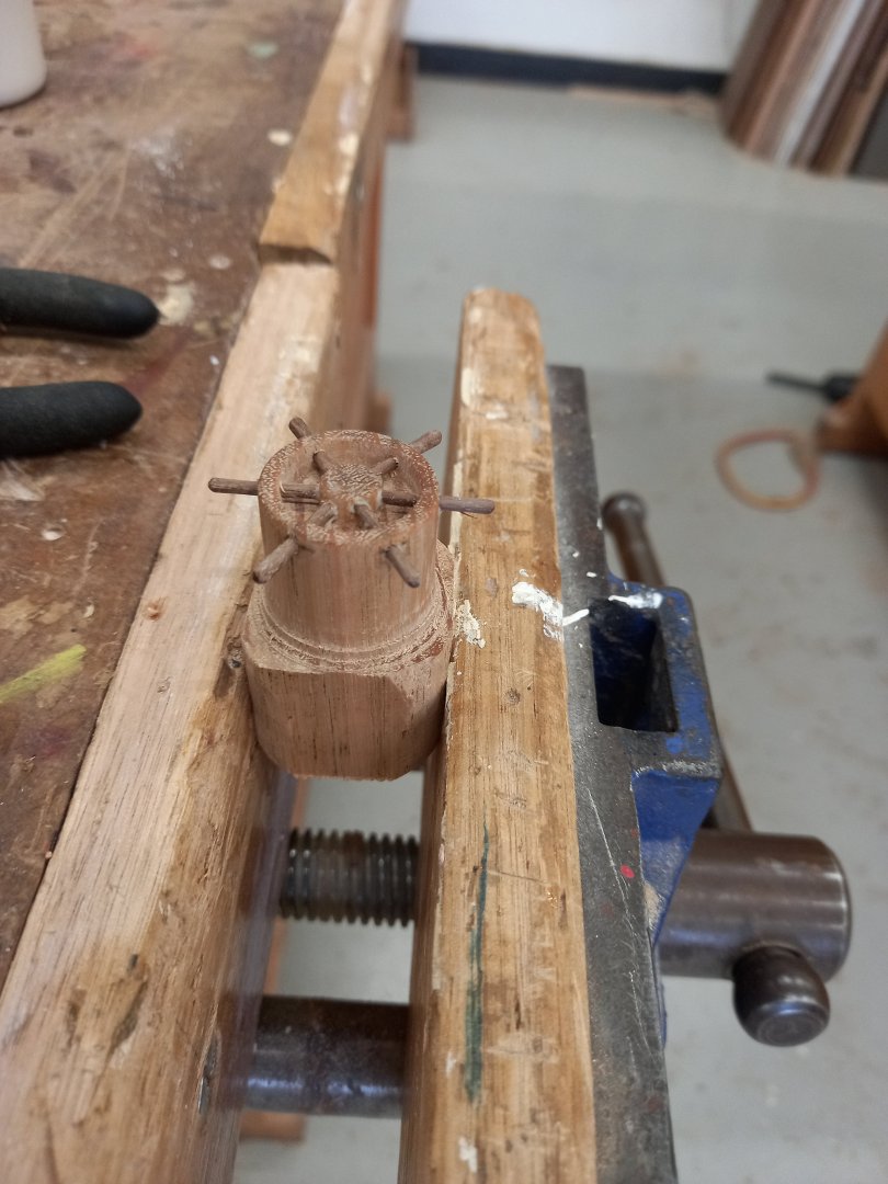
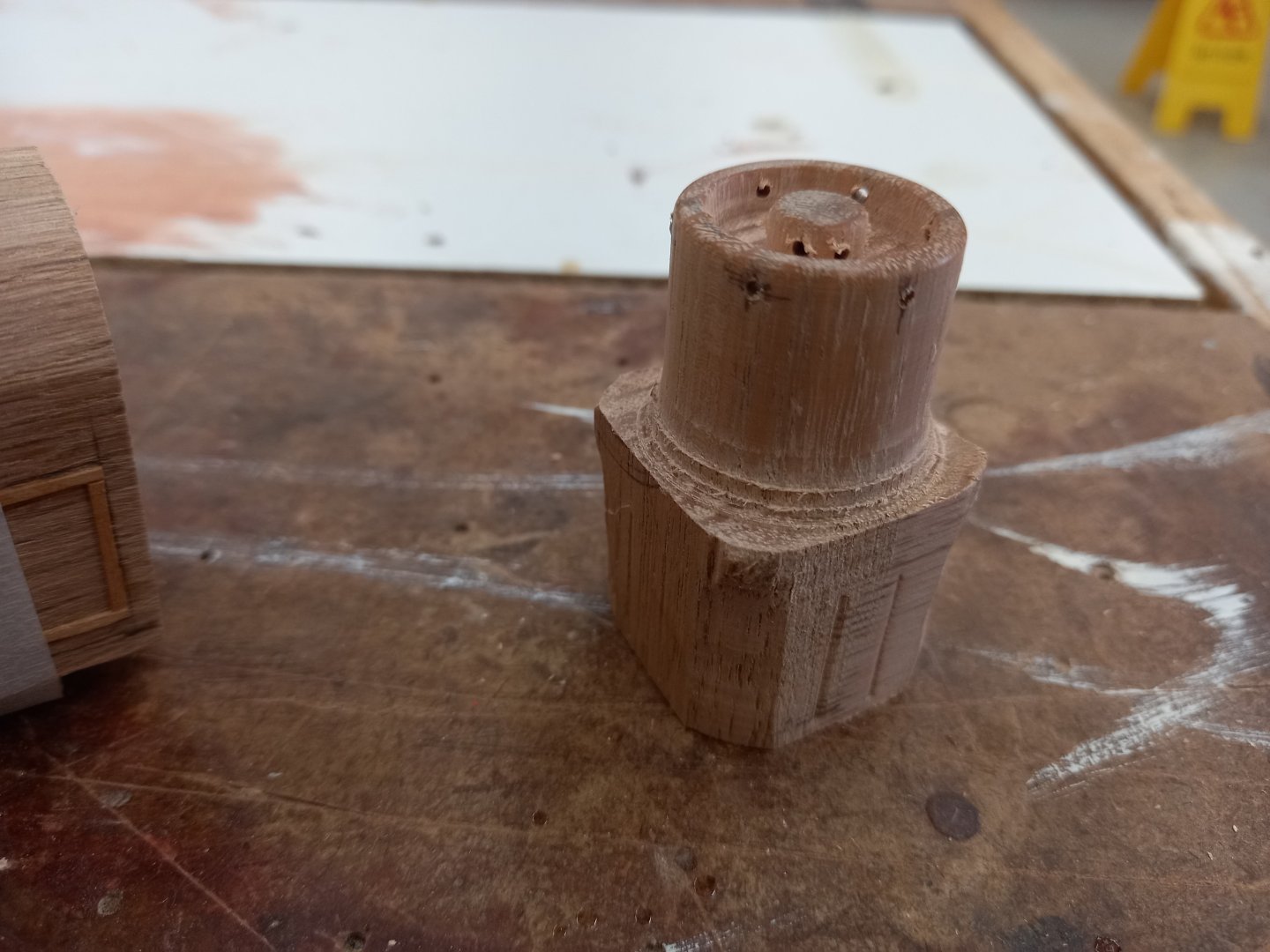
Oh, I don't know. If Woolies was gone, Coles would effectively have a monopoly. But I'm sure they wouldn't take advantage if that to hike the prices up . . . (irony). Back to the subject at hand. A-a-a-and - IT WORKED! In the event, I used a coping saw to cut it off instead of a fretsaw. It seemed like a better tool for the job. Very much heart in mouth, with the lathe at the slowest speed and gently pressing with the saw as the work rotated. But - voila! Success! (very pleased - I'd been very worried that sawing the wheel off the base would destroy it, but it's turned out just as I'd hoped.) Steven
- 110 replies
-
- 14
-

-
- Paddlewheeler
- Ballarat
- (and 3 more)
-
Pat, I may end up using a wider bladed saw. Depends what's available. But I also need very fine teeth if I don't want to destroy the thing. I'm using toothpicks for the posts that support the awning - at least for the smaller model - and they work well. For the larger one, bamboo skewers or something similar. Andrew, the NAAFI is of course famous from the Highly Esteemed Goon Show. But with the motorised paddles and pool I really think you're asking a bit more than I had in mind . . . Steven
- 110 replies
-
- 5
-
-
- Paddlewheeler
- Ballarat
- (and 3 more)
-
Hello from South West of England.
Louie da fly replied to Missile-Monkey's topic in New member Introductions
Coincidence - I was just watching a thing on TV of Martin Clunes (who lives in Dorset) and a self-described "lady novelist" doing the rounds of the county seeing places mentioned in various books (especially Thomas Hardy's novels). Beautiful place, Dorset. I missed out when I was in the UK - we went to Hampshire and Somerset but never got to Dorset. Looks like we need to go back sometime. A paddlesteamer sounds really interesting. Have fun with it, and make sure you start a build log so we can see your progress. The people on MSW are very friendly and helpful, so don't hesitate to ask questions if you hit problems. And photos! Post lots of photos! Steven -
Keith, I intend to mount it back into the lathe and slice it off (carefully) with a traditional fretsaw (very fine blade) as the lathe turns. Steven
- 110 replies
-
- 4
-
-
- Paddlewheeler
- Ballarat
- (and 3 more)
-
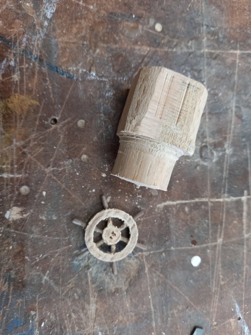
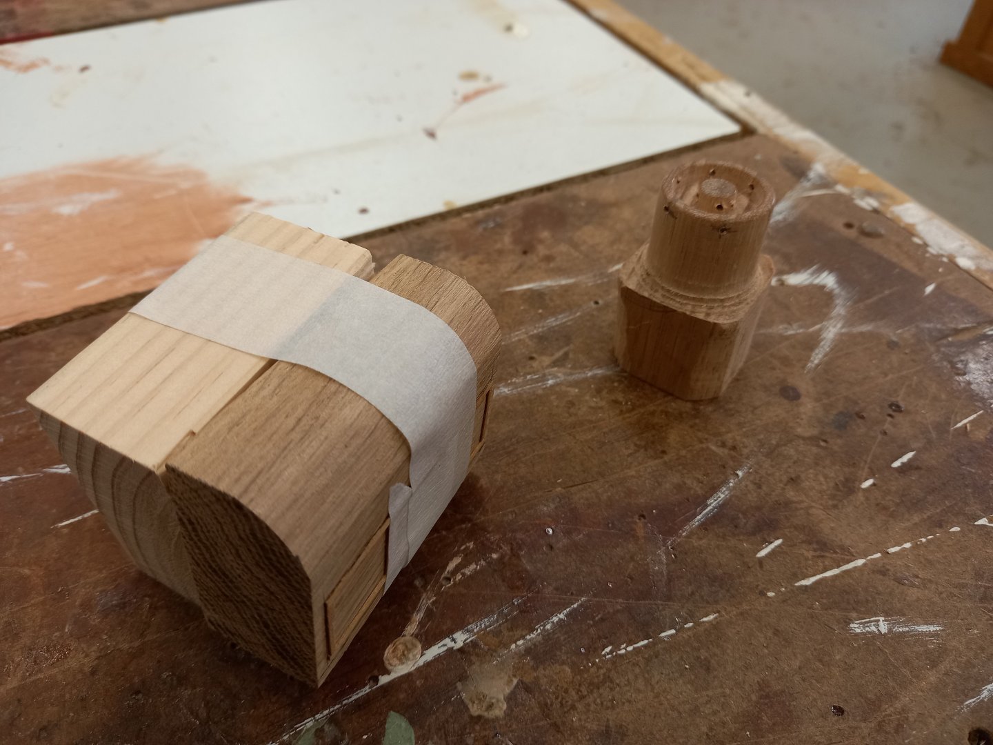
And here's the ship's wheel; just waiting for the glue to dry and I can cut it off its base. Should happen on Monday. Wish me luck! Steven


- 110 replies
-
- 13
-
-

-
- Paddlewheeler
- Ballarat
- (and 3 more)
-
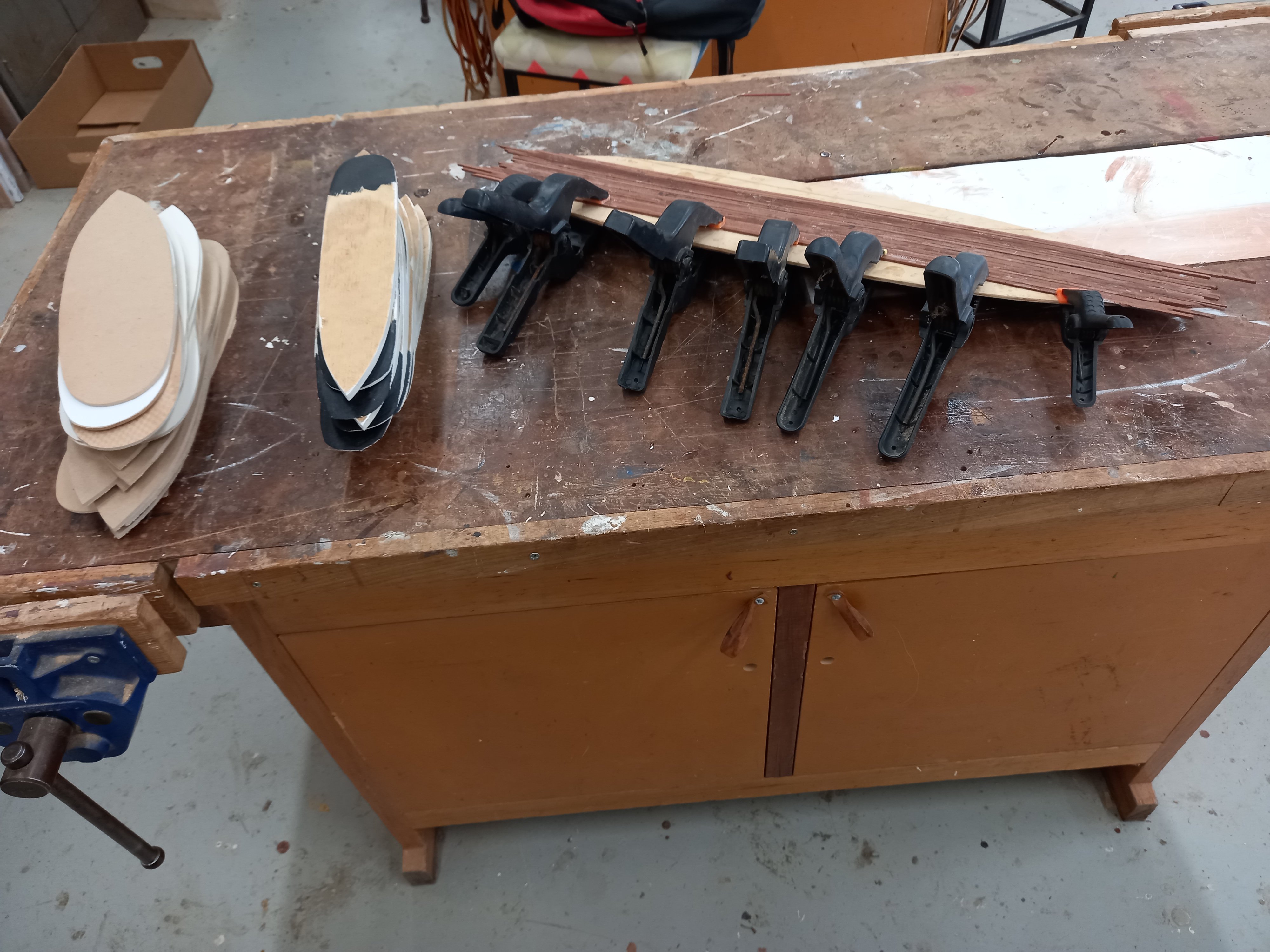
Here are 13 hulls, awnings and 'verandahs' (promenade decks?). And the thing with all the clamps on it is the promenade deck for the big model - I'm gradually adding planks; one or two each day. Plus the deck fittings for the wheel and what I think is storage. And the wheel itself under construction. I cheated with this. I asked a fellow Men's Shedder to turn it on the lathe because I don't have the skills. You can see the little holes in the sides for the handles. Once they're in place I'll slice it off its substructure and we should have a wheel instead of a cylinder. Steven

- 110 replies
-
- 11
-
-
- Paddlewheeler
- Ballarat
- (and 3 more)
-
Glen, 'chuffed' means pleased. You can be mildly chuffed or extremely chuffed. I think they were near the top end of the scale. One asked me if it would be possible to get his yacht model repaired, others were very interested in the idea of selling the models to the public - lots of people come here from Melbourne and have a nice trip in the lake in the paddlewheeler. What nicer than to then buy a model of the boat? Roger, I agree about the cost factor. The wood is donated - we have far more than we know what to do with, and the machinery to cut it to size. I'm hoping I can figure out a jig to make mass production easier. Oh, and 13 is just the start! Steven
- 110 replies
-
- 7
-
-
- Paddlewheeler
- Ballarat
- (and 3 more)
-
Thanks for the likes and comments everybody. I got into preparing multiple 1:50 hulls today - I think I have about 13 made so far. But I only have half a dozen "verandahs" and awnings so far, so I've got some catching up to do. Also working on the sort of roll-top desk thingy (see photo No. 3 in post #18 above) for the big model - it supports the wheel on the full-sized vessel, but I'm only doing the wheel for the big one. I have a cunning plan for how to make it. It remains to be seen whether it will work. Pat, 3D printing would certainly save time and effort, but as I have absolutely no experience or equipment I expect I'll just build up the seats and gates with strips of wood (and they're free!) Steven
- 110 replies
-
- 4
-
-
- Paddlewheeler
- Ballarat
- (and 3 more)
-
I was invited to take the almost-complete 1:50 model along to the meeting of the Golden City Paddle Steamer Museum Society (the group of volunteers who own and run the Golden City) so they could have a look at it. They were all very chuffed with it, thought it was brilliant, loved the idea of selling 1:50 models to visitors as a fundraiser. And wanted to know if the big (1:25) model would be ready to display in time for the "season" (they only run the full-sized one on the lake from October to April due to Australia being upside down and having winter in June.) I wasn't able to give a definite undertaking because of uncertainties in what problems might arise in building the big one, but just between you and me I think it's quite possible. They even have a big glass display case (museum-sized) which they recently acquired and in which they plan to display it. All rather positive. Now I actually have to deliver the goods! Steven
- 110 replies
-
- 9
-
-
-
- Paddlewheeler
- Ballarat
- (and 3 more)
-
That's looking very good. Quite convincing - I look forward to seeing the barrel once this process is complete Steven
-
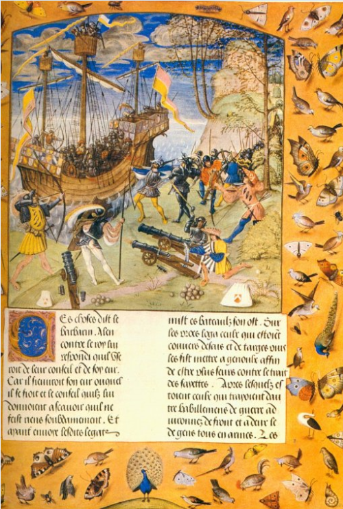
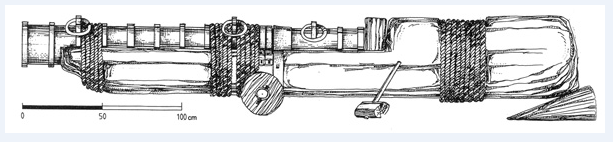
I've put quite a bit of study into guns of this period, and you're certainly on the right track. You might be interested in this gun from the Genoese ship La Lomellina which sank in 1516 (which I believe was probably built in 1503). And this picture which I believe shows the Lomellina's predecessor, which sank in 1503, as it is flying the flag of the Lomellini family, and which has some interesting cannons. Steven
- 23 replies
-
- 10
-
-

-
I believe this must be the original inspiration for C.S. Forester's book The African Queen, on which the movie is based, except that the director, John Huston, changed the ending. In the book the African Queen doesn't sink the Königin Louise - instead she is lost on the storm and Rose and Charlie's quest fails. Then two fast motor launches with quick-firing guns, transported overland to the lake, out-manoeuvre and sink the German ship. To be honest, I prefer the movie ending. As well as the superb work by Bogie and Kate, who did a beautiful job of portraying two ordinary people (Rose has become resigned to her role as the support for her mediocre brother, and Charlie is a silly weak little man) who fall in love and together achieve something magnificent. Steven
-
It's good to see this project back again after a long break. I'm looking forward to seeing further progress. Steven
-
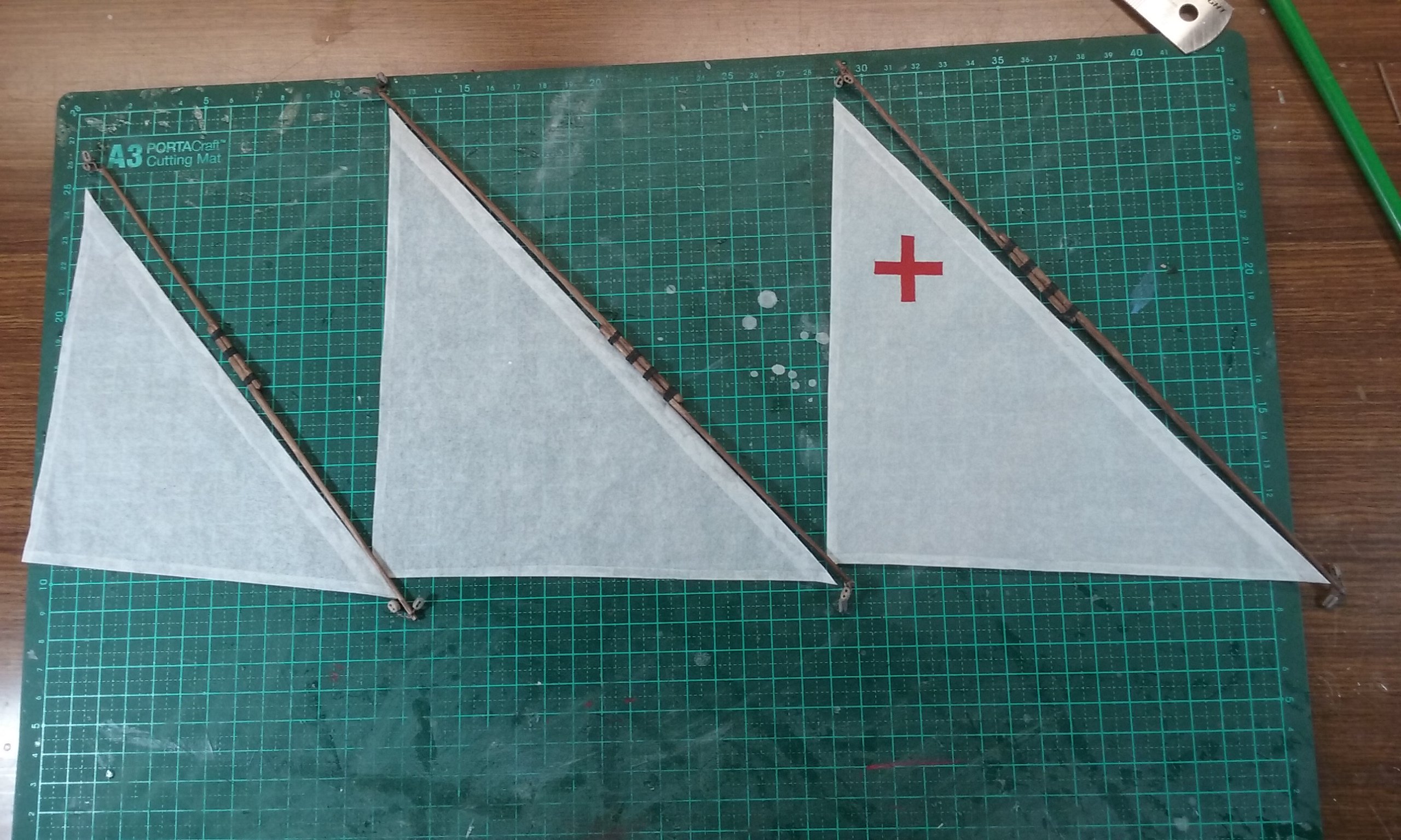
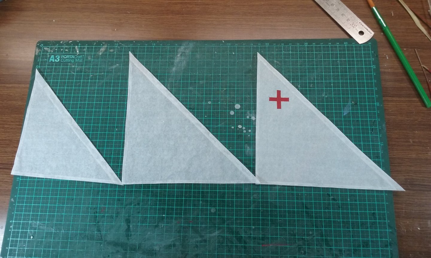
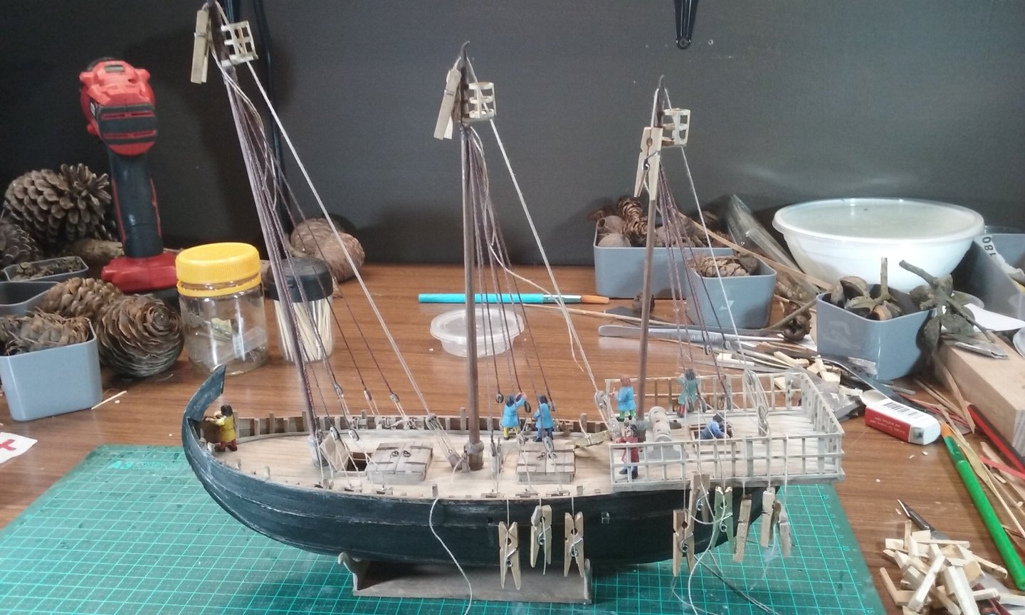
Thanks Roger. That's my opinion entirely. A lot of this is educated guesswork based on (extremely!) inadequate source material. Of course we can't be sure it's all correct, but a lot of the fun is in the investigation of source material and speculation as to how it could be done, given the pictorial evidence (often affected by artistic licence), the archaeological evidence (often frustratingly incomplete) and the practicalities of sailing a wooden vessel. And if later evidence proves one of the guesses wrong, one still has the satisfaction of having done the best one could with the information that was available at the time. So, on to current progress. Shrouds and halyards in place, but only the foremast shrouds have been finalised. I really do need to clear my workdesk before I take photos! I made new silkspan sails - I wasn't happy with the first iteration. This time I made them oversize and folded the edges over instead of gluing strips of silkspan to the edges. The cross was painted on with Tamiya acrylic paint. I needed two coats for the "face" side and one for the other side. Considerably happier with the second version. And I've added the blocks to the yards - for the tacks at the lower ends and the vangs at the upper. Druxey, if I might pick your brains - how did you attach the bolt ropes to your silkspan sails (they look particularly good)? And the robands? Steven

- 508 replies
-
- 11
-
-
Very sorry to hear that, mate. I can only send you my best wishes. Steven
-
That's ok. Take your time and concentrate on getting well. And when you get the time, you'll probably find the diorama work is good therapy in your recovery. Steven
-
You've done a beautiful job. Congratulations on completing - a lot of work, but well worth it. Steven
-
Oops. I'd meant to reply to this earlier, ut it somehow got missed. Very glad to be of help in providing a possible 'backdrop' for your knarr. I'll be interested to see what kind of setting you do end up giving it. I've been thinking seriously about dioramas myself recently (ever since I saw the endless lines of near-identical tanks and aircraft at the Ballarat Modelling Exhibition - interesting for enthusiasts but boring for the general public). I think a setting adds immensely to a model. Looking forward to progress on this one. Steven
-
Looking forward to progress on this one. Do we get more of the back-story about the green drakkar? Steven
-
Thanks, Eric. I'm afraid I'm a bit of a show pony in that regard. I enjoy trying for a bit of extra interest in my builds to spark the attention of those in the know. Steven
-
Why thank you, Mark. Unfortunately, they are going to be on the weather side, so I think Doreltomin's point stands. However, perhaps a flick of the rudder(s) could take the load off for a short time even if they were weather shrouds. [And of course if they were just completing a tack and hadn't yet got under way, these guys tightening the last weather shroud could well be believable]. Tartane, yes, I'm still going to be using lateen sails. I've looked carefully at your arguments and they aren't convincing enough to make me change. I realise that you have the best intentions in making your suggestions, but I have done plenty of research of my own and I'm satisfied that I'm making the right decisions. What may have been the practice for a chebec in the 18th/19th century is by no means necessarily what was done in the 12th century, and I believe I have ample evidence to back me up. Theoretical reconstructions will always be a matter of interpretation of the available evidence, and our interpretations are different. I think the best policy is for us to agree to disagree. I'm not really willing to engage in any further discussion on these points, as I find it's distracting me from the build. Steven
- 508 replies
-
- 11
-